EP2741161A2 - Autonomous apparatus for processing a surface and method for detecting the position of the autonomous apparatus - Google Patents
Autonomous apparatus for processing a surface and method for detecting the position of the autonomous apparatus Download PDFInfo
- Publication number
- EP2741161A2 EP2741161A2 EP13401133.7A EP13401133A EP2741161A2 EP 2741161 A2 EP2741161 A2 EP 2741161A2 EP 13401133 A EP13401133 A EP 13401133A EP 2741161 A2 EP2741161 A2 EP 2741161A2
- Authority
- EP
- European Patent Office
- Prior art keywords
- current
- image
- information
- orientation
- probabilities
- Prior art date
- Legal status (The legal status is an assumption and is not a legal conclusion. Google has not performed a legal analysis and makes no representation as to the accuracy of the status listed.)
- Granted
Links
- 238000000034 method Methods 0.000 title claims abstract description 70
- 238000012545 processing Methods 0.000 title description 2
- 239000002689 soil Substances 0.000 claims abstract description 34
- 238000009826 distribution Methods 0.000 claims abstract description 22
- 239000002245 particle Substances 0.000 claims description 57
- 230000007613 environmental effect Effects 0.000 claims description 26
- 238000003971 tillage Methods 0.000 claims description 16
- 239000013598 vector Substances 0.000 claims description 13
- 238000012937 correction Methods 0.000 claims description 12
- 238000011161 development Methods 0.000 claims description 7
- 230000018109 developmental process Effects 0.000 claims 2
- 230000003287 optical effect Effects 0.000 description 4
- 238000004140 cleaning Methods 0.000 description 3
- 238000011156 evaluation Methods 0.000 description 3
- 238000001454 recorded image Methods 0.000 description 3
- 230000000007 visual effect Effects 0.000 description 3
- 230000009897 systematic effect Effects 0.000 description 2
- 238000004891 communication Methods 0.000 description 1
- 230000001419 dependent effect Effects 0.000 description 1
- 238000001514 detection method Methods 0.000 description 1
- 238000003306 harvesting Methods 0.000 description 1
- 238000005259 measurement Methods 0.000 description 1
- 238000012986 modification Methods 0.000 description 1
- 230000004048 modification Effects 0.000 description 1
- 230000001953 sensory effect Effects 0.000 description 1
- 238000009331 sowing Methods 0.000 description 1
- 230000002123 temporal effect Effects 0.000 description 1
Images


Classifications
-
- G—PHYSICS
- G05—CONTROLLING; REGULATING
- G05D—SYSTEMS FOR CONTROLLING OR REGULATING NON-ELECTRIC VARIABLES
- G05D1/00—Control of position, course or altitude of land, water, air, or space vehicles, e.g. automatic pilot
- G05D1/02—Control of position or course in two dimensions
- G05D1/021—Control of position or course in two dimensions specially adapted to land vehicles
- G05D1/0231—Control of position or course in two dimensions specially adapted to land vehicles using optical position detecting means
- G05D1/0246—Control of position or course in two dimensions specially adapted to land vehicles using optical position detecting means using a video camera in combination with image processing means
-
- G—PHYSICS
- G01—MEASURING; TESTING
- G01C—MEASURING DISTANCES, LEVELS OR BEARINGS; SURVEYING; NAVIGATION; GYROSCOPIC INSTRUMENTS; PHOTOGRAMMETRY OR VIDEOGRAMMETRY
- G01C21/00—Navigation; Navigational instruments not provided for in groups G01C1/00 - G01C19/00
- G01C21/005—Navigation; Navigational instruments not provided for in groups G01C1/00 - G01C19/00 with correlation of navigation data from several sources, e.g. map or contour matching
-
- G—PHYSICS
- G05—CONTROLLING; REGULATING
- G05D—SYSTEMS FOR CONTROLLING OR REGULATING NON-ELECTRIC VARIABLES
- G05D1/00—Control of position, course or altitude of land, water, air, or space vehicles, e.g. automatic pilot
- G05D1/02—Control of position or course in two dimensions
- G05D1/021—Control of position or course in two dimensions specially adapted to land vehicles
- G05D1/0212—Control of position or course in two dimensions specially adapted to land vehicles with means for defining a desired trajectory
- G05D1/0219—Control of position or course in two dimensions specially adapted to land vehicles with means for defining a desired trajectory ensuring the processing of the whole working surface
-
- G—PHYSICS
- G05—CONTROLLING; REGULATING
- G05D—SYSTEMS FOR CONTROLLING OR REGULATING NON-ELECTRIC VARIABLES
- G05D1/00—Control of position, course or altitude of land, water, air, or space vehicles, e.g. automatic pilot
- G05D1/02—Control of position or course in two dimensions
- G05D1/021—Control of position or course in two dimensions specially adapted to land vehicles
- G05D1/0231—Control of position or course in two dimensions specially adapted to land vehicles using optical position detecting means
- G05D1/0246—Control of position or course in two dimensions specially adapted to land vehicles using optical position detecting means using a video camera in combination with image processing means
- G05D1/0253—Control of position or course in two dimensions specially adapted to land vehicles using optical position detecting means using a video camera in combination with image processing means extracting relative motion information from a plurality of images taken successively, e.g. visual odometry, optical flow
-
- G—PHYSICS
- G05—CONTROLLING; REGULATING
- G05D—SYSTEMS FOR CONTROLLING OR REGULATING NON-ELECTRIC VARIABLES
- G05D1/00—Control of position, course or altitude of land, water, air, or space vehicles, e.g. automatic pilot
- G05D1/02—Control of position or course in two dimensions
- G05D1/021—Control of position or course in two dimensions specially adapted to land vehicles
- G05D1/0268—Control of position or course in two dimensions specially adapted to land vehicles using internal positioning means
- G05D1/0274—Control of position or course in two dimensions specially adapted to land vehicles using internal positioning means using mapping information stored in a memory device
-
- G—PHYSICS
- G01—MEASURING; TESTING
- G01C—MEASURING DISTANCES, LEVELS OR BEARINGS; SURVEYING; NAVIGATION; GYROSCOPIC INSTRUMENTS; PHOTOGRAMMETRY OR VIDEOGRAMMETRY
- G01C22/00—Measuring distance traversed on the ground by vehicles, persons, animals or other moving solid bodies, e.g. using odometers, using pedometers
Definitions
- the invention relates to a method for position determination in a self-propelled soil cultivation device, which has a drive unit, a control device for controlling the drive unit and at least one device for receiving images of an environment of the soil cultivation device.
- the invention further relates to a self-propelled soil cultivation implement, which performs such a method for determining the position during its navigation over the ground.
- Self-propelled tillage machines are used for automated processing, such as cleaning of surfaces, without having to be pushed or guided by a user.
- Self-propelled vacuum cleaners also referred to as vacuum robots, are used for such self-propelled soil cultivation devices for indoor use.
- the interior self-propelled cleaning equipment used for wiping of floor coverings For outdoor use are known as self-propelled tillage mower robots for lawn mowing and, for agricultural use, independently operating agricultural machinery, such as plowing, sowing or harvesting of large fields.
- satellites e.g. GPS (Global Positioning System)
- GPS Global Positioning System
- Self-propelled tillage machines for smaller areas usually have one or more sensors to control the movement of the device over the area to be worked, for example to avoid colliding with obstacles.
- sensors may be, for example, tactile or ultrasonic sensors or optical sensors. Only sensors operating in a close range are usually used to avoid collisions with obstacles, whereas sensors with a larger detection range, for example the camera mentioned at the beginning for taking environmental images, also for navigation of the device, ie for planning a coordinated movement of the device over the object to be processed Surface, are used. In the coordinated movement, for example, it should be ensured that the entire surface is processed without repeatedly overrunning areas of the surface.
- a navigation method for a self-propelled tillage implement is known in which the tillage device travels a predetermined trajectory in space by appropriate control of its drive unit, the tillage device follows the trajectory in small sections by an odometric method, ie by a method in which the (presumably) traveled route is determined by evaluation of the rotational movement of the individual wheels of the harrow.
- an odometric method ie by a method in which the (presumably) traveled route is determined by evaluation of the rotational movement of the individual wheels of the harrow.
- this is corrected by the fact that a camera at regular intervals images of the environment of the tillage device receives and stores.
- a currently recorded image is compared with at least two previously captured images, such as two images taken on the last straight row taken.
- the position of the harrow at the time of taking the current image is determined by trigonometric methods relative to the positions of the harrow at the time of taking the stored images.
- a distance to the previous positions is determined, which is then used to run a second row, which is as parallel as possible to a first row, so that meandering or spiraling of a spatial area is possible.
- a disadvantage of the method is that although a parallel traversing of Bruteil scholaren is achieved, but are not available absolute position data in the navigation of the harrow. A correction is made using previously captured images, with their absolute position also unknown. Thus, in the course of the process, errors accumulate in increasing but unknown size. As the method progresses, the inaccuracy in position determination thus increases without it being possible to estimate the magnitude of this inaccuracy.
- a knowledge of the inaccuracy in the navigation may be advantageous, for example, to be able to perform alternative positioning in case of excessive inaccuracy in the position determination, but in normal operation, for example, for efficiency reasons, should be used as rarely as possible.
- a current position of the soil cultivation device is tracked in the form of a distribution of residence probabilities.
- the method comprises the following steps: A current position of the soil cultivation device is predicted by further development of a distribution of the habitat probabilities describing a previous position of the soil cultivation device. Furthermore, a current environment image is recorded. The current environment image is compared with at least one stored environmental image taken at a previous position of the tillage implement. The distribution of the residence probabilities describing the current position is then corrected on the basis of a result of the comparison of the current environmental image with the at least one environmental image, and the corrected distribution of the residence probabilities as well as the current environmental image are stored.
- the method provides at all times a (relative to the starting position) absolute position of the device, including information about the accuracy with which the position can be given.
- the comparison with images, which are also assigned absolute position information reduces the overall uncertainties in the position determination.
- a systematic departure of a ground area can be planned and carried out.
- a position which is only relatively estimated in an image comparison eg only determination of the distance to the preceding track
- systematic errors caused by error propagation are reduced.
- the position information that is constantly present during the journey also makes it possible to apply a map of the worn area incrementally.
- the full information content that was present at a previous position when the image was captured is available.
- the comparison of the current environment image with the at least one stored environment image can thus resort to image information that might not have been identified as relevant in a landmark-based process at the time of recording the stored image and thus would not have been extracted and stored.
- the position comprises not only location information but also orientation information.
- orientation information in addition to the location, for example given in Cartesian coordinates, also the orientation (orientation) of the harrow, for example given with respect to an axis in the coordinate system of the location information, can be estimated constantly and provided with an accuracy indication.
- the distribution of the probabilities of residence is indicated by a particle cloud comprising a plurality of possible states of the soil cultivation device, each of which contains location information, orientation information and probability information.
- a particle cloud offers the advantage that any distributions can be modeled. The spread of the particle cloud reflects the uncertainty in determining the position.
- the further development of a distribution of the probabilities of residence describing a previous position of the soil cultivation device is based on an odometric method.
- Driving information of the device which is provided by sensors, is particularly preferably used.
- Such an odometric method can be carried out with low sensory and computational effort.
- the positioning is thus based on a combination of driving information and image comparisons (optical information), that is, on information that is determined in different ways, whereby the quality and reliability of positioning are increased.
- the current environmental image is compared with one or more stored environmental images, wherein direction vectors are determined which indicate a direction under which the current position at which the current environmental image was taken from the respective position at which the corresponding stored environmental image was taken, as viewed from.
- Orientation differences are also preferably determined which indicate a difference between a current orientation of the soil cultivation device and its orientation at the time of recording a stored environmental image.
- Direction vectors and orientation differences can be determined from the image comparisons with relatively little computational effort and with great accuracy. By using trigonometric methods can then be determined from the directional vectors and orientation differences, obtained by comparing the current environment image with the stored environmental images, a correction of the distribution of the residence probabilities.
- An inventive self-propelled soil cultivation device has a drive unit, a control device for controlling the drive unit and a device for recording images of an environment of the soil cultivation device and is characterized in that it is set up for carrying out a method for determining position described above. This results in the advantages mentioned in connection with the method.
- FIG. 1 shows a self-propelled soil cultivation device 1 in a schematic representation. Only the components necessary for the movement of the soil cultivation device 1 and for the position determination and thus navigation are shown. The tools required for tillage, such as suction and / or Bürst Sk, cutting blades, etc. are not relevant to the implementation of the method according to the invention and therefore not shown or described here.
- the tillage implement 1, hereinafter also called device 1 for the sake of simplicity, has drive wheels 4 arranged in the region of a base plate 3 of a housing 2. There are two of these drive wheels 4 are provided which can be rotated independently of each other by a respective drive motor 5. In addition, a support wheel 6 is available as part of the chassis. The two drive wheels 4 can be driven independently of each other in terms of their speed and direction of rotation, which is also referred to as a differential steering.
- a sensor 7 is provided which detects the rotational movement of the respective drive wheel 4.
- the sensor 7 may be, for example, an optical rotary encoder.
- a control device 8 is present, which is in communication with the drive motors 5 and controls them.
- the control device 8 also has control inputs, with which it is connected to the sensors 7.
- one or more distance sensors 9 are provided, which are arranged on the circumference of the device 1 and / or in the region of the base plate 2 and which are likewise connected to the control device 8.
- the distance sensors 9, of which in the FIG. 1 By way of example only a single one is shown in the front region of the device 1, obstacles can be detected and collisions with the obstacles can be prevented.
- a distance sensors 9 can be used optically, acoustically or via a tactile sensor working.
- a camera 10 is provided as a device for recording an environmental image, for example a CCD (charge-coupled device) chip with suitable spatial and temporal resolution.
- a hyperbolic mirror 12 is arranged on the upward optical axis 11 of the camera 10.
- a 360 ° panoramic image of the environment of the robot 1 can be detected with a camera recording and forwarded to the control computer 8 for further evaluation.
- other devices can be used to record the widest possible area of the device 1.
- one or more cameras provided with wide-angle or fisheye lenses may be used.
- a rotatable camera is also conceivable, as is a laser scanning unit, which detects, for example, a wide-angle or 360 ° panoramic image of the surroundings using a rotating mirror.
- FIG. 2 is a plan view of a limited by walls, here exemplary rectangular space 13 is shown.
- the device 1 is located approximately in the middle of the space 13, wherein its current position P is described by a particle cloud 14.
- the device 1 is started at a starting position P1, likewise indicated by a particle cloud 14.
- the path that the device 1 has taken from the starting position P1 is indicated by movement arrows 15 in FIG FIG. 2 symbolizes.
- particle clouds 14 which are the respective current position of the device 1 at the time play back, saved. These stored positions are entered as positions P2 to P6 in the figure.
- the particle cloud 14 is shown enlarged at the position P4.
- the particle cloud 14 is formed from a plurality of particles 140.
- the particles 140 represent possible position states of the device 1.
- Each of the particles contains location information 141 for position indication, for example in the form of coordinates x and y, orientation information 142, for example in the form of a direction ⁇ , and probability information w.
- a particle 140 indicates that, at the appropriate time, the device 1 was at the location (x, y) with a probability w and rotated in the direction ⁇ .
- the weighted centroid of the coordinates x and y is the most probable actual location of the device 1, the weighted centroid of the orientation information ⁇ the most probable orientation of the device 1.
- the coordinates x, y are Cartesian coordinates by way of example with which a location in the two-dimensional space 13 takes place.
- a representation in other coordinates, such as angle coordinates for the position information possible.
- both the position and the orientation of the device 1 are known, for example because the starting position P1 is the position of the charging station of the device 1, which is defined as the coordinate origin.
- both the position coordinates x, y, the orientation information ⁇ and the probability information w of all particles 140 of the particle cloud 14 at the start position P1 are equal and set to an initial value.
- a first environment image B1 is first recorded and stored.
- the starting position P1 is stored in the form of the particle cloud 14.
- the start position P1 and the image B1 are assigned to each other.
- a current position of the device 1 is predicted in parallel to the movement of the device in real time by the particle cloud 14 is further developed odometrisch based on driving information of the sensors 7.
- driving information of the sensors 7. for example, the known odometry relationships of R. Siegwart and IR Nourbakhsh from the book “Introduction to Autonomous Mobile Robots", MIT Press, 2004 assumptions about the uncertainties of the driving information are given.
- the odometry step increases the uncertainty in the position determination, which is reflected in a further extended particle cloud.
- the determination of the position by the particle cloud 14 subject to position uncertainties is therefore also referred to below as position estimation.
- Another image B2 is taken at a position P2 and this image B2 is stored together with the currently present particle cloud 14 at this position P2.
- the development of the particle cloud 14 takes place in discrete steps, wherein a plurality, for example 10, development steps of the particle cloud 14 can lie between two of the illustrated positions P1 to P6, at which the particle cloud 14 is stored and an image is taken.
- the method continues with the direction of travel unchanged until an obstacle is detected in front of the device 1, for example via the distance sensor 9.
- this is the case at the position P4 after the departure of a first, substantially straight track section.
- This first track section is also referred to below as the first row.
- the first row can run along a wall of the space 13.
- certain distances from the wall can be used in order to obtain as straight as possible a first row.
- the odometrically obtained position estimate is corrected by means of the distance sensors 9.
- a correction of the position determination can be carried out according to the method described below also when driving the first row, wherein previously taken in the first row images are used.
- the first row with the positions P1 to P4 serves to receive first environmental images B1 to B4 at the positions P1 to P4, which are determined only by means of odometric methods.
- the method according to the invention in which odometric methods are linked with corrections on the basis of image comparisons, can be used in the following Move the unit 1 using pictures B1 to B4 (and other pictures taken during the procedure).
- this current image B is compared with one or more previously recorded images, in which FIG. 2 with the three pictures B1 to B3. From the image comparison can with known methods (see, for example, the above-mentioned document DE 10 2007 016 802 B3 ), which are referred to as "local visual homing," determine the direction under which the current position P appears from positions P1 through P3, respectively, and also the difference in azimuth orientation in which the images were taken. The differences in the azimuth orientation are also referred to below as orientation differences. These directions are shown as direction vectors 16 in the figure.
- the position estimate in the form of the particle cloud 14 can now be corrected.
- an expected direction vector (or an expected orientation difference) is compared with the measured direction vector 16 (or the measured orientation difference).
- a correction is not done by correcting the location information x, y and the orientation information ⁇ of the particles 140 of the particle cloud 14, but by recalculating the probability information w of the particles 140: The better the position of a particle 140 to the measured direction vectors 16 and the orientation differences conversely, the probability w of a particle 140 after recalculation will be small if the position of this particle 140 results in a poor fit.
- the determination of the directional vectors and orientation differences is subject to uncertainty, on the one hand due to the uncertainty in the positions P2 and P3, on the other hand due to inaccuracies in the method of local visual homing.
- the magnitude of the uncertainty in the determination of the directional vectors and orientation differences can be taken into account in the step of correcting the probabilities w of the particles 140. After the determination of the probabilities w of all particles 140, particles 140 having a low probability w are removed from the particle cloud 14 and, for that purpose, particles 140 are multiplied with a higher probability w. Through this Step reduces the expansion of the particle cloud 14 and thus the uncertainty of the position estimate.
- correcting particle cloud 14 After correcting particle cloud 14, it is stored as position P7 along with the current image B (as image B7) to be available for subsequent image comparisons and correction steps. Between the recording of the current image B and the evaluation of the image comparison and the correction step, a certain amount of time elapses in which the device 1 has already traveled a distance. The correction is applied to the current particle cloud 14 at the time of image acquisition. However, this may have already been developed odometrically in the past. In such a case, it is advantageous to recalculate the further development of the particle cloud 14 from the then corrected position and thus to correct it with a delay.
- the method described provides with the current cloud of particles at all times an (relative to the starting position) absolute position (location and orientation) of the device 1, including information about the accuracy with which location and orientation can be specified.
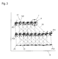
- FIG. 3 shows in a similar representation as FIG. 2 a simulated movement of a harrow 1 when using the method according to the application for determining the position.
- the device 1 is started at the bottom left in the illustrated space 13 and has moved on the illustrated meander-shaped path.
- the positions P1 to P10 are determined either only by odometric methods or additionally by means of a correction on the basis of previously recorded images on the same track section or distance measurements to a straight wall section, the following positions from P11 by odometric methods, corrected using here also simulated image comparisons ( local visual homing).
- the particle cloud represents a distribution for the residence probabilities of the device, which is updated by a so-called particle filter.
- another distribution for the residence probabilities may form the basis for the position estimate.
- a so-called Kalman filter can be used, in which the position uncertainty is described by one or more multivariate Gaussian distributions. In general, such methods are also referred to as Bayes filters.
Abstract
Description
Die Erfindung betrifft ein Verfahren zur Positionsbestimmung bei einem selbstfahrenden Bodenbearbeitungsgerät, das eine Antriebseinheit, eine Steuereinrichtung zur Steuerung der Antriebseinheit und mindestens eine Vorrichtung zur Aufnahme von Bildern einer Umgebung des Bodenbearbeitungsgeräts aufweist.The invention relates to a method for position determination in a self-propelled soil cultivation device, which has a drive unit, a control device for controlling the drive unit and at least one device for receiving images of an environment of the soil cultivation device.
Die Erfindung betrifft weiterhin ein selbstfahrendes Bodenbearbeitungsgerät, das ein derartiges Verfahren zur Positionsbestimmung bei seiner Navigation über den Boden durchführt.The invention further relates to a self-propelled soil cultivation implement, which performs such a method for determining the position during its navigation over the ground.
Selbstfahrende Bodenbearbeitungsgeräte dienen der automatisierten Bearbeitung, beispielsweise Reinigung, von Flächen, ohne dass sie von einem Benutzer geschoben oder geführt werden müssen. Zu solchen selbstfahrenden Bodenbearbeitungsgeräten zählen für den Innenbereich beispielsweise selbstfahrende Staubsauger, auch Saugroboter genannt. Weiterhin werden für den Innenbereich selbstfahrende Reinigungsgeräte zum Wischen von Bodenbelägen eingesetzt. Für den Außenbereich sind als selbstfahrende Bodenbearbeitungsgeräte Mähroboter zum Rasenmähen bekannt und, für eine landwirtschaftliche Nutzung, selbstständig arbeitende Landwirtschaftsmaschinen, beispielsweise zum Pflügen, Säen oder Ernten von großen Feldern. Zur Steuerung von selbstständig arbeitenden Landwirtschaftsmaschinen auf entsprechend großen Flächen hat sich eine Navigation der Geräte über die zu bearbeitende Fläche mittels Satelliten, z.B. GPS (Global Positioning System), etabliert. Für Innenanwendungen oder auch Außenanwendungen in einem kleineren, häuslichen Rahmen ist die mit diesem System erzielbare Genauigkeit jedoch nicht ausreichend.Self-propelled tillage machines are used for automated processing, such as cleaning of surfaces, without having to be pushed or guided by a user. Self-propelled vacuum cleaners, also referred to as vacuum robots, are used for such self-propelled soil cultivation devices for indoor use. Furthermore, for the interior self-propelled cleaning equipment used for wiping of floor coverings. For outdoor use are known as self-propelled tillage mower robots for lawn mowing and, for agricultural use, independently operating agricultural machinery, such as plowing, sowing or harvesting of large fields. For controlling autonomously operating agricultural machines on correspondingly large areas, it has been possible to navigate the equipment over the surface to be processed by means of satellites, e.g. GPS (Global Positioning System), established. However, for indoor or outdoor use in a smaller, domestic environment, the accuracy achievable with this system is not sufficient.
Selbstfahrende Bodenbearbeitungsgeräte für kleinere Flächen weisen üblicherweise einen oder mehrere Sensoren auf, um die Bewegung des Geräts über die zu bearbeitende Fläche zu kontrollieren, beispielsweise um einen Zusammenstoß mit Hindernissen zu vermeiden. Solche Sensoren können beispielsweise Tast- oder Ultraschallsensoren oder auch optische Sensoren sein. Nur in einem Nahbereich arbeitende Sensoren dienen meist der Vermeidung von Zusammenstößen mit Hindernissen, wohingegen Sensoren mit einer größeren Erfassungsreichweite, beispielsweise die eingangs genannte Kamera zur Aufnahme von Umgebungsbildern, auch zur Navigation des Geräts, also zur Planung einer koordinierten Bewegung des Geräts über die zu bearbeitende Fläche, eingesetzt werden. Bei der koordinierten Bewegung soll beispielsweise sichergestellt werden, dass die gesamte Fläche bearbeitet wird, ohne dass Bereiche der Fläche mehrfach überfahren werden.Self-propelled tillage machines for smaller areas usually have one or more sensors to control the movement of the device over the area to be worked, for example to avoid colliding with obstacles. Such sensors may be, for example, tactile or ultrasonic sensors or optical sensors. Only sensors operating in a close range are usually used to avoid collisions with obstacles, whereas sensors with a larger detection range, for example the camera mentioned at the beginning for taking environmental images, also for navigation of the device, ie for planning a coordinated movement of the device over the object to be processed Surface, are used. In the coordinated movement, for example, it should be ensured that the entire surface is processed without repeatedly overrunning areas of the surface.
Aus der Druckschrift
Nachteilig bei dem Verfahren ist jedoch, dass zwar ein paralleles Abfahren von Bahnteilstücken erreicht wird, jedoch keine absoluten Positionsdaten bei der Navigation des Bodenbearbeitungsgeräts bereitstehen. Eine Korrektur erfolgt jeweils mithilfe von zuvor aufgenommenen Bildern, wobei deren absolute Position ebenfalls nicht bekannt ist. Somit summieren sich im Laufe des Verfahrens Fehler in zunehmender, aber nicht bekannter Größe auf. Mit fortschreitendem Verfahren steigt somit die Ungenauigkeit in der Positionsbestimmung, ohne dass eine Abschätzung der Größe dieser Ungenauigkeit möglich ist. Eine Kenntnis der Ungenauigkeit bei der Navigation kann jedoch vorteilhaft sein, beispielsweise um bei zu großer Ungenauigkeit in der Positionsbestimmung alternative Positionsbestimmungsverfahren ausführen zu können, die im normalen Betrieb aber, z.B. aus Effizienzgründen, möglichst selten verwendet werden sollten.A disadvantage of the method, however, is that although a parallel traversing of Bahnteilstücken is achieved, but are not available absolute position data in the navigation of the harrow. A correction is made using previously captured images, with their absolute position also unknown. Thus, in the course of the process, errors accumulate in increasing but unknown size. As the method progresses, the inaccuracy in position determination thus increases without it being possible to estimate the magnitude of this inaccuracy. A knowledge of the inaccuracy in the navigation, however, may be advantageous, for example, to be able to perform alternative positioning in case of excessive inaccuracy in the position determination, but in normal operation, for example, for efficiency reasons, should be used as rarely as possible.
Des Weiteren können bei einem Abfahren einer mäanderförmigen Bahn bei dem genannten bekannten Verfahren Abweichungen von einer idealen geraden Reihe auf einem vorhergehenden Bahnabschnitt zu Abweichungen auf dem folgenden Bahnabschnitt führen, da nur der Abstand zur Vorgängerreihe, aber keine vollständige Positionsschätzung bestimmt wird. Zudem ist eine Erweiterung auf mehrere aneinandergrenzende Bereiche, die jeweils mäanderförmig gereinigt werden, ohne eine vollständige Positionsschätzung nur schwer möglich.Furthermore, when driving down a meander-shaped path in the mentioned known method, deviations from an ideal straight line on a preceding track section can lead to deviations on the following track section, since only the distance to the previous row, but not a complete position estimate, is determined. In addition, an extension to several adjoining areas, each of which is meandered, is difficult to achieve without a complete position estimate.
Ein weiteres Navigationsverfahren für ein selbstfahrendes Bodenbearbeitungsgerät wird in der Druckschrift
Hierbei kann es sich als problematisch erweisen, dass bei Aufnahme eines Bildes bereits eine Auswahl getroffen werden muss, welches Bildmuster eine Landmarke darstellt und wie viele solcher Landmarken identifiziert und gespeichert werden sollen. Dabei stellt sich unter Umständen erst im Nachhinein, nämlich bei einem Wiedersuchen der Landmarken in nachfolgenden Bildern, heraus, ob ausreichend viele geeignete Landmarken zur Positionsbestimmung oder-korrektur bereitstehen. Zudem wird eine Landmarke mit ihrer absoluten Position im Raum gespeichert. Ein Fehler bzw. eine Ungenauigkeit bei der Bestimmung der Landmarkenposition beim ersten Identifizieren der Landmarke beeinflusst damit alle nachfolgenden Positionsbestimmungen bzw. -korrekturen.In this case, it can prove to be problematic that, when taking a picture, a selection must already be made as to which image pattern represents a landmark and how many such landmarks are to be identified and stored. Under certain circumstances, in hindsight, namely when the landmarks are searched again in subsequent images, it may turn out that there are enough suitable landmarks available for position determination or correction. In addition, a landmark with its absolute position is stored in the room. An error or an inaccuracy in determining the landmark position when first identifying the landmark thus affects all subsequent position determinations or corrections.
Es ist eine Aufgabe der vorliegenden Erfindung, ein Verfahren zur Positionsbestimmung bei einem selbstfahrenden Bodenbearbeitungsgerät der eingangs genannten Art zu schaffen, bei dem jederzeit zum einen absolute Positionsdaten für das Gerät, und zum anderen auch ein Maß für die Unsicherheit, mit der diese Positionsdaten behaftet sind, vorliegen. Weiterhin soll das Verfahren dynamisch dahingehend sein, dass im Laufe des Verfahrens ermittelte Informationen und getroffene Entscheidungen möglichst keine nachteiligen und unkorrigierbaren Implikationen für nachfolgende Verfahrensschritte haben. Erfindungsgemäß wird dieses Problem durch ein Verfahren und ein Bodenbearbeitungsgerät mit den Merkmalen des Patentanspruchs 1 bzw. 15 gelöst.It is an object of the present invention to provide a method for determining the position in a self-propelled soil cultivation device of the type mentioned, in which at any time for an absolute position data for the device, and on the other hand, a measure of the uncertainty with which these position data are afflicted , present. Furthermore, the method should be dynamic in that information and decisions made in the course of the method have as far as possible no disadvantageous and uncorrectable implications for subsequent method steps. According to the invention, this problem is solved by a method and a soil cultivation device having the features of
Bei einem erfindungsgemäßen Verfahren zur Positionsbestimmung bei einem selbstfahrenden Bodenbearbeitungsgerät, das eine Antriebseinheit, eine Steuereinrichtung zur Steuerung der Antriebseinheit und eine Vorrichtung zur Aufnahme von Bildern einer Umgebung des Bodenbearbeitungsgeräts aufweist, wird eine aktuelle Position des Bodenbearbeitungsgeräts in Form einer Verteilung von Aufenthaltswahrscheinlichkeiten nachgehalten. Das Verfahren weist die folgenden Schritte auf: Es wird eine aktuelle Position des Bodenbearbeitungsgeräts durch Weiterentwicklung einer eine vorherige Position des Bodenbearbeitungsgeräts beschreibenden Verteilung der Aufenthaltswahrscheinlichkeiten vorhergesagt. Weiter wird ein aktuelles Umgebungsbild aufgenommen. Das aktuelle Umgebungsbild wird mit zumindest einem gespeicherten Umgebungsbild, das an einer vorherigen Position des Bodenbearbeitungsgeräts aufgenommen wurde, verglichen. Die die aktuelle Position beschreibende Verteilung der Aufenthaltswahrscheinlichkeiten wird dann anhand eines Ergebnisses des Vergleichs des aktuellen Umgebungsbildes mit dem zumindest einen Umgebungsbild korrigiert, und es werden die korrigierte Verteilung der Aufenthaltswahrscheinlichkeiten sowie das aktuelle Umgebungsbild gespeichert.In a method according to the invention for determining the position in a self-propelled soil cultivation device which has a drive unit, a control unit for controlling the drive unit and a device for taking pictures of an environment of the tillage implement, a current position of the soil cultivation device is tracked in the form of a distribution of residence probabilities. The method comprises the following steps: A current position of the soil cultivation device is predicted by further development of a distribution of the habitat probabilities describing a previous position of the soil cultivation device. Furthermore, a current environment image is recorded. The current environment image is compared with at least one stored environmental image taken at a previous position of the tillage implement. The distribution of the residence probabilities describing the current position is then corrected on the basis of a result of the comparison of the current environmental image with the at least one environmental image, and the corrected distribution of the residence probabilities as well as the current environmental image are stored.
Durch die Weiterentwicklung und Korrektur der Verteilung von Aufenthaltswahrscheinlichkeiten liefert das Verfahren zu jeder Zeit eine (relativ zur Startposition) absolute Position des Geräts, einschließlich Informationen über die Genauigkeit, mit der die Position angegeben werden kann. Der Vergleich mit Bildern, denen jeweils auch absolute Positionsangaben zugeordnet sind, verringert insgesamt die Unsicherheiten in der Positionsbestimmung. Auf Basis dieser Informationen kann eine systematische Abfahrt eines Bodenbereichs geplant und durchgeführt werden. Gegenüber einer bei einem Bildvergleich nur relativ geschätzten Position (z.B. nur Bestimmung des Abstands zur Vorgängerbahn) werden durch Fehlerfortpflanzung hervorgerufene systematische Fehler verringert. Die bei der Fahrt ständig vorliegende Positionsinformation ermöglicht zudem das inkrementelle Anlegen einer Karte des abgefahrenen Bereichs. Da die Bilder selbst und nicht aus den Bildern extrahierte Informationen wie Landmarken gespeichert werden, steht in nachfolgenden Schritten der volle Informationsgehalt, der an einer vorherigen Position bei der Aufnahme des Bildes vorlag, zur Verfügung. Der Vergleich des aktuellen Umgebungsbildes mit dem zumindest einem gespeicherten Umgebungsbild kann so auf Bildinformationen zurückgreifen, die in einem Landmarken-basierten Verfahren unter Umständen zum Zeitpunkt der Aufnahme des gespeicherten Bildes nicht als relevant identifiziert und damit nicht extrahiert und gespeichert worden wären.By further developing and correcting the distribution of probabilities of residence, the method provides at all times a (relative to the starting position) absolute position of the device, including information about the accuracy with which the position can be given. The comparison with images, which are also assigned absolute position information, reduces the overall uncertainties in the position determination. On the basis of this information, a systematic departure of a ground area can be planned and carried out. In contrast to a position which is only relatively estimated in an image comparison (eg only determination of the distance to the preceding track), systematic errors caused by error propagation are reduced. The position information that is constantly present during the journey also makes it possible to apply a map of the worn area incrementally. Since the images themselves and not information extracted from the images, such as landmarks, are stored in subsequent steps, the full information content that was present at a previous position when the image was captured is available. The comparison of the current environment image with the at least one stored environment image can thus resort to image information that might not have been identified as relevant in a landmark-based process at the time of recording the stored image and thus would not have been extracted and stored.
In einer vorteilhaften Ausgestaltung des Verfahrens umfasst die Position neben einer Ortsinformation auch eine Orientierungsinformation. Auf diese Weise kann neben dem Ort, beispielsweise angegeben in kartesischen Koordinaten, auch die Orientierung (Ausrichtung) des Bodenbearbeitungsgeräts, beispielsweise angegeben im Bezug auf eine Achse in dem Koordinatensystem der Ortsinformation, ständig und mit einer Genauigkeitsangabe versehen geschätzt werden.In an advantageous embodiment of the method, the position comprises not only location information but also orientation information. In this way, in addition to the location, for example given in Cartesian coordinates, also the orientation (orientation) of the harrow, for example given with respect to an axis in the coordinate system of the location information, can be estimated constantly and provided with an accuracy indication.
In einer weiteren vorteilhaften Ausgestaltung des Verfahrens wird die Verteilung der Aufenthaltswahrscheinlichkeiten durch eine Partikelwolke angegeben, die eine Mehrzahl von möglichen Zuständen des Bodenbearbeitungsgeräts umfasst, von denen jeder eine Ortsinformation, eine Orientierungsinformation und eine Wahrscheinlichkeitsinformation enthält. Gegenüber anderen möglichen Repräsentationen der Verteilung der Aufenthaltswahrscheinlichkeiten, beispielsweise einer multivariaten Gaußverteilung, bietet eine Partikelwolke den Vorteil, dass beliebige Verteilungen modelliert werden können. Die Ausbreitung der Partikelwolke spiegelt die Unsicherheit bei der Positionsbestimmung wider.In a further advantageous embodiment of the method, the distribution of the probabilities of residence is indicated by a particle cloud comprising a plurality of possible states of the soil cultivation device, each of which contains location information, orientation information and probability information. Compared with other possible representations of the distribution of the probabilities of residence, for example a multivariate Gaussian distribution, a particle cloud offers the advantage that any distributions can be modeled. The spread of the particle cloud reflects the uncertainty in determining the position.
In einer weiteren vorteilhaften Ausgestaltung des Verfahrens beruht die Weiterentwicklung einer eine vorherige Position des Bodenbearbeitungsgeräts beschreibenden Verteilung der Aufenthaltswahrscheinlichkeiten auf einem odometrischen Verfahren. Besonders bevorzugt werden dabei Fahrinformationen des Geräts, die von Sensoren bereitgestellt werden, verwendet. Ein solches odometrisches Verfahren kann mit geringem sensorischen und rechnerischen Aufwand durchgeführt werden. Letztlich beruht die Positionsbestimmung damit auf einer Kombination von Fahrinformationen und Bildvergleichen (optische Informationen), also auf Informationen, die auf unterschiedliche Art ermittelt werden, wodurch die Güte und Zuverlässigkeit der Positionsbestimmung erhöht werden.In a further advantageous embodiment of the method, the further development of a distribution of the probabilities of residence describing a previous position of the soil cultivation device is based on an odometric method. Driving information of the device, which is provided by sensors, is particularly preferably used. Such an odometric method can be carried out with low sensory and computational effort. Ultimately, the positioning is thus based on a combination of driving information and image comparisons (optical information), that is, on information that is determined in different ways, whereby the quality and reliability of positioning are increased.
In einer weiteren vorteilhaften Ausgestaltung des Verfahrens wird das aktuelle Umgebungsbild mit einem oder mehreren gespeicherten Umgebungsbildern verglichen, wobei Richtungsvektoren bestimmt werden, die eine Richtung angeben, unter der die aktuelle Position, an der das aktuelle Umgebungsbild aufgenommen wurde, von der jeweiligen Position, an der das entsprechende gespeicherte Umgebungsbild aufgenommen wurde, aus betrachtet erscheint. Bevorzugt werden dabei auch Orientierungsdifferenzen bestimmt, die einen Unterschied zwischen einer aktuellen Orientierung des Bodenbearbeitungsgeräts und dessen Orientierung zum Zeitpunkt der Aufnahme eines gespeicherten Umgebungsbilds angeben. Richtungsvektoren und Orientierungsdifferenzen können mit relativ geringem Rechenaufwand und mit großer Genauigkeit aus den Bildvergleichen ermittelt werden. Mithilfe von trigonometrischen Methoden kann dann anhand von den Richtungsvektoren und Orientierungsdifferenzen, gewonnen aus dem Vergleich des aktuellen Umgebungsbildes mit den gespeicherten Umgebungsbildern, eine Korrektur der Verteilung der Aufenthaltswahrscheinlichkeiten erfolgen.In a further advantageous embodiment of the method, the current environmental image is compared with one or more stored environmental images, wherein direction vectors are determined which indicate a direction under which the current position at which the current environmental image was taken from the respective position at which the corresponding stored environmental image was taken, as viewed from. Orientation differences are also preferably determined which indicate a difference between a current orientation of the soil cultivation device and its orientation at the time of recording a stored environmental image. Direction vectors and orientation differences can be determined from the image comparisons with relatively little computational effort and with great accuracy. By using trigonometric methods can then be determined from the directional vectors and orientation differences, obtained by comparing the current environment image with the stored environmental images, a correction of the distribution of the residence probabilities.
Weitere vorteilhafte Ausgestaltungen und Weiterbildungen der Erfindung ergeben sich aus den Unteransprüchen.Further advantageous embodiments and modifications of the invention will become apparent from the dependent claims.
Ein erfindungsgemäßes selbstfahrendes Bodenbearbeitungsgerät weist eine Antriebseinheit, eine Steuereinrichtung zur Steuerung der Antriebseinheit und eine Vorrichtung zur Aufnahme von Bildern einer Umgebung des Bodenbearbeitungsgeräts auf und zeichnet sich dadurch aus, dass es zur Durchführung eines zuvor beschriebenen Verfahrens zur Positionsbestimmung eingerichtet ist. Es ergeben sich die im Zusammenhang mit dem Verfahren genannten Vorteile.An inventive self-propelled soil cultivation device has a drive unit, a control device for controlling the drive unit and a device for recording images of an environment of the soil cultivation device and is characterized in that it is set up for carrying out a method for determining position described above. This results in the advantages mentioned in connection with the method.
Die Erfindung wird nachfolgend anhand von drei Figuren näher erläutert. Die Figuren zeigen:
Figur 1- eine schematische Darstellung eines Bodenbearbeitungsgeräts zur Durchführung des erfindungsgemäßen Verfahrens;
Figur 2- eine schematische Darstellung eines Teils einer von dem Bodenbearbeitungsgerät abgefahrenen Bahnkurve und
Figur 3- einen Abschnitt einer Bahnkurve, die ein simuliertes Bodenbearbeitungsgerät bei Durchführung des erfindungsgemäßen Verfahrens ausführt.
- FIG. 1
- a schematic representation of a cultivator for performing the method according to the invention;
- FIG. 2
- a schematic representation of a part of a traversed by the harrow trajectory and
- FIG. 3
- a section of a trajectory that executes a simulated soil cultivation implement in carrying out the method according to the invention.
Das Bodenbearbeitungsgerät 1, nachfolgend der einfacheren Darstellung halber auch Gerät 1 genannt, weist im Bereich einer Bodenplatte 3 eines Gehäuses 2 angeordnete Antriebsräder 4 auf. Es sind zwei dieser Antriebsräder 4 vorgesehen, die unabhängig voneinander von jeweils einem Antriebsmotor 5 gedreht werden können. Zudem ist als Teil des Fahrwerks ein Stützrad 6 vorhanden. Die beiden Antriebsräder 4 können bezüglich ihrer Drehzahl und auch Drehrichtung unabhängig voneinander angetrieben werden, was auch als differentielle Lenkung bezeichnet wird. Für jedes dieser Antriebsräder ist ein Sensor 7 vorgesehen, der die Drehbewegung des jeweiligen Antriebsrads 4 erfasst. Der Sensor 7 kann beispielsweise ein optischer Drehimpulsgeber sein.The tillage implement 1, hereinafter also called
Weiter ist eine Steuereinrichtung 8 vorhanden, die mit den Antriebsmotoren 5 in Verbindung steht und diese ansteuert. Die Steuereinrichtung 8 weist weiterhin Steuereingänge auf, mit denen sie mit den Sensoren 7 verbunden ist. Weiterhin sind einer oder mehrere Abstandssensoren 9 vorhanden, die am Umfang des Geräts 1 und/oder im Bereich der Bodenplatte 2 angeordnet sind und die ebenfalls mit der Steuereinrichtung 8 verbunden sind. Mithilfe der Abstandssensoren 9, von denen in der
Weiterhin ist bei dem Bodenbearbeitungsgerät 1 eine Kamera 10 als Vorrichtung zur Aufnahme eines Umgebungsbildes vorgesehen, beispielsweise ein CCD (Charge-Coupled Device)-Chip mit geeigneter räumlicher und zeitlicher Auflösung. Auf der nach oben gerichteten optischen Achse 11 der Kamera 10 ist ein hyperbolischer Spiegel 12 angeordnet. Auf diese Weise kann ein 360°-Panoramabild von der Umgebung des Roboters 1 mit einer Kameraaufnahme erfasst und zur weiteren Auswertung an den Steuerrechner 8 weitergegeben werden. Es wird angemerkt, dass anstelle des dargestellten hyperbolischen Spiegels 12 andere Vorrichtungen zur Aufnahme einer möglichst weitwinkligen Aufnahme der Umgebung des Geräts 1 verwendet werden können. Beispielsweise können eine oder mehrere mit Weitwinkel- oder Fisheye-Objektiven versehene Kameras eingesetzt werden. Auch eine drehbare Kamera ist denkbar, ebenso wie eine Laser-Scaneinheit, die beispielsweise mithilfe eines rotierenden Spiegels ein weitwinkliges oder 360°-Panoramabild der Umgebung erfasst.Furthermore, in the
Im Folgenden wird ein erfindungsgemäßes Verfahren zur Positionsbestimmung beschrieben, das beispielsweise von dem in
In
In regelmäßigen Zeitabständen sind bei der Bewegung des Geräts 1 von der Startposition P1 Partikelwolken 14, die die zu dem Zeitpunkt jeweils aktuelle Position des Geräts 1 wiedergeben, gespeichert worden. Diese gespeicherten Positionen sind als Positionen P2 bis P6 in der Figur eingetragen.At regular intervals during the movement of the
Beispielhaft ist in der
Es wird davon ausgegangen, dass beim Start von der Startposition P1 sowohl die Position als auch die Ausrichtung des Geräts 1 bekannt sind, beispielsweise weil die Startposition P1 die Position der Ladestation des Geräts 1 ist, die als Koordinatenursprung definiert ist. Entsprechend sind sowohl die Positionskoordinaten x, y, die Orientierungsinformation θ und die Wahrscheinlichkeitsinformation w aller Partikel 140 der Partikelwolke 14 an der Startposition P1 gleich und auf einen Anfangswert gesetzt. An der Startposition P1 wird nun zunächst ein erstes Umgebungsbild B1 aufgenommen und gespeichert. Weiterhin wird die Startposition P1 in Form der Partikelwolke 14 gespeichert. Die Startposition P1 und das Bild B1 sind dabei einander zugeordnet.It is assumed that when starting from the starting position P1, both the position and the orientation of the
Nach dem Losfahren des Geräts 1 in die Richtung θ wird dann eine aktuelle Position des Geräts 1 parallel zur Bewegung des Geräts in Echtzeit vorhergesagt, indem die Partikelwolke 14 anhand von Fahrinformationen der Sensoren 7 odometrisch weiterentwickelt wird. Hierzu können beispielsweise die bekannten Odometrie-Beziehungen von
Nach einer vorgegebenen Zeit oder nach einer vorgegebenen Wegstrecke wird an einer Position P2 ein weiteres Bild B2 aufgenommen und dieses Bild B2 zusammen mit der aktuell vorliegenden Partikelwolke 14 an dieser Position P2 gespeichert. Die Entwicklung der Partikelwolke 14 erfolgt in diskreten Schritten, wobei zwischen zwei der dargestellten Positionen P1 bis P6, an denen jeweils die Partikelwolke 14 gespeichert wird und ein Bild aufgenommen wird, eine Mehrzahl, beispielsweise 10, Entwicklungsschritte der Partikelwolke 14 liegen können.After a predetermined time or after a predetermined distance, another image B2 is taken at a position P2 and this image B2 is stored together with the currently
Das Verfahren wird mit unveränderter Fahrtrichtung fortgesetzt, bis ein Hindernis vor dem Gerät 1 detektiert wird, beispielsweise über den Abstandssensor 9. Im dargestellten Beispiel ist dieses bei der Position P4 nach dem Abfahren eines ersten, im Wesentlichen geraden Bahnabschnitts der Fall. Dieser erste Bahnabschnitt wird nachfolgend auch als erste Reihe bezeichnet. Vorteilhafterweise kann die erste Reihe entlang einer Wand des Raums 13 verlaufen. In dem Fall können durch seitliche Abstandssensoren 9 bestimme Abstände zur Wand verwendet werden, um eine möglichst gerade erste Reihe zu erhalten. Dabei wird die odometrisch gewonnene Positionsschätzung mithilfe der Abstandssensoren 9 korrigiert. In einer alternativen Ausgestaltung kann auch beim Befahren der ersten Reihe eine Korrektur der Positionsbestimmung nach dem unten beschriebenen Verfahren erfolgen, wobei zuvor in der ersten Reihe aufgenommene Bilder herangezogen werden.The method continues with the direction of travel unchanged until an obstacle is detected in front of the
Es erfolgt dann eine Drehung des Geräts 1 um 90°, hier im Uhrzeigersinn, gefolgt von einer Bewegung um wiederum eine vorgegebene Distanz, die sich beispielsweise an der Breite des Reinigungswerkzeugs orientiert. Während dieses Bahnabschnitts wird wiederum die Partikelwolke 14 weiterentwickelt. Nach einer anschließenden weiteren Drehung um 90° im Uhrzeigersinn wird die Partikelwolke 14 an der dann erreichten Position P5 zusammen mit einem dort aufgenommenen weiteren Bild P5 gespeichert. Das Gerät 1 steht damit am Anfang eines weiteren Bahnabschnitts, von dem in der
Die erste Reihe mit den Positionen P1 bis P4 dient der Aufnahme von ersten Umgebungsbildern B1 bis B4 an den Positionen P1 bis P4, die nur mittels odometrischer Methoden bestimmt werden. Das erfindungsgemäße Verfahren, bei dem odometrische Verfahren mit Korrekturen anhand von Bildvergleichen verknüpft sind, kann bei der weiteren Bewegung des Geräts 1 mithilfe der Bilder B1 bis B4 (und weiterer, im Laufe des Verfahrens aufgenommener Bilder) ausgeführt werden.The first row with the positions P1 to P4 serves to receive first environmental images B1 to B4 at the positions P1 to P4, which are determined only by means of odometric methods. The method according to the invention, in which odometric methods are linked with corrections on the basis of image comparisons, can be used in the following Move the
Bei dem erfindungsgemäßen Verfahren wird nach Aufnahme eines aktuellen Bildes B an der Position P dieses aktuelle Bild B mit einem oder mehreren zuvor aufgenommenen Bildern verglichen, in der
Anhand der Richtungsvektoren 16 und der Orientierungsdifferenzen kann nun die Positionsschätzung in Form der Partikelwolke 14 korrigiert werden. Dabei wird für jedes Partikel 140 der Partikelwolke 14 ermittelt, wie gut dessen Ort 141 und Orientierung 142 zu den Richtungsvektoren 16 und den Orientierungsdifferenzen sowie den Partikelwolken 14 an den Positionen P1 bis P3 passen. Dazu wird jeweils ein erwarteter Richtungsvektor (bzw. eine erwartete Orientierungsdifferenz) mit dem gemessenen Richtungsvektor 16 (bzw. der gemessenen Orientierungsdifferenz) verglichen. Vorteilhafterweise erfolgt eine Korrektur dabei nicht durch Korrektur der Ortsinformationen x, y und der Orientierungsinformation θ der Partikel 140 der Partikelwolke 14, sondern durch eine Neuberechnung der Wahrscheinlichkeitsinformationen w der Partikel 140: Je besser die Position eines Partikels 140 zu den gemessenen Richtungsvektoren 16 und den Orientierungsdifferenzen passt, umso größer ist die Wahrscheinlichkeit w dieses Partikels 140. Umgekehrt wird die Wahrscheinlichkeit w eines Partikels 140 nach der Neuberechnung klein sein, wenn die Position dieses Partikels 140 zu einer schlechten Passung führt.Based on the
Auch die Bestimmung der Richtungsvektoren und Orientierungsdifferenzen ist mit einer Unsicherheit behaftet, einerseits aufgrund der Unsicherheit in den Positionen P2 und P3, andererseits aufgrund von Ungenauigkeiten bei dem Verfahren des lokalen visuellen Homings. Die Größe der Unsicherheit bei der Bestimmung der Richtungsvektoren und Orientierungsdifferenzen kann im Schritt des Korrigierens der Wahrscheinlichkeiten w der Partikel 140 berücksichtigt werden. Nach der Bestimmung der Wahrscheinlichkeiten w aller Partikel 140 werden Partikel 140 mit geringer Wahrscheinlichkeit w aus der Partikelwolke 14 entfernt und dafür Partikel 140 mit höherer Wahrscheinlichkeit w vervielfacht. Durch diesen Schritt verringert sich die Ausdehnung der Partikelwolke 14 und damit die Unsicherheit der Positionsschätzung.Also, the determination of the directional vectors and orientation differences is subject to uncertainty, on the one hand due to the uncertainty in the positions P2 and P3, on the other hand due to inaccuracies in the method of local visual homing. The magnitude of the uncertainty in the determination of the directional vectors and orientation differences can be taken into account in the step of correcting the probabilities w of the
Nach dem Korrigieren der Partikelwolke 14 wird diese als Position P7 zusammen mit dem aktuellen Bild B (als Bild B7) gespeichert, um für nachfolgende Bildvergleiche und Korrekturschritte verfügbar zu sein. Zwischen der Aufnahme des aktuellen Bildes B und der Auswertung des Bildvergleichs und dem erfolgten Korrekturschritt vergeht eine gewisse Zeit, in der das Gerät 1 bereits eine Wegstrecke zurückgelegt hat. Die Korrektur wird auf die zum Zeitpunkt der Bildaufnahme aktuelle Partikelwolke 14 angewendet. Diese ist in der vergangenen Zeit jedoch unter Umständen bereits odometrisch weiterentwickelt worden. Es ist in einem solchen Fall vorteilhaft, die Weiterentwickelung der Partikelwolke 14 ab der dann korrigierten Position neu zu berechnen und so verzögert zu korrigieren.After correcting
Das beschriebene Verfahren liefert mit der aktuellen Partikelwolke zu jeder Zeit eine (relativ zur Startposition) absolute Position (Ort und Orientierung) des Geräts 1 einschließlich Information über die Genauigkeit, mit der Ort und Orientierung angegeben werden können.The method described provides with the current cloud of particles at all times an (relative to the starting position) absolute position (location and orientation) of the
Bei dem dargestellten Verfahren stellt die Partikelwolke eine Verteilung für die Aufenthaltswahrscheinlichkeiten des Geräts dar, die durch einen sogenannten Partikelfilter aktualisiert wird. In alternativen Ausgestaltungen des Verfahrens kann eine andere Verteilung für die Aufenthaltswahrscheinlichkeiten Grundlage für die Positionsschätzung bilden. Beispielsweise kann anstelle des Partikelfilters ein sogenannter Kalmanfilter eingesetzt werden, bei dem die Positionsunsicherheit durch eine oder mehrere multivariate Gaußverteilung beschrieben wird. Allgemein werden derartige Verfahren auch als Bayesfilter bezeichnet.In the illustrated method, the particle cloud represents a distribution for the residence probabilities of the device, which is updated by a so-called particle filter. In alternative embodiments of the method, another distribution for the residence probabilities may form the basis for the position estimate. For example, instead of the particle filter, a so-called Kalman filter can be used, in which the position uncertainty is described by one or more multivariate Gaussian distributions. In general, such methods are also referred to as Bayes filters.
Claims (15)
Applications Claiming Priority (1)
| Application Number | Priority Date | Filing Date | Title |
|---|---|---|---|
| DE102012112037.4A DE102012112037A1 (en) | 2012-12-10 | 2012-12-10 | Self-propelled soil tillage implement and method for determining position in a self-propelled tillage implement |
Publications (3)
| Publication Number | Publication Date |
|---|---|
| EP2741161A2 true EP2741161A2 (en) | 2014-06-11 |
| EP2741161A3 EP2741161A3 (en) | 2017-07-12 |
| EP2741161B1 EP2741161B1 (en) | 2020-03-18 |
Family
ID=49916960
Family Applications (1)
| Application Number | Title | Priority Date | Filing Date |
|---|---|---|---|
| EP13401133.7A Active EP2741161B1 (en) | 2012-12-10 | 2013-12-10 | Autonomous apparatus for processing a surface and method for detecting the position of the autonomous apparatus |
Country Status (2)
| Country | Link |
|---|---|
| EP (1) | EP2741161B1 (en) |
| DE (1) | DE102012112037A1 (en) |
Cited By (1)
| Publication number | Priority date | Publication date | Assignee | Title |
|---|---|---|---|---|
| CN112650207A (en) * | 2019-10-11 | 2021-04-13 | 杭州萤石软件有限公司 | Robot positioning correction method, apparatus, and storage medium |
Families Citing this family (1)
| Publication number | Priority date | Publication date | Assignee | Title |
|---|---|---|---|---|
| DE102019204267A1 (en) * | 2019-03-27 | 2020-10-01 | Robert Bosch Gmbh | Method for controlling at least one autonomous working device |
Citations (2)
| Publication number | Priority date | Publication date | Assignee | Title |
|---|---|---|---|---|
| US20070090973A1 (en) | 2002-12-17 | 2007-04-26 | Evolution Robotics, Inc. | Systems and methods for using multiple hypotheses in a visual simultaneous localization and mapping system |
| DE102007016802B3 (en) | 2007-04-05 | 2008-05-15 | Miele & Cie. Kg | Self-propelled tilling device e.g. robot, navigating method, involves determining driving direction by evaluating determined vectors and by controlling distance to preceding tracks, and forming meander/spiral shaped preset track |
Family Cites Families (1)
| Publication number | Priority date | Publication date | Assignee | Title |
|---|---|---|---|---|
| WO2007051972A1 (en) * | 2005-10-31 | 2007-05-10 | Qinetiq Limited | Navigation system |
-
2012
- 2012-12-10 DE DE102012112037.4A patent/DE102012112037A1/en not_active Ceased
-
2013
- 2013-12-10 EP EP13401133.7A patent/EP2741161B1/en active Active
Patent Citations (2)
| Publication number | Priority date | Publication date | Assignee | Title |
|---|---|---|---|---|
| US20070090973A1 (en) | 2002-12-17 | 2007-04-26 | Evolution Robotics, Inc. | Systems and methods for using multiple hypotheses in a visual simultaneous localization and mapping system |
| DE102007016802B3 (en) | 2007-04-05 | 2008-05-15 | Miele & Cie. Kg | Self-propelled tilling device e.g. robot, navigating method, involves determining driving direction by evaluating determined vectors and by controlling distance to preceding tracks, and forming meander/spiral shaped preset track |
Non-Patent Citations (1)
| Title |
|---|
| R. SIEGWART; R. NOURBAKHSH: "Introduction to Autonomous Mobile Robots", 2004, MIT PRESS |
Cited By (1)
| Publication number | Priority date | Publication date | Assignee | Title |
|---|---|---|---|---|
| CN112650207A (en) * | 2019-10-11 | 2021-04-13 | 杭州萤石软件有限公司 | Robot positioning correction method, apparatus, and storage medium |
Also Published As
| Publication number | Publication date |
|---|---|
| EP2741161A3 (en) | 2017-07-12 |
| EP2741161B1 (en) | 2020-03-18 |
| DE102012112037A1 (en) | 2014-06-12 |
Similar Documents
| Publication | Publication Date | Title |
|---|---|---|
| DE102007016802B3 (en) | Self-propelled tilling device e.g. robot, navigating method, involves determining driving direction by evaluating determined vectors and by controlling distance to preceding tracks, and forming meander/spiral shaped preset track | |
| DE102015119865B4 (en) | Robot-assisted processing of a surface using a robot | |
| DE102012112036B4 (en) | Self-propelled tillage implement and method for navigating a self-propelled tillage implement | |
| EP2977844B1 (en) | Method for cleaning or processing a room using an automatically moved device | |
| EP3659001B1 (en) | Magnetometer for robot navigation | |
| DE60011674T2 (en) | AUTONOMOUS MULTIPLE PLATFORM ROBOT SYSTEM | |
| EP2752726B1 (en) | Floor treatment machine and method for treating floor surfaces | |
| DE102015006014A1 (en) | Soil cultivation device and method for its navigation and swarm of tillage equipment and methods for their joint navigation | |
| EP2812766B2 (en) | Method for automatically triggering a self-positioning process | |
| DE60220435T2 (en) | AUTONOMOUS MACHINE | |
| EP3662229B1 (en) | Method for determining the orientation of a robot, orientation determination apparatus of a robot, and robot | |
| EP3824247A1 (en) | Method and system for determining a position of a vehicle | |
| DE102016121320A1 (en) | Method for operating a self-propelled robot | |
| DE102017127180A1 (en) | Soil cultivation by means of an autonomous mobile robot | |
| DE102019218192A1 (en) | Method of working crops in a field | |
| DE102018113015A1 (en) | Autonomous, mobile work machine | |
| EP2741161B1 (en) | Autonomous apparatus for processing a surface and method for detecting the position of the autonomous apparatus | |
| DE102014110201B3 (en) | Self-propelled robot and obstacle detection method for a self-propelled robot | |
| EP2749983B1 (en) | Device and method for determining position | |
| DE102014208434A1 (en) | Autonomous vehicle and navigation method for an autonomous vehicle for collision avoidance | |
| DE102010029241A1 (en) | Soil cultivation device and method for processing a floor surface | |
| WO2007090557A2 (en) | Method for generating an environmental image | |
| Xue | Guidance of an agricultural robot with variable angle-of-view camera arrangement in cornfield | |
| DE102019204267A1 (en) | Method for controlling at least one autonomous working device | |
| DE102004013811A1 (en) | Surface area automatic covering method in which a vehicle, e.g. a vacuum cleaner, lawn mower or mine detector, is guided on a path by comparing its instantaneous orientation to a characteristic sequence |
Legal Events
| Date | Code | Title | Description |
|---|---|---|---|
| PUAI | Public reference made under article 153(3) epc to a published international application that has entered the european phase |
Free format text: ORIGINAL CODE: 0009012 |
|
| 17P | Request for examination filed |
Effective date: 20131210 |
|
| AK | Designated contracting states |
Kind code of ref document: A2 Designated state(s): AL AT BE BG CH CY CZ DE DK EE ES FI FR GB GR HR HU IE IS IT LI LT LU LV MC MK MT NL NO PL PT RO RS SE SI SK SM TR |
|
| AX | Request for extension of the european patent |
Extension state: BA ME |
|
| PUAL | Search report despatched |
Free format text: ORIGINAL CODE: 0009013 |
|
| RIN1 | Information on inventor provided before grant (corrected) |
Inventor name: MOELLER, RALF Inventor name: DE JONG, JANINA Inventor name: FLEER, DAVID Inventor name: KRZYKAWSKI, MARTIN Inventor name: HILLEN, LORENZ Inventor name: HORST, MICHAEL |
|
| AK | Designated contracting states |
Kind code of ref document: A3 Designated state(s): AL AT BE BG CH CY CZ DE DK EE ES FI FR GB GR HR HU IE IS IT LI LT LU LV MC MK MT NL NO PL PT RO RS SE SI SK SM TR |
|
| AX | Request for extension of the european patent |
Extension state: BA ME |
|
| RIC1 | Information provided on ipc code assigned before grant |
Ipc: G01C 21/00 20060101ALI20170606BHEP Ipc: G05D 1/02 20060101AFI20170606BHEP |
|
| STAA | Information on the status of an ep patent application or granted ep patent |
Free format text: STATUS: REQUEST FOR EXAMINATION WAS MADE |
|
| R17P | Request for examination filed (corrected) |
Effective date: 20171013 |
|
| RBV | Designated contracting states (corrected) |
Designated state(s): AL AT BE BG CH CY CZ DE DK EE ES FI FR GB GR HR HU IE IS IT LI LT LU LV MC MK MT NL NO PL PT RO RS SE SI SK SM TR |
|
| REG | Reference to a national code |
Ref country code: DE Ref legal event code: R079 Ref document number: 502013014456 Country of ref document: DE Free format text: PREVIOUS MAIN CLASS: G05D0001020000 Ipc: G01C0022000000 |
|
| GRAP | Despatch of communication of intention to grant a patent |
Free format text: ORIGINAL CODE: EPIDOSNIGR1 |
|
| STAA | Information on the status of an ep patent application or granted ep patent |
Free format text: STATUS: GRANT OF PATENT IS INTENDED |
|
| RIC1 | Information provided on ipc code assigned before grant |
Ipc: G01C 21/00 20060101ALI20191014BHEP Ipc: G01C 22/00 20060101AFI20191014BHEP Ipc: G05D 1/02 20060101ALI20191014BHEP |
|
| INTG | Intention to grant announced |
Effective date: 20191107 |
|
| GRAS | Grant fee paid |
Free format text: ORIGINAL CODE: EPIDOSNIGR3 |
|
| GRAA | (expected) grant |
Free format text: ORIGINAL CODE: 0009210 |
|
| STAA | Information on the status of an ep patent application or granted ep patent |
Free format text: STATUS: THE PATENT HAS BEEN GRANTED |
|
| AK | Designated contracting states |
Kind code of ref document: B1 Designated state(s): AL AT BE BG CH CY CZ DE DK EE ES FI FR GB GR HR HU IE IS IT LI LT LU LV MC MK MT NL NO PL PT RO RS SE SI SK SM TR |
|
| REG | Reference to a national code |
Ref country code: GB Ref legal event code: FG4D Free format text: NOT ENGLISH |
|
| REG | Reference to a national code |
Ref country code: DE Ref legal event code: R096 Ref document number: 502013014456 Country of ref document: DE |
|
| REG | Reference to a national code |
Ref country code: AT Ref legal event code: REF Ref document number: 1246415 Country of ref document: AT Kind code of ref document: T Effective date: 20200415 Ref country code: IE Ref legal event code: FG4D Free format text: LANGUAGE OF EP DOCUMENT: GERMAN |
|
| PG25 | Lapsed in a contracting state [announced via postgrant information from national office to epo] |
Ref country code: NO Free format text: LAPSE BECAUSE OF FAILURE TO SUBMIT A TRANSLATION OF THE DESCRIPTION OR TO PAY THE FEE WITHIN THE PRESCRIBED TIME-LIMIT Effective date: 20200618 Ref country code: RS Free format text: LAPSE BECAUSE OF FAILURE TO SUBMIT A TRANSLATION OF THE DESCRIPTION OR TO PAY THE FEE WITHIN THE PRESCRIBED TIME-LIMIT Effective date: 20200318 Ref country code: FI Free format text: LAPSE BECAUSE OF FAILURE TO SUBMIT A TRANSLATION OF THE DESCRIPTION OR TO PAY THE FEE WITHIN THE PRESCRIBED TIME-LIMIT Effective date: 20200318 |
|
| REG | Reference to a national code |
Ref country code: NL Ref legal event code: MP Effective date: 20200318 |
|
| PG25 | Lapsed in a contracting state [announced via postgrant information from national office to epo] |
Ref country code: HR Free format text: LAPSE BECAUSE OF FAILURE TO SUBMIT A TRANSLATION OF THE DESCRIPTION OR TO PAY THE FEE WITHIN THE PRESCRIBED TIME-LIMIT Effective date: 20200318 Ref country code: GR Free format text: LAPSE BECAUSE OF FAILURE TO SUBMIT A TRANSLATION OF THE DESCRIPTION OR TO PAY THE FEE WITHIN THE PRESCRIBED TIME-LIMIT Effective date: 20200619 Ref country code: LV Free format text: LAPSE BECAUSE OF FAILURE TO SUBMIT A TRANSLATION OF THE DESCRIPTION OR TO PAY THE FEE WITHIN THE PRESCRIBED TIME-LIMIT Effective date: 20200318 Ref country code: SE Free format text: LAPSE BECAUSE OF FAILURE TO SUBMIT A TRANSLATION OF THE DESCRIPTION OR TO PAY THE FEE WITHIN THE PRESCRIBED TIME-LIMIT Effective date: 20200318 Ref country code: BG Free format text: LAPSE BECAUSE OF FAILURE TO SUBMIT A TRANSLATION OF THE DESCRIPTION OR TO PAY THE FEE WITHIN THE PRESCRIBED TIME-LIMIT Effective date: 20200618 |
|
| REG | Reference to a national code |
Ref country code: LT Ref legal event code: MG4D |
|
| PG25 | Lapsed in a contracting state [announced via postgrant information from national office to epo] |
Ref country code: NL Free format text: LAPSE BECAUSE OF FAILURE TO SUBMIT A TRANSLATION OF THE DESCRIPTION OR TO PAY THE FEE WITHIN THE PRESCRIBED TIME-LIMIT Effective date: 20200318 |
|
| PG25 | Lapsed in a contracting state [announced via postgrant information from national office to epo] |
Ref country code: LT Free format text: LAPSE BECAUSE OF FAILURE TO SUBMIT A TRANSLATION OF THE DESCRIPTION OR TO PAY THE FEE WITHIN THE PRESCRIBED TIME-LIMIT Effective date: 20200318 Ref country code: CZ Free format text: LAPSE BECAUSE OF FAILURE TO SUBMIT A TRANSLATION OF THE DESCRIPTION OR TO PAY THE FEE WITHIN THE PRESCRIBED TIME-LIMIT Effective date: 20200318 Ref country code: RO Free format text: LAPSE BECAUSE OF FAILURE TO SUBMIT A TRANSLATION OF THE DESCRIPTION OR TO PAY THE FEE WITHIN THE PRESCRIBED TIME-LIMIT Effective date: 20200318 Ref country code: EE Free format text: LAPSE BECAUSE OF FAILURE TO SUBMIT A TRANSLATION OF THE DESCRIPTION OR TO PAY THE FEE WITHIN THE PRESCRIBED TIME-LIMIT Effective date: 20200318 Ref country code: SM Free format text: LAPSE BECAUSE OF FAILURE TO SUBMIT A TRANSLATION OF THE DESCRIPTION OR TO PAY THE FEE WITHIN THE PRESCRIBED TIME-LIMIT Effective date: 20200318 Ref country code: SK Free format text: LAPSE BECAUSE OF FAILURE TO SUBMIT A TRANSLATION OF THE DESCRIPTION OR TO PAY THE FEE WITHIN THE PRESCRIBED TIME-LIMIT Effective date: 20200318 Ref country code: IS Free format text: LAPSE BECAUSE OF FAILURE TO SUBMIT A TRANSLATION OF THE DESCRIPTION OR TO PAY THE FEE WITHIN THE PRESCRIBED TIME-LIMIT Effective date: 20200718 Ref country code: PT Free format text: LAPSE BECAUSE OF FAILURE TO SUBMIT A TRANSLATION OF THE DESCRIPTION OR TO PAY THE FEE WITHIN THE PRESCRIBED TIME-LIMIT Effective date: 20200812 |
|
| REG | Reference to a national code |
Ref country code: DE Ref legal event code: R097 Ref document number: 502013014456 Country of ref document: DE |
|
| PLBE | No opposition filed within time limit |
Free format text: ORIGINAL CODE: 0009261 |
|
| STAA | Information on the status of an ep patent application or granted ep patent |
Free format text: STATUS: NO OPPOSITION FILED WITHIN TIME LIMIT |
|
| PG25 | Lapsed in a contracting state [announced via postgrant information from national office to epo] |
Ref country code: ES Free format text: LAPSE BECAUSE OF FAILURE TO SUBMIT A TRANSLATION OF THE DESCRIPTION OR TO PAY THE FEE WITHIN THE PRESCRIBED TIME-LIMIT Effective date: 20200318 Ref country code: DK Free format text: LAPSE BECAUSE OF FAILURE TO SUBMIT A TRANSLATION OF THE DESCRIPTION OR TO PAY THE FEE WITHIN THE PRESCRIBED TIME-LIMIT Effective date: 20200318 Ref country code: IT Free format text: LAPSE BECAUSE OF FAILURE TO SUBMIT A TRANSLATION OF THE DESCRIPTION OR TO PAY THE FEE WITHIN THE PRESCRIBED TIME-LIMIT Effective date: 20200318 |
|
| 26N | No opposition filed |
Effective date: 20201221 |
|
| PG25 | Lapsed in a contracting state [announced via postgrant information from national office to epo] |
Ref country code: PL Free format text: LAPSE BECAUSE OF FAILURE TO SUBMIT A TRANSLATION OF THE DESCRIPTION OR TO PAY THE FEE WITHIN THE PRESCRIBED TIME-LIMIT Effective date: 20200318 |
|
| PG25 | Lapsed in a contracting state [announced via postgrant information from national office to epo] |
Ref country code: SI Free format text: LAPSE BECAUSE OF FAILURE TO SUBMIT A TRANSLATION OF THE DESCRIPTION OR TO PAY THE FEE WITHIN THE PRESCRIBED TIME-LIMIT Effective date: 20200318 |
|
| REG | Reference to a national code |
Ref country code: CH Ref legal event code: PL |
|
| PG25 | Lapsed in a contracting state [announced via postgrant information from national office to epo] |
Ref country code: MC Free format text: LAPSE BECAUSE OF FAILURE TO SUBMIT A TRANSLATION OF THE DESCRIPTION OR TO PAY THE FEE WITHIN THE PRESCRIBED TIME-LIMIT Effective date: 20200318 |
|
| REG | Reference to a national code |
Ref country code: BE Ref legal event code: MM Effective date: 20201231 |
|
| PG25 | Lapsed in a contracting state [announced via postgrant information from national office to epo] |
Ref country code: LU Free format text: LAPSE BECAUSE OF NON-PAYMENT OF DUE FEES Effective date: 20201210 Ref country code: IE Free format text: LAPSE BECAUSE OF NON-PAYMENT OF DUE FEES Effective date: 20201210 |
|
| PG25 | Lapsed in a contracting state [announced via postgrant information from national office to epo] |
Ref country code: LI Free format text: LAPSE BECAUSE OF NON-PAYMENT OF DUE FEES Effective date: 20201231 Ref country code: CH Free format text: LAPSE BECAUSE OF NON-PAYMENT OF DUE FEES Effective date: 20201231 |
|
| REG | Reference to a national code |
Ref country code: AT Ref legal event code: MM01 Ref document number: 1246415 Country of ref document: AT Kind code of ref document: T Effective date: 20201210 |
|
| PG25 | Lapsed in a contracting state [announced via postgrant information from national office to epo] |
Ref country code: AT Free format text: LAPSE BECAUSE OF NON-PAYMENT OF DUE FEES Effective date: 20201210 |
|
| PG25 | Lapsed in a contracting state [announced via postgrant information from national office to epo] |
Ref country code: TR Free format text: LAPSE BECAUSE OF FAILURE TO SUBMIT A TRANSLATION OF THE DESCRIPTION OR TO PAY THE FEE WITHIN THE PRESCRIBED TIME-LIMIT Effective date: 20200318 Ref country code: MT Free format text: LAPSE BECAUSE OF FAILURE TO SUBMIT A TRANSLATION OF THE DESCRIPTION OR TO PAY THE FEE WITHIN THE PRESCRIBED TIME-LIMIT Effective date: 20200318 Ref country code: CY Free format text: LAPSE BECAUSE OF FAILURE TO SUBMIT A TRANSLATION OF THE DESCRIPTION OR TO PAY THE FEE WITHIN THE PRESCRIBED TIME-LIMIT Effective date: 20200318 |
|
| PG25 | Lapsed in a contracting state [announced via postgrant information from national office to epo] |
Ref country code: MK Free format text: LAPSE BECAUSE OF FAILURE TO SUBMIT A TRANSLATION OF THE DESCRIPTION OR TO PAY THE FEE WITHIN THE PRESCRIBED TIME-LIMIT Effective date: 20200318 Ref country code: AL Free format text: LAPSE BECAUSE OF FAILURE TO SUBMIT A TRANSLATION OF THE DESCRIPTION OR TO PAY THE FEE WITHIN THE PRESCRIBED TIME-LIMIT Effective date: 20200318 |
|
| PG25 | Lapsed in a contracting state [announced via postgrant information from national office to epo] |
Ref country code: BE Free format text: LAPSE BECAUSE OF NON-PAYMENT OF DUE FEES Effective date: 20201231 |
|
| PGFP | Annual fee paid to national office [announced via postgrant information from national office to epo] |
Ref country code: GB Payment date: 20221220 Year of fee payment: 10 Ref country code: FR Payment date: 20221222 Year of fee payment: 10 Ref country code: DE Payment date: 20221231 Year of fee payment: 10 |