EP2741105A2 - Vehicle body part - Google Patents
Vehicle body part Download PDFInfo
- Publication number
- EP2741105A2 EP2741105A2 EP13193168.5A EP13193168A EP2741105A2 EP 2741105 A2 EP2741105 A2 EP 2741105A2 EP 13193168 A EP13193168 A EP 13193168A EP 2741105 A2 EP2741105 A2 EP 2741105A2
- Authority
- EP
- European Patent Office
- Prior art keywords
- layer
- electrically conductive
- body part
- conductive layer
- heating
- Prior art date
- Legal status (The legal status is an assumption and is not a legal conclusion. Google has not performed a legal analysis and makes no representation as to the accuracy of the status listed.)
- Withdrawn
Links
Images


Classifications
-
- G—PHYSICS
- G01—MEASURING; TESTING
- G01S—RADIO DIRECTION-FINDING; RADIO NAVIGATION; DETERMINING DISTANCE OR VELOCITY BY USE OF RADIO WAVES; LOCATING OR PRESENCE-DETECTING BY USE OF THE REFLECTION OR RERADIATION OF RADIO WAVES; ANALOGOUS ARRANGEMENTS USING OTHER WAVES
- G01S13/00—Systems using the reflection or reradiation of radio waves, e.g. radar systems; Analogous systems using reflection or reradiation of waves whose nature or wavelength is irrelevant or unspecified
- G01S13/88—Radar or analogous systems specially adapted for specific applications
- G01S13/93—Radar or analogous systems specially adapted for specific applications for anti-collision purposes
- G01S13/931—Radar or analogous systems specially adapted for specific applications for anti-collision purposes of land vehicles
-
- G—PHYSICS
- G01—MEASURING; TESTING
- G01S—RADIO DIRECTION-FINDING; RADIO NAVIGATION; DETERMINING DISTANCE OR VELOCITY BY USE OF RADIO WAVES; LOCATING OR PRESENCE-DETECTING BY USE OF THE REFLECTION OR RERADIATION OF RADIO WAVES; ANALOGOUS ARRANGEMENTS USING OTHER WAVES
- G01S7/00—Details of systems according to groups G01S13/00, G01S15/00, G01S17/00
- G01S7/02—Details of systems according to groups G01S13/00, G01S15/00, G01S17/00 of systems according to group G01S13/00
- G01S7/03—Details of HF subsystems specially adapted therefor, e.g. common to transmitter and receiver
-
- G—PHYSICS
- G01—MEASURING; TESTING
- G01S—RADIO DIRECTION-FINDING; RADIO NAVIGATION; DETERMINING DISTANCE OR VELOCITY BY USE OF RADIO WAVES; LOCATING OR PRESENCE-DETECTING BY USE OF THE REFLECTION OR RERADIATION OF RADIO WAVES; ANALOGOUS ARRANGEMENTS USING OTHER WAVES
- G01S13/00—Systems using the reflection or reradiation of radio waves, e.g. radar systems; Analogous systems using reflection or reradiation of waves whose nature or wavelength is irrelevant or unspecified
- G01S13/88—Radar or analogous systems specially adapted for specific applications
- G01S13/93—Radar or analogous systems specially adapted for specific applications for anti-collision purposes
- G01S13/931—Radar or analogous systems specially adapted for specific applications for anti-collision purposes of land vehicles
- G01S2013/9327—Sensor installation details
- G01S2013/93275—Sensor installation details in the bumper area
-
- G—PHYSICS
- G01—MEASURING; TESTING
- G01S—RADIO DIRECTION-FINDING; RADIO NAVIGATION; DETERMINING DISTANCE OR VELOCITY BY USE OF RADIO WAVES; LOCATING OR PRESENCE-DETECTING BY USE OF THE REFLECTION OR RERADIATION OF RADIO WAVES; ANALOGOUS ARRANGEMENTS USING OTHER WAVES
- G01S7/00—Details of systems according to groups G01S13/00, G01S15/00, G01S17/00
- G01S7/02—Details of systems according to groups G01S13/00, G01S15/00, G01S17/00 of systems according to group G01S13/00
- G01S7/027—Constructional details of housings, e.g. form, type, material or ruggedness
-
- G—PHYSICS
- G01—MEASURING; TESTING
- G01S—RADIO DIRECTION-FINDING; RADIO NAVIGATION; DETERMINING DISTANCE OR VELOCITY BY USE OF RADIO WAVES; LOCATING OR PRESENCE-DETECTING BY USE OF THE REFLECTION OR RERADIATION OF RADIO WAVES; ANALOGOUS ARRANGEMENTS USING OTHER WAVES
- G01S7/00—Details of systems according to groups G01S13/00, G01S15/00, G01S17/00
- G01S7/02—Details of systems according to groups G01S13/00, G01S15/00, G01S17/00 of systems according to group G01S13/00
- G01S7/40—Means for monitoring or calibrating
- G01S7/4004—Means for monitoring or calibrating of parts of a radar system
- G01S7/4039—Means for monitoring or calibrating of parts of a radar system of sensor or antenna obstruction, e.g. dirt- or ice-coating
- G01S7/4043—Means for monitoring or calibrating of parts of a radar system of sensor or antenna obstruction, e.g. dirt- or ice-coating including means to prevent or remove the obstruction
Definitions
- the invention relates to a body part for a motor vehicle according to the type of claim 1.
- sensors are installed in body parts, which serve, for example, the distance measurement. Such sensors may be installed in a front and / or rear bumper and, during parking, detect the distance to an obstacle, another vehicle. Such systems are known as PDC sensors.
- Known sensors of this type are embedded in apertures of bumpers and painted with one of the color of the vehicle, the bumper.
- An example of a embedded in a body part, a bumper or a bumper PDC sensor shows the DE 103 14 862 A1 ,
- the DE 10 2011 107 216 A1 describes a radome of a transmitting and receiving device for radar waves in a motor vehicle.
- a heating device is arranged flat between a base layer and a cover layer.
- the heating device is designed as an electrically conductive paint.
- the prior art solution provides the transmit and receive active end of the sensor with a heater.
- the sensor is received in an opening of the body part, the bumper and thus visible from the outside.
- the object of the present invention is to provide a body part for a sensor receptacle in relation to the known versions of improved design.
- the invention proposes a body part for a motor vehicle, in particular in the form of a bumper or a bumper, wherein the body part is made of a plastic and has on its back a surface for a rear attachable sensor, preferably a radar sensor, said surface is a heater in Form associated with an electrically conductive layer.
- the area to be heated in a plastic component is realized with two opposing electrodes and a resistance heating element located between the electrodes (surface heating element).
- the resistance heating element, the heating layer consists of a viscous (pourable, pressure, spreadable) reactive liquid which cures in a short time either thermally or with UV action.
- the heating device realized in accordance with the invention - the flat application, the flat layer which is flowed through in the layer thickness and over the surface of current - has the advantage of a much less sensitive design and at the same time a very flat heating effect compared with a heating foil design applied directly to a film or directly.
- the conductive layer of the heating device according to the invention can be applied as a continuous surface, but also in narrow, mutually insulated strips.
- the electrically conductive layer is formed as a conductive particles having, consisting of such particles paint, a viscous paste.
- the resistance of the layer can be determined by additions of carbon in the form of nano-tubes specifically set.
- the layer is preferably spread or applied by screen printing.
- a preferred development of the invention provides a protective layer above the heating layer, thus completely covering it. This will make the heating layer damaging influences, in particular by salt avoided.
- the coating can be applied directly to the plastic component, the back of the plastic bumper.
- the coating, the heating layer can also be applied to a film or between two films.
- the film (s) then act as a sealing layer.
- the energization of the heating layer via two linear electrodes formed which frame the surface of the heating layer opposite each other.
- the connection of the electrode wires is via a plug-in system, which is designed in the form of plug contacts and corresponds to an automotive standard.
- a separate electronic component provides the control of the current intensity, in particular depending on the driving condition and / or the temperature.
- the contacting of the electrodes can be realized via a mounted on the back of the component to be heated frame with integrated / cast-in connector.
- the contacting can be done by crimping or embossing the electrode with electrical lines.
- the contact between frame and electrodes can be realized by integrated, conductive teeth in the frame, which press into the electrode path by pressing the frame onto the electrodes.
- the layer of the heater is embedded in a recess of the plastic component.
- the layer thickness of the component is in this case reduced such that the desired radiation characteristic results, the required transmission and receiving radiation intensity is achieved, the required Abtau nie is achieved.
- the layer thickness of the heating layer is chosen such that on the one hand the required heating power results, on the other hand no Restriction of the sensor function is done.
- the electrically conductive layer of the heating device can also be realized by rendering the plastic electrically conductive in the intended area by adding conductive particles, for example carbon nanotubes.
- a development of the invention provides that the rear side of the body part is thinned in exactly the surface area which corresponds to the top surface of the sensor.
- An embodiment of the invention provides that the sensor is attached by means of a holder on the back of the body part, the bumper.
- the body part, the bumper may have rear locking elements or fastening elements, via which the sensor together with a holder receiving it is attachable.
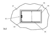
- the FIG. 1 shows in plan view a part of the back of a plastic bumper SF.
- the back of the bumper SF is covered with an electrically conductive layer HZ.
- the electrically conductive layer HZ is provided with two frame-shaped electrodes EK, via which the heating layer is subjected to a voltage.
- the electrodes EK are formed, for example, as thin metallic tracks, conductor tracks which are laid on the heating layer HZ or embedded in the layer HZ and are in good electrical contact therewith.
- the opposite strands of the electrodes EK result in a uniformly penetrating the surface of the heating layer HZ current flow, which is indicated by the double arrow.
- the socket communicates with electronics via which the voltage is applied to the heating layer HZ.
- the heating layer HZ is coated with a covering layer DS acting as a protective layer, which protects the material of the heating layer HZ from environmental influences (dust, water, salt).
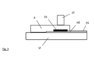
- the FIG. 2 shows a corresponding section through the plastic bumper SF, the heating layer HZ and this covering cover layer DS.
- FIG. 3 shows an embodiment for contacting the plug-in connections of the electrodes EK with a control electronics, not shown.
- a plug SK the outer socket surrounding the plug pins, is mounted on a frame element R.
- the frame R, the frame element engages over the electrodes EK and also parts of the film DS protected by the heating layer HZ.
- the frame element is connected to the body part SF, for example, glued and can in addition to the plug SK also hold the sensor or recording elements (snap-in connections, clips) have for the sensor.
- FIG. 4 a further contacting option is shown.
- the plug SK whose pins are mounted directly on the electrode EK, electrically connected to these.
- the electrodes EK, the corresponding conductor tracks are covered in the edge region by the heating layer HZ and the film DS protecting this heating layer HZ.
- the plug pins of the plug SK are guided in the edge region shown by the heating and the cover layer HZ, DS - these have corresponding openings, passages whose application is recessed in this area.
- the edge of the heating layer HZ is associated with a surface of the heating element at least partially surrounding frame member R, which prevents lateral penetration of dirt or moisture.
- the frame element R is connected to the body part SF, for example. Glued to this. Also in this embodiment, the frame member R receiving, fastening elements for the sensor.
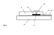
- FIG. 5 shows an embodiment of the contact, in which a crimping, embossing a seated on the top of the frame R contact surface KF with the underlying electrode EK takes place.
- the frame R at least partially surrounds the surface of the heating layer HZ and also covers the electrode EK resting on the heating layer.
- the connected to the body part SF frame R thus forms a lateral termination of the heating surface HZ for the sensor, not shown.
- the contact surface KF which is electrically conductive on the upper side of the frame R, is crimped in a region in such a way that a bridge B passing through the frame body is formed, which connects the contact surface KF electrically to the underlying electrode EK.
- the contact surface KF attached to the frame R has tooth-shaped elements on the side facing the body part, which engage in the heating layer or the electrodes when the frame R is attached, and are thus pressed into contact.
- the teeth are then like those in FIG. 5 formed bridges B formed.
Abstract
Description
Die Erfindung betrifft ein Karosserieteil für ein Kraftfahrzeug nach der Art von Anspruch 1.The invention relates to a body part for a motor vehicle according to the type of claim 1.
Bei Kraftfahrzeugen werden in Karosserieteilen Sensoren verbaut, welche bspw. der Abstandsmessung dienen. Solche Sensoren können in einem Stoßfänger der Vorder- und/oder der Rückseite eingebaut sein und während des Einparkens den Abstand zu einem Hindernis, einem weiteren Fahrzeug erfassen. Derartige Systeme sind als PDC Sensoren bekannt.In motor vehicles sensors are installed in body parts, which serve, for example, the distance measurement. Such sensors may be installed in a front and / or rear bumper and, during parking, detect the distance to an obstacle, another vehicle. Such systems are known as PDC sensors.
Bekannte Sensoren dieser Art sind in Durchbrüchen von Stoßfängern eingelassen und mit einer der Farbe des Fahrzeuges, des Stoßfängers lackiert. Ein Beispiel für einen in einem Karosserieteil, einer Stoßleiste oder einem Stoßfänger eingelassenen PDC Sensor zeigt die
Bei mit Radarwellen arbeitenden Sensoren sind Vorkehrungen zur Vermeidung von Vereisung im Winter zu treffen. Es muss sichergestellt sein, dass sich keine Eisschicht vor dem Abstrahlbereich des Sensors bilden kann, da sonst die Funktion des Sensors nicht mehr gegeben ist. Dazu ist es bekannt, die Sensorfläche mit einer Heizeinrichtung zu versehen. Die
Die vorbekannte Lösung versieht das sende- und empfangsaktive Ende des Sensors mit einer Heizeinrichtung. Der Sensor ist in einer Öffnung des Karosserieteils, des Stoßfängers aufgenommen und somit von außen sichtbar.The prior art solution provides the transmit and receive active end of the sensor with a heater. The sensor is received in an opening of the body part, the bumper and thus visible from the outside.
Nachteilig bei einer derartigen Lösung ist die Sichtbarkeit der Sensoren, auch wenn deren sichtbare Oberfläche in Farbe der Stoßleiste lackiert ist.The disadvantage of such a solution is the visibility of the sensors, even if their visible surface is painted in color of the bumper.
Die Aufgabe der vorliegenden Erfindung besteht darin, ein Karosserieteil für eine Sensoraufnahme in gegenüber den bekannten Ausführungen verbesserter Ausführung zu schaffen.The object of the present invention is to provide a body part for a sensor receptacle in relation to the known versions of improved design.
Diese Aufgabe wird gelöst durch die Merkmale von Anspruch 1. Weiterbildungen ergeben sich aus den Unteransprüchen.This object is achieved by the features of claim 1. Further developments will become apparent from the dependent claims.
Die Erfindung schlägt ein Karosserieteil für ein Kraftfahrzeug vor, insbesondere in Form eines Stoßfängers oder einer Stoßleiste, wobei das Karosserieteil aus einem Kunststoff gefertigt ist und auf seiner Rückseite eine Fläche für einen rückseitig anbringbaren Sensor, vorzugsweise einen Radarsensor aufweist, wobei dieser Fläche eine Heizeinrichtung in Form einer elektrisch leitfähigen Schicht zugeordnet ist.The invention proposes a body part for a motor vehicle, in particular in the form of a bumper or a bumper, wherein the body part is made of a plastic and has on its back a surface for a rear attachable sensor, preferably a radar sensor, said surface is a heater in Form associated with an electrically conductive layer.
Der zu beheizende Bereich in einem Kunststoffbauteil wird mit zwei gegenüberliegenden Elektroden und einem zwischen den Elektroden liegenden Widerstandsheizelement realisiert (Flächenheizelement). Das Widerstandsheizelement, die Heizschicht besteht aus einer viskosen (gieß-, druck-, streichbar) reaktiven Flüssigkeit, welche thermisch oder mit UV Einwirkung in kurzer Zeit aushärtet. Die erfindungsgemäß realisierte Heizeinrichtung - der flächige Auftrag, die flächig gestaltete Schicht, welche in der Schichtdicke und über die Fläche von Strom durchflossen wird - hat gegenüber einer auf einer Folie oder direkt applizierten Heizdrahtgestaltung den Vorteil einer wesentlich unempfindlicheren Gestaltung und gleichzeitig sehr flächigen Heizwirkung. Die leitfähige Schicht der erfindungsgemäßen Heizeinrichtung kann als eine durchgehende Fläche, aber auch in schmalen, zueinander isolierten Streifen aufgebracht sein.The area to be heated in a plastic component is realized with two opposing electrodes and a resistance heating element located between the electrodes (surface heating element). The resistance heating element, the heating layer consists of a viscous (pourable, pressure, spreadable) reactive liquid which cures in a short time either thermally or with UV action. The heating device realized in accordance with the invention - the flat application, the flat layer which is flowed through in the layer thickness and over the surface of current - has the advantage of a much less sensitive design and at the same time a very flat heating effect compared with a heating foil design applied directly to a film or directly. The conductive layer of the heating device according to the invention can be applied as a continuous surface, but also in narrow, mutually insulated strips.
Bevorzugt ist die elektrisch leitfähige Schicht als ein leitfähige Partikel aufweisender, aus solchen Partikeln bestehender Lack, eine viskose Paste gebildet. Der Widerstandswert der Schicht kann durch Beimischungen von Kohlenstoff in Form von Nano-Tubes gezielt bestimmt, eingestellt werden. Die Schicht wird vorzugsweise aufgestrichen oder mittels Siebdruck appliziert.Preferably, the electrically conductive layer is formed as a conductive particles having, consisting of such particles paint, a viscous paste. The resistance of the layer can be determined by additions of carbon in the form of nano-tubes specifically set. The layer is preferably spread or applied by screen printing.
Eine bevorzugte Weiterbildung der Erfindung sieht eine Schutzschicht oberhalb der Heizschicht, diese also vollständig bedeckend, vor. Dadurch werden die Heizschicht schädigende Einflüsse, insbesondere durch Salz, vermieden.A preferred development of the invention provides a protective layer above the heating layer, thus completely covering it. This will make the heating layer damaging influences, in particular by salt avoided.
Die Beschichtung kann direkt auf dem Kunststoffbauteil, der Rückseite des Kunststoffstoßfängers aufgebracht werden.The coating can be applied directly to the plastic component, the back of the plastic bumper.
Des Weiteren kann die Beschichtung, die Heizschicht auch auf eine Folie oder zwischen zwei Folien aufgetragen werden. Die Folie(n) wirken dann als Versiegelungsschicht.Furthermore, the coating, the heating layer can also be applied to a film or between two films. The film (s) then act as a sealing layer.
Die Bestromung der Heizschicht erfolgt über zwei linear ausgebildete Elektroden, welche die Fläche der Heizschicht sich gegenüberliegend umrahmen. Der Anschluss der Elektrodendrähte erfolgt über ein Stecksystem, welches in Form von Steckkontakten gestaltet ist und einem automobilen Standard entspricht. Ein separates elektronisches Bauteil besorgt die Steuerung der Stromstärke, insbesondere in Abhängigkeit des Fahrzustandes und/oder der Temperatur.The energization of the heating layer via two linear electrodes formed which frame the surface of the heating layer opposite each other. The connection of the electrode wires is via a plug-in system, which is designed in the form of plug contacts and corresponds to an automotive standard. A separate electronic component provides the control of the current intensity, in particular depending on the driving condition and / or the temperature.
Die Kontaktierung der Elektroden kann über einen auf der Rückseite des zu beheizenden Bauteils befestigten Rahmen mit integrierten / eingegossenen Stecker realisiert werden. Auch kann die Kontaktierung durch Vercrimpen oder Verprägen der Elektrode mit elektrischen Leitungen erfolgen. Alternativ kann die Kontaktierung zwischen Rahmen und Elektroden durch im Rahmen integrierte, leitfähige Zähne realisiert werden, welche sich durch Anpressen des Rahmens auf die Elektroden in die Elektrodenbahn hineindrücken.The contacting of the electrodes can be realized via a mounted on the back of the component to be heated frame with integrated / cast-in connector. The contacting can be done by crimping or embossing the electrode with electrical lines. Alternatively, the contact between frame and electrodes can be realized by integrated, conductive teeth in the frame, which press into the electrode path by pressing the frame onto the electrodes.
Die Steckverbindungssysteme - die Steckerstifte z.B. - können direkt in oder auf dem aufzuheizenden Bauteil, den Elektroden bzw. der Heizschicht angebracht sein. Auch ist es möglich die Steckerstifte, die Kontaktierelemente an einem Rahmen zu fixieren, der eine Verbindung mit dem Karosseriebauelement aufweist.The connector systems - the plug pins e.g. - Can be mounted directly in or on the component to be heated, the electrodes or the heating layer. It is also possible to fix the connector pins, the contacting elements on a frame which has a connection with the bodywork component.
Vorzugsweise ist die Schicht der Heizeinrichtung in einer Vertiefung des Kunststoffbauteils eingelassen. Die Schichtdicke des Bauteils ist hierbei derartig reduziert, dass sich die gewünschte Strahlungscharakteristik ergibt, die erforderliche Sende- und Empfangsstrahlungsstärke erzielt wird, die erforderliche Abtaugeschwindigkeit erreicht wird. Auch die Schichtdicke der Heizschicht ist derartig gewählt, dass sich einerseits die erforderliche Heizleistung ergibt, andererseits keine Einschränkung der Sensorfunktion erfolgt.Preferably, the layer of the heater is embedded in a recess of the plastic component. The layer thickness of the component is in this case reduced such that the desired radiation characteristic results, the required transmission and receiving radiation intensity is achieved, the required Abtaugeschwindigkeit is achieved. The layer thickness of the heating layer is chosen such that on the one hand the required heating power results, on the other hand no Restriction of the sensor function is done.
Die elektrisch leitfähige Schicht der Heizeinrichtung kann auch dadurch realisiert sein, indem der Kunststoff im vorgesehenen Bereich durch Hinzufügung von leitfähigen Partikeln, bspw. Kohlenstoff Nano-Tubes, elektrisch leitfähig gemacht wird.The electrically conductive layer of the heating device can also be realized by rendering the plastic electrically conductive in the intended area by adding conductive particles, for example carbon nanotubes.
Eine Weiterbildung der Erfindung sieht vor, dass die Rückseite des Karosserieteils in genau dem Flächenbereich ausgedünnt ist, welcher der Kopffläche des Sensors entspricht.A development of the invention provides that the rear side of the body part is thinned in exactly the surface area which corresponds to the top surface of the sensor.
Eine Ausbildung der Erfindung sieht vor, dass der Sensor mittels einer Halterung rückseitig an dem Karosserieteil, dem Stoßfänger angebracht wird.An embodiment of the invention provides that the sensor is attached by means of a holder on the back of the body part, the bumper.
Das Karosserieteil, der Stoßfänger kann rückseitig Rastelemente bzw. Befestigungselemente aufweisen, über welche der Sensor nebst einer ihn aufnehmenden Halterung anbringbar ist.The body part, the bumper may have rear locking elements or fastening elements, via which the sensor together with a holder receiving it is attachable.
Des Weiteren erfolgt die Erläuterung eines Ausführungsbeispiels der Erfindung an Hand der Zeichnungen.Furthermore, the explanation of an embodiment of the invention with reference to the drawings.
Die
Die Spannungsbeaufschlagung der Elektroden EK erfolgt über ein als Stecksystem realisiertes Kontaktsystem SK. Beispielsweise handelt es sich um zwei Steckstifte, je einer an einer der Elektrodenbahnen EK, auf die ein entsprechendes Bucksenteil aufsteckbar ist. Das Buchsenteil steht mit einer Elektronik in Verbindung, über die die Spannungsbeaufschlagung der Heizschicht HZ erfolgt.The voltage application of the electrodes EK via a realized as a plug-in contact system SK. By way of example, these are two plug-in pins, one each on one of the electrode tracks EK, onto which a corresponding piece of the bumper can be plugged. The socket communicates with electronics via which the voltage is applied to the heating layer HZ.
Die Heizschicht HZ ist mit einer als Schutzschicht fungierenden Deckschicht DS überzogen, welche das Material der Heizschicht HZ vor Umwelteinflüssen (Staub, Wasser, Salz) schützt. Die
In
Dem Rand der Heizschicht HZ ist ein die Fläche des Heizelementes wenigstens teilweise umgebendes Rahmenelement R zugeordnet, der ein seitliches Eindringen von Schmutz oder Feuchtigkeit verhindert. Das Rahmenelement R ist mit dem Karosserieteil SF verbunden, bspw. mit diesem verklebt. Auch bei dieser Ausgestaltung kann das Rahmenelement R Aufnahme-, Befestigungselemente für den Sensor aufweisen.The edge of the heating layer HZ is associated with a surface of the heating element at least partially surrounding frame member R, which prevents lateral penetration of dirt or moisture. The frame element R is connected to the body part SF, for example. Glued to this. Also in this embodiment, the frame member R receiving, fastening elements for the sensor.
Die auf der Oberseite des Rahmens R elektrisch leitfähige Kontaktfläche KF ist in einem Bereich derartig vercrimpt, verprägt, so dass sich eine durch den Rahmenkörper hindurchgreifende Brücke B bildet, welche die Kontaktfläche KF elektrisch mit der darunter liegenden Elektrode EK verbindet.The contact surface KF, which is electrically conductive on the upper side of the frame R, is crimped in a region in such a way that a bridge B passing through the frame body is formed, which connects the contact surface KF electrically to the underlying electrode EK.
Letztlich kann auch vorgesehen sein, dass die am Rahmen R angebrachte Kontaktfläche KF an der zum Karosserieteil weisenden Seite zahnförmige Elemente aufweist, welche beim Anbringen des Rahmens R in die Heizschicht bzw. die Elektroden greifen, eingedrückt werden und so die Kontaktierung bewirken. Die Zähne sind dann wie die in
- SFSF
- Karosserieteil, Stoßfänger, KunststoffstoßfängerBody part, bumper, plastic bumper
- HZHZ
- Heizschicht, elektrisch leitende Schicht, HeizeinrichtungHeating layer, electrically conductive layer, heating device
- DSDS
- Deckschicht, Schutzschicht, FolieCovering layer, protective layer, foil
- EKEK
- Elektrode, LeiterbahnElectrode, trace
- SKSK
- Steckkontakt, KontaktierungPlug contact, contacting
- RR
- Rahmenframe
- KFKF
- Kontaktflächecontact area
- BB
- Brücke, leitende VerbindungBridge, conducting connection
Claims (16)
die elektrisch leitfähige Schicht (HZ) besteht aus einer elektrisch leitfähige Partikel aufweisenden, flüssig bzw. pastös verarbeitbaren Substanz, welche flächig aufgebracht wird.Bodywork part according to claim 1,
the electrically conductive layer (HZ) consists of an electrically conductive particles having, liquid or pasty processable substance which is applied flat.
die elektrisch leitfähige Schicht (HZ) besteht aus einem Kunststoff, der durch Hinzufügung von elektrisch leitfähigen Partikeln in der vorgesehenen Fläche elektrisch leitfähig gemacht wurde.Bodywork part according to claim 1,
the electrically conductive layer (HZ) consists of a plastic that has been made electrically conductive by adding electrically conductive particles in the intended area.
die elektrisch leitfähige Schicht (HZ) weist Elektroden (EK) auf, über welche die Schicht (HZ) mit Spannung beaufschlagbar ist.Bodywork part according to one of the preceding claims,
the electrically conductive layer (HZ) has electrodes (EK) via which the layer (HZ) can be subjected to voltage.
die Elektroden (EK) weisen ein Stecksystem (SK) zur Kontaktierung mit einer die Spannungsbeaufschlagung bewirkenden Elektronik auf.Bodywork part according to claim 4,
the electrodes (EK) have a plug-in system (SK) for making contact with a voltage-causing electronics.
die elektrisch leitfähige Schicht (HZ) ist mit einer sie bedeckenden Deckschicht (DS) überzogen.Bodywork part according to one of the preceding claims,
the electrically conductive layer (HZ) is covered with a covering layer (DS) covering it.
die elektrisch leitfähige Schicht (HZ) ist direkt auf einer Fläche des Karosserieteils (SF) aufgebracht.Bodywork part according to one of the preceding claims,
the electrically conductive layer (HZ) is applied directly to a surface of the body part (SF).
die elektrisch leitfähige Schicht (HZ) ist auf einer Folie aufgebracht, welche auf eine Fläche des Karosserieteils (SF) aufbringbar ist.Bodywork part according to one of the preceding claims,
the electrically conductive layer (HZ) is applied to a foil which can be applied to a surface of the body part (SF).
die elektrisch leitfähige Schicht (HZ) ist in einem Flächenbereich des Karosserieteils aufgebracht, der eine reduzierte Schichtdicke aufweist.Bodywork part according to one of the preceding claims,
the electrically conductive layer (HZ) is applied in a surface region of the body part which has a reduced layer thickness.
die Deckschicht (DS) ist als eine Folie ausgebildet.Bodywork part according to claim 6,
the cover layer (DS) is formed as a film.
die Heizschicht (HZ) ist mit einer ihre Rückseite als Schutzschicht bedeckenden Folie (DS) versehen und weist auf ihrer vorderen, dem Karosserieteil (SF) zugewandten Seite eine Klebschicht auf.Bodywork part according to one of the preceding claims,
the heating layer (HZ) is provided with a foil (DS) covering its rear side as a protective layer and has an adhesive layer on its front side facing the body part (SF).
die Fläche der Heizschicht (HZ) ist wenigstens teilweise von einem Rahmen (R) umgeben, der innenseitig mit der Karosserieteil (F) verbunden ist.Bodywork part according to one of the preceding claims,
the surface of the heating layer (HZ) is at least partially surrounded by a frame (R), which is internally connected to the body part (F).
die elektrische Kontaktierung der Heizschicht (HZ) erfolgt über am Rahmen (R) angebrachte Elemente, vorzugsweise einen Steckverbinder (SK).Body part at least according to claim 12,
the electrical contacting of the heating layer (HZ) via the frame (R) attached elements, preferably a connector (SK).
die elektrische Kontaktierung der Elektroden (EK) der Heizeinrichtung (HZ) erfolgt durch einen am Rahmen (R) angebrachten Steckverbinder (SK).Body part at least according to claim 4 and 12,
the electrical contacting of the electrodes (EK) of the heating device (HZ) is effected by a connector (SK) attached to the frame (R).
die elektrische Kontaktierung der Heizschicht (HZ) erfolgt über eine am Rahmen (R) angebrachte metallische Kontaktfläche (KF), welche über eine durch Verprägung, Vercrimpung gebildete Brücke (B) eine elektrische Verbindung zu der Heizeinrichtung (HZ), vorzugsweise den Elektroden (EK) der Heizeinrichtung (HZ) bildet.Body part at least according to claim 12,
the electrical contacting of the heating layer (HZ) via a on the frame (R) mounted metallic contact surface (KF), which via an embossing, crimping bridge (B) an electrical connection to the heater (HZ), preferably the electrodes (EK ) of the heater (HZ) forms.
der Rahmen (R) überdeckt wenigstens in einem Randbereich die Heizschicht (HZ) und vorzugsweise auch eine die Heizschicht (HZ) schützende Deckschicht (DS).Body part at least according to claim 4,
the frame (R) covers at least in an edge region the heating layer (HZ) and preferably also a covering layer (DS) protecting the heating layer (HZ).
Applications Claiming Priority (2)
| Application Number | Priority Date | Filing Date | Title |
|---|---|---|---|
| DE102012222557 | 2012-12-07 | ||
| DE102013200364.1A DE102013200364A1 (en) | 2012-12-07 | 2013-01-14 | body part |
Publications (2)
| Publication Number | Publication Date |
|---|---|
| EP2741105A2 true EP2741105A2 (en) | 2014-06-11 |
| EP2741105A3 EP2741105A3 (en) | 2014-08-13 |
Family
ID=49641521
Family Applications (1)
| Application Number | Title | Priority Date | Filing Date |
|---|---|---|---|
| EP13193168.5A Withdrawn EP2741105A3 (en) | 2012-12-07 | 2013-11-15 | Vehicle body part |
Country Status (2)
| Country | Link |
|---|---|
| EP (1) | EP2741105A3 (en) |
| DE (1) | DE102013200364A1 (en) |
Cited By (6)
| Publication number | Priority date | Publication date | Assignee | Title |
|---|---|---|---|---|
| WO2017042284A1 (en) * | 2015-09-11 | 2017-03-16 | Commissariat A L'energie Atomique Et Aux Energies Alternatives | Radome provided with a resistive heating system formed from strips of metal nanoelements |
| FR3041104A1 (en) * | 2015-09-14 | 2017-03-17 | Plastic Omnium Cie | HEATING DEVICE FOR PROTECTING A MOTOR VEHICLE RADAR |
| WO2017055153A1 (en) * | 2015-09-30 | 2017-04-06 | Hella Kgaa Hueck & Co. | Method for producing a radome and corresponding radome |
| WO2020099670A1 (en) * | 2018-11-16 | 2020-05-22 | Compagnie Plastic Omnium | Multi-layer motor vehicle exterior part comprising a heating element |
| EP3772133A1 (en) * | 2019-07-29 | 2021-02-03 | Compagnie Plastic Omnium SE | Protection device for lidar of a motor vehicle |
| CN112690040A (en) * | 2018-09-21 | 2021-04-20 | 纬湃科技有限责任公司 | Contact device and arrangement having a substrate and a contact device arranged thereon |
Families Citing this family (1)
| Publication number | Priority date | Publication date | Assignee | Title |
|---|---|---|---|---|
| DE102018206290B3 (en) | 2018-04-24 | 2019-06-19 | Audi Ag | Radar sensor device for a motor vehicle and motor vehicle |
Citations (2)
| Publication number | Priority date | Publication date | Assignee | Title |
|---|---|---|---|---|
| DE10314862A1 (en) | 2003-04-02 | 2004-10-14 | Bayerische Motoren Werke Ag | Parking aid sensor arrangement |
| DE102011107216A1 (en) | 2011-07-13 | 2012-03-08 | Daimler Ag | Radome for protecting transmission-and receiving device in driver assisting system against e.g. snow to transmit and receive radar wave in motor vehicle to recognize object, has heating device arranged between supporter and layer |
Family Cites Families (3)
| Publication number | Priority date | Publication date | Assignee | Title |
|---|---|---|---|---|
| DE10149337A1 (en) * | 2001-10-06 | 2003-04-17 | Bosch Gmbh Robert | Device for a front cover unit of a motor vehicle removes solid or liquid material and/or prevents their adhesion to a given zone of the front cover unit |
| DE10156699B4 (en) * | 2001-11-17 | 2005-06-09 | Audi Ag | Method of making a heatable radome badge and radome badge |
| DE102004049148A1 (en) * | 2004-10-07 | 2006-04-13 | Rehau Ag + Co | Heating element on a polymeric inner surface of a front module / bumper of a motor vehicle in operative connection with a Radarsende- and - receiving unit |
-
2013
- 2013-01-14 DE DE102013200364.1A patent/DE102013200364A1/en not_active Withdrawn
- 2013-11-15 EP EP13193168.5A patent/EP2741105A3/en not_active Withdrawn
Patent Citations (2)
| Publication number | Priority date | Publication date | Assignee | Title |
|---|---|---|---|---|
| DE10314862A1 (en) | 2003-04-02 | 2004-10-14 | Bayerische Motoren Werke Ag | Parking aid sensor arrangement |
| DE102011107216A1 (en) | 2011-07-13 | 2012-03-08 | Daimler Ag | Radome for protecting transmission-and receiving device in driver assisting system against e.g. snow to transmit and receive radar wave in motor vehicle to recognize object, has heating device arranged between supporter and layer |
Cited By (11)
| Publication number | Priority date | Publication date | Assignee | Title |
|---|---|---|---|---|
| WO2017042284A1 (en) * | 2015-09-11 | 2017-03-16 | Commissariat A L'energie Atomique Et Aux Energies Alternatives | Radome provided with a resistive heating system formed from strips of metal nanoelements |
| FR3041166A1 (en) * | 2015-09-11 | 2017-03-17 | Commissariat Energie Atomique | RADOME EQUIPPED WITH A HEATING RESISTIVE SYSTEM STRUCTURE IN BANDS OF METAL NANO-ELEMENTS |
| FR3041104A1 (en) * | 2015-09-14 | 2017-03-17 | Plastic Omnium Cie | HEATING DEVICE FOR PROTECTING A MOTOR VEHICLE RADAR |
| WO2017055153A1 (en) * | 2015-09-30 | 2017-04-06 | Hella Kgaa Hueck & Co. | Method for producing a radome and corresponding radome |
| US11005172B2 (en) | 2015-09-30 | 2021-05-11 | HELLA GmbH & Co. KGaA | Method for producing a radome and corresponding radome |
| CN112690040A (en) * | 2018-09-21 | 2021-04-20 | 纬湃科技有限责任公司 | Contact device and arrangement having a substrate and a contact device arranged thereon |
| WO2020099670A1 (en) * | 2018-11-16 | 2020-05-22 | Compagnie Plastic Omnium | Multi-layer motor vehicle exterior part comprising a heating element |
| FR3088600A1 (en) * | 2018-11-16 | 2020-05-22 | Compagnie Plastic Omnium | OUTSIDE PART OF A MULTI-LAYER MOTOR VEHICLE COMPRISING A HEATING ELEMENT |
| CN113015659A (en) * | 2018-11-16 | 2021-06-22 | 全耐塑料公司 | Multi-layer motor vehicle exterior component comprising a heating element |
| EP3772133A1 (en) * | 2019-07-29 | 2021-02-03 | Compagnie Plastic Omnium SE | Protection device for lidar of a motor vehicle |
| FR3099436A1 (en) * | 2019-07-29 | 2021-02-05 | Compagnie Plastic Omnium Se | Motor Vehicle Lidar Protection Device |
Also Published As
| Publication number | Publication date |
|---|---|
| EP2741105A3 (en) | 2014-08-13 |
| DE102013200364A1 (en) | 2014-06-12 |
Similar Documents
| Publication | Publication Date | Title |
|---|---|---|
| EP2741105A2 (en) | Vehicle body part | |
| WO2017055153A1 (en) | Method for producing a radome and corresponding radome | |
| EP1966011A2 (en) | Capacitive rain sensor | |
| EP1006766B1 (en) | Electronic device | |
| WO2017055182A1 (en) | Method for producing a radome and corresponding radome | |
| WO2009043641A1 (en) | Contacting arrangement and contacting method for conductive tracks of heating systems and antennas in motor vehicle window panes | |
| DE4235063A1 (en) | Car glass made of laminated glass with wires embedded in the intermediate layer and a connection cable | |
| WO2012092632A1 (en) | Medical electrode with printed shielded feed line | |
| EP3815462B1 (en) | Pane with electric connection element and connecting cable | |
| WO2012065893A1 (en) | Contact-making arrangement for conductors provided on flat structures, namely panes of glass | |
| DE102013207482A1 (en) | Heatable surface element | |
| EP2614589B1 (en) | Capacitive distance sensor | |
| DE102016225668A1 (en) | Plastic component with sensor | |
| EP2947773A1 (en) | Variably insertable sensor unit | |
| EP1649725A1 (en) | Method for electrically insulating an electrical functional element and device with functional elements, insulated in such a way | |
| DE102019211845A1 (en) | Heatable body elements | |
| EP3941741A1 (en) | Composite pane comprising a functional inlay element | |
| WO2019016344A1 (en) | Sensor unit | |
| DE102019006393A1 (en) | Device for heating a surface, in particular a cover plate, for a vehicle and a vehicle | |
| EP4110579A1 (en) | Heatable plastics component and method for producing same | |
| DE102019130095A1 (en) | Cover for an electromagnetic sensor with heating structure | |
| DE102016218177A1 (en) | Mounting method for a sensor module and sensor module | |
| DE102004022169B4 (en) | Connecting device for an electrically assisted steering system | |
| WO2023248113A1 (en) | Protective cover for sensors relating to automotive engineering, and production method for a protective cover | |
| WO2019115069A1 (en) | Heating device |
Legal Events
| Date | Code | Title | Description |
|---|---|---|---|
| PUAI | Public reference made under article 153(3) epc to a published international application that has entered the european phase |
Free format text: ORIGINAL CODE: 0009012 |
|
| 17P | Request for examination filed |
Effective date: 20131115 |
|
| AK | Designated contracting states |
Kind code of ref document: A2 Designated state(s): AL AT BE BG CH CY CZ DE DK EE ES FI FR GB GR HR HU IE IS IT LI LT LU LV MC MK MT NL NO PL PT RO RS SE SI SK SM TR |
|
| AX | Request for extension of the european patent |
Extension state: BA ME |
|
| PUAL | Search report despatched |
Free format text: ORIGINAL CODE: 0009013 |
|
| AK | Designated contracting states |
Kind code of ref document: A3 Designated state(s): AL AT BE BG CH CY CZ DE DK EE ES FI FR GB GR HR HU IE IS IT LI LT LU LV MC MK MT NL NO PL PT RO RS SE SI SK SM TR |
|
| AX | Request for extension of the european patent |
Extension state: BA ME |
|
| RIC1 | Information provided on ipc code assigned before grant |
Ipc: G01S 13/93 20060101AFI20140708BHEP |
|
| R17P | Request for examination filed (corrected) |
Effective date: 20140723 |
|
| RBV | Designated contracting states (corrected) |
Designated state(s): AL AT BE BG CH CY CZ DE DK EE ES FI FR GB GR HR HU IE IS IT LI LT LU LV MC MK MT NL NO PL PT RO RS SE SI SK SM TR |
|
| 17Q | First examination report despatched |
Effective date: 20161212 |
|
| RAP1 | Party data changed (applicant data changed or rights of an application transferred) |
Owner name: MAGNA EXTERIORS (GERMANY) GMBH |
|
| STAA | Information on the status of an ep patent application or granted ep patent |
Free format text: STATUS: THE APPLICATION HAS BEEN WITHDRAWN |
|
| 18W | Application withdrawn |
Effective date: 20190313 |