EP2741039A1 - Graphite crucible - Google Patents
Graphite crucible Download PDFInfo
- Publication number
- EP2741039A1 EP2741039A1 EP12822079.5A EP12822079A EP2741039A1 EP 2741039 A1 EP2741039 A1 EP 2741039A1 EP 12822079 A EP12822079 A EP 12822079A EP 2741039 A1 EP2741039 A1 EP 2741039A1
- Authority
- EP
- European Patent Office
- Prior art keywords
- graphite crucible
- graphite
- treated
- crucible
- gas discharge
- Prior art date
- Legal status (The legal status is an assumption and is not a legal conclusion. Google has not performed a legal analysis and makes no representation as to the accuracy of the status listed.)
- Withdrawn
Links
- OKTJSMMVPCPJKN-UHFFFAOYSA-N Carbon Chemical compound [C] OKTJSMMVPCPJKN-UHFFFAOYSA-N 0.000 title claims abstract description 209
- 229910002804 graphite Inorganic materials 0.000 title claims abstract description 193
- 239000010439 graphite Substances 0.000 title claims abstract description 193
- XEEYBQQBJWHFJM-UHFFFAOYSA-N Iron Chemical compound [Fe] XEEYBQQBJWHFJM-UHFFFAOYSA-N 0.000 claims description 64
- 238000002844 melting Methods 0.000 claims description 36
- 230000008018 melting Effects 0.000 claims description 36
- 229910052742 iron Inorganic materials 0.000 claims description 31
- 239000012535 impurity Substances 0.000 claims description 19
- PXHVJJICTQNCMI-UHFFFAOYSA-N Nickel Chemical compound [Ni] PXHVJJICTQNCMI-UHFFFAOYSA-N 0.000 claims description 14
- 229910052759 nickel Inorganic materials 0.000 claims description 7
- 239000000203 mixture Substances 0.000 claims description 6
- RTAQQCXQSZGOHL-UHFFFAOYSA-N Titanium Chemical compound [Ti] RTAQQCXQSZGOHL-UHFFFAOYSA-N 0.000 claims description 5
- 239000010936 titanium Substances 0.000 claims description 5
- 229910052719 titanium Inorganic materials 0.000 claims description 5
- 238000004519 manufacturing process Methods 0.000 claims description 2
- 229920001296 polysiloxane Polymers 0.000 claims description 2
- 239000011148 porous material Substances 0.000 abstract description 9
- 238000002309 gasification Methods 0.000 abstract description 5
- 239000007789 gas Substances 0.000 description 69
- 238000010438 heat treatment Methods 0.000 description 17
- 229910052799 carbon Inorganic materials 0.000 description 16
- XUIMIQQOPSSXEZ-UHFFFAOYSA-N Silicon Chemical compound [Si] XUIMIQQOPSSXEZ-UHFFFAOYSA-N 0.000 description 12
- 229910052710 silicon Inorganic materials 0.000 description 12
- 239000010703 silicon Substances 0.000 description 12
- CPLXHLVBOLITMK-UHFFFAOYSA-N Magnesium oxide Chemical compound [Mg]=O CPLXHLVBOLITMK-UHFFFAOYSA-N 0.000 description 11
- 238000010828 elution Methods 0.000 description 8
- 239000000463 material Substances 0.000 description 8
- 229910052751 metal Inorganic materials 0.000 description 8
- 239000002184 metal Substances 0.000 description 7
- 238000001816 cooling Methods 0.000 description 6
- 230000003628 erosive effect Effects 0.000 description 6
- 239000000395 magnesium oxide Substances 0.000 description 6
- 238000010587 phase diagram Methods 0.000 description 6
- 229910010271 silicon carbide Inorganic materials 0.000 description 6
- 239000002893 slag Substances 0.000 description 6
- 238000006243 chemical reaction Methods 0.000 description 5
- 230000000052 comparative effect Effects 0.000 description 5
- 239000000919 ceramic Substances 0.000 description 4
- 239000000155 melt Substances 0.000 description 4
- 229910001018 Cast iron Inorganic materials 0.000 description 3
- 229910017112 Fe—C Inorganic materials 0.000 description 3
- 229910018540 Si C Inorganic materials 0.000 description 3
- 238000011109 contamination Methods 0.000 description 3
- 230000007797 corrosion Effects 0.000 description 3
- 238000005260 corrosion Methods 0.000 description 3
- 230000003292 diminished effect Effects 0.000 description 3
- 230000007246 mechanism Effects 0.000 description 3
- 238000000034 method Methods 0.000 description 3
- 238000000465 moulding Methods 0.000 description 3
- 230000005855 radiation Effects 0.000 description 3
- 230000035939 shock Effects 0.000 description 3
- HBMJWWWQQXIZIP-UHFFFAOYSA-N silicon carbide Chemical compound [Si+]#[C-] HBMJWWWQQXIZIP-UHFFFAOYSA-N 0.000 description 3
- 239000000126 substance Substances 0.000 description 3
- ZAMOUSCENKQFHK-UHFFFAOYSA-N Chlorine atom Chemical compound [Cl] ZAMOUSCENKQFHK-UHFFFAOYSA-N 0.000 description 2
- 229910000640 Fe alloy Inorganic materials 0.000 description 2
- YCKRFDGAMUMZLT-UHFFFAOYSA-N Fluorine atom Chemical compound [F] YCKRFDGAMUMZLT-UHFFFAOYSA-N 0.000 description 2
- MCMNRKCIXSYSNV-UHFFFAOYSA-N Zirconium dioxide Chemical compound O=[Zr]=O MCMNRKCIXSYSNV-UHFFFAOYSA-N 0.000 description 2
- PNEYBMLMFCGWSK-UHFFFAOYSA-N aluminium oxide Inorganic materials [O-2].[O-2].[O-2].[Al+3].[Al+3] PNEYBMLMFCGWSK-UHFFFAOYSA-N 0.000 description 2
- 238000009835 boiling Methods 0.000 description 2
- 239000003575 carbonaceous material Substances 0.000 description 2
- 229910052801 chlorine Inorganic materials 0.000 description 2
- 239000000460 chlorine Substances 0.000 description 2
- 239000004567 concrete Substances 0.000 description 2
- 238000005520 cutting process Methods 0.000 description 2
- 230000005496 eutectics Effects 0.000 description 2
- 229910052731 fluorine Inorganic materials 0.000 description 2
- 239000011737 fluorine Substances 0.000 description 2
- 239000007770 graphite material Substances 0.000 description 2
- 230000006698 induction Effects 0.000 description 2
- 239000010410 layer Substances 0.000 description 2
- 239000012768 molten material Substances 0.000 description 2
- -1 polyvinyl chloride Chemical compound 0.000 description 2
- 230000008569 process Effects 0.000 description 2
- RYGMFSIKBFXOCR-UHFFFAOYSA-N Copper Chemical compound [Cu] RYGMFSIKBFXOCR-UHFFFAOYSA-N 0.000 description 1
- RWSOTUBLDIXVET-UHFFFAOYSA-N Dihydrogen sulfide Chemical compound S RWSOTUBLDIXVET-UHFFFAOYSA-N 0.000 description 1
- 229910001060 Gray iron Inorganic materials 0.000 description 1
- 229910000831 Steel Inorganic materials 0.000 description 1
- LSNNMFCWUKXFEE-UHFFFAOYSA-N Sulfurous acid Chemical class OS(O)=O LSNNMFCWUKXFEE-UHFFFAOYSA-N 0.000 description 1
- ATJFFYVFTNAWJD-UHFFFAOYSA-N Tin Chemical compound [Sn] ATJFFYVFTNAWJD-UHFFFAOYSA-N 0.000 description 1
- 230000009471 action Effects 0.000 description 1
- 229910052782 aluminium Inorganic materials 0.000 description 1
- XAGFODPZIPBFFR-UHFFFAOYSA-N aluminium Chemical compound [Al] XAGFODPZIPBFFR-UHFFFAOYSA-N 0.000 description 1
- 239000012300 argon atmosphere Substances 0.000 description 1
- 238000005266 casting Methods 0.000 description 1
- 239000000571 coke Substances 0.000 description 1
- 229910052802 copper Inorganic materials 0.000 description 1
- 239000010949 copper Substances 0.000 description 1
- 230000003247 decreasing effect Effects 0.000 description 1
- 238000007599 discharging Methods 0.000 description 1
- 230000000694 effects Effects 0.000 description 1
- 150000002366 halogen compounds Chemical class 0.000 description 1
- 229910000037 hydrogen sulfide Inorganic materials 0.000 description 1
- 239000007788 liquid Substances 0.000 description 1
- AXZKOIWUVFPNLO-UHFFFAOYSA-N magnesium;oxygen(2-) Chemical compound [O-2].[Mg+2] AXZKOIWUVFPNLO-UHFFFAOYSA-N 0.000 description 1
- 230000005389 magnetism Effects 0.000 description 1
- 150000001247 metal acetylides Chemical class 0.000 description 1
- 238000005272 metallurgy Methods 0.000 description 1
- 150000002739 metals Chemical class 0.000 description 1
- 230000004048 modification Effects 0.000 description 1
- 238000012986 modification Methods 0.000 description 1
- 239000004570 mortar (masonry) Substances 0.000 description 1
- 229920000620 organic polymer Polymers 0.000 description 1
- 239000002245 particle Substances 0.000 description 1
- 239000012466 permeate Substances 0.000 description 1
- 230000010287 polarization Effects 0.000 description 1
- 229920001343 polytetrafluoroethylene Polymers 0.000 description 1
- 239000004810 polytetrafluoroethylene Substances 0.000 description 1
- 229920000915 polyvinyl chloride Polymers 0.000 description 1
- 239000004800 polyvinyl chloride Substances 0.000 description 1
- 239000002994 raw material Substances 0.000 description 1
- 230000009257 reactivity Effects 0.000 description 1
- 150000003839 salts Chemical class 0.000 description 1
- 229920006395 saturated elastomer Polymers 0.000 description 1
- 239000007787 solid Substances 0.000 description 1
- 229910052596 spinel Inorganic materials 0.000 description 1
- 239000011029 spinel Substances 0.000 description 1
- 239000010935 stainless steel Substances 0.000 description 1
- 229910001220 stainless steel Inorganic materials 0.000 description 1
- 239000010959 steel Substances 0.000 description 1
- 150000003467 sulfuric acid derivatives Chemical class 0.000 description 1
- 239000002344 surface layer Substances 0.000 description 1
- 230000008646 thermal stress Effects 0.000 description 1
- 230000008719 thickening Effects 0.000 description 1
- 239000002699 waste material Substances 0.000 description 1
- 229910052845 zircon Inorganic materials 0.000 description 1
- GFQYVLUOOAAOGM-UHFFFAOYSA-N zirconium(iv) silicate Chemical compound [Zr+4].[O-][Si]([O-])([O-])[O-] GFQYVLUOOAAOGM-UHFFFAOYSA-N 0.000 description 1
Images



Classifications
-
- F—MECHANICAL ENGINEERING; LIGHTING; HEATING; WEAPONS; BLASTING
- F27—FURNACES; KILNS; OVENS; RETORTS
- F27B—FURNACES, KILNS, OVENS OR RETORTS IN GENERAL; OPEN SINTERING OR LIKE APPARATUS
- F27B14/00—Crucible or pot furnaces
- F27B14/08—Details specially adapted for crucible or pot furnaces
- F27B14/10—Crucibles
-
- F—MECHANICAL ENGINEERING; LIGHTING; HEATING; WEAPONS; BLASTING
- F27—FURNACES; KILNS; OVENS; RETORTS
- F27D—DETAILS OR ACCESSORIES OF FURNACES, KILNS, OVENS OR RETORTS, IN SO FAR AS THEY ARE OF KINDS OCCURRING IN MORE THAN ONE KIND OF FURNACE
- F27D1/00—Casings; Linings; Walls; Roofs
- F27D1/0003—Linings or walls
- F27D1/0006—Linings or walls formed from bricks or layers with a particular composition or specific characteristics
Definitions
- the present invention relates to a graphite crucible, and more particularly to a graphite crucible for melting an object to be treated, such as a metal.
- Object substances include, for example, tin (melting point: 232°C), lead (melting point: 328°C), aluminum (melting point: 660°C), copper (melting point: 1083°C), silicon (melting point: 1410°C), iron (melting point: 1539°C), nickel (melting point: 1726°C), and the like.
- tin melting point: 232°C
- lead melting point: 328°C
- aluminum melting point: 660°C
- copper melting point: 1083°C
- silicon melting point: 1410°C
- iron melting point: 1539°C
- nickel nickel
- crucibles for melting an object to be treated such as an iron-based object needs thermal resistance of 1,400°C or higher and corrosion resistance
- crucibles made of oxide-based ceramics such as alumina and magnesia, or graphite-based crucibles in which graphite is added to the oxide-based ceramics.
- oxide-based ceramics for use in these crucibles those having most suitable chemical composition, which exhibit corrosion resistance against various molten metals or slag, are used.
- alumina, magnesia, zirconia, zircon, spinel, and the like are used as aggregates.
- graphite-based crucibles it has been described that thermal shock resistance of crucibles is enhanced by adding graphite that has high heat conductivity and low elastic modulus (Patent Document 1).
- Patent Document 1 JP-A-H11-116336
- An object of the invention is to provide a graphite crucible capable of melting an object to be treated safely without scattering it to form a solidified body.
- the invention provides the following:
- the graphite crucible has a gas discharge part that is opened at the upper end side of the body part, in the case where a corrosive gas or a reactive gas is generated from the object to be treated or by the reaction of the object to be treated with graphite, the corrosive gas or reactive gas passing through the body part of the graphite crucible can be introduced into the gas discharge part. Therefore, it is possible to make the inside of the melting apparatus difficult to be filled with the corrosive gas or reactive gas. As a result, it is thought that corrosion of the melting apparatus can be prevented even when a porous graphite crucible is used.
- Fig. 1 shows a graphite crucible according to the embodiment 1 of the invention.
- Fig. 1(A) is a sectional view along the A-A line in Fig. 1(B) including a central axis of the graphite crucible according to the embodiment 1 of the invention
- Fig. 1(B) is a top plan view of the graphite crucible according to the embodiment 1 of the invention.
- the graphite crucible means that graphite is a substantial constitutional component thereof.
- graphite may be any kind of graphite and may be anisotropic graphite such as an extruded material or an embossed material or an isotropic graphite material obtained by cold isostatic molding (CIP molding: Cold Isostatic Press).
- CIP molding Cold Isostatic Press
- the graphite obtained by the CIP molding has high strength since a fine raw material (e.g., cokes having a particle diameter of 10 to 20 ⁇ m) can be used, and hence, the texture becomes fine.
- pressurization is performed using a liquid pressurization medium, an isotropic material can be obtained. Since there is no directivity in thermal expansion coefficient, distorted deformation hardly occurs, and thus, thermal stress caused by the distorted deformation is hardly generated, so that it is possible to make troubles such as cracks less likely to occur.
- the graphite crucible 1 according to the embodiment 1 of the invention is characterized by including a bottom part 2, a body part 3, and a treatment part 4 having an inlet port 4a, and further including a gas discharge part 5 that is opened at the upper end side of the body part.
- a space excluding the gas discharge part 5 from the space between a crucible inner periphery 1a that defines the space of the treatment part 4 and a crucible outer periphery 1b is made of graphite.
- the bottom part 2 is a part below an inner bottom surface 2a when the crucible is cut out to the crucible outer periphery by the plane including the inner bottom surface 2a that is a lower end part of the crucible inner periphery 1a.
- the inner bottom surface 2a may be a curved surface instead of a planar surface as shown in Fig. 1(A) .
- As the curved surface there may be a curved surface having an extreme point at the lower end of the crucible inner periphery, where the tangent surface of the extreme point coincides with the inner bottom surface 2a.
- the bottom part 2 has an outer bottom surface 2b that corresponds to the lower end surface of the crucible outer periphery 1b.
- the body part 3 is a part between the crucible inner periphery 1a and the crucible outer periphery 1b and is a part other than the bottom part 2 of the graphite crucible 1.
- the gas discharge part 5 is a space (hole) closed at the lower end side and opened at the upper end side of the body part and has a function of discharging a gas
- the shape, size, position of the closed port, the number, and the like thereof are not particularly limited.
- the gas discharge part 5 shown in Fig. 1(A) and Fig. 1(B) is cylindrical and has a closed port 5a at the lower end side and an opened port 5b at the upper end side of the body part, 20 pieces of the gas discharge part 5 are concentrically provided in the body part, and they are provided at such positions that the central angles thereof are mutually separated by almost 18°.
- the position of the closed port 5a is slightly lower than the inner bottom surface 2a.
- the thickness T of the bottom part 2 is preferably thicker than the minimum value of the distance t between the gas discharge part periphery 5c and the crucible inner periphery 1a.
- the distance t between the gas discharge part periphery 5c and the crucible inner periphery 1a since t of each hole falls within a certain range for each of 20 pieces of the gas discharge part, the smallest one among them is taken as the minimum value.
- the minimum value is the smallest one of the distances t between the respective gas discharge part peripheries 5c and the crucible inner periphery 1a.
- the thickness of the bottom part 2 is a distance between the inner bottom surface 2a and the outer bottom surface 2b.
- the thickness is a distance between the above-described tangent surface and the outer bottom surface 2b.
- the relationship between the thickness of the bottom part 2 and the distance t is the same in the case where the gas discharge part shown in the embodiment of Fig. 2 is employed.
- the graphite constituting the graphite crucible 1 Since the graphite constituting the graphite crucible 1 is porous, it has many pores inside. Since it has pores, air bubbles are generated in the course of elution of the graphite into the object to be treated at the time of melting and are diffused into the molten object to be treated. On this occasion, gasification of the impurities contained in the object to be treated is enhanced and the bumping of the object to be treated can be prevented.
- the object to be treated contains an oxide
- it is reduced by the graphite to generate a gas of CO or CO 2 , and similarly the gas of CO or CO 2 is continuously released as air bubbles into the molten object to be treated.
- gasification of the impurities contained in the object to be treated is enhanced, so that it is thought that sudden boiling of the impurities contained in the object to be treated and the bumping can be prevented. Since the bumping can be prevented, it is thought that scattering of the object to be treated into the apparatus and contamination thereof can be prevented.
- the gas discharge part 5 functions as a discharge port of a gas as described above. Since the graphite crucible is made of graphite that is porous, it has a property that a gas easily permeates even to the outside of the graphite crucible. Depending on the component(s) contained in the object to be treated, a gas is generated from the object to be treated itself or by the reaction with the graphite crucible.
- a chlorine-based gas is generated.
- a fluorine-based gas is generated.
- the object to be treated contains a sulfate salt or a sulfite salt, it reacts with graphite to generate a corrosive gas such as hydrogen sulfide.
- the graphite crucible 1 Since the graphite crucible 1 has the gas discharge part 5, a gas generated by the reaction with the crucible can be discharged to the upper part of the crucible through the gas discharge part 5 of the body part 3.
- the gas discharged as such can be rapidly discharged from the melting apparatus by appropriately providing a discharge port of the melting apparatus on the graphite crucible.
- the thickness T of the body part 2 is preferably thicker than the minimum value of the distance t between the gas discharge part periphery 5c and the crucible inner periphery 1 a. The reason will be described below.
- the object to be treated When a solid (clumpy or powdery) object to be treated is placed in the graphite crucible 1 and melted, the object to be treated is reduced in volume in the process thereof and is likely to gather on the bottom of the graphite crucible.
- the object to be treated in order to efficiently use the graphite crucible, the object to be treated is added repeatedly until the object to be treated is sufficiently filled in the treatment part 4 of the graphite crucible. Therefore, the bottom part 2 of the graphite crucible is in contact with the object to be treated for a longer period of time.
- the graphite constituting the graphite crucible becomes easily eluted into the object to be treated. Therefore, as described above, by thickening the thickness T of the bottom part that is in contact with the object to be treated for a long period of time, the graphite crucible can be prevented from having a hole or from damaging.
- the graphite crucible 1 of the invention preferably has a bulk density ranging from 1,700 to 1,850 kg/m 3 .
- the bulk density is 1,850 kg/m 3 or less, air bubbles can be continuously fed to melt at the time of the elution of graphite since a sufficient amount of pores are present.
- the bulk density is 1,700 kg/m 3 or more, the specific surface area of graphite can be decreased, so that the rate of elution can be diminished and the graphite crucible can be made less likely to have a hole.
- the graphite crucible 1 of the invention preferable has an impurity content of 1.0% by mass or less.
- an impurity layer owing to remaining impurities can be made less likely to be formed on the crucible inner periphery even if the graphite is corroded.
- the graphite crucible 1 preferably has an impurity content of 0.1% by mass or less. When the impurity content is 0.1% by mass or less, an impurity layer owing to remaining impurities can be made further less likely to be formed on the crucible inner periphery even if the graphite is corroded.
- the impurities are less likely to accumulate on the crucible inner periphery, the elution of the graphite continuously occurs, and simultaneously with the elution, the gas contained in the pores is released as air bubbles into the molten object to be treated.
- the components contained in the inside of the molten object to be treated become hardly overheated and bumping can be made less likely to occur. Therefore, it is thought that contamination and damage of the inside of the apparatus caused by bumping can be prevented.
- the above action of the graphite crucible 1 is not limited to the case under atmospheric pressure and it similarly functions even under reduced pressure. Even when the mass of the gas present in the pores of graphite is small under the reduced pressure, the gas can expand and form air bubbles owing to low pressure.
- the impurity content of the graphite crucible 1 is preferably as low as possible, for example, 0% by mass.
- the graphite crucible 1 is preferably a graphite crucible used for melting an iron-based, a silicon-based, a nickel-based, or a titanium-based object to be treated or an object to be treated composed of a mixture thereof. Since these elements form carbides, air bubbles can be generated with consuming the graphite crucible at the time of melting these elements. Therefore, the bumping of the object to be treated can be made less likely to occur.
- the mechanism of elution of the graphite constituting the graphite crucible 1 into the silicon contained in the object to be treated will be described with reference to the Si-C binary phase diagram of Fig. 3 (Micro Structure of Silicon Carbide Grinding Tools; M. Moser, Periodica Polytechnica CH21/1 1976.6.30).
- the abscissa at the lower part represents an element ratio of silicon and the ordinate represents temperature.
- the silicon melt becomes to contain carbon in an amount of about 1% as shown by 7.
- the carbon concentration of the melt increases with melting the graphite on the surface of the graphite crucible. Since the silicon is melted with melting the graphite and air bubbles are generated from the pores of the graphite, the bumping of the object to be treated can be made less likely to occur.
- the surface layer of the graphite crucible forms SiC. Since even SiC is eluted into the melt, air bubbles can be generated.
- the graphite crucible 1 in the case of melting an iron-based object to be treated, since temperature is high and also graphite is easily eluted into the object to be treated, the graphite crucible 1 is easily consumed and air bubbles are easily generated, so that bumping can be effectively prevented.
- the molten iron dissolves carbon, when the temperature of 1,536°C is still maintained, the elution of carbon ceases at the time when 5.2% by mass (A) of carbon is contained in the melt. During the process, air bubbles are continuously released from the pores of the graphite and hence the bumping of the object to be treated can be made less likely to occur.
- the graphite crucible when the temperature is maintained at 1,536°C, it is adequate for the graphite crucible to have such a sufficient thickness that a graphite material corresponding to 5.2% by mass of the molten material may be eroded from the graphite crucible. When the temperature is further elevated, the saturated concentration of carbon increases.
- the elution of carbon ceases at the time when at most about 5.5% (B) of carbon is contained, which is % by mass of carbon at which the liquidus line 13 from the eutectic point 12 intersects the line of 1,600°C. Therefore, since a larger amount of graphite is eroded when hot treatment temperature is elevated, much more air bubbles can be generated. As a result, bumping can be made less likely to occur even in the use at a high temperature at which bumping easily occurs. Incidentally, erosion should be supposed in an amount of about 5.5% based on the iron contained in the object to be treated in the case of the use at 1,600°C.
- the graphite crucible 1 has the thickness of the bottom part which satisfies the relationship of the distance between the gas discharge part periphery 5c and the crucible inner periphery as described above with supposing the erosion of about 25% of the melt in which the material to be melted and the graphite are melted.
- the object to be treated is an iron alloy
- the content of iron is smaller than pure iron
- the amount of graphite eluted into the object to be treated is smaller than that in the case of pure iron.
- the object to be treated contains a ceramic such as concrete or mortar
- the molten material (slag) thereof has high viscosity, the reaction with the graphite only occurs partially at the part with which the slag comes into contact and the slag is less likely to react wholly. Therefore, the influence of the erosion of the graphite crucible by the slag is smaller, so that it is thought sufficient to consider the influence of the metal object to be treated mainly.
- the outer diameter Ro is 975 mm
- the inner diameter Ri is 795 mm
- the height h is 900 mm
- the depth d0 is 795 mm.
- 20 pieces of the gas discharge part are provided rotationally symmetrically with the central axis of the graphite crucible being centered.
- PCD (Pitch Circle Diameter) of the gas discharge part is 920 mm and each gas discharge part has an opened port 5a and a closed port 5b each having a diameter ⁇ of 20 mm and has a depth d1 of 870 mm.
- t is taken as a constant minimum value
- t (PCD- ⁇ -Ri)/2.
- Fig. 2(A) is a sectional view including a central axis of the graphite crucible of the embodiment 2 according to the invention
- Fig. 2(B) is a top plan view of the graphite crucible according to the embodiment 2 of the invention.
- the graphite crucible 1 according to the embodiment 2 of the invention is configured such that the gas discharge part 5 is provided continuously in a groove shape around the body part in the graphite crucible 1 of the embodiment 1, in which the minimum value of the distance t between the gas discharge part periphery 5c and the crucible inner periphery 1a is the same as in the embodiment 1 except that the gas discharge part 5 has a circular ring shape with a constant thickness, and the embodiment 2 has the similar function to the embodiment 1.
- the gas discharge part is formed in a groove shape, the gas generated from the inside of the graphite crucible can be made easier to be caught as compared with the embodiment 1. Therefore, it is possible to make the corrosive gas further less likely to reach the melting apparatus around the crucible.
- the depth d1 of the groove of the gas discharge part is not particularly limited but it is preferable to have such a depth that the closed port 5a reaches the bottom part of the graphite crucible. When the gas discharge part has such a depth that it reaches the bottom part of the graphite crucible, a larger amount of the gas generated from the inside of the graphite crucible can be caught.
- the outer diameter Ro is 975 mm
- the inner diameter Ri is 795 mm
- the height h is 900 mm
- the depth d0 is 795 mm.
- a gas discharge part having an inner diameter Ri ⁇ of 900 mm, an outer diameter Ro ⁇ of 940 mm, and a depth d1 of 500 mm is formed in a groove shape which surrounds the body part.
- the minimum value of t is constant and is 52.5 mm.
- the graphite crucibles of the embodiments 1 and 2 of the invention are made of graphite excellent in thermal resistance, thermal shock resistance, and the like, they can be used in any heating apparatus. They can be utilized in any melting apparatus for induction heating, plasma heating, radiation heating by a heater, or the like. In the case where the object to be treated contains a large amount of ferromagnet such as iron or nickel, heating efficiency is high in the object to be treated as compared with the crucible that has weaker magnetism, so that the treatment can be efficiently performed using a melting apparatus for induction heating.
- one containing iron as a main component is suitable but any substances other than iron may be included.
- the object to be treated may contain a metal other than iron, slag, concrete, an organic polymer, a salt, a halogen compound, and the like.
- a graphite crucible of the embodiment 1 shown in Fig. 1 was used.
- a graphite crucible having an outer diameter Ro of 40 mm, an inner diameter Ri of 30 mm, a height h of 40 mm, and a depth d0 of 30 mm was used.
- the inner volume (volume of treatment part) of the graphite crucible of the present Example is 21.2 ml and the volume occupied by the graphite crucible (volume of graphite) is 25. 6 ml.
- the graphite crucible was prepared by cutting a fine carbon material (isotropic graphite): ET-10 manufactured by IBIDEN Co., Ltd.
- the bulk density of ET-10 that was used for the crucible was 1,750 kg/m 3 .
- Iron fragments of 50g were placed in the graphite crucible of the invention as an object to be treated, and heated in a heating furnace in an argon atmosphere. On this occasion, the object to be treated was filled into the graphite crucible to the upper end thereof.
- the heating furnace containing the graphite crucible of the present Example was heated at a temperature elevation rate of 500°C/H, and then kept at 1,600°C for 6 hours. Then, it was naturally cooled.
- the graphite crucible of the present Example taken out from the furnace after cooling was not changed in appearance as compared with that before heating, and no mark of iron which might be melted and scattered around the graphite crucible was observed.
- the object to be treated placed in the graphite crucible of the present Example was melted and the volume was reduced.
- the graphite crucible of the present Example taken out after cooling was divided into two pieces so as to include the central axis and the cross-section was observed. While the thickness of the bottom part of the graphite crucible was originally 10 mm, it was greatly eroded such that the thickness was diminished to 7 mm, but the erosion did not reach the outer surface.
- Fig. 5 shows a polarization-microscopic photograph of a boundary region between the graphite crucible and the object to be treated (iron) at a divided cross-section after heating according to the present Example.
- the polarization microscope was manufactured by Nikon Corporation and an extended image of 25 magnifications was photographed by a collimate method.
- a graphite crucible of the embodiment 2 shown in Fig. 2 was used.
- a graphite crucible having an outer diameter Ro of 40 mm, an inner diameter Ri of 30 mm, a height h of 40 mm, and a depth d0 of 30 mm was used.
- a gas discharge part having an inner diameter Ri ⁇ of 34 mm, an outer diameter Ro ⁇ of 38 mm, and a depth d1 of 20 mm is formed in a groove shape which surrounds the body part.
- the minimum value of t is 2 mm.
- the inner volume (volume of treatment part) of the graphite crucible of the present Example is 21.2 ml and the volume occupied by the graphite crucible (volume of graphite) is 24.6 ml.
- the graphite crucible was prepared by cutting a fine carbon material (isotropic graphite): ET-10 manufactured by IBIDEN Co., Ltd.
- the bulk density of ET-10 that was used for the crucible was 1,750 kg/m 3 .
- Example 2 The object to be treated same as in Example 1 was placed in the graphite crucible of the invention and was then subjected to a heating treatment in the same manner.
- the graphite crucible of the present Example taken out from the furnace after cooling was not changed in appearance as compared with that before heating, and no mark of iron which might be melted and scattered around the graphite crucible was observed.
- the object to be treated placed in the graphite crucible of the present Example was melted and the volume was reduced.
- the graphite crucible of the present Example taken out after cooling was divided into two pieces so as to include the central axis and the cross-section was observed. While the thickness of the bottom part of the graphite crucible was originally 10 mm, it was greatly eroded until the thickness was diminished to 7 mm, but the erosion did not reach the outer surface.
- Example 1 or 2 a crucible without providing a gas discharge part was used.
- the material constituting the crucible was not graphite but the crucible was made of magnesia containing magnesium oxide as a main component.
- the outer diameter Ro is 40 mm
- the inner diameter Ri is 30 mm
- the height h is 40 mm
- the depth d0 is 30 mm
- the inner volume (volume of treatment part) of the crucible is 21.2 ml
- the volume occupied by the crucible (volume of magnesia) is 29.1 ml.
- Example 2 The object to be treated same as in Example 1 was placed in the crucible of the Comparative Example, and was subjected to a heating treatment in the same manner.
- the crucible of Comparative Example 1 taken out from the furnace after cooling was not changed in appearance as compared with that before heating. It seemed that bumping had occurred, and a part of the object to be treated was scattered outside the crucible.
- the crucible of Comparative Example 1 taken out after cooling was divided into two pieces so as to include the central axis and the cross-section was observed. The inner surface of the crucible was not eroded.
- the use of the present invention is not particularly limited so long as it is a graphite crucible for melting an iron-based, a silicon-based, a nickel-based, or a titanium-based object to be treated, or an object to be treated composed of a mixture thereof, and can be utilized for crucibles for producing castings, crucibles for reducing the volume of wastes, and the like.
Landscapes
- Engineering & Computer Science (AREA)
- Mechanical Engineering (AREA)
- General Engineering & Computer Science (AREA)
- Crucibles And Fluidized-Bed Furnaces (AREA)
- Carbon And Carbon Compounds (AREA)
- Manufacture And Refinement Of Metals (AREA)
Abstract
Description
- The present invention relates to a graphite crucible, and more particularly to a graphite crucible for melting an object to be treated, such as a metal.
- In the metallurgy-related industries, crucibles have been widely used. Object substances (objects to be treated) include, for example, tin (melting point: 232°C), lead (melting point: 328°C), aluminum (melting point: 660°C), copper (melting point: 1083°C), silicon (melting point: 1410°C), iron (melting point: 1539°C), nickel (melting point: 1726°C), and the like. The selection of a crucible would be made depending on thermal resistance of the object to be treated and the reactivity of the object to be treated with the crucible.
- In particular, since crucibles for melting an object to be treated such as an iron-based object needs thermal resistance of 1,400°C or higher and corrosion resistance, there are used crucibles made of oxide-based ceramics such as alumina and magnesia, or graphite-based crucibles in which graphite is added to the oxide-based ceramics.
- As the oxide-based ceramics for use in these crucibles, those having most suitable chemical composition, which exhibit corrosion resistance against various molten metals or slag, are used. For example, for steel or cast iron melting, alumina, magnesia, zirconia, zircon, spinel, and the like are used as aggregates. Furthermore, in the graphite-based crucibles, it has been described that thermal shock resistance of crucibles is enhanced by adding graphite that has high heat conductivity and low elastic modulus (Patent Document 1).
- Patent Document 1:
JP-A-H11-116336 - However, when the above conventional crucibles are used, there has been known a problem that a gas may be suddenly generated inside the object to be treated and the object to be treated is scattered outside the crucible, and thus, the scattered metal may contaminate and/or damage a melting apparatus.
- An object of the invention is to provide a graphite crucible capable of melting an object to be treated safely without scattering it to form a solidified body.
- The invention provides the following:
- (1) A graphite crucible comprising: a bottom part; a body part; a treatment part including an input port; and a gas discharge part that is closed at a lower end side and is opened at an upper end side of the body part.
- (2) The graphite crucible according to (1), wherein the gas discharge part is formed in a groove shape.
- (3) The graphite crucible according to (1) or (2), wherein a thickness of the bottom part is thicker than a minimum value of a distance between a periphery of the gas discharge part and an inner periphery of the crucible.
- (4) The graphite crucible according to any one of (1) to (3), wherein the graphite crucible has a bulk density ranging from 1,700 to 1,850 kg/m3.
- (5) The graphite crucible according to any one of (1) to (4), wherein the graphite crucible has an impurity content of 1.0% by mass or less.
- (6) The graphite crucible according to (5), wherein the graphite crucible has an impurity content of 0.1% by mass or less.
- (7) The graphite crucible according to any one of (1) to (6), wherein the graphite crucible is used for melting an object to be treated selected from an iron-based object, a silicone-based object, a nickel-based object, or a titanium-based object, and a mixture thereof.
- (8) A method for producing a solidified body of an object to be treated using the graphite crucible according to any one of (1) to (7).
- Since graphite is porous, at the time when graphite is eluted into an object to be treated or is consumed, a gas in the pores of a graphite crucible is released as air bubbles continuously into the molten object to be treated. Therefore, since it is thought that gasification of a gas dissolved inside the object to be treated can be induced and enhanced, it is thought that bumping from the graphite crucible can be prevented. Moreover, in the case where the object to be treated contains an oxide, it is reduced by graphite to generate a gas of CO or CO2 and similarly the gas of CO or CO2 is continuously released as air bubbles into the molten object to be treated. As a result, similarly, gasification of impurities contained in the object to be treated is enhanced, so that it is thought that sudden boiling of the impurities contained in the object to be treated and bumping from the graphite crucible can be prevented. Since the bumping from the graphite crucible can be prevented, it is thought that scattering of the object to be treated into the apparatus on which the graphite crucible is provided and contamination thereof can be prevented.
- Furthermore, since the graphite crucible has a gas discharge part that is opened at the upper end side of the body part, in the case where a corrosive gas or a reactive gas is generated from the object to be treated or by the reaction of the object to be treated with graphite, the corrosive gas or reactive gas passing through the body part of the graphite crucible can be introduced into the gas discharge part. Therefore, it is possible to make the inside of the melting apparatus difficult to be filled with the corrosive gas or reactive gas. As a result, it is thought that corrosion of the melting apparatus can be prevented even when a porous graphite crucible is used.
-
-
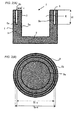
Fig. 1(A) is a sectional view along the A-A line inFig. 1(B) including a central axis of a graphite crucible according to anembodiment 1 of the invention, and -
Fig. 1(B) is a top plan view of the graphite crucible according to theembodiment 1 of the invention. -
Fig. 2(A) is a sectional view including a central axis of a graphite crucible according to anembodiment 2 of the invention, andFig. 2(B) is a top plan view of the graphite crucible according to theembodiment 2 of the invention. -
Fig. 3 shows a binary phase diagram of Si-C. -
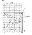
Fig. 4 shows a binary phase diagram of Fe-C. -
Fig. 5 shows a polarization-microscopic photograph of a boundary region between the graphite crucible and the object to be treated (iron) at a divided cross-section after heating according to an embodiment of the invention. - In the invention, the direction toward a bottom part of the graphite crucible is defined to be lower, and the opposite side at which the crucible is opened is defined to be upper.
Fig. 1 shows a graphite crucible according to theembodiment 1 of the invention. Specifically,Fig. 1(A) is a sectional view along the A-A line inFig. 1(B) including a central axis of the graphite crucible according to theembodiment 1 of the invention, andFig. 1(B) is a top plan view of the graphite crucible according to theembodiment 1 of the invention. - In the
embodiment 1 of the invention, the graphite crucible means that graphite is a substantial constitutional component thereof. In the invention, graphite may be any kind of graphite and may be anisotropic graphite such as an extruded material or an embossed material or an isotropic graphite material obtained by cold isostatic molding (CIP molding: Cold Isostatic Press). In particular, the graphite obtained by the CIP molding has high strength since a fine raw material (e.g., cokes having a particle diameter of 10 to 20 µm) can be used, and hence, the texture becomes fine. Moreover, since pressurization is performed using a liquid pressurization medium, an isotropic material can be obtained. Since there is no directivity in thermal expansion coefficient, distorted deformation hardly occurs, and thus, thermal stress caused by the distorted deformation is hardly generated, so that it is possible to make troubles such as cracks less likely to occur. - The
graphite crucible 1 according to theembodiment 1 of the invention is characterized by including abottom part 2, abody part 3, and atreatment part 4 having aninlet port 4a, and further including agas discharge part 5 that is opened at the upper end side of the body part. - In the
graphite crucible 1 according to theembodiment 1 of the invention, a space excluding thegas discharge part 5 from the space between a crucible inner periphery 1a that defines the space of thetreatment part 4 and a crucibleouter periphery 1b is made of graphite. - The
bottom part 2 is a part below aninner bottom surface 2a when the crucible is cut out to the crucible outer periphery by the plane including theinner bottom surface 2a that is a lower end part of the crucible inner periphery 1a. Theinner bottom surface 2a may be a curved surface instead of a planar surface as shown inFig. 1(A) . As the curved surface, there may be a curved surface having an extreme point at the lower end of the crucible inner periphery, where the tangent surface of the extreme point coincides with theinner bottom surface 2a. Thebottom part 2 has anouter bottom surface 2b that corresponds to the lower end surface of the crucibleouter periphery 1b. - The
body part 3 is a part between the crucible inner periphery 1a and the crucibleouter periphery 1b and is a part other than thebottom part 2 of thegraphite crucible 1. - So long as the
gas discharge part 5 is a space (hole) closed at the lower end side and opened at the upper end side of the body part and has a function of discharging a gas, the shape, size, position of the closed port, the number, and the like thereof are not particularly limited. Thegas discharge part 5 shown inFig. 1(A) and Fig. 1(B) is cylindrical and has a closedport 5a at the lower end side and an openedport 5b at the upper end side of the body part, 20 pieces of thegas discharge part 5 are concentrically provided in the body part, and they are provided at such positions that the central angles thereof are mutually separated by almost 18°. The position of the closedport 5a is slightly lower than theinner bottom surface 2a. - The thickness T of the
bottom part 2 is preferably thicker than the minimum value of the distance t between the gasdischarge part periphery 5c and the crucible inner periphery 1a. As for the distance t between the gasdischarge part periphery 5c and the crucible inner periphery 1a, since t of each hole falls within a certain range for each of 20 pieces of the gas discharge part, the smallest one among them is taken as the minimum value. The minimum value is the smallest one of the distances t between the respective gasdischarge part peripheries 5c and the crucible inner periphery 1a. The thickness of thebottom part 2 is a distance between theinner bottom surface 2a and theouter bottom surface 2b. In the case where theinner bottom surface 2a is a curved surface, the thickness is a distance between the above-described tangent surface and theouter bottom surface 2b. Incidentally, the relationship between the thickness of thebottom part 2 and the distance t is the same in the case where the gas discharge part shown in the embodiment ofFig. 2 is employed. - Since the graphite constituting the
graphite crucible 1 is porous, it has many pores inside. Since it has pores, air bubbles are generated in the course of elution of the graphite into the object to be treated at the time of melting and are diffused into the molten object to be treated. On this occasion, gasification of the impurities contained in the object to be treated is enhanced and the bumping of the object to be treated can be prevented. - Furthermore, in the case where the object to be treated contains an oxide, it is reduced by the graphite to generate a gas of CO or CO2, and similarly the gas of CO or CO2 is continuously released as air bubbles into the molten object to be treated. As a result, gasification of the impurities contained in the object to be treated is enhanced, so that it is thought that sudden boiling of the impurities contained in the object to be treated and the bumping can be prevented. Since the bumping can be prevented, it is thought that scattering of the object to be treated into the apparatus and contamination thereof can be prevented.
- The
gas discharge part 5 functions as a discharge port of a gas as described above. Since the graphite crucible is made of graphite that is porous, it has a property that a gas easily permeates even to the outside of the graphite crucible. Depending on the component(s) contained in the object to be treated, a gas is generated from the object to be treated itself or by the reaction with the graphite crucible. - In the case of the object to be treated containing chlorine such as polyvinyl chloride, a chlorine-based gas is generated. For example, in the case where the object to be treated contains fluorine such as polytetrafluoroethylene, a fluorine-based gas is generated. In the case where the object to be treated contains a sulfate salt or a sulfite salt, it reacts with graphite to generate a corrosive gas such as hydrogen sulfide.
- Since the
graphite crucible 1 has thegas discharge part 5, a gas generated by the reaction with the crucible can be discharged to the upper part of the crucible through thegas discharge part 5 of thebody part 3. The gas discharged as such can be rapidly discharged from the melting apparatus by appropriately providing a discharge port of the melting apparatus on the graphite crucible. By providing such agas discharge part 5, it is thought that the corrosive gas that may be generated from the object to be treated itself or by the reaction with the graphite crucible can be effectively prevented from filling the inside of the melting apparatus to corrode the inside of the melting apparatus. - As described above, the thickness T of the
body part 2 is preferably thicker than the minimum value of the distance t between the gasdischarge part periphery 5c and the crucible inner periphery 1 a. The reason will be described below. - When a solid (clumpy or powdery) object to be treated is placed in the
graphite crucible 1 and melted, the object to be treated is reduced in volume in the process thereof and is likely to gather on the bottom of the graphite crucible. In many cases, in order to efficiently use the graphite crucible, the object to be treated is added repeatedly until the object to be treated is sufficiently filled in thetreatment part 4 of the graphite crucible. Therefore, thebottom part 2 of the graphite crucible is in contact with the object to be treated for a longer period of time. Particularly, in the case of melting an iron-based object to be treated, the graphite constituting the graphite crucible becomes easily eluted into the object to be treated. Therefore, as described above, by thickening the thickness T of the bottom part that is in contact with the object to be treated for a long period of time, the graphite crucible can be prevented from having a hole or from damaging. - The
graphite crucible 1 of the invention preferably has a bulk density ranging from 1,700 to 1,850 kg/m3. When the bulk density is 1,850 kg/m3 or less, air bubbles can be continuously fed to melt at the time of the elution of graphite since a sufficient amount of pores are present. When the bulk density is 1,700 kg/m3 or more, the specific surface area of graphite can be decreased, so that the rate of elution can be diminished and the graphite crucible can be made less likely to have a hole. - The
graphite crucible 1 of the invention preferable has an impurity content of 1.0% by mass or less. When the impurity content is 1.0% by mass or less, an impurity layer owing to remaining impurities can be made less likely to be formed on the crucible inner periphery even if the graphite is corroded. Furthermore, thegraphite crucible 1 preferably has an impurity content of 0.1% by mass or less. When the impurity content is 0.1% by mass or less, an impurity layer owing to remaining impurities can be made further less likely to be formed on the crucible inner periphery even if the graphite is corroded. Since the impurities are less likely to accumulate on the crucible inner periphery, the elution of the graphite continuously occurs, and simultaneously with the elution, the gas contained in the pores is released as air bubbles into the molten object to be treated. As a result, it is thought that the components contained in the inside of the molten object to be treated become hardly overheated and bumping can be made less likely to occur. Therefore, it is thought that contamination and damage of the inside of the apparatus caused by bumping can be prevented. - Incidentally, the above action of the
graphite crucible 1 is not limited to the case under atmospheric pressure and it similarly functions even under reduced pressure. Even when the mass of the gas present in the pores of graphite is small under the reduced pressure, the gas can expand and form air bubbles owing to low pressure. - The impurity content of the
graphite crucible 1 is preferably as low as possible, for example, 0% by mass. - The
graphite crucible 1 is preferably a graphite crucible used for melting an iron-based, a silicon-based, a nickel-based, or a titanium-based object to be treated or an object to be treated composed of a mixture thereof. Since these elements form carbides, air bubbles can be generated with consuming the graphite crucible at the time of melting these elements. Therefore, the bumping of the object to be treated can be made less likely to occur. - The mechanism of elution of the graphite constituting the
graphite crucible 1 into the silicon contained in the object to be treated will be described with reference to the Si-C binary phase diagram ofFig. 3 (Micro Structure of Silicon Carbide Grinding Tools; M. Moser, Periodica Polytechnica CH21/1 1976.6.30). InFig. 3 , the abscissa at the lower part represents an element ratio of silicon and the ordinate represents temperature. When silicon is placed in a graphite crucible and heated, the silicon is melted at 1,414°C as shown by 6 in the Si-C binary phase diagram ofFig. 3 . When the temperature is further elevated to 1,600°C, the silicon melt becomes to contain carbon in an amount of about 1% as shown by 7. The carbon concentration of the melt increases with melting the graphite on the surface of the graphite crucible. Since the silicon is melted with melting the graphite and air bubbles are generated from the pores of the graphite, the bumping of the object to be treated can be made less likely to occur. - Incidentally, at the time of melting silicon in the graphite crucible, the surface layer of the graphite crucible forms SiC. Since even SiC is eluted into the melt, air bubbles can be generated.
- With regard to the
graphite crucible 1, in the case of melting an iron-based object to be treated, since temperature is high and also graphite is easily eluted into the object to be treated, thegraphite crucible 1 is easily consumed and air bubbles are easily generated, so that bumping can be effectively prevented. - The mechanism of eluting the graphite constituting the
graphite crucible 1 into the iron contained in the object to be treated will be described with reference to the Fe-C binary phase diagram ofFig. 4 . InFig. 4 (Metal data Book, revised 4th edition, Japan Institute of Metals 2004.2.29), the abscissa at the lower part represents a mass ratio of carbon (% by mass), the abscissa at the upper part represents an element ratio of carbon (atom%), and the ordinate represents temperature. When the iron is heated as shown by the sign 11 in the Fe-C binary phase diagram ofFig. 4 , it is melted at 1,536°C. Since the molten iron dissolves carbon, when the temperature of 1,536°C is still maintained, the elution of carbon ceases at the time when 5.2% by mass (A) of carbon is contained in the melt. During the process, air bubbles are continuously released from the pores of the graphite and hence the bumping of the object to be treated can be made less likely to occur. Incidentally, when the temperature is maintained at 1,536°C, it is adequate for the graphite crucible to have such a sufficient thickness that a graphite material corresponding to 5.2% by mass of the molten material may be eroded from the graphite crucible. When the temperature is further elevated, the saturated concentration of carbon increases. For example, in the case of 1,600°C, the elution of carbon ceases at the time when at most about 5.5% (B) of carbon is contained, which is % by mass of carbon at which the liquidus line 13 from theeutectic point 12 intersects the line of 1,600°C. Therefore, since a larger amount of graphite is eroded when hot treatment temperature is elevated, much more air bubbles can be generated. As a result, bumping can be made less likely to occur even in the use at a high temperature at which bumping easily occurs. Incidentally, erosion should be supposed in an amount of about 5.5% based on the iron contained in the object to be treated in the case of the use at 1,600°C. - Even when the metal contained in the object to be treated is an iron alloy such as stainless steel, graphite is eluted by a similar mechanism.
- When the mass of the object to be treated (iron) is taken as M1, the mass of the carbon (graphite) dissolved into the material to be melted is taken as M2, and the densities are taken as ρ1 (7.8 g/cm3) and ρ2 (1.8 g/cm3) respectively, respective volumes V1 and V2 of the object to be treated (iron) and the carbon (graphite) dissolved into the object to be treated can be calculated as follows, in the case where the dissolved carbon is 5.5% by mass.



- The following equation can be achieved from the equations of (equation 1) to (equation 3).

- When actual numerical values of density (ρ1 = 7.8 g, ρ1 = 1.8) are applied to the
equation 4,
graphite crucible 1 can continuously generate air bubbles with eroding the graphite (carbon) in a volume of about 25% (20/80) of the volume of the iron. As a result, it is thought sufficient that thegraphite crucible 1 has the thickness of the bottom part which satisfies the relationship of the distance between the gasdischarge part periphery 5c and the crucible inner periphery as described above with supposing the erosion of about 25% of the melt in which the material to be melted and the graphite are melted. - In the case where the object to be treated is an iron alloy, since the content of iron is smaller than pure iron, the amount of graphite eluted into the object to be treated is smaller than that in the case of pure iron. In the case where the object to be treated contains a ceramic such as concrete or mortar, the molten material (slag) thereof has high viscosity, the reaction with the graphite only occurs partially at the part with which the slag comes into contact and the slag is less likely to react wholly. Therefore, the influence of the erosion of the graphite crucible by the slag is smaller, so that it is thought sufficient to consider the influence of the metal object to be treated mainly.
- As for the size of the
graphite crucible 1, for example, the outer diameter Ro is 975 mm, the inner diameter Ri is 795 mm, the height h is 900 mm, and the depth d0 is 795 mm. On the body part, 20 pieces of the gas discharge part are provided rotationally symmetrically with the central axis of the graphite crucible being centered. PCD (Pitch Circle Diameter) of the gas discharge part is 920 mm and each gas discharge part has an openedport 5a and aclosed port 5b each having a diameter φ of 20 mm and has a depth d1 of 870 mm. Incidentally, in the case where t is taken as a constant minimum value, the minimum value of t is obtained to be 52.5 mm when calculated as PCD = φ+2t+Ri, and t = (PCD-φ-Ri)/2. - Next, there will be described a graphite crucible according to an
embodiment 2 of the invention. -
Fig. 2(A) is a sectional view including a central axis of the graphite crucible of theembodiment 2 according to the invention, andFig. 2(B) is a top plan view of the graphite crucible according to theembodiment 2 of the invention. - The
graphite crucible 1 according to theembodiment 2 of the invention is configured such that thegas discharge part 5 is provided continuously in a groove shape around the body part in thegraphite crucible 1 of theembodiment 1, in which the minimum value of the distance t between the gasdischarge part periphery 5c and the crucible inner periphery 1a is the same as in theembodiment 1 except that thegas discharge part 5 has a circular ring shape with a constant thickness, and theembodiment 2 has the similar function to theembodiment 1. - In the
present embodiment 2, since the gas discharge part is formed in a groove shape, the gas generated from the inside of the graphite crucible can be made easier to be caught as compared with theembodiment 1. Therefore, it is possible to make the corrosive gas further less likely to reach the melting apparatus around the crucible. The depth d1 of the groove of the gas discharge part is not particularly limited but it is preferable to have such a depth that theclosed port 5a reaches the bottom part of the graphite crucible. When the gas discharge part has such a depth that it reaches the bottom part of the graphite crucible, a larger amount of the gas generated from the inside of the graphite crucible can be caught. - Also in the
embodiment 2 of the invention, it is thought that bumping can be less likely to occur since thegraphite crucible 1 can generate air bubbles in the case where an iron-based, a silicon-based, a nickel-based, or a titanium-based object to be treated, or an object to be treated composed of a mixture thereof is melted, similarly to theembodiment 1. - As for the size of the
graphite crucible 2, for example, the outer diameter Ro is 975 mm, the inner diameter Ri is 795 mm, the height h is 900 mm, and the depth d0 is 795 mm. In the body part, a gas discharge part having an inner diameter Riφ of 900 mm, an outer diameter Roφ of 940 mm, and a depth d1 of 500 mm is formed in a groove shape which surrounds the body part. The minimum value of t is constant and is 52.5 mm. - Since the graphite crucibles of the
embodiments - As the object to be treated which is to be subjected to the treatment in the graphite crucibles of the
embodiments - Next, Examples of the invention will be described, but it should be appreciated that the invention is not limited to these.
- A graphite crucible of the
embodiment 1 shown inFig. 1 was used. - Specifically, a graphite crucible having an outer diameter Ro of 40 mm, an inner diameter Ri of 30 mm, a height h of 40 mm, and a depth d0 of 30 mm was used.
- On the body part of the graphite crucible, 8 pieces of the gas discharge part were provided rotationally symmetrically with the central axis of the graphite crucible being centered. PCD (Pitch Circle Diameter) of the gas discharge part is 36 mm and each gas discharge part has a diameter φ of 2 mm and a depth d1 of 35 mm. The minimum value of t is 2 mm.
- The inner volume (volume of treatment part) of the graphite crucible of the present Example is 21.2 ml and the volume occupied by the graphite crucible (volume of graphite) is 25. 6 ml. The graphite crucible was prepared by cutting a fine carbon material (isotropic graphite): ET-10 manufactured by IBIDEN Co., Ltd. The bulk density of ET-10 that was used for the crucible was 1,750 kg/m3.
- Iron fragments of 50g were placed in the graphite crucible of the invention as an object to be treated, and heated in a heating furnace in an argon atmosphere. On this occasion, the object to be treated was filled into the graphite crucible to the upper end thereof.
- The heating furnace containing the graphite crucible of the present Example was heated at a temperature elevation rate of 500°C/H, and then kept at 1,600°C for 6 hours. Then, it was naturally cooled.
- The graphite crucible of the present Example taken out from the furnace after cooling was not changed in appearance as compared with that before heating, and no mark of iron which might be melted and scattered around the graphite crucible was observed. The object to be treated placed in the graphite crucible of the present Example was melted and the volume was reduced. The graphite crucible of the present Example taken out after cooling was divided into two pieces so as to include the central axis and the cross-section was observed. While the thickness of the bottom part of the graphite crucible was originally 10 mm, it was greatly eroded such that the thickness was diminished to 7 mm, but the erosion did not reach the outer surface.
-
Fig. 5 shows a polarization-microscopic photograph of a boundary region between the graphite crucible and the object to be treated (iron) at a divided cross-section after heating according to the present Example. The polarization microscope was manufactured by Nikon Corporation and an extended image of 25 magnifications was photographed by a collimate method. - It is thought that the left hand in
Fig. 5 is graphite constituting the crucible and the right hand inFig. 5 is cast iron in which the graphite constituting the crucible is dissolved into iron. A striated texture was observed in the cast iron at the right hand inFig. 5 and thus it is realized that once melted graphite is precipitated again through temperature falling. It is presumed that the object to be treated becomes gray cast iron with an increase in carbon content. - A graphite crucible of the
embodiment 2 shown inFig. 2 was used. - Specifically, a graphite crucible having an outer diameter Ro of 40 mm, an inner diameter Ri of 30 mm, a height h of 40 mm, and a depth d0 of 30 mm was used.
- In the body part of the graphite crucible, a gas discharge part having an inner diameter Riφ of 34 mm, an outer diameter Roφ of 38 mm, and a depth d1 of 20 mm is formed in a groove shape which surrounds the body part. The minimum value of t is 2 mm.
- The inner volume (volume of treatment part) of the graphite crucible of the present Example is 21.2 ml and the volume occupied by the graphite crucible (volume of graphite) is 24.6 ml. The graphite crucible was prepared by cutting a fine carbon material (isotropic graphite): ET-10 manufactured by IBIDEN Co., Ltd. The bulk density of ET-10 that was used for the crucible was 1,750 kg/m3.
- The object to be treated same as in Example 1 was placed in the graphite crucible of the invention and was then subjected to a heating treatment in the same manner.
- The graphite crucible of the present Example taken out from the furnace after cooling was not changed in appearance as compared with that before heating, and no mark of iron which might be melted and scattered around the graphite crucible was observed. The object to be treated placed in the graphite crucible of the present Example was melted and the volume was reduced. The graphite crucible of the present Example taken out after cooling was divided into two pieces so as to include the central axis and the cross-section was observed. While the thickness of the bottom part of the graphite crucible was originally 10 mm, it was greatly eroded until the thickness was diminished to 7 mm, but the erosion did not reach the outer surface.
- In Example 1 or 2, a crucible without providing a gas discharge part was used. The material constituting the crucible was not graphite but the crucible was made of magnesia containing magnesium oxide as a main component. The outer diameter Ro is 40 mm, the inner diameter Ri is 30 mm, the height h is 40 mm, the depth d0 is 30 mm, the inner volume (volume of treatment part) of the crucible is 21.2 ml, and the volume occupied by the crucible (volume of magnesia) is 29.1 ml.
- The object to be treated same as in Example 1 was placed in the crucible of the Comparative Example, and was subjected to a heating treatment in the same manner.
- The crucible of Comparative Example 1 taken out from the furnace after cooling was not changed in appearance as compared with that before heating. It seemed that bumping had occurred, and a part of the object to be treated was scattered outside the crucible. The crucible of Comparative Example 1 taken out after cooling was divided into two pieces so as to include the central axis and the cross-section was observed. The inner surface of the crucible was not eroded.
- From the above results, in the graphite crucibles of Examples 1 and 2, it can be confirmed that, even when graphite as a material of the graphite crucibles is melted into iron as an object to be treated, a sufficient thickness remains, no hole is generated and no crack is generated, and the bumping of the object to be treated becomes less likely to occur since air bubbles are generated at the time when the graphite is melted.
- On the other hand, in the crucible of Comparative Example, since the material is made of magnesia that is difficult to melt into the object to be treated, the crucible is hardly consumed by the object to be treated but it is thought that bumping is likely to occur since air bubbles are difficult to generate.
- While the invention has been described in detail and with reference to specific embodiments thereof, it will be apparent to one skilled in the art that various changes and modifications can be made therein without departing from the spirit and scope thereof. The present application is based on Japanese Patent Application No.
2011-171793 filed on August 5, 2011 - The use of the present invention is not particularly limited so long as it is a graphite crucible for melting an iron-based, a silicon-based, a nickel-based, or a titanium-based object to be treated, or an object to be treated composed of a mixture thereof, and can be utilized for crucibles for producing castings, crucibles for reducing the volume of wastes, and the like.
- 1: graphite crucible, 1a: crucible inner periphery, 1b: crucible outer periphery, 2: bottom part, 2a: inner bottom surface, 2b: outer bottom surface, 3: body part, 4: treatment part, 4a: input port, 5: gas discharge part, 5a: closed port, 5b: opened port, 5c: gas discharge part periphery, t: distance between gas discharge part periphery and crucible inner periphery, 6,7: melting point of silicon, 11: melting point of Fe, 12: eutectic point, 13: liquidus line, graphite crucible (Ro: outer diameter, Ri: inner diameter, h: height, d0: depth, T: thickness of bottom part), gas discharge part (φ: diameter, Roφ: outer diameter, Riφ: inner diameter, d1: depth), 15: graphite, 16: iron.
Claims (8)
- A graphite crucible comprising:a bottom part;a body part;a treatment part including an input port; anda gas discharge part that is closed at a lower end side and is opened at an upper end side of the body part.
- The graphite crucible according to claim 1,
wherein the gas discharge part is formed in a groove shape. - The graphite crucible according to claim 1 or 2,
wherein a thickness of the bottom part is thicker than a minimum value of a distance between a periphery of the gas discharge part and an inner periphery of the crucible. - The graphite crucible according to any one of claims 1 to 3,
wherein the graphite crucible has a bulk density ranging from 1,700 to 1,850 kg/m3. - The graphite crucible according to any one of claims 1 to 4,
wherein the graphite crucible has an impurity content of 1.0% by mass or less. - The graphite crucible according to claim 5,
wherein the graphite crucible has an impurity content of 0.1% by mass or less. - The graphite crucible according to any one of claims 1 to 6,
wherein the graphite crucible is used for melting an object to be treated selected from an iron-based object, a silicone-based object, a nickel-based object, or a titanium-based object, and a mixture thereof. - A method for producing a solidified body of an object to be treated using the graphite crucible according to any one of claims 1 to 7.
Applications Claiming Priority (2)
| Application Number | Priority Date | Filing Date | Title |
|---|---|---|---|
| JP2011171793 | 2011-08-05 | ||
| PCT/JP2012/058254 WO2013021677A1 (en) | 2011-08-05 | 2012-03-28 | Graphite crucible |
Publications (2)
| Publication Number | Publication Date |
|---|---|
| EP2741039A1 true EP2741039A1 (en) | 2014-06-11 |
| EP2741039A4 EP2741039A4 (en) | 2015-02-25 |
Family
ID=47668207
Family Applications (1)
| Application Number | Title | Priority Date | Filing Date |
|---|---|---|---|
| EP12822079.5A Withdrawn EP2741039A4 (en) | 2011-08-05 | 2012-03-28 | Graphite crucible |
Country Status (4)
| Country | Link |
|---|---|
| US (1) | US20140147801A1 (en) |
| EP (1) | EP2741039A4 (en) |
| JP (1) | JP6006724B2 (en) |
| WO (1) | WO2013021677A1 (en) |
Cited By (1)
| Publication number | Priority date | Publication date | Assignee | Title |
|---|---|---|---|---|
| CN104843675A (en) * | 2015-06-10 | 2015-08-19 | 四川都江堰西马炭素有限公司 | Powder purifying method and powder purifying apparatus |
Families Citing this family (5)
| Publication number | Priority date | Publication date | Assignee | Title |
|---|---|---|---|---|
| JP6146319B2 (en) * | 2014-01-17 | 2017-06-14 | トヨタ自動車株式会社 | Metal melting equipment |
| EP3590102B1 (en) | 2017-03-01 | 2026-02-18 | Honeywell International Inc. | Access control request manager based on learning profile-based access pathways |
| WO2018160407A1 (en) | 2017-03-01 | 2018-09-07 | Carrier Corporation | Compact encoding of static permissions for real-time access control |
| AU2020243828B2 (en) * | 2019-03-18 | 2026-04-02 | Esyantra Pty Ltd | An energy conversion, storage and retrieval device and method |
| CN118064716A (en) * | 2024-03-18 | 2024-05-24 | 昆明理工大学 | A deoxidation method and deoxidation device for AuCuNi alloy melt |
Family Cites Families (12)
| Publication number | Priority date | Publication date | Assignee | Title |
|---|---|---|---|---|
| JPS59168697U (en) * | 1983-04-26 | 1984-11-12 | 明智セラミックス株式会社 | graphite crucible |
| US4948423A (en) * | 1989-07-21 | 1990-08-14 | Energy Conversion Devices, Inc. | Alloy preparation of hydrogen storage materials |
| DE4117470A1 (en) * | 1990-06-12 | 1992-01-30 | Francesco Pedrazzini | Melting crucible construction for induction melting pure titanium - produces molten titanium which flows easily and does not stick to nor react with the vessel |
| JPH0797263A (en) * | 1993-09-28 | 1995-04-11 | Nisshinbo Ind Inc | Graphite vessel and its production |
| JPH11116336A (en) | 1997-10-15 | 1999-04-27 | Akechi Ceramics Kk | Graphite crucible |
| US6399017B1 (en) * | 2000-06-01 | 2002-06-04 | Aemp Corporation | Method and apparatus for containing and ejecting a thixotropic metal slurry |
| US6613118B2 (en) * | 2001-12-18 | 2003-09-02 | C. Edward Eckert | Method of heating molten aluminum in a crucible |
| FR2835000B1 (en) * | 2002-01-21 | 2004-11-05 | Delachaux Sa | PROCESS FOR THE MANUFACTURE OF METAL ELEMENTS USING A CRUCIBLE |
| JP2004099959A (en) * | 2002-09-06 | 2004-04-02 | Sumitomo Metal Ind Ltd | Method and apparatus for purifying impurity-containing materials |
| US7858022B2 (en) * | 2005-06-09 | 2010-12-28 | Nippon Crucible Co., Ltd. | Crucible-type continuous melting furnace |
| EP1750075A1 (en) * | 2005-08-05 | 2007-02-07 | Vesuvius Becker & Piscantor Grossalmeroder Schmelztiegelwerke GmbH & Co. KG | Crucible for the treatment of molten metal and process for the manufacture thereof |
| WO2008073141A2 (en) * | 2006-05-30 | 2008-06-19 | Howmet Corporation | Melting method using graphite melting vessel |
-
2012
- 2012-03-28 WO PCT/JP2012/058254 patent/WO2013021677A1/en not_active Ceased
- 2012-03-28 US US14/129,547 patent/US20140147801A1/en not_active Abandoned
- 2012-03-28 JP JP2013527908A patent/JP6006724B2/en active Active
- 2012-03-28 EP EP12822079.5A patent/EP2741039A4/en not_active Withdrawn
Cited By (1)
| Publication number | Priority date | Publication date | Assignee | Title |
|---|---|---|---|---|
| CN104843675A (en) * | 2015-06-10 | 2015-08-19 | 四川都江堰西马炭素有限公司 | Powder purifying method and powder purifying apparatus |
Also Published As
| Publication number | Publication date |
|---|---|
| JPWO2013021677A1 (en) | 2015-03-05 |
| US20140147801A1 (en) | 2014-05-29 |
| JP6006724B2 (en) | 2016-10-12 |
| EP2741039A4 (en) | 2015-02-25 |
| WO2013021677A1 (en) | 2013-02-14 |
Similar Documents
| Publication | Publication Date | Title |
|---|---|---|
| US20140147801A1 (en) | Graphite crucible | |
| Warren | Microstructural development during the liquid-phase sintering of two-phase alloys, with special reference to the NbC/Co system | |
| Gao et al. | Effect of interaction of refractories with Ni-based superalloy on inclusions during vacuum induction melting | |
| Gao et al. | Oscillating pressure sintering of W–Ni–Fe refractory alloy | |
| JP6783314B2 (en) | Lead-free free-cutting brass alloy with excellent castability, its manufacturing method, and its applications | |
| Luna et al. | Casting protocols for the production of open cell aluminum foams by the replication technique and the effect on porosity | |
| Qi et al. | Slag resistance mechanism of MgO–Mg2SiO4–SiC–C refractories containing porous multiphase aggregates | |
| Wei et al. | Corrosion of MgO–C refractory with ladle slags | |
| ZHANG et al. | Microstructure and formation process of Ni-pool defect in WC–8Ni cemented carbides | |
| Cho et al. | Surface roughening transition and coarsening of NbC grains in liquid cobalt‐rich matrix | |
| Zhang et al. | Reactive synthesis of porous FeAlCr intermetallics with enhanced mechanical property and oxidation resistance by introducing yttrium borides | |
| Cheng et al. | Reaction Mechanism between MgO and MgO C Lining Refractories and a High‐Carbon Al‐Killed Steel | |
| Wei et al. | Diamonds brazing with a novel Cu35Ni35Cr10Fe10Sn10 high‐entropy alloy filler | |
| Mao et al. | Processing and mechanical behaviour of TiAl/NiAl intermetallic composites produced by cryogenic mechanical alloying | |
| AU2017306581B2 (en) | Metal matrix composite material casting | |
| Huang et al. | Pinning effect of Y2O3 network on copper grain growth during high temperature annealing | |
| Nickel et al. | High temperature corrosion of ceramics and refractory materials | |
| Woydt et al. | The tribological property profile of hard metals and metal matrix composites based on niobium carbide | |
| Saini et al. | Effect of alloying elements on thermal stability of Aluminium-Cerium based alloys | |
| Zhang et al. | Developing chromium-free MgO–ZrO2 refractory with enhanced copper slag corrosion resistance | |
| EP3315475B1 (en) | Brick for hearth section of molten pig iron production furnace | |
| JPH11246919A (en) | Refining method of molten metal | |
| McDougall et al. | Sidewall design to improve lining life in a platinum smelting furnace | |
| Moya et al. | Interfacial reactions in aluminum alloys/mullite–zirconia composites | |
| Luo et al. | Development of inclusions in 3104 alloy melt during heating and holding treatments |
Legal Events
| Date | Code | Title | Description |
|---|---|---|---|
| PUAI | Public reference made under article 153(3) epc to a published international application that has entered the european phase |
Free format text: ORIGINAL CODE: 0009012 |
|
| 17P | Request for examination filed |
Effective date: 20140303 |
|
| AK | Designated contracting states |
Kind code of ref document: A1 Designated state(s): AL AT BE BG CH CY CZ DE DK EE ES FI FR GB GR HR HU IE IS IT LI LT LU LV MC MK MT NL NO PL PT RO RS SE SI SK SM TR |
|
| DAX | Request for extension of the european patent (deleted) | ||
| A4 | Supplementary search report drawn up and despatched |
Effective date: 20150123 |
|
| RIC1 | Information provided on ipc code assigned before grant |
Ipc: F27B 14/10 20060101AFI20150119BHEP |
|
| 17Q | First examination report despatched |
Effective date: 20160104 |
|
| STAA | Information on the status of an ep patent application or granted ep patent |
Free format text: STATUS: THE APPLICATION IS DEEMED TO BE WITHDRAWN |
|
| 18D | Application deemed to be withdrawn |
Effective date: 20160518 |