EP2740985A1 - Raccord rapide avec verrouillage de securité - Google Patents
Raccord rapide avec verrouillage de securité Download PDFInfo
- Publication number
- EP2740985A1 EP2740985A1 EP20130195983 EP13195983A EP2740985A1 EP 2740985 A1 EP2740985 A1 EP 2740985A1 EP 20130195983 EP20130195983 EP 20130195983 EP 13195983 A EP13195983 A EP 13195983A EP 2740985 A1 EP2740985 A1 EP 2740985A1
- Authority
- EP
- European Patent Office
- Prior art keywords
- safety slide
- slide
- securing
- safety
- recess
- Prior art date
- Legal status (The legal status is an assumption and is not a legal conclusion. Google has not performed a legal analysis and makes no representation as to the accuracy of the status listed.)
- Granted
Links
- 238000010168 coupling process Methods 0.000 title claims description 44
- 230000008878 coupling Effects 0.000 title claims description 41
- 238000005859 coupling reaction Methods 0.000 title claims description 41
- 238000006073 displacement reaction Methods 0.000 claims description 15
- 210000003127 knee Anatomy 0.000 claims description 2
- 230000008901 benefit Effects 0.000 description 2
- 230000005540 biological transmission Effects 0.000 description 2
- 230000007246 mechanism Effects 0.000 description 2
- 230000009471 action Effects 0.000 description 1
- 230000003213 activating effect Effects 0.000 description 1
- 238000011161 development Methods 0.000 description 1
- 230000018109 developmental process Effects 0.000 description 1
- 230000000694 effects Effects 0.000 description 1
- 238000007789 sealing Methods 0.000 description 1
Images


Classifications
-
- F—MECHANICAL ENGINEERING; LIGHTING; HEATING; WEAPONS; BLASTING
- F16—ENGINEERING ELEMENTS AND UNITS; GENERAL MEASURES FOR PRODUCING AND MAINTAINING EFFECTIVE FUNCTIONING OF MACHINES OR INSTALLATIONS; THERMAL INSULATION IN GENERAL
- F16L—PIPES; JOINTS OR FITTINGS FOR PIPES; SUPPORTS FOR PIPES, CABLES OR PROTECTIVE TUBING; MEANS FOR THERMAL INSULATION IN GENERAL
- F16L25/00—Constructive types of pipe joints not provided for in groups F16L13/00 - F16L23/00 ; Details of pipe joints not otherwise provided for, e.g. electrically conducting or insulating means
- F16L25/009—Combination of a quick-acting type coupling and a conventional one
-
- F—MECHANICAL ENGINEERING; LIGHTING; HEATING; WEAPONS; BLASTING
- F16—ENGINEERING ELEMENTS AND UNITS; GENERAL MEASURES FOR PRODUCING AND MAINTAINING EFFECTIVE FUNCTIONING OF MACHINES OR INSTALLATIONS; THERMAL INSULATION IN GENERAL
- F16L—PIPES; JOINTS OR FITTINGS FOR PIPES; SUPPORTS FOR PIPES, CABLES OR PROTECTIVE TUBING; MEANS FOR THERMAL INSULATION IN GENERAL
- F16L37/00—Couplings of the quick-acting type
- F16L37/08—Couplings of the quick-acting type in which the connection between abutting or axially overlapping ends is maintained by locking members
- F16L37/12—Couplings of the quick-acting type in which the connection between abutting or axially overlapping ends is maintained by locking members using hooks, pawls or other movable or insertable locking members
- F16L37/14—Joints secured by inserting between mating surfaces an element, e.g. a piece of wire, a pin, a chain
- F16L37/15—Joints secured by inserting between mating surfaces an element, e.g. a piece of wire, a pin, a chain the element being a wedge
-
- F—MECHANICAL ENGINEERING; LIGHTING; HEATING; WEAPONS; BLASTING
- F16—ENGINEERING ELEMENTS AND UNITS; GENERAL MEASURES FOR PRODUCING AND MAINTAINING EFFECTIVE FUNCTIONING OF MACHINES OR INSTALLATIONS; THERMAL INSULATION IN GENERAL
- F16L—PIPES; JOINTS OR FITTINGS FOR PIPES; SUPPORTS FOR PIPES, CABLES OR PROTECTIVE TUBING; MEANS FOR THERMAL INSULATION IN GENERAL
- F16L37/00—Couplings of the quick-acting type
- F16L37/08—Couplings of the quick-acting type in which the connection between abutting or axially overlapping ends is maintained by locking members
- F16L37/12—Couplings of the quick-acting type in which the connection between abutting or axially overlapping ends is maintained by locking members using hooks, pawls or other movable or insertable locking members
- F16L37/18—Joints tightened by eccentrics or rotatable cams
-
- F—MECHANICAL ENGINEERING; LIGHTING; HEATING; WEAPONS; BLASTING
- F16—ENGINEERING ELEMENTS AND UNITS; GENERAL MEASURES FOR PRODUCING AND MAINTAINING EFFECTIVE FUNCTIONING OF MACHINES OR INSTALLATIONS; THERMAL INSULATION IN GENERAL
- F16L—PIPES; JOINTS OR FITTINGS FOR PIPES; SUPPORTS FOR PIPES, CABLES OR PROTECTIVE TUBING; MEANS FOR THERMAL INSULATION IN GENERAL
- F16L37/00—Couplings of the quick-acting type
- F16L37/56—Couplings of the quick-acting type for double-walled or multi-channel pipes or pipe assemblies
Definitions
- the invention relates to a quick coupling for connecting at least two pressurized lines with a first and a second, each to be connected line connections bearing connection block, wherein the first and the second connection block by means of a rotatably mounted on one of the connection blocks and the coupling process on the another connection block mounted receiving element in a control cam engaging the clutch lever can be brought together in a pressure-tight connection.
- a generic quick coupling with the above features is in the DE 10 2004 055 001 A1 described.
- the line connections for the lines to be connected by means of the quick connector are arranged, and on the other hand on the opposite sides of the two connection blocks on the one connection block corresponding to each line connection associated male connector part and on the other connection block a corresponding each sleeve connection associated female sleeve part for sealingly receiving the male part in the coupling position of the connecting blocks.
- This coupling position is to bring about the operation of a clutch lever which is rotatably mounted on one of the two connecting blocks and the coupling process on detected the respective other connection block mounted receiving element and in a control curve leads such that the two connecting blocks are pulled against each other.
- the clutch lever should be lockable in its coupling position. Accordingly, the clutch lever releases the receiving element when uncoupling the clutch again.
- a quick connector receptacle for attaching a working device or its adapter in a receptacle wherein an inner tube end of the adapter is to be received in a holding opening of the receptacle and a locking mechanism locks the adapter within the holding opening.
- the associated contact surfaces of adapter and receptacle each have a Z-shaped structure.
- a locking mechanism a movable by means of a handle locking pin is provided which eccentrically from a release position in which its center is outside the retaining opening in the receptacle, in a locking position in which its center is moved further into the retaining opening rotates.
- the invention has for its object to provide a known quick coupling with the generic features with an additional backup of the coupling state.
- the invention provides in its basic idea an additional safety lock in that for securing the coupling position of the first and second connection block is provided in an aligned in the two connection blocks bore plug-in and axially on one of the connection blocks supporting safety bolt is provided in his in the another plane lying block has a transversely passing through him recess for receiving a transverse to the longitudinal axis of the securing bolt arranged in the other connecting block fuse slide, wherein the safety slide in its lying in the recess of the securing bolt securing position, the recess of the locking bolt traversed transversely and on both sides of the securing bolt receiving bore in which the fuse slide leading connection block is supported, and between its securing position and an outside of the recess of the Sich ceremoniessb Olzens located release position is axially displaceable by means of an attacking on the safety slide actuator.
- the safety slide in its securing position, the recess of the locking bolt transversely traversed and supported on both sides of the securing bolt receiving bore in the fuse slide leading connection block, whereby a good power transmission between the two connection blocks is realized.
- the safety slide is formed a wedge shape with a perpendicular to the longitudinal axis of the locking bolt surface and with an opposite inclined at a wedge angle surface, wherein the securing slide in the securing position receiving recess of the locking bolt to the Has surfaces of the safety slide congruent surfaces, so that with an increasing retraction of the safety slide in the recess of the locking bolt an increase in the force acting in the axis of the securing bolt connection force takes place.
- the wedge angle of the surfaces of safety slide and recess is designed such that adjusts a self-locking of the spline connection between safety slide and safety pin; In this way, an automatic release of the safety lock is excluded.
- the safety slide is provided at its front end with a chamfer.
- the actuation consists of a in which the safety slide having connection block rotatably arranged sleeve and at least a part its longitudinal extension of the sleeve covered safety slide with at least one pin radially projecting from it is guided in a helical link of the sleeve in such a way that a rotation of the sleeve is converted into an axial displacement of the safety slide, wherein the sleeve is rotatable by means of a handle engaging with it and located outside the connecting block.
- the operation for the axial displacement of the safety slide consists of a on the safety slide having connecting block rotatably arranged threaded rod on which the safety slide is arranged and guided such that a rotation of the threaded rod in an axial displacement the locking slide is implemented, wherein the threaded rod is rotatable by means of an attacking on her, located outside of the connecting block handle.
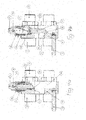
- FIG. 1 apparent quick coupling has a first lower connection block 10 which has on its underside line connections 11 for connecting the respective lines to be connected by means of the quick coupling, wherein the line terminals 11 on the top of the connection block 10 plug-in parts 12 are assigned to the sealing engagement in accordance with a second upper connecting block 20 formed sleeve parts 28 are arranged. Furthermore, a centering pin 13 protrudes from the upper side of the first connecting block 10 and is adapted for engagement in an opening 27 (corresponding to the second connecting block 20). FIG. 3 ) is established and when moving the two connecting blocks 10, 20 when coupling the quick coupling, the two connecting blocks against each other.
- a U-shaped and the connecting block 10 between its arms outside bordering clutch lever 14 is arranged, which has at the end of its two arms each one above the first connecting block 10 projecting on one side open gate 15, in which a on the second connection block 20 each receiving element 29 is received, so that in the corresponding pivoting of the coupling lever 14 at the in FIG. 1 shown arrangement in the counterclockwise direction, the two connecting blocks 10, 20 are brought into mutual contact, as from FIG. 2 seen.
- Such a design of the connecting blocks including the arrangement of the coupling lever is of the generic type DE 10 2004 055 001 A1 known, so that with regard to the relevant structure of the quick coupling to the disclosure in the aforementioned DE 10 2004 055 001 A1 Reference is made.
- a handle 38 for the operation of one of the additional security locking to be described below.
- FIG. 1 apparent second connection block 20 turn corresponding line connections 11 are formed, as well as the associated sleeve parts 28th
- FIG. 3 the first part of the additional safety lock according to the invention forming safety bolt 22 can be seen, which is inserted in the illustrated embodiment in a centrally disposed between the line connections 11 bore 21 and with a mounted at its upper end circumferential flange 23 on the second, upper connection block 20 is supported.
- the securing bolt 22 In its over the plane of the upper connecting block 20 protruding and thus abutting connecting blocks 10, 20 in the plane of the lower first connecting block 10 reaching end of the securing bolt 22 is provided with a transverse to its longitudinal axis passing through recess 24 having an upper recess surface 25th and an opposite lower recess surface 26 is formed.
- FIG. 4a results in the second upper connecting block 20 associated lower first connecting block 10, where the line terminals 11, the centering pin 13 and the plug-in parts 12 can be seen.
- the lower connection block 10 likewise has a bore 21 which is aligned with the bore 21 in the second connection block 20 and in which the securing bolts 22 inserted into the bore 21 of the upper second connection block 20 come to lie in adjacent connection blocks 10, 20.
- a channel 30 is formed, in which a safety slide 31 is arranged, in its in FIG. 4a shown position is in the release position, in which the safety slide 31 is outside the bore 21 in the first connection block 10.
- the safety slide 31 by means of an actuator to be described in the channel 30 axially displaceable in a securing position in which the safety slide 31 passes through the bore 21 transversely. Is located accordingly FIG. 5 in adjacent connecting blocks 10, 20 of the securing bolt 22 in the bore 21, so the recess 24 is aligned with the channel 30, so that as shown in FIG FIG. 5 in the securing position of the safety slide 31 also the recess 24 of the locking bolt 22 transversely traversed.
- the safety slide 31 at its front end a chamfer 32 for retraction into the recess 24 and extends in its securing position according to FIG. 5 beyond the bore 21 or the securing bolt 22, so that the front end of the securing slide 31 in turn is supported in the opposite region of the channel 30 in the first connecting block 10.
- the safety slide 31 has a wedge shape with a perpendicular to the longitudinal axis of the securing bolt 22 aligned upper surface 31a and with an opposite, inclined at a wedge angle surface 31b. Accordingly, the upper recess surface 25 and the lower recess surface 26 of the recess 24 in the securing bolt 22 have a corresponding orientation, which means that the lower recess surface 26 in the illustrated embodiment also extends at a corresponding wedge angle.
- This wedge angle is preferably designed such that a self-locking of the spline connection between safety slide 31 and safety pin 22 sets. For the axial movement of the safety slide 31 is in the in FIGS.
- the sleeve 33 is rotatably mounted in a screwed into the outgoing end of the channel 30 bearing bush 36, wherein at its protruding beyond the bearing bush 36 end of the sleeve forms a wave-shaped projection 37 which carries a handle 38.
- the handle 38 By rotation of the handle 38, the sleeve 33 is rotated, which is converted into the axial movement of the safety slide 31.
- FIG. 6 illustrated embodiment differs from the embodiment described in detail above only in that the axial displacement of the safety slide 31 in the channel 30, a threaded rod 40 is provided on which the safety slide 31 is slidably guided with a corresponding thread, wherein on the above the associated connection block 10 protruding End of the threaded rod 40 in turn a handle 38 for the rotation of the threaded rod 40 is arranged.
Landscapes
- Engineering & Computer Science (AREA)
- General Engineering & Computer Science (AREA)
- Mechanical Engineering (AREA)
- Quick-Acting Or Multi-Walled Pipe Joints (AREA)
Applications Claiming Priority (1)
| Application Number | Priority Date | Filing Date | Title |
|---|---|---|---|
| DE102012111947 | 2012-12-07 |
Publications (2)
| Publication Number | Publication Date |
|---|---|
| EP2740985A1 true EP2740985A1 (fr) | 2014-06-11 |
| EP2740985B1 EP2740985B1 (fr) | 2015-09-09 |
Family
ID=49911118
Family Applications (1)
| Application Number | Title | Priority Date | Filing Date |
|---|---|---|---|
| EP13195983.5A Active EP2740985B1 (fr) | 2012-12-07 | 2013-12-06 | Raccord rapide avec verrouillage de securité |
Country Status (1)
| Country | Link |
|---|---|
| EP (1) | EP2740985B1 (fr) |
Cited By (8)
| Publication number | Priority date | Publication date | Assignee | Title |
|---|---|---|---|---|
| CN105065826A (zh) * | 2015-09-17 | 2015-11-18 | 浙江松乔气动液压有限公司 | 多路快速接头组合 |
| WO2017190824A1 (fr) * | 2016-05-02 | 2017-11-09 | Eisele Pneumatics Gmbh & Co. Kg | Dispositif d'accouplement |
| WO2019099354A1 (fr) * | 2017-11-20 | 2019-05-23 | Parker-Hannifin Corporation | Mécanisme de verrouillage permettant de multiples couplages |
| CN109931454A (zh) * | 2019-03-14 | 2019-06-25 | 哈尔滨工程大学 | 一种水下快速换接装置 |
| EP3569911A1 (fr) * | 2018-05-16 | 2019-11-20 | FASTER S.r.l. | Accouplement hydraulique et/ou pneumatique, en particulier du type à connexions multiples |
| USD868948S1 (en) | 2018-02-09 | 2019-12-03 | Cnh Industrial America Llc | Hydraulic multi-coupler having an optional port |
| USD869615S1 (en) | 2018-02-09 | 2019-12-10 | Cnh Industrial America Llc | Hydraulic multi-coupler having an interference tab |
| SE2251253A1 (en) * | 2022-10-28 | 2023-10-24 | Aaloe Ab | A multi-coupling device and a working vehicle |
Citations (3)
| Publication number | Priority date | Publication date | Assignee | Title |
|---|---|---|---|---|
| EP0682203A1 (fr) * | 1994-05-13 | 1995-11-15 | Baha Management B.V. | Dispositif de raccordement |
| DE102006060005A1 (de) * | 2006-03-31 | 2007-10-25 | Liebherr-Hydraulikbagger Gmbh | Schnellkupplung |
| WO2008058301A1 (fr) * | 2006-11-15 | 2008-05-22 | Josef Martin Gmbh & Co. Kg | Système de couplage pour conduites, en particulier pour conduites hydrauliques |
-
2013
- 2013-12-06 EP EP13195983.5A patent/EP2740985B1/fr active Active
Patent Citations (3)
| Publication number | Priority date | Publication date | Assignee | Title |
|---|---|---|---|---|
| EP0682203A1 (fr) * | 1994-05-13 | 1995-11-15 | Baha Management B.V. | Dispositif de raccordement |
| DE102006060005A1 (de) * | 2006-03-31 | 2007-10-25 | Liebherr-Hydraulikbagger Gmbh | Schnellkupplung |
| WO2008058301A1 (fr) * | 2006-11-15 | 2008-05-22 | Josef Martin Gmbh & Co. Kg | Système de couplage pour conduites, en particulier pour conduites hydrauliques |
Cited By (13)
| Publication number | Priority date | Publication date | Assignee | Title |
|---|---|---|---|---|
| CN105065826B (zh) * | 2015-09-17 | 2018-05-22 | 浙江松乔气动液压有限公司 | 多路快速接头组合 |
| CN105065826A (zh) * | 2015-09-17 | 2015-11-18 | 浙江松乔气动液压有限公司 | 多路快速接头组合 |
| US11215307B2 (en) | 2016-05-02 | 2022-01-04 | Eisele Gmbh | Coupling device |
| WO2017190824A1 (fr) * | 2016-05-02 | 2017-11-09 | Eisele Pneumatics Gmbh & Co. Kg | Dispositif d'accouplement |
| WO2019099354A1 (fr) * | 2017-11-20 | 2019-05-23 | Parker-Hannifin Corporation | Mécanisme de verrouillage permettant de multiples couplages |
| US11041584B2 (en) | 2017-11-20 | 2021-06-22 | Parker-Hannifin Corporation | Latch mechanism for multi-coupling |
| USD868948S1 (en) | 2018-02-09 | 2019-12-03 | Cnh Industrial America Llc | Hydraulic multi-coupler having an optional port |
| USD869615S1 (en) | 2018-02-09 | 2019-12-10 | Cnh Industrial America Llc | Hydraulic multi-coupler having an interference tab |
| EP3569911A1 (fr) * | 2018-05-16 | 2019-11-20 | FASTER S.r.l. | Accouplement hydraulique et/ou pneumatique, en particulier du type à connexions multiples |
| CN109931454A (zh) * | 2019-03-14 | 2019-06-25 | 哈尔滨工程大学 | 一种水下快速换接装置 |
| CN109931454B (zh) * | 2019-03-14 | 2023-10-13 | 哈尔滨工程大学 | 一种水下快速换接装置 |
| SE2251253A1 (en) * | 2022-10-28 | 2023-10-24 | Aaloe Ab | A multi-coupling device and a working vehicle |
| SE545554C2 (en) * | 2022-10-28 | 2023-10-24 | Aaloe Ab | A multi-coupling device and a working vehicle |
Also Published As
| Publication number | Publication date |
|---|---|
| EP2740985B1 (fr) | 2015-09-09 |
Similar Documents
| Publication | Publication Date | Title |
|---|---|---|
| EP2740985B1 (fr) | Raccord rapide avec verrouillage de securité | |
| EP1463902B1 (fr) | Dispositif a raccords multiples | |
| EP1743994B1 (fr) | Serrure pour sortie de secours | |
| EP2923418B1 (fr) | Mécanisme de verrouillage pour connecteur enfichable | |
| DE102011118099A1 (de) | Vorrichtung zum Verbinden zweier Leitungsabschnitte | |
| DE69911362T2 (de) | Anordnung zum Verbinden zweier rohrförmiger Elemente | |
| EP2771606A1 (fr) | Unité d'assemblage | |
| EP3491282A1 (fr) | Élément de retenue et raccord doté d'un tel élément de retenue | |
| EP3135574B1 (fr) | Couplage | |
| WO2007101516A1 (fr) | Dispositif d'accouplement à raccords multiples | |
| DE3704159C2 (fr) | ||
| EP1985907B1 (fr) | Couplage de fermeture rapide | |
| EP2707639B1 (fr) | Dispositif de jonction et système de jonction muni d'un tel dispositif | |
| AT503556B1 (de) | Kupplungseinrichtung für leitungen, insbesondere für hydraulikleitungen | |
| DE19501882C2 (de) | Medizinisches Instrument | |
| EP1896219B1 (fr) | Point de raccordement | |
| DE3624135C2 (fr) | ||
| DE4111522C2 (de) | Wechselsystem für Werkzeuge an Bediengeräten | |
| EP2105645A1 (fr) | Raccord enfichable pour fluide doté d'une sécurité contre l'ouverture | |
| EP3299543B1 (fr) | Barillet | |
| EP1978290A1 (fr) | Dispositif destiné au raccordement d'une conduite tubulaire, en particulier d'un tuyau flexible, sur un élément de raccordement | |
| EP1464883B1 (fr) | Raccord rapide à eventage sans moyens de retenue additionnels | |
| DE2237024C3 (de) | Schnellkupplung für Flüssigkeits- und Gasleitungen | |
| WO2016091326A1 (fr) | Pièce de logement d'un embrayage à sec d'un embrayage à sec pour liquides ainsi qu'embrayage à sec pour liquides équipé ce celle-ci | |
| EP3821687A1 (fr) | Dispositif de couplage |
Legal Events
| Date | Code | Title | Description |
|---|---|---|---|
| PUAI | Public reference made under article 153(3) epc to a published international application that has entered the european phase |
Free format text: ORIGINAL CODE: 0009012 |
|
| 17P | Request for examination filed |
Effective date: 20131206 |
|
| AK | Designated contracting states |
Kind code of ref document: A1 Designated state(s): AL AT BE BG CH CY CZ DE DK EE ES FI FR GB GR HR HU IE IS IT LI LT LU LV MC MK MT NL NO PL PT RO RS SE SI SK SM TR |
|
| AX | Request for extension of the european patent |
Extension state: BA ME |
|
| R17P | Request for examination filed (corrected) |
Effective date: 20141121 |
|
| RBV | Designated contracting states (corrected) |
Designated state(s): AL AT BE BG CH CY CZ DE DK EE ES FI FR GB GR HR HU IE IS IT LI LT LU LV MC MK MT NL NO PL PT RO RS SE SI SK SM TR |
|
| GRAP | Despatch of communication of intention to grant a patent |
Free format text: ORIGINAL CODE: EPIDOSNIGR1 |
|
| RIC1 | Information provided on ipc code assigned before grant |
Ipc: F16L 25/00 20060101AFI20150311BHEP Ipc: F16L 37/56 20060101ALI20150311BHEP Ipc: F16L 37/15 20060101ALI20150311BHEP |
|
| INTG | Intention to grant announced |
Effective date: 20150408 |
|
| GRAS | Grant fee paid |
Free format text: ORIGINAL CODE: EPIDOSNIGR3 |
|
| GRAA | (expected) grant |
Free format text: ORIGINAL CODE: 0009210 |
|
| AK | Designated contracting states |
Kind code of ref document: B1 Designated state(s): AL AT BE BG CH CY CZ DE DK EE ES FI FR GB GR HR HU IE IS IT LI LT LU LV MC MK MT NL NO PL PT RO RS SE SI SK SM TR |
|
| REG | Reference to a national code |
Ref country code: GB Ref legal event code: FG4D Free format text: NOT ENGLISH |
|
| REG | Reference to a national code |
Ref country code: AT Ref legal event code: REF Ref document number: 748420 Country of ref document: AT Kind code of ref document: T Effective date: 20150915 Ref country code: CH Ref legal event code: EP |
|
| REG | Reference to a national code |
Ref country code: IE Ref legal event code: FG4D Free format text: LANGUAGE OF EP DOCUMENT: GERMAN |
|
| REG | Reference to a national code |
Ref country code: DE Ref legal event code: R096 Ref document number: 502013001137 Country of ref document: DE |
|
| REG | Reference to a national code |
Ref country code: SE Ref legal event code: TRGR |
|
| REG | Reference to a national code |
Ref country code: FR Ref legal event code: PLFP Year of fee payment: 3 |
|
| REG | Reference to a national code |
Ref country code: FR Ref legal event code: PLFP Year of fee payment: 3 |
|
| REG | Reference to a national code |
Ref country code: NL Ref legal event code: MP Effective date: 20150909 |
|
| PG25 | Lapsed in a contracting state [announced via postgrant information from national office to epo] |
Ref country code: LT Free format text: LAPSE BECAUSE OF FAILURE TO SUBMIT A TRANSLATION OF THE DESCRIPTION OR TO PAY THE FEE WITHIN THE PRESCRIBED TIME-LIMIT Effective date: 20150909 Ref country code: FI Free format text: LAPSE BECAUSE OF FAILURE TO SUBMIT A TRANSLATION OF THE DESCRIPTION OR TO PAY THE FEE WITHIN THE PRESCRIBED TIME-LIMIT Effective date: 20150909 Ref country code: GR Free format text: LAPSE BECAUSE OF FAILURE TO SUBMIT A TRANSLATION OF THE DESCRIPTION OR TO PAY THE FEE WITHIN THE PRESCRIBED TIME-LIMIT Effective date: 20151210 Ref country code: NO Free format text: LAPSE BECAUSE OF FAILURE TO SUBMIT A TRANSLATION OF THE DESCRIPTION OR TO PAY THE FEE WITHIN THE PRESCRIBED TIME-LIMIT Effective date: 20151209 Ref country code: LV Free format text: LAPSE BECAUSE OF FAILURE TO SUBMIT A TRANSLATION OF THE DESCRIPTION OR TO PAY THE FEE WITHIN THE PRESCRIBED TIME-LIMIT Effective date: 20150909 |
|
| REG | Reference to a national code |
Ref country code: LT Ref legal event code: MG4D |
|
| PG25 | Lapsed in a contracting state [announced via postgrant information from national office to epo] |
Ref country code: ES Free format text: LAPSE BECAUSE OF FAILURE TO SUBMIT A TRANSLATION OF THE DESCRIPTION OR TO PAY THE FEE WITHIN THE PRESCRIBED TIME-LIMIT Effective date: 20150909 Ref country code: RS Free format text: LAPSE BECAUSE OF FAILURE TO SUBMIT A TRANSLATION OF THE DESCRIPTION OR TO PAY THE FEE WITHIN THE PRESCRIBED TIME-LIMIT Effective date: 20150909 Ref country code: HR Free format text: LAPSE BECAUSE OF FAILURE TO SUBMIT A TRANSLATION OF THE DESCRIPTION OR TO PAY THE FEE WITHIN THE PRESCRIBED TIME-LIMIT Effective date: 20150909 |
|
| PG25 | Lapsed in a contracting state [announced via postgrant information from national office to epo] |
Ref country code: NL Free format text: LAPSE BECAUSE OF FAILURE TO SUBMIT A TRANSLATION OF THE DESCRIPTION OR TO PAY THE FEE WITHIN THE PRESCRIBED TIME-LIMIT Effective date: 20150909 |
|
| PG25 | Lapsed in a contracting state [announced via postgrant information from national office to epo] |
Ref country code: EE Free format text: LAPSE BECAUSE OF FAILURE TO SUBMIT A TRANSLATION OF THE DESCRIPTION OR TO PAY THE FEE WITHIN THE PRESCRIBED TIME-LIMIT Effective date: 20150909 Ref country code: CZ Free format text: LAPSE BECAUSE OF FAILURE TO SUBMIT A TRANSLATION OF THE DESCRIPTION OR TO PAY THE FEE WITHIN THE PRESCRIBED TIME-LIMIT Effective date: 20150909 Ref country code: IS Free format text: LAPSE BECAUSE OF FAILURE TO SUBMIT A TRANSLATION OF THE DESCRIPTION OR TO PAY THE FEE WITHIN THE PRESCRIBED TIME-LIMIT Effective date: 20160109 Ref country code: SK Free format text: LAPSE BECAUSE OF FAILURE TO SUBMIT A TRANSLATION OF THE DESCRIPTION OR TO PAY THE FEE WITHIN THE PRESCRIBED TIME-LIMIT Effective date: 20150909 Ref country code: IT Free format text: LAPSE BECAUSE OF FAILURE TO SUBMIT A TRANSLATION OF THE DESCRIPTION OR TO PAY THE FEE WITHIN THE PRESCRIBED TIME-LIMIT Effective date: 20150909 |
|
| PG25 | Lapsed in a contracting state [announced via postgrant information from national office to epo] |
Ref country code: RO Free format text: LAPSE BECAUSE OF FAILURE TO SUBMIT A TRANSLATION OF THE DESCRIPTION OR TO PAY THE FEE WITHIN THE PRESCRIBED TIME-LIMIT Effective date: 20150909 Ref country code: PL Free format text: LAPSE BECAUSE OF FAILURE TO SUBMIT A TRANSLATION OF THE DESCRIPTION OR TO PAY THE FEE WITHIN THE PRESCRIBED TIME-LIMIT Effective date: 20150909 Ref country code: BE Free format text: LAPSE BECAUSE OF NON-PAYMENT OF DUE FEES Effective date: 20151231 Ref country code: PT Free format text: LAPSE BECAUSE OF FAILURE TO SUBMIT A TRANSLATION OF THE DESCRIPTION OR TO PAY THE FEE WITHIN THE PRESCRIBED TIME-LIMIT Effective date: 20160111 |
|
| REG | Reference to a national code |
Ref country code: DE Ref legal event code: R097 Ref document number: 502013001137 Country of ref document: DE |
|
| PLBE | No opposition filed within time limit |
Free format text: ORIGINAL CODE: 0009261 |
|
| STAA | Information on the status of an ep patent application or granted ep patent |
Free format text: STATUS: NO OPPOSITION FILED WITHIN TIME LIMIT |
|
| PG25 | Lapsed in a contracting state [announced via postgrant information from national office to epo] |
Ref country code: MC Free format text: LAPSE BECAUSE OF FAILURE TO SUBMIT A TRANSLATION OF THE DESCRIPTION OR TO PAY THE FEE WITHIN THE PRESCRIBED TIME-LIMIT Effective date: 20150909 Ref country code: LU Free format text: LAPSE BECAUSE OF FAILURE TO SUBMIT A TRANSLATION OF THE DESCRIPTION OR TO PAY THE FEE WITHIN THE PRESCRIBED TIME-LIMIT Effective date: 20151206 |
|
| 26N | No opposition filed |
Effective date: 20160610 |
|
| PG25 | Lapsed in a contracting state [announced via postgrant information from national office to epo] |
Ref country code: DK Free format text: LAPSE BECAUSE OF FAILURE TO SUBMIT A TRANSLATION OF THE DESCRIPTION OR TO PAY THE FEE WITHIN THE PRESCRIBED TIME-LIMIT Effective date: 20150909 Ref country code: SI Free format text: LAPSE BECAUSE OF FAILURE TO SUBMIT A TRANSLATION OF THE DESCRIPTION OR TO PAY THE FEE WITHIN THE PRESCRIBED TIME-LIMIT Effective date: 20150909 |
|
| REG | Reference to a national code |
Ref country code: IE Ref legal event code: MM4A |
|
| PG25 | Lapsed in a contracting state [announced via postgrant information from national office to epo] |
Ref country code: IE Free format text: LAPSE BECAUSE OF NON-PAYMENT OF DUE FEES Effective date: 20151206 |
|
| REG | Reference to a national code |
Ref country code: FR Ref legal event code: PLFP Year of fee payment: 4 |
|
| PG25 | Lapsed in a contracting state [announced via postgrant information from national office to epo] |
Ref country code: HU Free format text: LAPSE BECAUSE OF FAILURE TO SUBMIT A TRANSLATION OF THE DESCRIPTION OR TO PAY THE FEE WITHIN THE PRESCRIBED TIME-LIMIT; INVALID AB INITIO Effective date: 20131206 Ref country code: BG Free format text: LAPSE BECAUSE OF FAILURE TO SUBMIT A TRANSLATION OF THE DESCRIPTION OR TO PAY THE FEE WITHIN THE PRESCRIBED TIME-LIMIT Effective date: 20150909 |
|
| PG25 | Lapsed in a contracting state [announced via postgrant information from national office to epo] |
Ref country code: CY Free format text: LAPSE BECAUSE OF FAILURE TO SUBMIT A TRANSLATION OF THE DESCRIPTION OR TO PAY THE FEE WITHIN THE PRESCRIBED TIME-LIMIT Effective date: 20150909 |
|
| REG | Reference to a national code |
Ref country code: CH Ref legal event code: PL |
|
| PG25 | Lapsed in a contracting state [announced via postgrant information from national office to epo] |
Ref country code: MT Free format text: LAPSE BECAUSE OF FAILURE TO SUBMIT A TRANSLATION OF THE DESCRIPTION OR TO PAY THE FEE WITHIN THE PRESCRIBED TIME-LIMIT Effective date: 20150909 |
|
| PG25 | Lapsed in a contracting state [announced via postgrant information from national office to epo] |
Ref country code: CH Free format text: LAPSE BECAUSE OF NON-PAYMENT OF DUE FEES Effective date: 20161231 Ref country code: LI Free format text: LAPSE BECAUSE OF NON-PAYMENT OF DUE FEES Effective date: 20161231 |
|
| REG | Reference to a national code |
Ref country code: FR Ref legal event code: PLFP Year of fee payment: 5 |
|
| PG25 | Lapsed in a contracting state [announced via postgrant information from national office to epo] |
Ref country code: SM Free format text: LAPSE BECAUSE OF FAILURE TO SUBMIT A TRANSLATION OF THE DESCRIPTION OR TO PAY THE FEE WITHIN THE PRESCRIBED TIME-LIMIT Effective date: 20150909 |
|
| PG25 | Lapsed in a contracting state [announced via postgrant information from national office to epo] |
Ref country code: MK Free format text: LAPSE BECAUSE OF FAILURE TO SUBMIT A TRANSLATION OF THE DESCRIPTION OR TO PAY THE FEE WITHIN THE PRESCRIBED TIME-LIMIT Effective date: 20150909 |
|
| GBPC | Gb: european patent ceased through non-payment of renewal fee |
Effective date: 20171206 |
|
| PG25 | Lapsed in a contracting state [announced via postgrant information from national office to epo] |
Ref country code: AL Free format text: LAPSE BECAUSE OF FAILURE TO SUBMIT A TRANSLATION OF THE DESCRIPTION OR TO PAY THE FEE WITHIN THE PRESCRIBED TIME-LIMIT Effective date: 20150909 Ref country code: TR Free format text: LAPSE BECAUSE OF FAILURE TO SUBMIT A TRANSLATION OF THE DESCRIPTION OR TO PAY THE FEE WITHIN THE PRESCRIBED TIME-LIMIT Effective date: 20150909 |
|
| PG25 | Lapsed in a contracting state [announced via postgrant information from national office to epo] |
Ref country code: GB Free format text: LAPSE BECAUSE OF NON-PAYMENT OF DUE FEES Effective date: 20171206 |
|
| P01 | Opt-out of the competence of the unified patent court (upc) registered |
Effective date: 20230524 |
|
| PGFP | Annual fee paid to national office [announced via postgrant information from national office to epo] |
Ref country code: SE Payment date: 20231227 Year of fee payment: 11 Ref country code: FR Payment date: 20231227 Year of fee payment: 11 Ref country code: AT Payment date: 20231121 Year of fee payment: 11 |
|
| PGFP | Annual fee paid to national office [announced via postgrant information from national office to epo] |
Ref country code: DE Payment date: 20231229 Year of fee payment: 11 |