EP2740637A2 - Remote control device for vehicle - Google Patents
Remote control device for vehicle Download PDFInfo
- Publication number
- EP2740637A2 EP2740637A2 EP20130196100 EP13196100A EP2740637A2 EP 2740637 A2 EP2740637 A2 EP 2740637A2 EP 20130196100 EP20130196100 EP 20130196100 EP 13196100 A EP13196100 A EP 13196100A EP 2740637 A2 EP2740637 A2 EP 2740637A2
- Authority
- EP
- European Patent Office
- Prior art keywords
- signal
- code
- portable transmitter
- vehicle
- data frame
- Prior art date
- Legal status (The legal status is an assumption and is not a legal conclusion. Google has not performed a legal analysis and makes no representation as to the accuracy of the status listed.)
- Granted
Links
Images


Classifications
-
- B—PERFORMING OPERATIONS; TRANSPORTING
- B60—VEHICLES IN GENERAL
- B60R—VEHICLES, VEHICLE FITTINGS, OR VEHICLE PARTS, NOT OTHERWISE PROVIDED FOR
- B60R25/00—Fittings or systems for preventing or indicating unauthorised use or theft of vehicles
- B60R25/20—Means to switch the anti-theft system on or off
- B60R25/24—Means to switch the anti-theft system on or off using electronic identifiers containing a code not memorised by the user
- B60R25/246—Means to switch the anti-theft system on or off using electronic identifiers containing a code not memorised by the user characterised by the challenge triggering
-
- G—PHYSICS
- G07—CHECKING-DEVICES
- G07C—TIME OR ATTENDANCE REGISTERS; REGISTERING OR INDICATING THE WORKING OF MACHINES; GENERATING RANDOM NUMBERS; VOTING OR LOTTERY APPARATUS; ARRANGEMENTS, SYSTEMS OR APPARATUS FOR CHECKING NOT PROVIDED FOR ELSEWHERE
- G07C9/00—Individual registration on entry or exit
- G07C9/30—Individual registration on entry or exit not involving the use of a pass
-
- H—ELECTRICITY
- H04—ELECTRIC COMMUNICATION TECHNIQUE
- H04L—TRANSMISSION OF DIGITAL INFORMATION, e.g. TELEGRAPHIC COMMUNICATION
- H04L1/00—Arrangements for detecting or preventing errors in the information received
- H04L1/004—Arrangements for detecting or preventing errors in the information received by using forward error control
- H04L1/0045—Arrangements at the receiver end
- H04L1/0052—Realisations of complexity reduction techniques, e.g. pipelining or use of look-up tables
- H04L1/0053—Realisations of complexity reduction techniques, e.g. pipelining or use of look-up tables specially adapted for power saving
-
- H—ELECTRICITY
- H04—ELECTRIC COMMUNICATION TECHNIQUE
- H04L—TRANSMISSION OF DIGITAL INFORMATION, e.g. TELEGRAPHIC COMMUNICATION
- H04L1/00—Arrangements for detecting or preventing errors in the information received
- H04L1/004—Arrangements for detecting or preventing errors in the information received by using forward error control
- H04L1/0056—Systems characterized by the type of code used
- H04L1/0061—Error detection codes
-
- H—ELECTRICITY
- H04—ELECTRIC COMMUNICATION TECHNIQUE
- H04L—TRANSMISSION OF DIGITAL INFORMATION, e.g. TELEGRAPHIC COMMUNICATION
- H04L1/00—Arrangements for detecting or preventing errors in the information received
- H04L1/08—Arrangements for detecting or preventing errors in the information received by repeating transmission, e.g. Verdan system
Definitions
- the present invention relates to a remote control device for a vehicle comprising: a portable transmitter configured to repeatedly transmit a signal for giving an instruction to activate an activation device mounted in a vehicle, in response to an operation of a manipulator which is performed continuously for a predetermined time or more; and a vehicle-side receiver provided in the vehicle to activate the activation device on the basis of the signal transmitted from the portable transmitter.
- Japanese Patent Application Laid-open No. 2004-239002 has made known a system in which an activation device provided in a vehicle, such as a power window, is activated by pressing and holding an operation button of a portable transmitter owned by vehicle user.
- the portable transmitter transmits a signal of a first frame type including a synchronization frame, a header, and a data frame, and then repeatedly transmits a signal of a second frame type in which the synchronization frame is shorter than that of the first frame type but the data frame is the same as that of the first frame type.
- the present invention has been made in view of the circumstances described above, and an object of at least the preferred embodiments of the invention is to provide a remote control device for a vehicle which can reduce battery consumption of a portable transmitter.
- a remote control device for a vehicle comprising: a portable transmitter configured to repeatedly transmit a signal for giving an instruction to activate an activation device mounted in a vehicle, in response to an operation of a manipulator which is performed continuously for a predetermined time or more; and a vehicle-side receiver provided in the vehicle to activate the activation device on the basis of the signal transmitted from the portable transmitter, wherein in response to the continuous operation of the manipulator which is performed to give the instruction to activate the activation device, the portable transmitter transmits a first signal including a data frame having at least an ID code, a function code determining an action of the activation device, and a first error detection code and then repeatedly transmits a second signal, and a data frame of the second signal is set to have only the same function code as the function code of the first signal and a second error detection code, the second error detection code being generated based on said function code and the data frame of the first signal.
- the data frame of the first signal has a rolling code, the ID code, the function code, an encryption code, and the first error detection code generated from the rolling code, the ID code, the function code, and the encryption code
- the portable transmitter generates the second error detection code included in the data frame of the second signal, from the function code and the codes in the data frame of the first signal other than the function code and the first error detection code.
- the portable transmitter when the manipulator is operated continuously to give an instruction to activate the activation device, transmits the first signal including the data frame having at least the ID code, the function code, and the first error detection code and then repeatedly transmits the second signal, and the data frame of the second signal has only the function code and the second error detection code generated based on the function code and the data frame of the first signal. Accordingly, data length of the second signal can be reduced. This can reduce current consumption of the portable transmitter in a case where the manipulator is operated continuously, and thereby suppress reduction of battery life.
- the portable transmitter is capable of transmitting a signal for giving an instruction to unlock or lock a door, in response to an operation of the manipulator which is performed for a short time less than the predetermined time.
- the manipulator can have a function of giving the instruction to lock or unlock the door, in addition to a function to give the instruction to activate the activation device.
- Various kinds of remote operations can be thus performed by using the portable transmitter with the number of required manipulators being suppressed to a small number.
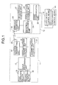
- a portable transmitter 11 carried by a vehicle user can wirelessly transmit a signal for giving an instruction to lock or unlock a door of a vehicle and a signal for giving an instruction to activate an activation device mounted in the vehicle such as a power window mechanism.
- a vehicle-side receiver 12 provided on the vehicle side sends lock-unlock control means 13 and power window control means 14 command signals based on the signals transmitted from the portable transmitter 11. Based on the commands sent from the vehicle-side receiver 12, the lock-unlock control means 13 controls locking or unlocking of the door and the power window control means 14 controls an opening action or closing action of a window.
- the portable transmitter 11 includes: a first operation button 15 which is a manipulator for giving commands to unlock the door and open the window; a second operation button 16 which is a manipulator for giving commands to lock the door and close the window; an input processing unit 17 which processes input signals from the first and second operation buttons 15, 16; a transmitting-side control unit 18 which generates operation information to be transmitted to the vehicle-side receiver 12, on the basis of signals inputted from the input processing unit 17; a wireless transmitting unit 19 which wirelessly transmits signals based on the operation information from the transmitting-side control unit 18, to the vehicle-side receiver 12 via a transmitting antenna 20; and a transmitting-side storage unit 21 which stores operating programs used in the transmitting-side control unit 18, the operation information transmitted in the past, or the like.
- the vehicle-side receiver 12 includes: a wireless receiving unit 23 which receives signals transmitted from the transmitting antenna 20 via a receiving antenna 22; a reception processing unit 24 which recovers the operation information from the signals received by the wireless receiving unit 23; a wired communication unit 25 which performs data communication between the lock-unlock control means 13 and the power window control means 14 through wires; a receiving-side control unit 26 which converts the operation information recovered by the reception processing unit 24 to data transmittable from the wired communication unit 25; and a receiving-side storage unit 27 which stores operating programs used in the receiving-side control unit 26, or the like.
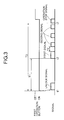
- the portable transmitter 11 transmits the signal to the vehicle-side receiver 12 according to a control procedure shown in FIG. 2 , for example, in response to an on-operation in which the vehicle user presses the first operation button 15 used to give the commands to unlock the door and open the window.
- step S1 an unlock signal is transmitted in response to the on-operation of the first operation button 15 and, in step S2, time measuring by a first timer is started.
- step S3 when the portable transmitter 11 confirms that a first predetermined time T1, for example, one second, has not elapsed from the start of the time measuring by the first timer, the procedure proceeds to step S4 and the portable transmitter 11 confirms whether or not the on-operation of the first operation button 15 is still continuously performed.
- step S4 the procedure returns from step S4 to step S3.
- step S3 the portable transmitter 11 confirms that the on-operation of the first operation button 15 is stopped, the signal transmission to the vehicle-side receiver 12 is stopped.
- step S5 a first signal for causing the window to move to an opening side is transmitted, and in step S6 after the transmission of the first signal, time measuring by a second timer is started.
- step S7 the portable transmitter 11 confirms whether or not the time measured by the second timer has reached a second predetermined time T2, for example, 200 milliseconds.
- the time measuring by the second timer is started again in step S8 and a second signal for causing the window to move to the opening side is transmitted in step S9.
- step S10 the portable transmitter 11 confirms whether or not the time measured by the first timer has reached a third predetermined time T3, for example, 10 seconds.
- a third predetermined time T3 for example, 10 seconds.
- the signal transmission to the vehicle-side receiver 12 is stopped.
- the portable transmitter 11 confirms that the measured time has not reached the third predetermined time T3, the procedure returns from step S10 to step S7.
- step S11 the portable transmitter 11 confirms whether or not the on-operation of the first operation button 15 is still continuously performed.
- the procedure returns from step S11 to step S7.
- step S12 an operation stop signal for stopping the opening action of the window is transmitted and then the signal transmission to the vehicle-side receiver 12 is stopped.
- the portable transmitter 11 first transmits the unlock signal. Then, in a case where the on-operation of the first operation button 15 is continuously performed for the third predetermined time T3 or more, the following operations are performed.
- the first signal for causing the window to move to the opening side is transmitted at a timing t2 at which the first predetermined time T1 has elapsed.
- the second signal for causing the window to move to the opening side is transmitted every time the second predetermined time T2 elapses, until the third predetermined time T3 elapses from the transmission of the unlock signal. Then, the operation stop signal for stopping the opening action of the window is transmitted at a timing t3 at which the third predetermined time T3 has elapsed from the transmission of the unlock signal.
- formats of the unlock signal and the first signal each include a 192-bit synchronization frame, an 8-bit header, and a 96-bit data frame.
- the second signal includes a synchronization frame, a header, and a data frame like the unlock signal and the first signal.
- the synchronization frame of the second signal can be simplified compared to that of the first signal because synchronization by the first signal has been already completed.
- the synchronization frame of the second signal can be made shorter to, for example, 16 bits.
- the headers of the first and second signals are 8 bits like that of the unlock signal.
- the data frames of the unlock signal and the first signal each have at least an ID code, a function code, and a first error detection code.
- the data frames each have a rolling code, the ID code, the function code, an encryption code such as SR or the like, and the first error detection code such as CRC (cyclic redundancy check) or the like.
- the rolling code is a variable code in which, every time the signal is transmitted from the portable transmitter 11, a value is incremented or decremented by "1", for example, for every transmission of the signal, on the basis of a conversion rule determined in advance, and is, for example, 16 bits.
- the ID code is a code for confirming whether or not the portable transmitter 11 has the same ID as that registered in the vehicle, and is, for example, 32 bits.
- the function code of the unlock signal is a code for giving an instruction to unlock the door and the function code of the first signal is a code for giving an instruction to open the window. Both function codes are, for example, 8 bits, respectively.
- the first error detection code is generated by using the rolling code, the ID code, the function code, and the encryption code, and is, for example, 8 bits.
- the data frame of each of the unlock signal and the first signal is thus, for example, 96 bits.
- the data frame of the second signal includes only a function code for giving an instruction to open the window and a second error detection code generated based on the function code, and the data frame of the first signal.
- the second error detection code is generated from the function code and the codes in the data frame of the first signal other than the function code and the first error detection code. Since the data frame of the first signal has the rolling code, the ID code, the function code, the encryption code, and the first error detection code, the second error detection code in the data frame of the second signal is generated from the rolling code, the ID code, and the encryption code in the data frame of the first signal, as well as the function code.
- the second error detection code is, for example, 8 bits.
- control which is performed when the first operation button 15 is operated to give commands to unlock the door and open the window. Meanwhile, the following control is performed when the second operation button 16 is operated to give commands to lock the door and close the window.
- the portable transmitter 11 first transmits a lock signal.
- the portable transmitter 11 transmits a first signal for causing the window to move to a closing side, after the transmission of the lock signal. After the transmission of the first signal, the portable transmitter 11 repeatedly transmits a second signal for causing the window to move to the closing side, and stops the transmission of the second signal when the third predetermined time T3 elapses.
- the portable transmitter 11 transmits the first signal including the data frame having at least the ID code, the function code, for example, for giving the instruction to open or close the window, and the first error detection code, and then repeatedly transmits the second signal including the data frame having only the function code and the second error detection code generated based on the data frame of the first signal. Accordingly, data length of the second signal can be reduced. This can reduce current consumption of the portable transmitter 11 in a case where the first operation button 15 or the second operation button 16 is operated continuously, and thereby suppress reduction of battery life.
- the portable transmitter 11 can transmit the unlock signal for giving the instruction to unlock the door or the lock signal for giving the instruction to lock the door, in response to the operation of the first operation button 15 or the second operation button 16 which is performed for a short time less than the first predetermined time T1.
- the first operation button 15 or the second operation button 16 can have the function of giving the instruction to lock or unlock the door in addition to the function of giving the instruction to activate the activation device such as the power window mechanism.
- Various kinds of remote control can be thus performed by using the portable transmitter 11 with the number of required operation buttons being suppressed to a small number.
Landscapes
- Engineering & Computer Science (AREA)
- Mechanical Engineering (AREA)
- Physics & Mathematics (AREA)
- General Physics & Mathematics (AREA)
- Computer Networks & Wireless Communication (AREA)
- Signal Processing (AREA)
- Lock And Its Accessories (AREA)
- Selective Calling Equipment (AREA)
Abstract


Description
- The present invention relates to a remote control device for a vehicle comprising: a portable transmitter configured to repeatedly transmit a signal for giving an instruction to activate an activation device mounted in a vehicle, in response to an operation of a manipulator which is performed continuously for a predetermined time or more; and a vehicle-side receiver provided in the vehicle to activate the activation device on the basis of the signal transmitted from the portable transmitter.
- Japanese Patent Application Laid-open No.
2004-239002 - Since a signal having a long data length is repeatedly transmitted from the portable transmitter in the pressing and holding of the operation button, a battery of the portable transmitter is consumed rapidly and the battery life is reduced.
- Meanwhile, the following system is known from Japanese Patent Application Laid-open No.
2003-110554 - The present invention has been made in view of the circumstances described above, and an object of at least the preferred embodiments of the invention is to provide a remote control device for a vehicle which can reduce battery consumption of a portable transmitter.
- According to a first aspect of the present invention, there is provided a remote control device for a vehicle comprising: a portable transmitter configured to repeatedly transmit a signal for giving an instruction to activate an activation device mounted in a vehicle, in response to an operation of a manipulator which is performed continuously for a predetermined time or more; and a vehicle-side receiver provided in the vehicle to activate the activation device on the basis of the signal transmitted from the portable transmitter, wherein in response to the continuous operation of the manipulator which is performed to give the instruction to activate the activation device, the portable transmitter transmits a first signal including a data frame having at least an ID code, a function code determining an action of the activation device, and a first error detection code and then repeatedly transmits a second signal, and a data frame of the second signal is set to have only the same function code as the function code of the first signal and a second error detection code, the second error detection code being generated based on said function code and the data frame of the first signal.
- According to a second aspect of the present invention, in addition to the first aspect, the data frame of the first signal has a rolling code, the ID code, the function code, an encryption code, and the first error detection code generated from the rolling code, the ID code, the function code, and the encryption code, and the portable transmitter generates the second error detection code included in the data frame of the second signal, from the function code and the codes in the data frame of the first signal other than the function code and the first error detection code.
- In the aforementioned aspects of the present invention, when the manipulator is operated continuously to give an instruction to activate the activation device, the portable transmitter transmits the first signal including the data frame having at least the ID code, the function code, and the first error detection code and then repeatedly transmits the second signal, and the data frame of the second signal has only the function code and the second error detection code generated based on the function code and the data frame of the first signal. Accordingly, data length of the second signal can be reduced. This can reduce current consumption of the portable transmitter in a case where the manipulator is operated continuously, and thereby suppress reduction of battery life.
- According to a third aspect of the present invention, in addition to the first or second aspect, the portable transmitter is capable of transmitting a signal for giving an instruction to unlock or lock a door, in response to an operation of the manipulator which is performed for a short time less than the predetermined time.
- Particularly in the third aspect, the manipulator can have a function of giving the instruction to lock or unlock the door, in addition to a function to give the instruction to activate the activation device. Various kinds of remote operations can be thus performed by using the portable transmitter with the number of required manipulators being suppressed to a small number.
- The above and other objects, characteristics and advantages of the present invention will be clear from detailed descriptions of the preferred embodiment which will be provided below while referring to the attached drawings.
-
-
FIG. 1 is a view showing an overall configuration of a remote control device. -
FIG. 2 is a flowchart showing a signal transmission control procedure in a portable transmitter. -
FIG. 3 is a timing chart showing a signal transmission state from the portable transmitter in a case where an operation button is operated. -
FIGS. 4A to 4C are views for comparing formats of an unlock signal, a first signal, and a second signal. -
FIGS. 5A to 5C are views in which data frame configurations of the unlock signal, the first signal, and the second signal are compared. - An embodiment of the present invention is described below, by way of example only, with reference to attached
FIGS. 1 to 5C . First, inFIG. 1 , aportable transmitter 11 carried by a vehicle user can wirelessly transmit a signal for giving an instruction to lock or unlock a door of a vehicle and a signal for giving an instruction to activate an activation device mounted in the vehicle such as a power window mechanism. A vehicle-side receiver 12 provided on the vehicle side sends lock-unlock control means 13 and power window control means 14 command signals based on the signals transmitted from theportable transmitter 11. Based on the commands sent from the vehicle-side receiver 12, the lock-unlock control means 13 controls locking or unlocking of the door and the power window control means 14 controls an opening action or closing action of a window. - The
portable transmitter 11 includes: afirst operation button 15 which is a manipulator for giving commands to unlock the door and open the window; asecond operation button 16 which is a manipulator for giving commands to lock the door and close the window; aninput processing unit 17 which processes input signals from the first andsecond operation buttons side control unit 18 which generates operation information to be transmitted to the vehicle-side receiver 12, on the basis of signals inputted from theinput processing unit 17; awireless transmitting unit 19 which wirelessly transmits signals based on the operation information from the transmitting-side control unit 18, to the vehicle-side receiver 12 via a transmittingantenna 20; and a transmitting-side storage unit 21 which stores operating programs used in the transmitting-side control unit 18, the operation information transmitted in the past, or the like. - Moreover, the vehicle-
side receiver 12 includes: awireless receiving unit 23 which receives signals transmitted from the transmittingantenna 20 via a receivingantenna 22; areception processing unit 24 which recovers the operation information from the signals received by thewireless receiving unit 23; awired communication unit 25 which performs data communication between the lock-unlock control means 13 and the power window control means 14 through wires; a receiving-side control unit 26 which converts the operation information recovered by thereception processing unit 24 to data transmittable from thewired communication unit 25; and a receiving-side storage unit 27 which stores operating programs used in the receiving-side control unit 26, or the like. - The
portable transmitter 11 transmits the signal to the vehicle-side receiver 12 according to a control procedure shown inFIG. 2 , for example, in response to an on-operation in which the vehicle user presses thefirst operation button 15 used to give the commands to unlock the door and open the window. In step S1, an unlock signal is transmitted in response to the on-operation of thefirst operation button 15 and, in step S2, time measuring by a first timer is started. In subsequent step S3, when theportable transmitter 11 confirms that a first predetermined time T1, for example, one second, has not elapsed from the start of the time measuring by the first timer, the procedure proceeds to step S4 and theportable transmitter 11 confirms whether or not the on-operation of thefirst operation button 15 is still continuously performed. When theportable transmitter 11 confirms that the on-operation of thefirst operation button 15 is still continuously performed, the procedure returns from step S4 to step S3. When theportable transmitter 11 confirms that the on-operation of thefirst operation button 15 is stopped, the signal transmission to the vehicle-side receiver 12 is stopped. - When the
portable transmitter 11 confirms that the first predetermined time T1 has elapsed from the start of the time measuring by the first timer in step S3, the procedure proceeds from step S3 to step S5. In step S5, a first signal for causing the window to move to an opening side is transmitted, and in step S6 after the transmission of the first signal, time measuring by a second timer is started. In subsequent step S7, theportable transmitter 11 confirms whether or not the time measured by the second timer has reached a second predetermined time T2, for example, 200 milliseconds. When theportable transmitter 11 confirms that the measured time has reached the second predetermined time T2, the time measuring by the second timer is started again in step S8 and a second signal for causing the window to move to the opening side is transmitted in step S9. After the transmission of the second signal, in step S10, theportable transmitter 11 confirms whether or not the time measured by the first timer has reached a third predetermined time T3, for example, 10 seconds. When theportable transmitter 11 confirms that the measured time has reached the third predetermined time T3, the signal transmission to the vehicle-side receiver 12 is stopped. When theportable transmitter 11 confirms that the measured time has not reached the third predetermined time T3, the procedure returns from step S10 to step S7. - Meanwhile, when the
portable transmitter 11 confirms that the time measured by the second timer has not reached the second predetermined time T2 in step S7, the procedure proceeds from step S7 to step S11. In step S11, theportable transmitter 11 confirms whether or not the on-operation of thefirst operation button 15 is still continuously performed. When theportable transmitter 11 confirms that the on-operation of thefirst operation button 15 is still continuously performed, the procedure returns from step S11 to step S7. When theportable transmitter 11 confirms that the on-operation of thefirst operation button 15 is stopped, the procedure proceeds from step S11 to step S12. In step S12, an operation stop signal for stopping the opening action of the window is transmitted and then the signal transmission to the vehicle-side receiver 12 is stopped. - In the control procedure described above, as shown in
FIG. 3 , when the on-operation of thefirst operation button 15 is performed at a timing t1, theportable transmitter 11 first transmits the unlock signal. Then, in a case where the on-operation of thefirst operation button 15 is continuously performed for the third predetermined time T3 or more, the following operations are performed. After the transmission of the unlock signal, the first signal for causing the window to move to the opening side is transmitted at a timing t2 at which the first predetermined time T1 has elapsed. After the transmission of the first signal, the second signal for causing the window to move to the opening side is transmitted every time the second predetermined time T2 elapses, until the third predetermined time T3 elapses from the transmission of the unlock signal. Then, the operation stop signal for stopping the opening action of the window is transmitted at a timing t3 at which the third predetermined time T3 has elapsed from the transmission of the unlock signal. - In
FIGS. 4A to 4C , formats of the unlock signal and the first signal each include a 192-bit synchronization frame, an 8-bit header, and a 96-bit data frame. Meanwhile, the second signal includes a synchronization frame, a header, and a data frame like the unlock signal and the first signal. However, the synchronization frame of the second signal can be simplified compared to that of the first signal because synchronization by the first signal has been already completed. Compared to the synchronization frame of the first signal which is 192 bits, the synchronization frame of the second signal can be made shorter to, for example, 16 bits. Furthermore, the headers of the first and second signals are 8 bits like that of the unlock signal. - The data frames of the unlock signal and the first signal each have at least an ID code, a function code, and a first error detection code. In the embodiment, as shown in
FIGS. 5A and 5B , the data frames each have a rolling code, the ID code, the function code, an encryption code such as SR or the like, and the first error detection code such as CRC (cyclic redundancy check) or the like. - The rolling code is a variable code in which, every time the signal is transmitted from the
portable transmitter 11, a value is incremented or decremented by "1", for example, for every transmission of the signal, on the basis of a conversion rule determined in advance, and is, for example, 16 bits. Moreover, the ID code is a code for confirming whether or not theportable transmitter 11 has the same ID as that registered in the vehicle, and is, for example, 32 bits. The function code of the unlock signal is a code for giving an instruction to unlock the door and the function code of the first signal is a code for giving an instruction to open the window. Both function codes are, for example, 8 bits, respectively. The first error detection code is generated by using the rolling code, the ID code, the function code, and the encryption code, and is, for example, 8 bits. The data frame of each of the unlock signal and the first signal is thus, for example, 96 bits. - Meanwhile, as shown in
FIG. 5C , the data frame of the second signal includes only a function code for giving an instruction to open the window and a second error detection code generated based on the function code, and the data frame of the first signal. In the embodiment, the second error detection code is generated from the function code and the codes in the data frame of the first signal other than the function code and the first error detection code. Since the data frame of the first signal has the rolling code, the ID code, the function code, the encryption code, and the first error detection code, the second error detection code in the data frame of the second signal is generated from the rolling code, the ID code, and the encryption code in the data frame of the first signal, as well as the function code. The second error detection code is, for example, 8 bits. - Description is given above of control which is performed when the
first operation button 15 is operated to give commands to unlock the door and open the window. Meanwhile, the following control is performed when thesecond operation button 16 is operated to give commands to lock the door and close the window. As in the above description, when the on-operation of thesecond operation button 16 is performed, theportable transmitter 11 first transmits a lock signal. When the on-operation of thesecond operation button 16 is performed continuously for the third predetermined time T3 or more, theportable transmitter 11 transmits a first signal for causing the window to move to a closing side, after the transmission of the lock signal. After the transmission of the first signal, theportable transmitter 11 repeatedly transmits a second signal for causing the window to move to the closing side, and stops the transmission of the second signal when the third predetermined time T3 elapses. - Next, operations of the embodiment are described. When, in order to give the instruction to activate the activation device mounted in the vehicle, the
first operation button 15 or thesecond operation button 16 is operated continuously for the first predetermined time T1 or more, theportable transmitter 11 transmits the first signal including the data frame having at least the ID code, the function code, for example, for giving the instruction to open or close the window, and the first error detection code, and then repeatedly transmits the second signal including the data frame having only the function code and the second error detection code generated based on the data frame of the first signal. Accordingly, data length of the second signal can be reduced. This can reduce current consumption of theportable transmitter 11 in a case where thefirst operation button 15 or thesecond operation button 16 is operated continuously, and thereby suppress reduction of battery life. - Moreover, the
portable transmitter 11 can transmit the unlock signal for giving the instruction to unlock the door or the lock signal for giving the instruction to lock the door, in response to the operation of thefirst operation button 15 or thesecond operation button 16 which is performed for a short time less than the first predetermined time T1. Accordingly, thefirst operation button 15 or thesecond operation button 16 can have the function of giving the instruction to lock or unlock the door in addition to the function of giving the instruction to activate the activation device such as the power window mechanism. Various kinds of remote control can be thus performed by using theportable transmitter 11 with the number of required operation buttons being suppressed to a small number. - Although the embodiment of the present invention has been described above, the present invention is not limited to the embodiment and various design changes can be made without departing from the present invention described in the claims.
Claims (3)
- A remote control device for a vehicle comprising:a portable transmitter (11) configured to repeatedly transmit a signal for giving an instruction to activate an activation device mounted in a vehicle, in response to an operation of a manipulator (15, 16) which is performed continuously for a predetermined time or more; anda vehicle-side receiver (12) provided in the vehicle to activate the activation device on the basis of the signal transmitted from the portable transmitter (11), whereinin response to the continuous operation of the manipulator (15, 16) which is performed to give the instruction to activate the activation device, the portable transmitter (11) transmits a first signal including a data frame having at least an ID code, a function code determining an action of the activation device, and a first error detection code and then repeatedly transmits a second signal, anda data frame of the second signal is set to have only the same function code as the function code of the first signal and a second error detection code, the second error detection code being generated based on said function code and the data frame of the first signal.
- The remote control device for a vehicle according to claim 1, wherein
the data frame of the first signal has a rolling code, the ID code, the function code, an encryption code, and the first error detection code generated from the rolling code, the ID code, the function code, and the encryption code, and
the portable transmitter (11) generates the second error detection code included in the data frame of the second signal, from the function code and the codes in the data frame of the first signal other than the function code and the first error detection code. - The remote control device for a vehicle according to claim 1 or 2, wherein the portable transmitter (11) is capable of transmitting a signal for giving an instruction to unlock or lock a door, in response to an operation of the manipulator (15, 16) which is performed for a short time less than the predetermined time.
Applications Claiming Priority (1)
| Application Number | Priority Date | Filing Date | Title |
|---|---|---|---|
| JP2012268054A JP5823945B2 (en) | 2012-12-07 | 2012-12-07 | Vehicle remote control device |
Publications (3)
| Publication Number | Publication Date |
|---|---|
| EP2740637A2 true EP2740637A2 (en) | 2014-06-11 |
| EP2740637A3 EP2740637A3 (en) | 2014-10-29 |
| EP2740637B1 EP2740637B1 (en) | 2016-03-16 |
Family
ID=49911122
Family Applications (1)
| Application Number | Title | Priority Date | Filing Date |
|---|---|---|---|
| EP13196100.5A Active EP2740637B1 (en) | 2012-12-07 | 2013-12-06 | Remote control device for vehicle |
Country Status (4)
| Country | Link |
|---|---|
| US (1) | US9183684B2 (en) |
| EP (1) | EP2740637B1 (en) |
| JP (1) | JP5823945B2 (en) |
| CN (1) | CN103863248B (en) |
Families Citing this family (28)
| Publication number | Priority date | Publication date | Assignee | Title |
|---|---|---|---|---|
| US11352812B2 (en) | 2013-03-15 | 2022-06-07 | August Home, Inc. | Door lock system coupled to an image capture device |
| US9727328B2 (en) * | 2013-03-15 | 2017-08-08 | August Home Inc. | Intelligent door lock system with firmware updates |
| US11527121B2 (en) | 2013-03-15 | 2022-12-13 | August Home, Inc. | Door lock system with contact sensor |
| US11441332B2 (en) | 2013-03-15 | 2022-09-13 | August Home, Inc. | Mesh of cameras communicating with each other to follow a delivery agent within a dwelling |
| US11043055B2 (en) | 2013-03-15 | 2021-06-22 | August Home, Inc. | Door lock system with contact sensor |
| US10443266B2 (en) | 2013-03-15 | 2019-10-15 | August Home, Inc. | Intelligent door lock system with manual operation and push notification |
| US10691953B2 (en) | 2013-03-15 | 2020-06-23 | August Home, Inc. | Door lock system with one or more virtual fences |
| US11802422B2 (en) | 2013-03-15 | 2023-10-31 | August Home, Inc. | Video recording triggered by a smart lock device |
| US11421445B2 (en) | 2013-03-15 | 2022-08-23 | August Home, Inc. | Smart lock device with near field communication |
| US9916746B2 (en) | 2013-03-15 | 2018-03-13 | August Home, Inc. | Security system coupled to a door lock system |
| US10388094B2 (en) | 2013-03-15 | 2019-08-20 | August Home Inc. | Intelligent door lock system with notification to user regarding battery status |
| US11072945B2 (en) | 2013-03-15 | 2021-07-27 | August Home, Inc. | Video recording triggered by a smart lock device |
| US9528296B1 (en) | 2013-03-15 | 2016-12-27 | August Home, Inc. | Off center drive mechanism for thumb turning lock system for intelligent door system |
| US10181232B2 (en) | 2013-03-15 | 2019-01-15 | August Home, Inc. | Wireless access control system and methods for intelligent door lock system |
| US10140828B2 (en) | 2015-06-04 | 2018-11-27 | August Home, Inc. | Intelligent door lock system with camera and motion detector |
| US9704314B2 (en) | 2014-08-13 | 2017-07-11 | August Home, Inc. | BLE/WiFi bridge that detects signal strength of Bluetooth LE devices at an exterior of a dwelling |
| JP6084551B2 (en) * | 2013-11-06 | 2017-02-22 | 株式会社ホンダロック | Outdoor handle device for vehicle door |
| US9725070B2 (en) * | 2014-08-26 | 2017-08-08 | Ford Global Technologies, Llc | Electronic vehicle security system devoid of lock cylinders |
| KR101612829B1 (en) * | 2014-11-27 | 2016-04-15 | 현대자동차주식회사 | Telematics terminal, center for preventing vehicle discharge and control method for preventing vehicle discharge the same |
| JP6706761B2 (en) * | 2015-03-30 | 2020-06-10 | パナソニックIpマネジメント株式会社 | Transmitting device, receiving device, and communication system including these |
| US20170120932A1 (en) * | 2015-11-03 | 2017-05-04 | GM Global Technology Operations LLC | Gesture-based vehicle-user interaction |
| US10269199B2 (en) * | 2017-09-27 | 2019-04-23 | Honda Motor Co., Ltd. | System and method for providing energy efficient hands free vehicle door operation |
| CN111833488B (en) * | 2019-12-31 | 2023-01-06 | 广州骑安科技有限公司 | Lock opening and closing method and device, electronic lock and storage medium |
| US11924811B2 (en) * | 2020-03-04 | 2024-03-05 | Fort Robotics, Inc. | Secure wireless communication of robotic safety state information |
| CN111968272A (en) * | 2020-08-25 | 2020-11-20 | 天津经纬恒润科技有限公司 | Data transmission method and device for remote control access control system |
| EP4214388A4 (en) | 2020-09-17 | 2024-11-06 | Assa Abloy Limited | MAGNETIC SENSOR FOR A LOCK POSITION |
| US12067855B2 (en) | 2020-09-25 | 2024-08-20 | ASSA ABLOY Residential Group, Inc. | Door lock with magnetometers |
| KR20240027751A (en) * | 2021-07-01 | 2024-03-04 | 하만인터내셔날인더스트리스인코포레이티드 | System and method for secure keyless system |
Citations (2)
| Publication number | Priority date | Publication date | Assignee | Title |
|---|---|---|---|---|
| JP2003110554A (en) | 2001-10-01 | 2003-04-11 | Denso Corp | In-vehicle receiver and wireless system for vehicle |
| JP2004239002A (en) | 2003-02-07 | 2004-08-26 | Denso Corp | Communication system for vehicle remote control, transmitting device, and receiving device |
Family Cites Families (30)
| Publication number | Priority date | Publication date | Assignee | Title |
|---|---|---|---|---|
| US4942393A (en) * | 1988-05-27 | 1990-07-17 | Lectron Products, Inc. | Passive keyless entry system |
| JP2912085B2 (en) * | 1992-05-11 | 1999-06-28 | アルプス電気株式会社 | How to send and receive operation signals |
| US5299228A (en) * | 1992-12-28 | 1994-03-29 | Motorola, Inc. | Method and apparatus of reducing power consumption in a CDMA communication unit |
| EP1229672B9 (en) * | 1994-09-21 | 2004-11-17 | Hill-Rom Services, Inc. | Optical data communication and location apparatus |
| JP3284807B2 (en) | 1995-01-20 | 2002-05-20 | 三菱自動車工業株式会社 | Remote control device |
| US5844517A (en) * | 1996-02-02 | 1998-12-01 | Trw Inc. | Portable transceiver for keyless vehicle entry system having phase delay |
| US5838257A (en) * | 1996-05-24 | 1998-11-17 | Trw Inc. | Keyless vehicle entry system employing portable transceiver having low power consumption |
| JPH10131569A (en) * | 1996-11-01 | 1998-05-19 | Nissan Motor Co Ltd | Keyless entry device |
| JP2970638B2 (en) * | 1997-05-16 | 1999-11-02 | トヨタ自動車株式会社 | Mobile device remote control device |
| US6198995B1 (en) * | 1998-03-31 | 2001-03-06 | Lear Automotive Dearborn, Inc. | Sleep mode for vehicle monitoring system |
| US6169492B1 (en) * | 1998-07-29 | 2001-01-02 | Motorola, Inc. | Remote keyless entry user-transparent auto re-synchronization apparatus and method |
| JP4332820B2 (en) * | 1998-11-12 | 2009-09-16 | マツダ株式会社 | Keyless entry system |
| US6597897B2 (en) * | 1998-12-14 | 2003-07-22 | Lear Automotive Dearborn, Inc. | Low power radio frequency transmitter with controllable gain |
| DE19909932C1 (en) | 1999-03-06 | 2000-06-21 | Daimler Chrysler Ag | Electronic security system for specifying authentication in a vehicle locking system has an authentication corrector and security controllers with identifying sensors to transmit test data in an associated detection range. |
| JP4603640B2 (en) | 1999-04-14 | 2010-12-22 | 富士通テン株式会社 | Remote control device and remote control receiving device |
| JP2002037024A (en) * | 2000-07-31 | 2002-02-06 | Tokai Rika Co Ltd | Remote operating device for vehicle |
| JP2003174685A (en) * | 2001-12-05 | 2003-06-20 | Matsushita Electric Ind Co Ltd | Remote control transmitter and transmission system using the same |
| US6724322B2 (en) * | 2001-12-21 | 2004-04-20 | Lear Corporation | Remote system for providing vehicle information to a user |
| US7050947B2 (en) * | 2002-01-04 | 2006-05-23 | Siemens Vdo Automotive Corporation | Remote control communication including secure synchronization |
| JP3821006B2 (en) | 2002-02-15 | 2006-09-13 | 株式会社デンソー | Communication system and receiving apparatus |
| US7551057B2 (en) | 2005-11-04 | 2009-06-23 | Lear Corporation | Remote entry system with increased transmit power and reduced quiescent current |
| US7050775B2 (en) * | 2002-07-11 | 2006-05-23 | Itt Manufacturing Enterprises, Inc. | Method and apparatus for securely enabling a radio communication unit from standby mode |
| JP4390437B2 (en) * | 2002-09-17 | 2009-12-24 | 株式会社デンソー | Remote control device |
| US7209030B2 (en) * | 2004-04-23 | 2007-04-24 | Microchip Technology Inc. | Noise alarm timer function for three-axis low frequency transponder |
| KR100710306B1 (en) * | 2005-01-20 | 2007-04-23 | 엘지전자 주식회사 | Remote control having code format structure and method and apparatus for transmitting / receiving thereof |
| US7387235B2 (en) * | 2005-03-16 | 2008-06-17 | Lear Corporation | Mutual authentication security system with recovery from partial programming |
| US7916040B2 (en) * | 2005-12-19 | 2011-03-29 | Audiovox Corporation | Remote control for home entertainment |
| US20080197986A1 (en) * | 2007-02-15 | 2008-08-21 | Tse Hsing Chen | Method of securing car against theft by incorporating antitheft status LED in remote controller |
| FR2959048B1 (en) | 2010-04-20 | 2012-05-11 | Continental Automotive France | METHODS OF TRANSMITTING AND RECEIVING A RADIO FREQUENCY FRAME IN A REMOTE CONTROL SYSTEM OF A MOTOR VEHICLE |
| CN102129731A (en) * | 2010-12-20 | 2011-07-20 | 重庆集诚汽车电子有限责任公司 | Two-way RKE (Remote Keyless Entry) system of automobile |
-
2012
- 2012-12-07 JP JP2012268054A patent/JP5823945B2/en active Active
-
2013
- 2013-12-02 US US14/093,645 patent/US9183684B2/en active Active
- 2013-12-03 CN CN201310644016.1A patent/CN103863248B/en active Active
- 2013-12-06 EP EP13196100.5A patent/EP2740637B1/en active Active
Patent Citations (2)
| Publication number | Priority date | Publication date | Assignee | Title |
|---|---|---|---|---|
| JP2003110554A (en) | 2001-10-01 | 2003-04-11 | Denso Corp | In-vehicle receiver and wireless system for vehicle |
| JP2004239002A (en) | 2003-02-07 | 2004-08-26 | Denso Corp | Communication system for vehicle remote control, transmitting device, and receiving device |
Also Published As
| Publication number | Publication date |
|---|---|
| US9183684B2 (en) | 2015-11-10 |
| JP5823945B2 (en) | 2015-11-25 |
| CN103863248B (en) | 2016-07-13 |
| JP2014114562A (en) | 2014-06-26 |
| US20140159865A1 (en) | 2014-06-12 |
| EP2740637A3 (en) | 2014-10-29 |
| CN103863248A (en) | 2014-06-18 |
| EP2740637B1 (en) | 2016-03-16 |
Similar Documents
| Publication | Publication Date | Title |
|---|---|---|
| EP2740637B1 (en) | Remote control device for vehicle | |
| CN110574080B (en) | Method for operating an authentication system and authentication system for a vehicle | |
| US9875649B2 (en) | Remote control systems for vehicles | |
| CN104118391B (en) | Telemanipulator system | |
| US12185105B2 (en) | Control device and control method | |
| JP2008106576A (en) | Passive keyless entry system | |
| US8891505B2 (en) | Wireless communication system and communication method for wireless communication system | |
| US20160019734A1 (en) | Hands-free trunk release and vehicle entry | |
| US20210136574A1 (en) | Communication device and system | |
| US20210367937A1 (en) | Control device and control method | |
| EP3555872A1 (en) | Selective transmission of commands associated with a single transceiver channel | |
| CN110944884A (en) | Mobile identification emitter | |
| JP2000261866A (en) | Use of remote device trigger paging or satellite paging | |
| US20230124612A1 (en) | Control device and control method | |
| EP3280152B1 (en) | Transmission device, communication system and remote operation device | |
| WO2014115217A1 (en) | Mobile communication device, and storage medium including program product for mobile communication device | |
| JP2014141804A (en) | Electronic key system | |
| JP2018066130A (en) | Electric lock device and electric lock system | |
| US20150199899A1 (en) | Remote control and communication method for remote control | |
| JP6148026B2 (en) | Electronic key system | |
| JP5468834B2 (en) | Software defined radio communication terminal and software defined radio communication system | |
| JP4612589B2 (en) | Communication control device | |
| JP5116718B2 (en) | Passive keyless entry device | |
| JP6022905B2 (en) | Electronic key system | |
| JPWO2011046088A1 (en) | Wireless communication system, transmission apparatus, reception apparatus, reception method, and transmission method |
Legal Events
| Date | Code | Title | Description |
|---|---|---|---|
| PUAI | Public reference made under article 153(3) epc to a published international application that has entered the european phase |
Free format text: ORIGINAL CODE: 0009012 |
|
| 17P | Request for examination filed |
Effective date: 20131206 |
|
| AK | Designated contracting states |
Kind code of ref document: A2 Designated state(s): AL AT BE BG CH CY CZ DE DK EE ES FI FR GB GR HR HU IE IS IT LI LT LU LV MC MK MT NL NO PL PT RO RS SE SI SK SM TR |
|
| AX | Request for extension of the european patent |
Extension state: BA ME |
|
| PUAL | Search report despatched |
Free format text: ORIGINAL CODE: 0009013 |
|
| AK | Designated contracting states |
Kind code of ref document: A3 Designated state(s): AL AT BE BG CH CY CZ DE DK EE ES FI FR GB GR HR HU IE IS IT LI LT LU LV MC MK MT NL NO PL PT RO RS SE SI SK SM TR |
|
| AX | Request for extension of the european patent |
Extension state: BA ME |
|
| RIC1 | Information provided on ipc code assigned before grant |
Ipc: H04L 1/00 20060101ALI20140924BHEP Ipc: G07C 9/00 20060101ALI20140924BHEP Ipc: B60R 25/24 20130101AFI20140924BHEP |
|
| RBV | Designated contracting states (corrected) |
Designated state(s): AL AT BE BG CH CY CZ DE DK EE ES FI FR GB GR HR HU IE IS IT LI LT LU LV MC MK MT NL NO PL PT RO RS SE SI SK SM TR |
|
| GRAP | Despatch of communication of intention to grant a patent |
Free format text: ORIGINAL CODE: EPIDOSNIGR1 |
|
| INTG | Intention to grant announced |
Effective date: 20151117 |
|
| GRAS | Grant fee paid |
Free format text: ORIGINAL CODE: EPIDOSNIGR3 |
|
| GRAA | (expected) grant |
Free format text: ORIGINAL CODE: 0009210 |
|
| AK | Designated contracting states |
Kind code of ref document: B1 Designated state(s): AL AT BE BG CH CY CZ DE DK EE ES FI FR GB GR HR HU IE IS IT LI LT LU LV MC MK MT NL NO PL PT RO RS SE SI SK SM TR |
|
| REG | Reference to a national code |
Ref country code: GB Ref legal event code: FG4D |
|
| REG | Reference to a national code |
Ref country code: CH Ref legal event code: EP |
|
| REG | Reference to a national code |
Ref country code: IE Ref legal event code: FG4D |
|
| REG | Reference to a national code |
Ref country code: AT Ref legal event code: REF Ref document number: 780920 Country of ref document: AT Kind code of ref document: T Effective date: 20160415 |
|
| REG | Reference to a national code |
Ref country code: DE Ref legal event code: R096 Ref document number: 602013005499 Country of ref document: DE |
|
| REG | Reference to a national code |
Ref country code: NL Ref legal event code: MP Effective date: 20160316 |
|
| REG | Reference to a national code |
Ref country code: LT Ref legal event code: MG4D |
|
| PG25 | Lapsed in a contracting state [announced via postgrant information from national office to epo] |
Ref country code: HR Free format text: LAPSE BECAUSE OF FAILURE TO SUBMIT A TRANSLATION OF THE DESCRIPTION OR TO PAY THE FEE WITHIN THE PRESCRIBED TIME-LIMIT Effective date: 20160316 Ref country code: FI Free format text: LAPSE BECAUSE OF FAILURE TO SUBMIT A TRANSLATION OF THE DESCRIPTION OR TO PAY THE FEE WITHIN THE PRESCRIBED TIME-LIMIT Effective date: 20160316 Ref country code: GR Free format text: LAPSE BECAUSE OF FAILURE TO SUBMIT A TRANSLATION OF THE DESCRIPTION OR TO PAY THE FEE WITHIN THE PRESCRIBED TIME-LIMIT Effective date: 20160617 Ref country code: NO Free format text: LAPSE BECAUSE OF FAILURE TO SUBMIT A TRANSLATION OF THE DESCRIPTION OR TO PAY THE FEE WITHIN THE PRESCRIBED TIME-LIMIT Effective date: 20160616 |
|
| REG | Reference to a national code |
Ref country code: AT Ref legal event code: MK05 Ref document number: 780920 Country of ref document: AT Kind code of ref document: T Effective date: 20160316 |
|
| PG25 | Lapsed in a contracting state [announced via postgrant information from national office to epo] |
Ref country code: LV Free format text: LAPSE BECAUSE OF FAILURE TO SUBMIT A TRANSLATION OF THE DESCRIPTION OR TO PAY THE FEE WITHIN THE PRESCRIBED TIME-LIMIT Effective date: 20160316 Ref country code: LT Free format text: LAPSE BECAUSE OF FAILURE TO SUBMIT A TRANSLATION OF THE DESCRIPTION OR TO PAY THE FEE WITHIN THE PRESCRIBED TIME-LIMIT Effective date: 20160316 Ref country code: SE Free format text: LAPSE BECAUSE OF FAILURE TO SUBMIT A TRANSLATION OF THE DESCRIPTION OR TO PAY THE FEE WITHIN THE PRESCRIBED TIME-LIMIT Effective date: 20160316 Ref country code: NL Free format text: LAPSE BECAUSE OF FAILURE TO SUBMIT A TRANSLATION OF THE DESCRIPTION OR TO PAY THE FEE WITHIN THE PRESCRIBED TIME-LIMIT Effective date: 20160316 Ref country code: RS Free format text: LAPSE BECAUSE OF FAILURE TO SUBMIT A TRANSLATION OF THE DESCRIPTION OR TO PAY THE FEE WITHIN THE PRESCRIBED TIME-LIMIT Effective date: 20160316 |
|
| PG25 | Lapsed in a contracting state [announced via postgrant information from national office to epo] |
Ref country code: EE Free format text: LAPSE BECAUSE OF FAILURE TO SUBMIT A TRANSLATION OF THE DESCRIPTION OR TO PAY THE FEE WITHIN THE PRESCRIBED TIME-LIMIT Effective date: 20160316 Ref country code: IS Free format text: LAPSE BECAUSE OF FAILURE TO SUBMIT A TRANSLATION OF THE DESCRIPTION OR TO PAY THE FEE WITHIN THE PRESCRIBED TIME-LIMIT Effective date: 20160716 Ref country code: PL Free format text: LAPSE BECAUSE OF FAILURE TO SUBMIT A TRANSLATION OF THE DESCRIPTION OR TO PAY THE FEE WITHIN THE PRESCRIBED TIME-LIMIT Effective date: 20160316 |
|
| PG25 | Lapsed in a contracting state [announced via postgrant information from national office to epo] |
Ref country code: SM Free format text: LAPSE BECAUSE OF FAILURE TO SUBMIT A TRANSLATION OF THE DESCRIPTION OR TO PAY THE FEE WITHIN THE PRESCRIBED TIME-LIMIT Effective date: 20160316 Ref country code: RO Free format text: LAPSE BECAUSE OF FAILURE TO SUBMIT A TRANSLATION OF THE DESCRIPTION OR TO PAY THE FEE WITHIN THE PRESCRIBED TIME-LIMIT Effective date: 20160316 Ref country code: CZ Free format text: LAPSE BECAUSE OF FAILURE TO SUBMIT A TRANSLATION OF THE DESCRIPTION OR TO PAY THE FEE WITHIN THE PRESCRIBED TIME-LIMIT Effective date: 20160316 Ref country code: SK Free format text: LAPSE BECAUSE OF FAILURE TO SUBMIT A TRANSLATION OF THE DESCRIPTION OR TO PAY THE FEE WITHIN THE PRESCRIBED TIME-LIMIT Effective date: 20160316 Ref country code: AT Free format text: LAPSE BECAUSE OF FAILURE TO SUBMIT A TRANSLATION OF THE DESCRIPTION OR TO PAY THE FEE WITHIN THE PRESCRIBED TIME-LIMIT Effective date: 20160316 Ref country code: PT Free format text: LAPSE BECAUSE OF FAILURE TO SUBMIT A TRANSLATION OF THE DESCRIPTION OR TO PAY THE FEE WITHIN THE PRESCRIBED TIME-LIMIT Effective date: 20160718 Ref country code: ES Free format text: LAPSE BECAUSE OF FAILURE TO SUBMIT A TRANSLATION OF THE DESCRIPTION OR TO PAY THE FEE WITHIN THE PRESCRIBED TIME-LIMIT Effective date: 20160316 |
|
| REG | Reference to a national code |
Ref country code: DE Ref legal event code: R097 Ref document number: 602013005499 Country of ref document: DE |
|
| PG25 | Lapsed in a contracting state [announced via postgrant information from national office to epo] |
Ref country code: IT Free format text: LAPSE BECAUSE OF FAILURE TO SUBMIT A TRANSLATION OF THE DESCRIPTION OR TO PAY THE FEE WITHIN THE PRESCRIBED TIME-LIMIT Effective date: 20160316 Ref country code: BE Free format text: LAPSE BECAUSE OF FAILURE TO SUBMIT A TRANSLATION OF THE DESCRIPTION OR TO PAY THE FEE WITHIN THE PRESCRIBED TIME-LIMIT Effective date: 20160316 |
|
| PLBE | No opposition filed within time limit |
Free format text: ORIGINAL CODE: 0009261 |
|
| STAA | Information on the status of an ep patent application or granted ep patent |
Free format text: STATUS: NO OPPOSITION FILED WITHIN TIME LIMIT |
|
| PG25 | Lapsed in a contracting state [announced via postgrant information from national office to epo] |
Ref country code: DK Free format text: LAPSE BECAUSE OF FAILURE TO SUBMIT A TRANSLATION OF THE DESCRIPTION OR TO PAY THE FEE WITHIN THE PRESCRIBED TIME-LIMIT Effective date: 20160316 |
|
| 26N | No opposition filed |
Effective date: 20161219 |
|
| PG25 | Lapsed in a contracting state [announced via postgrant information from national office to epo] |
Ref country code: BG Free format text: LAPSE BECAUSE OF FAILURE TO SUBMIT A TRANSLATION OF THE DESCRIPTION OR TO PAY THE FEE WITHIN THE PRESCRIBED TIME-LIMIT Effective date: 20160616 |
|
| PG25 | Lapsed in a contracting state [announced via postgrant information from national office to epo] |
Ref country code: SI Free format text: LAPSE BECAUSE OF FAILURE TO SUBMIT A TRANSLATION OF THE DESCRIPTION OR TO PAY THE FEE WITHIN THE PRESCRIBED TIME-LIMIT Effective date: 20160316 |
|
| REG | Reference to a national code |
Ref country code: CH Ref legal event code: PL |
|
| PG25 | Lapsed in a contracting state [announced via postgrant information from national office to epo] |
Ref country code: MC Free format text: LAPSE BECAUSE OF FAILURE TO SUBMIT A TRANSLATION OF THE DESCRIPTION OR TO PAY THE FEE WITHIN THE PRESCRIBED TIME-LIMIT Effective date: 20160316 |
|
| REG | Reference to a national code |
Ref country code: FR Ref legal event code: ST Effective date: 20170831 |
|
| REG | Reference to a national code |
Ref country code: IE Ref legal event code: MM4A |
|
| PG25 | Lapsed in a contracting state [announced via postgrant information from national office to epo] |
Ref country code: LI Free format text: LAPSE BECAUSE OF NON-PAYMENT OF DUE FEES Effective date: 20161231 Ref country code: FR Free format text: LAPSE BECAUSE OF NON-PAYMENT OF DUE FEES Effective date: 20170102 Ref country code: CH Free format text: LAPSE BECAUSE OF NON-PAYMENT OF DUE FEES Effective date: 20161231 Ref country code: LU Free format text: LAPSE BECAUSE OF NON-PAYMENT OF DUE FEES Effective date: 20161206 |
|
| PG25 | Lapsed in a contracting state [announced via postgrant information from national office to epo] |
Ref country code: IE Free format text: LAPSE BECAUSE OF NON-PAYMENT OF DUE FEES Effective date: 20161206 |
|
| PG25 | Lapsed in a contracting state [announced via postgrant information from national office to epo] |
Ref country code: HU Free format text: LAPSE BECAUSE OF FAILURE TO SUBMIT A TRANSLATION OF THE DESCRIPTION OR TO PAY THE FEE WITHIN THE PRESCRIBED TIME-LIMIT; INVALID AB INITIO Effective date: 20131206 |
|
| PG25 | Lapsed in a contracting state [announced via postgrant information from national office to epo] |
Ref country code: MK Free format text: LAPSE BECAUSE OF FAILURE TO SUBMIT A TRANSLATION OF THE DESCRIPTION OR TO PAY THE FEE WITHIN THE PRESCRIBED TIME-LIMIT Effective date: 20160316 Ref country code: CY Free format text: LAPSE BECAUSE OF FAILURE TO SUBMIT A TRANSLATION OF THE DESCRIPTION OR TO PAY THE FEE WITHIN THE PRESCRIBED TIME-LIMIT Effective date: 20160316 |
|
| GBPC | Gb: european patent ceased through non-payment of renewal fee |
Effective date: 20171206 |
|
| PG25 | Lapsed in a contracting state [announced via postgrant information from national office to epo] |
Ref country code: MT Free format text: LAPSE BECAUSE OF NON-PAYMENT OF DUE FEES Effective date: 20161206 |
|
| PG25 | Lapsed in a contracting state [announced via postgrant information from national office to epo] |
Ref country code: AL Free format text: LAPSE BECAUSE OF FAILURE TO SUBMIT A TRANSLATION OF THE DESCRIPTION OR TO PAY THE FEE WITHIN THE PRESCRIBED TIME-LIMIT Effective date: 20160316 Ref country code: TR Free format text: LAPSE BECAUSE OF FAILURE TO SUBMIT A TRANSLATION OF THE DESCRIPTION OR TO PAY THE FEE WITHIN THE PRESCRIBED TIME-LIMIT Effective date: 20160316 |
|
| PG25 | Lapsed in a contracting state [announced via postgrant information from national office to epo] |
Ref country code: GB Free format text: LAPSE BECAUSE OF NON-PAYMENT OF DUE FEES Effective date: 20171206 |
|
| REG | Reference to a national code |
Ref country code: DE Ref legal event code: R082 Ref document number: 602013005499 Country of ref document: DE |
|
| REG | Reference to a national code |
Ref country code: DE Ref legal event code: R081 Ref document number: 602013005499 Country of ref document: DE Owner name: OMRON AUTOMOTIVE ELECTRONICS CO., LTD., KOMAKI, JP Free format text: FORMER OWNERS: KABUSHIKI KAISHA HONDA LOCK, MIYAZAKI-SHI, MIYAZAKI, JP; OMRON AUTOMOTIVE ELECTRONICS CO., LTD., KOMAKI, AICHI, JP Ref country code: DE Ref legal event code: R081 Ref document number: 602013005499 Country of ref document: DE Owner name: MINEBEA ACCESSSOLUTIONS INC., JP Free format text: FORMER OWNERS: KABUSHIKI KAISHA HONDA LOCK, MIYAZAKI-SHI, MIYAZAKI, JP; OMRON AUTOMOTIVE ELECTRONICS CO., LTD., KOMAKI, AICHI, JP |
|
| PGFP | Annual fee paid to national office [announced via postgrant information from national office to epo] |
Ref country code: DE Payment date: 20251211 Year of fee payment: 13 |