EP2740579B1 - Verfahren zur Herstellung eines Kunststoffbauteils - Google Patents
Verfahren zur Herstellung eines Kunststoffbauteils Download PDFInfo
- Publication number
- EP2740579B1 EP2740579B1 EP13189684.7A EP13189684A EP2740579B1 EP 2740579 B1 EP2740579 B1 EP 2740579B1 EP 13189684 A EP13189684 A EP 13189684A EP 2740579 B1 EP2740579 B1 EP 2740579B1
- Authority
- EP
- European Patent Office
- Prior art keywords
- plastic
- tool
- cavity
- film
- plastic component
- Prior art date
- Legal status (The legal status is an assumption and is not a legal conclusion. Google has not performed a legal analysis and makes no representation as to the accuracy of the status listed.)
- Active
Links
- 239000004033 plastic Substances 0.000 title claims description 133
- 229920003023 plastic Polymers 0.000 title claims description 133
- 238000000034 method Methods 0.000 title claims description 43
- 238000004519 manufacturing process Methods 0.000 title claims description 21
- 238000002347 injection Methods 0.000 claims description 46
- 239000007924 injection Substances 0.000 claims description 46
- 238000005520 cutting process Methods 0.000 claims description 26
- 150000001875 compounds Chemical class 0.000 claims description 20
- 238000001746 injection moulding Methods 0.000 claims description 10
- 238000001816 cooling Methods 0.000 claims description 6
- 239000011248 coating agent Substances 0.000 claims description 4
- 238000000576 coating method Methods 0.000 claims description 4
- 238000004080 punching Methods 0.000 claims description 3
- 230000008569 process Effects 0.000 description 16
- 239000000463 material Substances 0.000 description 13
- 238000003384 imaging method Methods 0.000 description 10
- 239000004922 lacquer Substances 0.000 description 4
- 238000000926 separation method Methods 0.000 description 4
- 239000011888 foil Substances 0.000 description 3
- 239000006223 plastic coating Substances 0.000 description 3
- 230000008901 benefit Effects 0.000 description 2
- 230000008859 change Effects 0.000 description 2
- 238000005034 decoration Methods 0.000 description 2
- 230000002950 deficient Effects 0.000 description 2
- 238000011161 development Methods 0.000 description 2
- 230000018109 developmental process Effects 0.000 description 2
- 238000010586 diagram Methods 0.000 description 2
- 238000005516 engineering process Methods 0.000 description 2
- 239000000155 melt Substances 0.000 description 2
- 238000000465 moulding Methods 0.000 description 2
- 239000003973 paint Substances 0.000 description 2
- 229920000728 polyester Polymers 0.000 description 2
- 230000009467 reduction Effects 0.000 description 2
- 239000002699 waste material Substances 0.000 description 2
- 238000004804 winding Methods 0.000 description 2
- 241001295925 Gegenes Species 0.000 description 1
- XAGFODPZIPBFFR-UHFFFAOYSA-N aluminium Chemical compound [Al] XAGFODPZIPBFFR-UHFFFAOYSA-N 0.000 description 1
- 229910052782 aluminium Inorganic materials 0.000 description 1
- 230000015572 biosynthetic process Effects 0.000 description 1
- 238000011109 contamination Methods 0.000 description 1
- 230000007547 defect Effects 0.000 description 1
- 230000001419 dependent effect Effects 0.000 description 1
- 238000013461 design Methods 0.000 description 1
- 239000000428 dust Substances 0.000 description 1
- 230000008030 elimination Effects 0.000 description 1
- 238000003379 elimination reaction Methods 0.000 description 1
- 238000012423 maintenance Methods 0.000 description 1
- 230000007246 mechanism Effects 0.000 description 1
- 239000000203 mixture Substances 0.000 description 1
- 229920006267 polyester film Polymers 0.000 description 1
- 238000007711 solidification Methods 0.000 description 1
- 230000008023 solidification Effects 0.000 description 1
- 125000006850 spacer group Chemical group 0.000 description 1
- 238000012546 transfer Methods 0.000 description 1
- 238000001721 transfer moulding Methods 0.000 description 1
- 238000011144 upstream manufacturing Methods 0.000 description 1
- 239000002023 wood Substances 0.000 description 1
Images



Classifications
-
- B—PERFORMING OPERATIONS; TRANSPORTING
- B29—WORKING OF PLASTICS; WORKING OF SUBSTANCES IN A PLASTIC STATE IN GENERAL
- B29C—SHAPING OR JOINING OF PLASTICS; SHAPING OF MATERIAL IN A PLASTIC STATE, NOT OTHERWISE PROVIDED FOR; AFTER-TREATMENT OF THE SHAPED PRODUCTS, e.g. REPAIRING
- B29C45/00—Injection moulding, i.e. forcing the required volume of moulding material through a nozzle into a closed mould; Apparatus therefor
- B29C45/14—Injection moulding, i.e. forcing the required volume of moulding material through a nozzle into a closed mould; Apparatus therefor incorporating preformed parts or layers, e.g. injection moulding around inserts or for coating articles
- B29C45/14008—Inserting articles into the mould
- B29C45/14016—Intermittently feeding endless articles, e.g. transfer films, to the mould
-
- B—PERFORMING OPERATIONS; TRANSPORTING
- B29—WORKING OF PLASTICS; WORKING OF SUBSTANCES IN A PLASTIC STATE IN GENERAL
- B29C—SHAPING OR JOINING OF PLASTICS; SHAPING OF MATERIAL IN A PLASTIC STATE, NOT OTHERWISE PROVIDED FOR; AFTER-TREATMENT OF THE SHAPED PRODUCTS, e.g. REPAIRING
- B29C45/00—Injection moulding, i.e. forcing the required volume of moulding material through a nozzle into a closed mould; Apparatus therefor
- B29C45/17—Component parts, details or accessories; Auxiliary operations
- B29C45/40—Removing or ejecting moulded articles
- B29C2045/4094—Ejectors located on the fixed mould half
-
- B—PERFORMING OPERATIONS; TRANSPORTING
- B29—WORKING OF PLASTICS; WORKING OF SUBSTANCES IN A PLASTIC STATE IN GENERAL
- B29C—SHAPING OR JOINING OF PLASTICS; SHAPING OF MATERIAL IN A PLASTIC STATE, NOT OTHERWISE PROVIDED FOR; AFTER-TREATMENT OF THE SHAPED PRODUCTS, e.g. REPAIRING
- B29C45/00—Injection moulding, i.e. forcing the required volume of moulding material through a nozzle into a closed mould; Apparatus therefor
- B29C45/14—Injection moulding, i.e. forcing the required volume of moulding material through a nozzle into a closed mould; Apparatus therefor incorporating preformed parts or layers, e.g. injection moulding around inserts or for coating articles
- B29C45/14008—Inserting articles into the mould
- B29C45/14016—Intermittently feeding endless articles, e.g. transfer films, to the mould
- B29C45/14024—Intermittently feeding endless articles, e.g. transfer films, to the mould and punching or cutting a portion from the endless articles during mould closing
-
- B—PERFORMING OPERATIONS; TRANSPORTING
- B29—WORKING OF PLASTICS; WORKING OF SUBSTANCES IN A PLASTIC STATE IN GENERAL
- B29C—SHAPING OR JOINING OF PLASTICS; SHAPING OF MATERIAL IN A PLASTIC STATE, NOT OTHERWISE PROVIDED FOR; AFTER-TREATMENT OF THE SHAPED PRODUCTS, e.g. REPAIRING
- B29C45/00—Injection moulding, i.e. forcing the required volume of moulding material through a nozzle into a closed mould; Apparatus therefor
- B29C45/14—Injection moulding, i.e. forcing the required volume of moulding material through a nozzle into a closed mould; Apparatus therefor incorporating preformed parts or layers, e.g. injection moulding around inserts or for coating articles
- B29C45/1418—Injection moulding, i.e. forcing the required volume of moulding material through a nozzle into a closed mould; Apparatus therefor incorporating preformed parts or layers, e.g. injection moulding around inserts or for coating articles the inserts being deformed or preformed, e.g. by the injection pressure
- B29C45/14221—Injection moulding, i.e. forcing the required volume of moulding material through a nozzle into a closed mould; Apparatus therefor incorporating preformed parts or layers, e.g. injection moulding around inserts or for coating articles the inserts being deformed or preformed, e.g. by the injection pressure by tools, e.g. cutting means
-
- B—PERFORMING OPERATIONS; TRANSPORTING
- B29—WORKING OF PLASTICS; WORKING OF SUBSTANCES IN A PLASTIC STATE IN GENERAL
- B29C—SHAPING OR JOINING OF PLASTICS; SHAPING OF MATERIAL IN A PLASTIC STATE, NOT OTHERWISE PROVIDED FOR; AFTER-TREATMENT OF THE SHAPED PRODUCTS, e.g. REPAIRING
- B29C45/00—Injection moulding, i.e. forcing the required volume of moulding material through a nozzle into a closed mould; Apparatus therefor
- B29C45/14—Injection moulding, i.e. forcing the required volume of moulding material through a nozzle into a closed mould; Apparatus therefor incorporating preformed parts or layers, e.g. injection moulding around inserts or for coating articles
- B29C45/14336—Coating a portion of the article, e.g. the edge of the article
- B29C45/14344—Moulding in or through a hole in the article, e.g. outsert moulding
-
- B—PERFORMING OPERATIONS; TRANSPORTING
- B29—WORKING OF PLASTICS; WORKING OF SUBSTANCES IN A PLASTIC STATE IN GENERAL
- B29C—SHAPING OR JOINING OF PLASTICS; SHAPING OF MATERIAL IN A PLASTIC STATE, NOT OTHERWISE PROVIDED FOR; AFTER-TREATMENT OF THE SHAPED PRODUCTS, e.g. REPAIRING
- B29C45/00—Injection moulding, i.e. forcing the required volume of moulding material through a nozzle into a closed mould; Apparatus therefor
- B29C45/14—Injection moulding, i.e. forcing the required volume of moulding material through a nozzle into a closed mould; Apparatus therefor incorporating preformed parts or layers, e.g. injection moulding around inserts or for coating articles
- B29C45/14688—Coating articles provided with a decoration
-
- B—PERFORMING OPERATIONS; TRANSPORTING
- B29—WORKING OF PLASTICS; WORKING OF SUBSTANCES IN A PLASTIC STATE IN GENERAL
- B29C—SHAPING OR JOINING OF PLASTICS; SHAPING OF MATERIAL IN A PLASTIC STATE, NOT OTHERWISE PROVIDED FOR; AFTER-TREATMENT OF THE SHAPED PRODUCTS, e.g. REPAIRING
- B29C45/00—Injection moulding, i.e. forcing the required volume of moulding material through a nozzle into a closed mould; Apparatus therefor
- B29C45/14—Injection moulding, i.e. forcing the required volume of moulding material through a nozzle into a closed mould; Apparatus therefor incorporating preformed parts or layers, e.g. injection moulding around inserts or for coating articles
- B29C45/14827—Injection moulding, i.e. forcing the required volume of moulding material through a nozzle into a closed mould; Apparatus therefor incorporating preformed parts or layers, e.g. injection moulding around inserts or for coating articles using a transfer foil detachable from the insert
-
- B—PERFORMING OPERATIONS; TRANSPORTING
- B29—WORKING OF PLASTICS; WORKING OF SUBSTANCES IN A PLASTIC STATE IN GENERAL
- B29C—SHAPING OR JOINING OF PLASTICS; SHAPING OF MATERIAL IN A PLASTIC STATE, NOT OTHERWISE PROVIDED FOR; AFTER-TREATMENT OF THE SHAPED PRODUCTS, e.g. REPAIRING
- B29C45/00—Injection moulding, i.e. forcing the required volume of moulding material through a nozzle into a closed mould; Apparatus therefor
- B29C45/17—Component parts, details or accessories; Auxiliary operations
- B29C45/40—Removing or ejecting moulded articles
-
- B—PERFORMING OPERATIONS; TRANSPORTING
- B29—WORKING OF PLASTICS; WORKING OF SUBSTANCES IN A PLASTIC STATE IN GENERAL
- B29L—INDEXING SCHEME ASSOCIATED WITH SUBCLASS B29C, RELATING TO PARTICULAR ARTICLES
- B29L2031/00—Other particular articles
- B29L2031/30—Vehicles, e.g. ships or aircraft, or body parts thereof
- B29L2031/3055—Cars
-
- B—PERFORMING OPERATIONS; TRANSPORTING
- B29—WORKING OF PLASTICS; WORKING OF SUBSTANCES IN A PLASTIC STATE IN GENERAL
- B29L—INDEXING SCHEME ASSOCIATED WITH SUBCLASS B29C, RELATING TO PARTICULAR ARTICLES
- B29L2031/00—Other particular articles
- B29L2031/722—Decorative or ornamental articles
-
- B—PERFORMING OPERATIONS; TRANSPORTING
- B60—VEHICLES IN GENERAL
- B60R—VEHICLES, VEHICLE FITTINGS, OR VEHICLE PARTS, NOT OTHERWISE PROVIDED FOR
- B60R13/00—Elements for body-finishing, identifying, or decorating; Arrangements or adaptations for advertising purposes
- B60R13/02—Internal Trim mouldings ; Internal Ledges; Wall liners for passenger compartments; Roof liners
Definitions
- the molded parts consist of a support made of plastic, a decorative layer forming the visible surface of the molded part, and an insert of ductile material.
- a material forming the decorative layer and a material forming the insert are inserted and positioned in an opened cavity of an injection molding tool consisting of two tool halves. After closing the two mold halves, a plastic mass forming the carrier is injected through an opening in the insert into the cavity. After solidification and curing, the plastic compound forms together with the material of the decorative layer and the insert from the molding, which can be removed from the injection mold.
- the DE 42 38 131 A1 describes a method for injecting a plastic coating forming a visible surface on a surface of a plastic article, in particular a housing body of a vehicle lamp.
- the molding of the plastic coating on the surface of the plastic article is carried out by injection molding in such a way that no Anspritzmale on the plastic coating are visible on the lying in the later intended use of the article in the field of view of a viewer surface.
- the object is inserted into a mold of an injection mold, wherein the relevant injection channel of the injection mold is brought from the side opposite the surface to be sprayed to an injection opening in the wall of the article and the plastic is injected through this injection opening.
- IMD in-mold decoration
- a wound on a roll designed as a hot stamping foil sheet is passed from top to bottom through an injection mold.
- the hot stamping foil consists of a polyester carrier film and a decorative layer designed as a lacquer layer.
- the injection molding tool has two tool halves that can be moved relative to each other, which form a so-called IMD tool. When closing the mold halves, a film section of the film web is clamped between the mold halves.
- the film section is pressed by the pressure of the melt against the wall of the cavity, and the paint layer of the hot stamping film bonds with the plastic due to the high temperature of the melt. After cooling, the dissolves Lacquer layer of the polyester carrier film.
- the finished decorated component can then be removed from the injection mold or the IMD tool.
- the carrier film is wound on a second roll under the closing unit and a new film section is automatically positioned in front of the cavity.
- the IMD process therefore combines the actual component production and the decoration process of the components in a single operation. It is possible to provide the components with different decors, for example with a paint or a wood or aluminum look. A change of decor is done by means of a roll change.
- the invention has for its object to provide an improved method for producing a plastic component consisting of a plastic body and connected to the plastic body and the visible surface of the plastic component forming decorative coating available.
- a method for producing a plastic component in which the plasticized plastic mass is injected from a side facing away from the decorative layer through an opening in the film section into the cavity arranged between the two mold halves of the injection mold.
- the injection molding nozzle the so-called hot runner nozzle
- the hot runner nozzle can be arranged close to the contour of the plastic component to be produced within the film web, the plastic material in the cavities arranged between the two closed tool halves.
- the injection nozzle both outside the contour of the component to be produced, immediately adjacent to this, but also within the component contour, for example, in an opening of the plastic component can be arranged.
- the hot runner nozzle can be arranged within a clamping frame which fixes the film section to one of the mold halves, so that the cold runner does not have to overcome or pass through it. Due to the small length of the cold runner and a few contour discontinuities, only very small temperature and pressure losses occur during the injection of the plastic mass. As a result, the required process reliability of the process can be ensured.
- the injector for injecting the plastic into the cavity, the slide for the production of plastic components with undercuts and the ejector for removing the finished plastic component from the second mold half provided, which the stationary machine plate of the injection mold is arranged, while the film web and the means for transporting and unwinding or winding the film web of the first, arranged on the movable machine plate mold half are assigned.
- the tool technology can be significantly simplified.
- the ejector and their mechanics in the first, arranged on the movable machine plate mold half is available for the slide or segments and ejector and their mechanics a larger space available so that, for example, the slide and segments can be designed more stable overall ,
- the downtime of the injection mold due to defective slides, segments or ejectors can be minimized and process reliability can be increased.
- the already present in the movable machine plate Gottausnnener can be used to operate the ejector or to actuate the slider, so that can be dispensed with a separate hydraulically driven actuator.
- a particularly expedient development of the method according to the invention is also achieved in that the opening during a closing movement of the open Tool halves is introduced into the film web. This eliminates additional upstream operations for introducing the opening in the film web and it can continue to be used in the conventional, known from the prior art IMD process used film web rolls.
- the opening is introduced into the film section of the film web, which is arranged in the cavity with the mold halves closed.
- the foil section which does not yet have an opening is first of all arranged between the two mold halves and the cavity is closed. During or after closing, an opening is then produced in the film section, through which the plastic compound is then introduced into the cavity immediately thereafter.
- a further feature of the invention is that the opening is introduced by punching in the film section or the film web, wherein a die half of a cutting die and the other tool half is associated with an at least partially immersed in the cutting die cutting punch.
- a die half of a cutting die and the other tool half is associated with an at least partially immersed in the cutting die cutting punch.
- an opening with defined dimensions and clean cut edges can be introduced into the film web or the film section.
- the material of the opening can be completely punched out of the film section, wherein the resulting cut waste must be removed.
- the film web is not cut circumferentially, but the cuts are made partially. In this case, there is no cutting waste, since the opening releasing the opening remains connected to the film section or the film web.
- a particularly simple way to introduce the opening in the film web or the film section is that the opening is made by a mandrel.
- the mandrel is fixed to one of the tool halves.
- the mandrel or the mandrel tip makes contact with the film section and the mandrel tip bores through the film section during the closing movement, thereby bringing the aperture into the film section.
- the production of the opening in the film web is also facilitated by the fact that the film section or the film web is fixed during the introduction of the opening by a hold-down. By fixing the film web is held in a defined position and tensioned so that the aperture process can be safely introduced at the desired position in the film web.
- a non-inventive alternative to the described method according to the invention provides that the opening is introduced into a region of the film web which is adjacent to the film section arranged in the cavity and is arranged outside the cavity.
- an already provided with an opening film section between the two mold halves is arranged in the cavity when closing the mold halves and simultaneously generates an opening in the closing of the two mold halves in an adjacent film section.
- the film web is then further unrolled, so that the film section is available with the opening produced during the previous manufacturing process for the subsequent manufacturing process of the next plastic component.
- a predetermined separation line in particular in the form of holes and / or cuts, is introduced into the film section and that by injecting the plastic mass of the film section along this parting line at least is separated in sections to form the opening.
- the set separation line is generated, for example, by a perforation or by a plurality of intersecting lines arranged at a distance from one another, wherein the set separation line breaks when the plastic mass introduced under pressure breaks.
- a modified alternative embodiment of the method according to the invention which is not modified according to the invention, is also provided in that the aperture is introduced exclusively by the plastic compound which strikes under pressure on the film section arranged in the cavity. In this case, no work or process steps for complete or partial incision and separation of the film web or the film section are required.
- an injection molding tool which consists of at least two mold halves movable between an open and a closed position and a film web extending between the two mold halves and consisting of a carrier layer and a decorative layer, with a film section of the film web between the two tool halves is arranged so that the decorative layer of a negative mold of a visible surface of a plastic component imaging tool surface faces away, wherein an injection nozzle for injecting plastic material is assigned in a formed between the closed mold halves cavity of that mold half, in which the negative mold of the visible surface of the plastic component imaging workpiece surface is integrated, wherein the plastic mass can be injected through an opening in the film section in the cavity is that the plasticized plastic mass pushes the film portion under contact with the decorative layer against the negative surface of the visible surface of the plastic component imaging tool surface.
- the injector injecting the plastic compound into the cavity can be arranged in the stationary machine plate, close to the contour of the plastic component to be produced within the film web. This results in a significant reduction of the cold runner length, which connects the outlet opening with the Anspritzlasche on the component or the sprue of the cavity.
- the injection nozzle can be arranged both outside of the component to be produced, directly next to this, but also inside, for example, in an opening of the component.
- the position of the hot runner nozzle can be arranged within the clamping frame, so that the cold runner does not have to overcome or pass through. Due to the small length of the cold runner and a few contour discontinuities, only very small temperature and pressure losses occur during the injection of the plastic mass.
- the decorative layer facing the tool half may have at least one slide for producing an undercut and / or an ejector for removing the plastic component from the cavity.
- the slides can be designed to be more stable overall, whereby the downtime of the injection mold due to defective slide minimized and process reliability can be increased.
- the means for receiving and for advancing the film web are arranged on the mold half, in which also the injection nozzle and the negative surface of the visible surface of the plastic component imaging tool surface are integrated.
- the arrangement of the film web on the stationary machine plate has the advantage over the arrangement of the film web on the movable machine plate that the film web is exposed to less air movements. This will allow the committee at the Manufacture of plastic components are minimized because they have less resulting from dust or contamination surface defects.
- FIG. 1 shows a perspective view of a produced by the inventive method and designed as a trim part and / or decorative part of a motor vehicle plastic component 1.
- FIG. 2 shows a back view of the in FIG. 1 shown plastic component 1 in a perspective view.
- the plastic component 1 consists of a plastic body 2 and connected to the plastic body 2 and a visible surface 3 of the plastic component 1 forming decorative coating 4, for example, a lacquer layer.
- the plastic component 1 has a plurality of openings 5 and a plurality of projections 6 designed as webs and / or latching elements for positioning and fixing the plastic component 1 on a carrier component of the motor vehicle. In the process, these projections 6 are arranged on a rear side 7 of the plastic component 1 facing away from the visible surface 3.
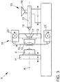
- FIG. 3 shows a schematic diagram of an injection mold 8 for producing the in the Figures 1 and 2
- the injection molding tool 8 has a mold halves 9, 10 existing mold, which in FIG. 3 are shown in an open position.
- the first tool half 9 shown on the left is arranged on a movable machine plate 11, which is displaceable along a schematically indicated axis A, relative to the stationarily arranged machine plate 12.
- the other, in FIG. 3 Right illustrated second mold half 10 is fixed to the stationary machine plate 12.
- the movable machine plate 11 is moved relative to the stationary machine plate 12 with the second mold half 10 together with the first mold half 9.
- a plastic component 1 imaging and in FIG. 3 not shown cavity During or after completion of the closing movement forms between the now together adjacent tool halves 9, 10 a plastic component 1 imaging and in FIG. 3 not shown cavity.
- the injection molding tool 8 has a feed unit 13 for plasticized plastic compound, which comprises a hopper 14, a plasticizing and transporting unit 15 and a nozzle 16.
- the feed unit 13 is also displaceable along the axis A relative to the stationary machine plate 12 to inject through an opening 17 in the stationary machine plate 12 through the plasticized plastic mass in the cavity between the two mold halves 9, 10.
- the injection molding tool 8 has a film feed unit 18 arranged on the stationary machine plate 12, by means of which a film web 19 can be transported from an unwinding unit 20 to a take-up unit 21 (see directional arrows). Both the unwinding unit 20 and the winding unit 21 are formed by corresponding rollers on which the film web 19 is wound. In this case, the film web 19 by a corresponding, in FIG. 3 transport drive, not shown, unwindable from the unwinding unit 20 and windable on the take-up unit 21.
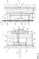
- FIG. 4 shows an enlarged and cut schematic representation of the in FIG. 3 shown and arranged on the machine plates 11, 12 tool halves 9, 10 in the open position.
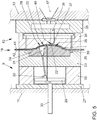
- FIG. 5 shows the tool halves 9, 10 in a closed position, namely after the injection of the plastic material in a closing of the tool halves 9, 10 between these forming cavity 22nd
- the first tool half 9 arranged on the movable machine plate 11 has a core 24 arranged in a core holding plate 23.
- One of the second mold half 10 facing surface 25 of the core 24 limited at closed mold halves 9, 10, the cavity 22 and forms the back 7 of the plastic component 1 from.
- the core holding plate 23 is connected via spacer strips 26 with a clamping plate 27, which in turn is fixed to the movable machine plate 11.
- the first mold half 9 is also assigned an ejector 28 for removing the produced plastic component 1 from the cavity 22 or from the first mold half 9, which is connected via an ejector plate 29 with a central ejector 30 integrated in the movable machine plate 11.
- For producing an undercut on the plastic component 1 or for producing an in FIG. 2 illustrated and having an undercut projection 6 is provided in the first mold half 9 designed as an inclined slide valve 31. It is the Slider 31 mounted on an obliquely executed sliding guide 32 on the ejector plate 29.
- the arranged on the stationary machine plate 12 second mold half 10 has a negative mold of the visible surface 3 of the plastic component 1 imaging tool surface 33 which, together with the surface 25 of the core 24 of the first mold half 9, the cavity 22 between the two closed mold halves 9, 10 limited ,
- the visible surface 3 depicting tool surface 33 is disposed in a mold plate 34 of the second mold half 10.
- the mold plate 34 is connected via an intermediate plate 35 with the stationary machine plate 12.
- the second mold half 10 has a provided for transporting the plasticized plastic mass hot runner 36 which extends from the opening 17 in the stationary machine plate 12 through the intermediate plate 35 and the mold plate 34 through to an opening into the cavity 22 injection nozzle 37.
- the hot runner 36 is associated with a cooling not shown in the figures.
- the decorative layer 42 formed, for example, as a lacquer layer thus faces the first mold half 9 or the core 24 and the carrier layer 41 formed as a polyester film faces the second mold half 10 or the surface 33 (FIG. FIG. 4 ).
- the two tool halves 9, 10 are closed by a movement of the movable machine plate 11 in the direction of the stationary machine plate 12, so that between the two tool halves 9, 10, the plastic component 1 imaging cavity 22 is formed ( FIG. 5 ).
- the plastic compound is introduced via the nozzle 16 of the feed unit 13 into the opening 17 of the stationary machine plate 12 in the hot runner 36 of the second mold half 10.
- the plastic mass passes through the intermediate plate 35 and the mold plate 34 to the injection nozzle 37 and is then injected from this through the opening 40 in the film section 38 into the cavity 22.
- the plasticized plastic mass is injected through the aperture 40 into a space of the cavity 22 formed by the decorative layer 42 and the surface 25 of the core 24 in such a way that the plastic compound contacts the film section 38 against the negative form of the visible surface 3 under contact with the decorative layer 3
- the carrier surface 41 of the film section 38 presses over the complete surface of the mold surface 33 of the cavity 22, which forms the negative mold of the visible surface 3 of the plastic component 1 is applied.
- the plastic body 2 forms from this, which connects with the formation of the plastic component 1 cohesively with the decorative layer 42 of the film section 38.
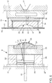
- the two mold halves 9, 10 are opened by a movement of the movable machine plate 11 relative to the stationary machine plate 12 again, so that the tool halves 9, 10 in the in FIG. 6 and the produced plastic component 1 can be removed from the injection mold 8 or from the first mold half 9.
- the carrier layer 41 is peeled off from the decorative layer 42, which is joined to the plastic body 2 by a material fit and forms the visible surface 3 of the plastic component 1.
- the ejector plate 29 is moved by the central ejector 30 of the movable machine plate 11 in the direction of the core 24 and relative thereto, so that the ejector 28 connected to the ejector 29 from the contour of the surface 25th moved out of the core 24 and the plastic component 1 of the core 24 dissolves.
- the ejector plate 29 and the existing for the production of the projection 6 on the plastic component 1 slider 31 is moved relative to the core 24.
- the slide 31 is mounted on the ejector plate 29 via an obliquely formed slide guide 32, the slide 31 moves obliquely upward out of the contour of the surface 25 of the core 24 and thereby simultaneously out of the undercut 43 of the projection 6 of the plastic component 1 ,
- the film web 19 is then unwound by the stationary machine plate 12 associated film feed unit 18 of the unwinding unit 20 and in the direction of in FIG. 6 transported arrow until a in FIG. 7 illustrated subsequent film section 38 'of the film web 19 in the in FIG. 4 shown position between the two tool halves 9, 10 is arranged.
- the film section 38 used in the current process cycle at least in sections, no longer having a decorative layer 42 and only consisting of the carrier layer 41.
- FIG. 6 is wound simultaneously with the unwinding of the film web 19 of the unwinding unit 20 on the take-up unit 21 (see also FIG. 3 ).
- the opening 40 in the film section 38 can according to a non-inventive alternative to the method according to the invention, as in FIG. 7 illustrated, by punching, during the or by the closing movement of the two tool halves 9, 10 are introduced. It shows FIG. 7 , similar to FIG. 5 , the tool halves 9, 10 in the closed position.
- the first mold half 9 has a cutting punch 44 arranged in the core holding plate 23 and the second mold half 10 has a cutting die 45 arranged in the mold plate 34.
- the cutting punch 44 dives into the cutting die 45 and cuts or punches the opening 40 'into the film web 19.
- the opening 40' is thus outside the cavity 22 in the film web 19 and a film section 38 'of the film web 19 introduced, which is used for the subsequent process cycle.
- the film web 19 is further transported, so that the film portion 38 'is arranged with the hole just produced 40' between the two mold halves 9, 10.
- the stroke 46 of the film feed is selected so that the previously punched opening 40 'is located immediately in front of the opening of the injection nozzle 37.
- the production of a plastic component 1 and the production of the opening 40 'for the subsequent process cycle is thus carried out in parallel.
- the cutting punch 44 may also be associated with the second tool half 10 or the cutting die 45 of the first tool half 9.
- FIGS. 8 and 9 each show a section of the arranged in the closed position tool halves 9, 10, wherein the aperture 40 according to the invention in the film section 38 of the film web 19 is introduced, which in closed Tool halves 9, 10 in the cavity 22 and between the surface 25 of the core 24 and the negative mold of the visible surface 3 of the plastic component 1 imaging tool surface 33 is arranged in the mold plate 34.
- the opening 40 is also introduced during or through the closing movement of the tool halves 9, 10 in the film section 38.
- the cutting punch 44 is arranged on the mold plate 34 of the second mold half 10, while the cutting die 45 is integrated in the core 24 of the first mold half 9.
- the cutting punch 44 and the cutting die 45 are each arranged coaxially with the injection nozzle 37 arranged in the second tool half 10.
- the plastic compound is then injected from the injection nozzle 37 through the hollow punch 44 into the cavity 22 or into an injector 37 with the cavity 22 and arranged in the core 24 cold runner 48 is injected.
- hold-down 47 can be arranged for fixing the film section 38 during the introduction of the opening 40 ( FIG. 9 ).
- FIG. 10 shows a modified embodiment of the method according to the invention, according to which the opening 40 is produced in the film section 38 by a mandrel 49 disposed on the core 24, also during or by the closing movement of the two tool halves 9, 10th
- the opening 40 is introduced exclusively by the under high pressure on the film section 38 impinging plastic mass in this.
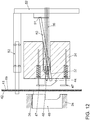
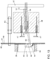
- FIG. 12 and 13 show an embodiment of the method according to the invention, after which the opening 40 is again introduced by a cutting punch 44 and a cutting die 45 in the film section 38.
- the cutting die 45 is associated with the core 24 of the first tool half 9. Trained as an inclined slide punch 44 is mounted on a column 50 and a slide guide 51 on an ejector plate 52 of the second mold half 10. The ejector plate 52 is actuated by a latch train 53. In the cutting punch 44 of the cold runner 48 is integrated.
- FIG. 12 and 13 show an embodiment of the method according to the invention, after which the opening 40 is again introduced by a cutting punch 44 and a cutting die 45 in the film section 38.
- the cutting die 45 is associated with the core 24 of the first tool half 9. Trained as an inclined slide punch 44 is mounted on a column 50 and a slide guide 51 on an ejector plate 52 of the second mold half 10. The ejector plate 52 is actuated by a latch train 53. In the cutting punch 44 of the cold runner 48 is
- FIG. 12 shows an injection position of the oblique slide, in which the cutting punch 44 with the integrated cold runner 48 abuts immediately before the opening of the injector 37 on the mold plate 34 of the second mold half 10, so that the plastic material from the injector 37 via the cold runner 48 into the cavity 22 can pass
- FIG. 13 shows the diagonal slider in the part removal position, wherein the cold channel 48 can be removed from the injection position in the part removal position by the transfer of the inclined slide.
- the plastic mass emerging from the injection nozzle 37 does not come into direct contact with the carrier layer 41 of the film section 38 facing the mold plate 34 by means of such an embodiment. A connection between the plastic compound or the injection nozzle 37 and the carrier layer 41 of the film section 38 can thereby be prevented and prevented process-reliable feed of the film web 19 can be ensured.
- the inventive method can be used for the production of trim parts or decorative parts for the interior area of motor vehicles, such as for shutters for Heilausströmer, switches and surfaces of the radio and the navigation system, light rotary switch, etc.
- the method can also be used for the production of trim and decorative parts in the electrical and consumer electronics, such as covers, switch covers, remote controls, control panels for household appliances, phones and cell phones.
Landscapes
- Engineering & Computer Science (AREA)
- Manufacturing & Machinery (AREA)
- Mechanical Engineering (AREA)
- Injection Moulding Of Plastics Or The Like (AREA)
- Moulds For Moulding Plastics Or The Like (AREA)
Description
- Die Erfindung betrifft ein Verfahren zur Herstellung eines Kunststoffbauteils, insbesondere eines Verkleidungsteils und/oder eines Dekorteils eines Kraftfahrzeugs, bestehend aus einem Kunststoffkörper und einer mit dem Kunststoffkörper verbundenen und die Sichtfläche des Kunststoffbauteils bildenden Dekorbeschichtung, mit folgenden Verfahrensschritten:
- i) Ein aus einer Trägerschicht und einer Dekorschicht bestehender Folienabschnitt wird als Bestandteil einer Folienbahn derart zwischen zwei geöffneten Werkzeughälften eines Spritzgießwerkzeugs angeordnet, dass die Dekorschicht des Folienabschnitts einer eine Negativform der Sichtfläche des Kunststoffbauteils abbildenden Werkzeugoberfläche abgewandt ist;
- ii) erhitzte plastifizierte Kunststoffmasse wird unter Druck derart in eine sich beim Schließen der beiden Werkzeughälften zwischen diesen Werkzeughälften ausbildende Kavität eingespritzt, dass die plastifizierte Kunststoffmasse den Folienabschnitt unter Kontakt mit der Dekorschicht gegen die die Negativform der Sichtfläche des Kunststoffbauteils abbildende Werkzeugoberfläche der Kavität drückt, wobei die Trägerschicht des Folienabschnitts nach Abschluss des Einspritzens der Kunststoffmasse bei einer mit der Kunststoffmasse gefüllten Kavität vollflächig an der die Negativform der Sichtfläche des Kunststoffbauteils abbildenden Werkzeugoberfläche der Kavität anliegt;
- iii) beim Abkühlen der eingespritzten Kunststoffmasse bildet sich aus dieser der Kunststoffkörper aus und verbindet sich unter Bildung des Kunststoffbauteils stoffschlüssig mit der Dekorschicht des Folienabschnitts;
- iv) beim oder nach dem Öffnen der Werkzeughälften wird die Trägerschicht von der stoffschlüssig mit dem Kunststoffkörper verbundenen und die Sichtoberfläche des Kunststoffbauteils bildenden Dekorschicht abgezogen.
- Aus der
DE 10 2007 024 529 A1 ist ein Spritzpressverfahren zur Herstellung von Formteilen, insbesondere von Dekorteilen und Verkleidungsteilen für den Fahrzeuginnenraum bekannt. Die Formteile bestehen aus einem Träger aus Kunststoff, einer die Sichtfläche des Formteils bildenden Dekorschicht und einer Einlage aus duktilem Material. Zur Herstellung des Formteils werden ein die Dekorschicht bildender Werkstoff und ein die Einlage bildendes Material in eine geöffnete Kavität eines aus zwei Werkzeughälften bestehenden Spritzgießwerkzeugs eingelegt und positioniert. Nach dem Schließen der beiden Werkzeughälften wird eine den Träger ausbildende Kunststoffmasse durch eine Durchbrechung in der Einlage hindurch in die Kavität eingespritzt. Nach dem Erstarren und Aushärten bildet die Kunststoffmasse zusammen mit dem Material der Dekorschicht und der Einlage das Formteil aus, welches aus dem Spritzgießwerkzeug entnommen werden kann. - Die
DE 42 38 131 A1 beschreibt ein Verfahren zum Anspritzen eines eine Sichtfläche bildenden Kunststoffüberzugs an eine Oberfläche eines Kunststoffgegenstands, insbesondere eines Gehäusekörpers einer Fahrzeugleuchte. Das Anspritzen des Kunststoffüberzugs an die Oberfläche des Kunststoffgegenstands erfolgt durch Spritzgießen derart, dass an der beim späteren bestimmungsgemäßen Gebrauch des Gegenstands im Sichtbereich eines Betrachters liegenden Oberfläche keine Anspritzmale auf dem Kunststoffüberzug sichtbar sind. Zum Ausführen der Anspritzung ist der Gegenstand in eine Form eines Spritzgießwerkzeugs eingelegt, wobei der betreffende Einspritzkanal des Spritzgießwerkzeugs von der der anzuspritzenden Oberfläche gegenüberliegenden Seite an eine Durchspritzöffnung in der Wand des Gegenstands herangeführt ist und der Kunststoff durch diese Durchspritzöffnung hindurch angespritzt wird. - Ein Verfahren zur Herstellung von als Verkleidungs- oder Dekorteilen ausgebildeten Kunststoffbauteilen der eingangs genannten Art ist in der Praxis als In-Mold-Decoration (IMD) bekannt. Beim IMD-Verfahren wird eine beispielsweise auf einer Rolle aufgewickelte, als Heißprägefolie ausgebildete Folienbahn von oben nach unten durch ein Spritzgießwerkzeug geführt. Die Heißprägefolie besteht dabei aus einer Polyester-Trägerfolie und einer als Lackschicht ausgebildeten Dekorschicht. Das Spritzgießwerkzeug weist zwei relativ zueinander verfahrbare Werkzeughälften auf, welche ein sogenanntes IMD-Werkzeug bilden. Beim Schließen der Werkzeughälften wird ein Folienabschnitt der Folienbahn zwischen den Werkzeughälften eingeklemmt. Beim anschließenden Einspritzen des plastifizierten Kunststoffs bzw. der Kunststoffschmelze wird der Folienabschnitt durch den Druck der Schmelze an die Wand der Kavität gepresst und die Lackschicht der Heißprägefolie verbindet sich durch die hohe Temperatur der Schmelze mit dem Kunststoff. Nach dem Abkühlen löst sich die Lackschicht von der Polyester-Trägerfolie. Das fertig dekorierte Bauteil kann dem Spritzgießwerkzeug bzw. dem IMD-Werkzeug anschließend entnommen werden. Die Trägerfolie wird unter der Schließeinheit auf einer zweiten Rolle aufgewickelt und ein neuer Folienabschnitt wird automatisch vor der Kavität positioniert.
- Beim IMD-Verfahren werden also die eigentliche Bauteilfertigung und der Dekorationsprozess der Bauteile in einem Arbeitsgang zusammengefasst. Dabei ist es möglich, die Bauteile mit unterschiedlichen Dekoren zu versehen, beispielweise mit einer Lackierung oder einer Holz- bzw. Aluminiumoptik. Ein Dekorwechsel wird anhand eines Rollenwechsels vorgenommen.
- Vor diesem Hintergrund liegt der Erfindung die Aufgabe zugrunde, ein verbessertes Verfahren zur Herstellung eines Kunststoffbauteils bestehend aus einem Kunststoffkörper und einer mit dem Kunststoffkörper verbundenen und die Sichtfläche des Kunststoffbauteils bildenden Dekorbeschichtung zur Verfügung zu stellen.
- Die Aufgabe wird gelöst mit einem Verfahren gemäß den Merkmalen des Patentanspruchs 1. Die Unteransprüche 2 bis 4 betreffen besonders zweckmäßige Weiterbildungen der Erfindung.
- Erfindungsgemäß ist also ein Verfahren zur Herstellung eines Kunststoffbauteils vorgesehen, bei welchem die plastifizierte Kunststoffmasse von einer der Dekorschicht abgewandten Seite durch eine Durchbrechung in dem Folienabschnitt hindurch in die zwischen den beiden Werkzeughälften des Spritzgießwerkzeugs angeordnete Kavität eingespritzt wird. Hierdurch kann die die Kunststoffmasse in die zwischen den beiden geschlossenen Werkzeughälften angeordnet Kavitäte einspritzende Einspritzdüse, die sogenannte Heißkanaldüse, nahe der Kontur des herzustellenden Kunststoffbauteils innerhalb der Folienbahn angeordnet werden. Hierdurch ergibt sich eine erhebliche Reduzierung der Kaltkanallänge, welche die Austrittsöffnung der Einspritzdüse bzw. Heißkanaldüse mit der Anspritzlasche am Bauteil bzw. dem Anguss der Kavität verbindet. Dabei kann die Einspritzdüse sowohl außerhalb der Kontur des herzustellenden Bauteils, unmittelbar neben dieser, aber auch innerhalb der Bauteilkontur, beispielsweise in einer Durchbrechung des Kunststoffbauteils, angeordnet werden. Außerdem kann die Heißkanaldüse innerhalb eines den Folienabschnitt an einer der Werkzeughälften fixierenden Klemmrahmens angeordnet werden, sodass der Kaltkanal diesen nicht überwinden bzw. passieren muss. Durch die geringe Kaltkanallänge und wenige Konturversprünge ergeben sich nur sehr geringe Temperatur- und Druckverluste beim Einspritzen der Kunststoffmasse. Hierdurch kann die erforderliche Prozesssicherheit des Verfahrens gewährleistet werden.
- Üblicherweise sind bei den aus dem Stand der Technik bekannten Spritzgießwerkzeugen bzw. IMD-Werkzeugen die Einspritzdüse zum Einspritzen des Kunststoffs in die Kavität, die Schieber zur Herstellung von Kunststoffbauteilen mit Hinterschneidungen und der Auswerfer zur Entfernung des fertigen Kunststoffbauteils aus der zweiten Werkzeughälfte vorgesehen, welche an der ortsfesten Maschinenplatte des Spritzgießwerkzeugs angeordnet ist, während die Folienbahn und die Einrichtungen zum Transport und zum Abwickeln bzw. Aufwickeln der Folienbahn der ersten, an der beweglichen Maschinenplatte angeordneten Werkzeughälfte zugeordnet sind. Durch das erfindungsgemäße Verfahren ist es nunmehr erstmals möglich, dass der Schieber und der Auswerfer sowie deren Mechanik der ersten Werkzeughälfte bzw. der beweglichen Maschinenplatte zugeordnet werden können und die Einspritzdüse sowie die Folienbahn mit den Einrichtungen zum Transport der zweiten Werkzeughälfte bzw. der ortsfesten Maschinenplatte zugeordnet werden können.
- Hierdurch kann die Werkzeugtechnik wesentlich vereinfacht werden. Durch den Wechsel des Schiebers, des Auswerfers und deren Mechanik in die erste, an der beweglichen Maschinenplatte angeordnete Werkzeughälfte steht für die Schieber bzw. Segmente und Auswerfer sowie deren Mechanik ein größerer Bauraum zur Verfügung, sodass beispielsweise die Schieber und Segmente insgesamt stabiler ausgelegt werden können. Hierdurch können die Stillstandzeiten des Spritzgießwerkzeugs aufgrund von defekten Schiebern, Segmenten oder Auswerfern minimiert und die Prozesssicherheit erhöht werden. Außerdem kann der in der beweglichen Maschinenplatte ohnehin vorhandene Zentralausstoßer zur Betätigung des Auswerfers bzw. zur Betätigung des Schiebers verwendet werden, sodass auf eine separate hydraulisch angetriebene Betätigungseinrichtung verzichtet werden kann. Hiermit verbunden ist ein Entfall von Hydraulikzylindern, Schläuchen, Rohren, Anschlüssen sowie deren Steuerung, wodurch sich neben der Vereinfachung der Werkzeugtechnik auch eine Kostenersparnis ergibt. Weiterhin steht auch in der zweiten Werkzeughälfte, welche der festen Maschinenplatte zugeordnet ist, ein größerer Bauraum zur Kühlung der Einspritzdüse zur Verfügung. Durch den zur Verfügung stehenden Bauraum ist es außerdem möglich, die Anzahl an Einspritzdüsen zu erhöhen, wodurch die Prozesssicherheit des Verfahrens ebenfalls erhöht wird. Zusätzlich ergeben sich durch eine derartige Aufteilung der Komponenten auf die beiden Werkzeughälften Vorteile bei der Wartung, da nur die Werkzeughälfte mit den beweglichen Elementen wie Auswerfer, Schieber und Segmente gewartet werden muss. Die Werkzeughälfte mit der Einspritzdüse bleibt davon unberührt.
- Eine besonders zweckmäßige Weiterbildung des erfindungsgemäßen Verfahrens wird auch dadurch erreicht, dass die Durchbrechung während einer Schließbewegung der geöffneten Werkzeughälften in die Folienbahn eingebracht wird. Hierdurch entfallen zusätzliche vorgelagerte Arbeitsschritte zum Einbringen der Durchbrechung in die Folienbahn und es können weiterhin die bei dem herkömmlichen, aus dem Stand der Technik bekannten IMD-Verfahren eingesetzten Folienbahn-Rollen verwendet werden.
- In diesem Fall erweist es sich als vorteilhaft, wenn die Durchbrechung in den Folienabschnitt der Folienbahn eingebracht wird, welcher bei geschlossenen Werkzeughälften in der Kavität angeordnet ist. Dabei wird zunächst der noch keine Durchbrechung aufweisende Folienabschnitt zwischen den beiden Werkzeughälften angeordnet und die Kavität geschlossen. Bei oder nach dem Schließen wird dann eine Durchbrechung in dem Folienabschnitt erzeugt, durch welche dann unmittelbar im Anschluss die Kunststoffmasse in die Kavität eingefüllt wird.
- Ein weiteres erfindungsgemäßes Merkmal besteht darin, dass die Durchbrechung durch Stanzen in den Folienabschnitt oder die Folienbahn eingebracht wird, wobei einer Werkzeughälfte eine Schneidmatrize und der anderen Werkzeughälfte ein zumindest teilweise in die Schneidmatrize eintauchender Schneidstempel zugeordnet ist. Hierdurch lässt sich eine Durchbrechung mit definierten Abmessungen und sauberen Schnittkanten in die Folienbahn bzw. den Folienabschnitt einbringen. Dabei kann das Material der Durchbrechung vollständig aus dem Folienabschnitt ausgestanzt werden, wobei der dabei entstehende Schnittabfall abgeführt werden muss. Alternativ ist es möglich, die Durchbrechung nur teilweise in die Folienbahn einzubringen. Hierbei wird die Folienbahn nicht umlaufend eingeschnitten, sondern die Einschnitte erfolgen partiell. Hierbei entsteht kein Schnittabfall, da der die Durchbrechung freigebende Abschnitt mit dem Folienabschnitt bzw. der Folienbahn verbunden bleibt.
- Eine besonders einfache Möglichkeit, die Durchbrechung in die Folienbahn bzw. den Folienabschnitt einzubringen, besteht darin, dass die Durchbrechung durch einen Dorn hergestellt wird. Hierbei wird der Dorn an einer der Werkzeughälften fixiert. Beim Schließen der beiden Werkzeughälften kommt es zu einem Kontakt des Dorns bzw. der Dornspitze mit dem Folienabschnitt und die Dornspitze bohrt sich während der Schließbewegung durch den Folienabschnitt hindurch und bringt dabei die Durchbrechung in den Folienabschnitt ein.
- Die Herstellung der Durchbrechung in der Folienbahn wird auch dadurch erleichtert, dass der Folienabschnitt oder die Folienbahn während des Einbringens der Durchbrechung durch einen Niederhalter fixiert wird. Durch die Fixierung wird die Folienbahn in einer definierten Lage gehalten und gespannt, sodass die Durchbrechung prozesssicher an der gewünschten Position in die Folienbahn eingebracht werden kann.
- Eine nicht erfindungsgemäße Alternative zum beschriebenen erfindungsgemäßen Verfahren sieht vor, dass die Durchbrechung in einen dem in der Kavität angeordneten Folienabschnitt benachbarten und außerhalb der Kavität angeordneten Bereich der Folienbahn eingebracht wird. Dabei wird beim Schließen der Werkzeughälften ein bereits mit einer Durchbrechung versehener Folienabschnitt zwischen den beiden Werkzeughälften in der Kavität angeordnet und zeitgleich beim Schließen der beiden Werkzeughälften in einem benachbarten Folienabschnitt eine Durchbrechung erzeugt. Nach dem Einspritzen der Kunststoffmasse in die Kavität und der Entnahme des fertigen Kunststoffbauteils aus dem Spritzgießwerkzeug wird dann die Folienbahn weiter abgerollt, sodass der Folienabschnitt mit der während des vorangegangenen Herstellungsprozesses hergestellten Durchbrechung für den nachfolgenden Herstellungsprozess des nächsten Kunststoffbauteils zur Verfügung steht.
- Eine weitere nicht erfindungsgemäße Alternative zum offenbarten erfindungsgemäßen Verfahren zeichnet sich dadurch aus, dass im Bereich der Durchbrechung eine Solltrennlinie, insbesondere in Form von Löchern und/oder Einschnitten, in den Folienabschnitt eingebracht wird und dass durch das Einspritzen der Kunststoffmasse der Folienabschnitt entlang dieser Trennlinie zumindest abschnittsweise unter Bildung der Durchbrechung getrennt wird. Hierbei wird die Solltrennlinie beispielsweise durch eine Perforation oder durch mehrere in einem Abstand zueinander angeordnete Schnittlinien erzeugt, wobei die Solltrennlinie beim Auftreffen der unter Druck eingebrachten Kunststoffmasse reißt.
- Eine wiederum abgewandelte zweckmäßige nicht erfindungsgemäße Alternative zum genannten erfindungsgemäßen Verfahren wird auch dadurch geschaffen, dass die Durchbrechung ausschließlich durch die unter Druck auf den in der Kavität angeordneten Folienabschnitt treffende Kunststoffmasse eingebracht wird. In diesem Fall sind keine Arbeits- bzw. Verfahrensschritte zum vollständigen oder partiellen Einschneiden und Trennen der Folienbahn bzw. des Folienabschnitts erforderlich.
- Zur Durchführung des erfindungsgemäßen Verfahrens ist ein Spritzgießwerkzeug vorgesehen, welches aus zumindest zwei zwischen einer geöffneten und einer geschlossenen Stellung relativ zueinander verfahrbaren Werkzeughälften und einer zwischen den beiden Werkzeughälften hindurchziehbaren und aus einer Trägerschicht und einer Dekorschicht bestehenden Folienbahn besteht, wobei ein Folienabschnitt der Folienbahn derart zwischen den beiden Werkzeughälften angeordnet ist, dass die Dekorschicht einer eine Negativform einer Sichtfläche eines Kunststoffbauteils abbildenden Werkzeugoberfläche abgewandt ist, wobei eine Einspritzdüse zum Einspritzen von Kunststoffmasse in eine sich zwischen den geschlossenen Werkzeughälften ausbildende Kavität derjenigen Werkzeughälfte zugeordnet ist, in welcher auch die die Negativform der Sichtfläche des Kunststoffbauteils abbildende Werkstückoberfläche integriert ist, wobei die Kunststoffmasse durch eine Durchbrechung in dem Folienabschnitt derart in die Kavität einspritzbar ist, dass die plastifizierte Kunststoffmasse den Folienabschnitt unter Kontakt mit der Dekorschicht gegen die die Negativform der Sichtfläche des Kunststoffbauteils abbildende Werkzeugoberfläche drückt.
- Hierdurch wird gewährleistet, dass die die Kunststoffmasse in die Kavität einspritzende Einspritzdüse in der ortsfesten Maschinenplatte, nahe der Kontur des herzustellenden Kunststoffbauteils innerhalb der Folienbahn angeordnet werden kann. Hieraus resultiert eine erhebliche Reduzierung der Kaltkanallänge, welche die Austrittsöffnung mit der Anspritzlasche am Bauteil bzw. dem Anguss der Kavität verbindet. Dabei kann die Einspritzdüse sowohl außerhalb des herzustellenden Bauteils, unmittelbar neben diesem, aber auch innerhalb, beispielsweise in einer Durchbrechung des Bauteils angeordnet werden. Außerdem kann die Position der Heißkanaldüse innerhalb des Klemmrahmens angeordnet werden, sodass der Kaltkanal diesen nicht überwinden bzw. passieren muss. Durch die geringe Kaltkanallänge und wenige Konturversprünge ergeben sich nur sehr geringe Temperatur- und Druckverluste beim Einspritzen der Kunststoffmasse.
- Außerdem kann die der Dekorschicht zugewandte Werkzeughälfte zumindest einen Schieber zur Herstellung einer Hinterschneidung und/oder einen Auswerfer zur Entfernung des Kunststoffbauteils aus der Kavität aufweisen. Durch die Anordnung der zur Erzeugung von Kunststoffbauteilen mit einer Hinterschneidung erforderlichen Schieber in der ersten, an der beweglichen Maschinenplatte angeordneten Werkzeughälfte wird ein größerer Bauraum für die Mechanik und Auslegung der Schieber und Segmente zur Verfügung gestellt. Die Schieber können insgesamt stabiler ausgelegt werden, wodurch die Stillstandzeiten des Spritzgießwerkzeugs aufgrund defekter Schieber minimiert und die Prozesssicherheit gesteigert werden.
- Weiterhin kann vorgesehen sein, dass die Einrichtungen zur Aufnahme und zum Vorschub der Folienbahn an der Werkzeughälfte angeordnet sind, in welcher auch die Einspritzdüse und die die Negativform der Sichtfläche des Kunststoffbauteils abbildende Werkzeugoberfläche integriert sind. Die Anordnung der Folienbahn an der ortsfesten Maschinenplatte hat gegenüber der Anordnung der Folienbahn an der beweglichen Maschinenplatte den Vorteil, dass die Folienbahn weniger Luftbewegungen ausgesetzt ist. Hierdurch kann der Ausschuss bei der Herstellung der Kunststoffbauteile minimiert werden, da diese weniger aus Staub oder Verunreinigungen resultierende Oberflächenfehler aufweisen.
- Nachfolgend werden verschiedene Verfahren zur Herstellung eines Kunststoffbauteils anhand der
Figuren 1 bis 13 beschrieben. Diese zeigen in - Fig. 1
- eine perspektivische Darstellung eines mittels des erfindungsgemäßen Verfahrens hergestellten Kunststoffbauteils;
- Fig. 2
- eine rückseitige Ansicht des in
Figur 1 dargestellten Kunststoffbauteils; - Fig. 3
- eine Prinzipskizze eines Spritzgießwerkzeugs zur Herstellung des in den
Figuren 1 und 2 dargestellten Kunststoffbauteils; - Fig. 4
- eine vergrößerte und geschnittene Prinzipdarstellung der beiden in der geöffneten Stellung angeordneten Werkzeughälften des in
Figur 3 dargestellten Spritzgießwerkzeugs; - Fig. 5
- die in
Figur 4 dargestellten Werkzeughälften in einer geschlossenen Stellung nach dem Einspritzen der Kunststoffmasse; - Fig. 6
- die in der geöffneten Stellung angeordneten Werkzeughälften mit dem hergestellten Kunststoffbauteil;
- Fig. 7
- die in der geschlossenen Stellung angeordneten Werkzeughälften mit einer Schneidmatrize und einem Schneidstempel zum Einbringen einer Durchbrechung in die Folienbahn;
- Fig. 8
- einen Ausschnitt der in der geschlossenen Stellung angeordneten Werkzeughälften mit einem Schneidstempel und einer Schneidmatrize zum Einbringen der Durchbrechung in den Folienabschnitt;
- Fig. 9
- den in
Figur 8 dargestellten Ausschnitt der in der geschlossenen Stellung angeordneten Werkzeughälften mit zwei Niederhaltern; - Fig. 10
- einen Ausschnitt der in der geschlossenen Stellung angeordneten Werkzeughälften mit einem Dorn zum Einbringen der Durchbrechung in den Folienabschnitt;
- Fig. 11
- einen Ausschnitt der in der geschlossenen Stellung angeordneten Werkzeughälften, wobei die Durchbrechung ausschließlich durch die Kunststoffmasse in den Folienabschnitt eingebracht wird;
- Fig. 12
- einen Ausschnitt der beiden Werkzeughälften mit einem in einer ersten Stellung angeordneten Schrägschieber;
- Fig. 13
- den Ausschnitt aus
Figur 12 mit dem in der Teilentnahmeposition angeordneten Schrägschieber. -
Figur 1 zeigt eine perspektivische Darstellung eines mittels des erfindungsgemäßen Verfahrens hergestellten und als Verkleidungsteil und/oder Dekorteil eines Kraftfahrzeugs ausgebildeten Kunststoffbauteils 1. In beispielhafter Ausführung wird hier eine Blende für den Fahrzeuginnenraum beschrieben.Figur 2 zeigt eine rückseitige Ansicht des inFigur 1 dargestellten Kunststoffbauteils 1 in einer perspektivischen Darstellung. Das Kunststoffbauteil 1 besteht aus einem Kunststoffkörper 2 und einer mit dem Kunststoffkörper 2 verbundenen und eine Sichtfläche 3 des Kunststoffbauteils 1 bildenden Dekorbeschichtung 4, beispielsweise einer Lackschicht. Das Kunststoffbauteil 1 weist mehrere Öffnungen 5 und mehrere als Stege und/oder Rastelemente ausgebildete Vorsprünge 6 zur Positionierung und Fixierung des Kunststoffbauteils 1 an einem Trägerbauteil des Kraftfahrzeugs auf. Dabei sind diese Vorsprünge 6 auf einer der Sichtfläche 3 abgewandten Rückseite 7 des Kunststoffbauteils 1 angeordnet. -
Figur 3 zeigt eine Prinzipskizze eines Spritzgießwerkzeugs 8 zur Herstellung des in denFiguren 1 und 2 dargestellten Kunststoffbauteils 1. Das Spritzgießwerkzeug 8 weist ein aus zwei Werkzeughälften 9, 10 bestehendes Formwerkzeug auf, welche inFigur 3 in einer geöffneten Stellung dargestellt sind. Die inFigur 3 links dargestellte erste Werkzeughälfte 9 ist an einer beweglichen Maschinenplatte 11 angeordnet, welche längs einer schematisch angedeuteten Achse A verschiebbar ist, und zwar relativ zu der ortsfest angeordneten Maschinenplatte 12. Die andere, inFigur 3 rechts dargestellte zweite Werkzeughälfte 10 ist an der ortsfesten Maschinenplatte 12 fixiert. Zum Schließen der beiden Werkzeughälften 9, 10 wird die bewegliche Maschinenplatte 11 zusammen mit der ersten Werkzeughälfte 9 relativ zu der ortsfesten Maschinenplatte 12 mit der zweiten Werkzeughälfte 10 verfahren. Während bzw. nach Abschluss der Schließbewegung bildet sich zwischen den nunmehr aneinander anliegenden Werkzeughälften 9, 10 eine das Kunststoffbauteil 1 abbildende und inFigur 3 nicht dargestellte Kavität aus. - Außerdem weist das Spritzgießwerkzeug 8 eine Zuführeinheit 13 für plastifizierte Kunststoffmasse auf, welche einen Trichter 14, eine Plastifizier- und Transporteinheit 15 sowie eine Düse 16 umfasst. Die Zuführeinheit 13 ist ebenfalls entlang der Achse A relativ zu der ortsfesten Maschinenplatte 12 verschiebbar, um durch eine Öffnung 17 in der ortsfesten Maschinenplatte 12 hindurch die plastifizierte Kunststoffmasse in die Kavität zwischen den beiden Werkzeughälften 9, 10 einzuspritzen.
- Weiterhin weist das Spritzgießwerkzeug 8 eine an der ortsfesten Maschinenplatte 12 angeordnete Folienvorschubeinheit 18 auf, mittels welcher eine Folienbahn 19 von einer Abwickeleinheit 20 zu einer Aufwickeleinheit 21 transportierbar ist (siehe Richtungspfeile). Sowohl die Abwickeleinheit 20 als auch die Aufwickeleinheit 21 sind durch entsprechende Rollen gebildet, auf welchen die Folienbahn 19 aufgewickelt ist. Dabei ist die Folienbahn 19 durch einen entsprechenden, in
Figur 3 nicht dargestellten Transportantrieb von der Abwickeleinheit 20 abwickelbar und auf die Aufwickeleinheit 21 aufwickelbar. -
Figur 4 zeigt eine vergrößerte und geschnittene Prinzipdarstellung der inFigur 3 dargestellten und an den Maschinenplatten 11, 12 angeordneten Werkzeughälften 9, 10 in der geöffneten Stellung. Dagegen zeigtFigur 5 die Werkzeughälften 9, 10 in einer geschlossenen Stellung, und zwar nach dem Einspritzen der Kunststoffmasse in eine sich beim Schließen der Werkzeughälften 9, 10 zwischen diesen ausbildende Kavität 22. - Die an der beweglichen Maschinenplatte 11 angeordnete erste Werkzeughälfte 9 weist einen in einer Kernhalteplatte 23 angeordneten Kern 24 auf. Eine der zweiten Werkzeughälfte 10 zugewandte Oberfläche 25 des Kerns 24 begrenzt bei geschlossenen Werkzeughälften 9, 10 die Kavität 22 und bildet die Rückseite 7 des Kunststoffbauteils 1 ab. Die Kernhalteplatte 23 ist über Distanzleisten 26 mit einer Aufspannplatte 27 verbunden, welche wiederum an der beweglichen Maschinenplatte 11 fixiert ist. Der ersten Werkzeughälfte 9 ist außerdem noch ein Auswerfer 28 zur Entfernung des hergestellten Kunststoffbauteils 1 aus der Kavität 22 bzw. aus der ersten Werkzeughälfte 9 zugeordnet, welcher über eine Auswerferplatte 29 mit einem in der beweglichen Maschinenplatte 11 integrierten Zentralausstoßer 30 verbunden ist. Zur Herstellung einer Hinterschneidung an dem Kunststoffbauteil 1 bzw. zur Herstellung eines in
Figur 2 dargestellten und eine Hinterschneidung aufweisenden Vorsprungs 6 ist in der ersten Werkzeughälfte 9 ein als Schrägschieber ausgebildeter Schieber 31 vorgesehen. Dabei ist der Schieber 31 über eine schräg ausgeführte Schiebeführung 32 an der Auswerferplatte 29 gelagert. - Die an der ortsfesten Maschinenplatte 12 angeordnete zweite Werkzeughälfte 10 weist eine die Negativform der Sichtfläche 3 des Kunststoffbauteils 1 abbildende Werkzeugoberfläche 33 auf, welche zusammen mit der Oberfläche 25 des Kerns 24 der ersten Werkzeughälfte 9 die Kavität 22 zwischen den beiden geschlossenen Werkzeughälften 9, 10 begrenzt. Die die Sichtfläche 3 abbildende Werkzeugoberfläche 33 ist in einer Formplatte 34 der zweiten Werkzeughälfte 10 angeordnet. Die Formplatte 34 ist über eine Zwischenplatte 35 mit der ortsfesten Maschinenplatte 12 verbunden. Außerdem weist die zweite Werkzeughälfte 10 einen zum Transport der plastifizierten Kunststoffmasse vorgesehenen Heißkanal 36 auf, welcher sich von der Öffnung 17 in der ortsfesten Maschinenplatte 12 durch die Zwischenplatte 35 und die Formplatte 34 hindurch bis zu einer in die Kavität 22 mündenden Einspritzdüse 37 erstreckt. Dem Heißkanal 36 ist eine in den Figuren nicht dargestellte Kühlung zugeordnet. Zur Fixierung eines zwischen der Werkzeugoberfläche 33 der zweiten Werkzeughälfte 10 und der Oberfläche 25 des Kerns 24 der ersten Werkzeughälfte 9 angeordneten Folienabschnitts 38 der Folienbahn 19 ist ein beweglich in der zweiten Werkzeughälfte 10 gelagerter Klemmrahmen 39 vorgesehen.
- Die Herstellung des in den
Figuren 1 und 2 dargestellten Kunststoffbauteils 1 wird nachfolgend anhand derFiguren 4 bis 6 beschrieben. Zunächst wird ein eine Durchbrechung 40 aufweisender Folienabschnitt 38 der aus einer Trägerschicht 41 und einer Dekorschicht 42 bestehenden Folienbahn 19 derart zwischen den beiden inFigur 4 dargestellten geöffneten Werkzeughälften 9, 10 angeordnet, dass die Dekorschicht 42 des Folienabschnitts 38 einer die Negativform der Sichtfläche 3 des Kunststoffbauteils 1 abbildenden Werkzeugoberfläche 33 der zweiten Werkzeughälfte 10 abgewandt ist. Die beispielsweise als Lackschicht ausgebildete Dekorschicht 42 ist also der ersten Werkzeughälfte 9 bzw. dem Kern 24 zugewandt und die als Polyester-Folie ausgebildete Trägerschicht 41 ist der zweiten Werkzeughälfte 10 bzw. der Oberfläche 33 zugewandt (Figur 4 ). - Anschließend werden die beiden Werkzeughälften 9, 10 durch eine Verfahrbewegung der beweglichen Maschinenplatte 11 in Richtung der ortsfesten Maschinenplatte 12 geschlossen, sodass sich zwischen den beiden Werkzeughälften 9, 10 die das Kunststoffbauteil 1 abbildende Kavität 22 ausbildet (
Figur 5 ). Dann wird die Kunststoffmasse über die Düse 16 der Zuführeinheit 13 in die Öffnung 17 der ortsfesten Maschinenplatte 12 in den Heißkanal 36 der zweiten Werkzeughälfte 10 eingebracht. Die Kunststoffmasse gelangt durch die Zwischenplatte 35 und die Formplatte 34 zur Einspritzdüse 37 und wird von dieser dann durch die Durchbrechung 40 in dem Folienabschnitt 38 hindurch in die Kavität 22 eingespritzt. Dabei wird die plastifizierte Kunststoffmasse derart durch die Durchbrechung 40 hindurch in einen von der Dekorschicht 42 und der Oberfläche 25 des Kerns 24 gebildeten Raum der Kavität 22 eingespritzt, dass die Kunststoffmasse den Folienabschnitt 38 unter Kontakt mit der Dekorschicht 42 gegen die die Negativform der Sichtfläche 3 des Kunststoffbauteils 1 abbildende Werkzeugoberfläche 33 der Kavität 22 drückt, wobei die Trägerschicht 41 des Folienabschnitts 38 nach Abschluss des Einspritzens der Kunststoffmasse bei einer vollständig mit der Kunststoffmasse gefüllten Kavität 22 vollflächig an der die Negativform der Sichtfläche 3 des Kunststoffbauteils 1 abbildenden Werkzeugoberfläche 33 der Kavität 22 anliegt. Beim Abkühlen der eingespritzten Kunststoffmasse bildet sich aus dieser der Kunststoffkörper 2 aus, welcher sich unter Bildung des Kunststoffbauteils 1 stoffschlüssig mit der Dekorschicht 42 des Folienabschnitts 38 verbindet. - Im Anschluss werden die beiden Werkzeughälften 9, 10 durch eine Verfahrbewegung der beweglichen Maschinenplatte 11 relativ zur ortsfesten Maschinenplatte 12 wieder geöffnet, sodass sich die Werkzeughälften 9, 10 in der in
Figur 6 dargestellten Stellung befinden und das hergestellte Kunststoffbauteil 1 aus dem Spritzgießwerkzeug 8 bzw. von der ersten Werkzeughälfte 9 entfernt werden kann. - Beim oder nach dem Öffnen der Werkzeughälften 9, 10 wird die Trägerschicht 41 von der stoffschlüssig mit dem Kunststoffkörper 2 verbundenen und die Sichtfläche 3 des Kunststoffbauteils 1 bildenden Dekorschicht 42 abgezogen.
- Zur Entfernung des Kunststoffbauteils 1 aus den Werkzeughälften 9, 10 wird die Auswerferplatte 29 durch den Zentralausstoßer 30 der beweglichen Maschinenplatte 11 in Richtung des Kerns 24 und relativ zu diesem bewegt, sodass sich der mit der Auswerferplatte 29 verbundene Auswerfer 28 aus der Kontur der Oberfläche 25 des Kerns 24 herausbewegt und das Kunststoffbauteil 1 von dem Kern 24 löst. Durch die Bewegung der Auswerferplatte 29 wird auch der für die Herstellung des Vorsprungs 6 am Kunststoffbauteil 1 vorhandene Schieber 31 relativ zu dem Kern 24 bewegt. Dadurch, dass der Schieber 31 über eine schräg ausgebildete Schiebeführung 32 an der Auswerferplatte 29 gelagert ist, verfährt der Schieber 31 schräg nach oben aus der Kontur der Oberfläche 25 des Kerns 24 und dadurch auch gleichzeitig aus der Hinterschneidung 43 des Vorsprungs 6 des Kunststoffbauteils 1 heraus.
- Für den nachfolgenden Verfahrenszyklus wird die Folienbahn 19 dann durch die der ortsfesten Maschinenplatte 12 zugeordneten Folienvorschubeinheit 18 von der Abwickeleinheit 20 abgewickelt und in Richtung des in
Figur 6 dargestellten Pfeils transportiert, bis ein inFigur 7 dargestellter nachfolgender Folienabschnitt 38' der Folienbahn 19 in der inFigur 4 dargestellten Lage zwischen den beiden Werkzeughälften 9, 10 angeordnet ist. Der im aktuellen Verfahrenszyklus genutzte, zumindest abschnittsweise keine Dekorschicht 42 mehr aufweisende und nur noch aus der Trägerschicht 41 bestehende Folienabschnitt 38 (Figur 6 ) wird gleichzeitig mit dem Abwickeln der Folienbahn 19 von der Abwickeleinheit 20 auf der Aufwickeleinheit 21 aufgewickelt (siehe auchFigur 3 ). - Die Durchbrechung 40 in dem Folienabschnitt 38 kann gemäß einer nicht erfindungsgemäßen Alternative zum erfindungsgemäßen Verfahren, wie in
Figur 7 dargestellt, durch Stanzen, und zwar während der bzw. durch die Schließbewegung der beiden Werkzeughälften 9, 10 eingebracht werden. Dabei zeigtFigur 7 , ähnlich wieFigur 5 , die Werkzeughälften 9, 10 in der geschlossenen Stellung. Die erste Werkzeughälfte 9 weist einen in der Kernhalteplatte 23 angeordneten Schneidstempel 44 und die zweite Werkzeughälfte 10 eine in der Formplatte 34 angeordnete Schneidmatrize 45 auf. Während der Schließbewegung der beiden Werkzeughälften 9, 10 taucht der Schneidstempel 44 in die Schneidmatrize 45 und schneidet bzw. stanzt dabei die Durchbrechung 40' in die Folienbahn 19. Die Durchbrechung 40' wird also außerhalb der Kavität 22 in die Folienbahn 19 bzw. einen Folienabschnitt 38' der Folienbahn 19 eingebracht, welcher für den nachfolgenden Verfahrenszyklus verwendet wird. Nach der Entnahme des inFigur 7 in der Kavität 22 angeordneten Kunststoffbauteils 1 aus dem Spritzgießwerkzeug 8 wird die Folienbahn 19 weiter transportiert, sodass der Folienabschnitt 38' mit der gerade hergestellten Durchbrechung 40' zwischen den beiden Werkzeughälften 9, 10 angeordnet ist. Hierbei ist der Hub 46 des Folienvorschubs so gewählt, dass die zuvor gestanzte Durchbrechung 40' unmittelbar vor der Öffnung der Einspritzdüse 37 angeordnet ist. Die Herstellung eines Kunststoffbauteils 1 und die Herstellung der Durchbrechung 40' für den nachfolgenden Verfahrenszyklus erfolgt also parallel. Zur Fixierung der Folienbahn 19 während des Einbringens der Durchbrechung 40' sind Niederhalter 47 vorgesehen, welche der ersten Werkzeughälfte 9 bzw. der Kernhalteplatte 23 zugeordnet sind. Selbstverständlich kann der Schneidstempel 44 auch der zweiten Werkzeughälfte10 bzw. die Schneidmatrize 45 der ersten Werkzeughälfte 9 zugeordnet sein. - Die
Figuren 8 und9 zeigen jeweils einen Ausschnitt der in der geschlossenen Stellung angeordneten Werkzeughälften 9, 10, wobei die Durchbrechung 40 erfindungsgemäß in den Folienabschnitt 38 der Folienbahn 19 einbracht wird, welcher bei geschlossenen Werkzeughälften 9, 10 in der Kavität 22 bzw. zwischen der Oberfläche 25 des Kerns 24 und der die Negativform der Sichtfläche 3 des Kunststoffbauteils 1 abbildenden Werkzeugoberfläche 33 in der Formplatte 34 angeordnet ist. Die Durchbrechung 40 wird ebenfalls während der bzw. durch die Schließbewegung der Werkzeughälften 9, 10 in den Folienabschnitt 38 eingebracht. Hierbei ist der Schneidstempel 44 an der Formplatte 34 der zweiten Werkzeughälfte 10 angeordnet, während die Schneidmatrize 45 im Kern 24 der ersten Werkzeughälfte 9 integriert ist. Der Schneidstempel 44 und die Schneidmatrize 45 sind jeweils koaxial zu der in der zweiten Werkzeughälfte 10 angeordneten Einspritzdüse 37 angeordnet. Nach dem Einbringen der Durchbrechung 40 in den Folienabschnitt 38 wird die Kunststoffmasse dann von der Einspritzdüse 37 durch den hohl ausgebildeten Schneidstempel 44 hindurch in die Kavität 22 bzw. in einen die Einspritzdüse 37 mit der Kavität 22 verbindenden und im Kern 24 angeordneten Kaltkanal 48 gespritzt. Zusätzlich können in der Formplatte 37 Niederhalter 47 zur Fixierung des Folienabschnitts 38 während des Einbringens der Durchbrechung 40 angeordnet sein (Figur 9 ). -
Figur 10 zeigt eine abgewandelte Ausführungsform des erfindungsgemäßen Verfahrens , nach welcher die Durchbrechung 40 in dem Folienabschnitt 38 durch einen an dem Kern 24 angeordneten Dorn 49 hergestellt wird, und zwar ebenfalls während der bzw. durch die Schließbewegung der beiden Werkzeughälften 9, 10. - In einer wiederum abgewandelten nicht erfindungsgemäßen Ausführungsform ist vorgesehen, dass die Durchbrechung 40, wie in
Figur 11 schematisch dargestellt, ausschließlich durch die unter hohem Druck auf den Folienabschnitt 38 auftreffende Kunststoffmasse in diese eingebracht wird. - Die
Figuren 12 und13 zeigen eine Ausführungsform des erfindungsgemäßen Verfahrens , nach welcher die Durchbrechung 40 wiederum durch einen Schneidstempel 44 und eine Schneidmatrize 45 in den Folienabschnitt 38 eingebracht wird. Die Schneidmatrize 45 ist dem Kern 24 der ersten Werkzeughälfte 9 zugeordnet. Der als Schrägschieber ausgebildete Schneidstempel 44 ist über eine Schrägsäule 50 und eine Schiebeführung 51 an einer Auswerferplatte 52 der zweiten Werkzeughälfte 10 gelagert. Die Auswerferplatte 52 ist durch einen Klinkenzug 53 betätigbar. Im Schneidstempel 44 ist der Kaltkanal 48 integriert.Figur 12 zeigt eine Spritzposition des Schrägschiebers, in welcher der Schneidstempel 44 mit dem integrierten Kaltkanal 48 unmittelbar vor der Öffnung der Einspritzdüse 37 an der Formplatte 34 der zweiten Werkzeughälfte 10 anliegt, sodass die Kunststoffmasse von der Einspritzdüse 37 über den Kaltkanal 48 in die Kavität 22 gelangen kann.Figur 13 zeigt den Schrägschieber in der Teilentnahmeposition, wobei der Kaltkanal 48 durch die Überführung des Schrägschiebers von der Spritzposition in die Teilentnahmeposition entformt werden kann. Die aus der Einspritzdüse 37 austretende Kunststoffmasse gelangt durch eine derartige Ausgestaltung nicht in unmittelbaren Kontakt mit der der Formplatte 34 zugewandten Trägerschicht 41 des Folienabschnitts 38. Hierdurch können eine Verbindung zwischen der Kunststoffmasse bzw. der Einspritzdüse 37 und der Trägerschicht 41 des Folienabschnitts 38 verhindert und ein prozesssicherer Vorschub der Folienbahn 19 gewährleistet werden. - Das erfindungsgemäße Verfahren kann zur Herstellung von Verkleidungsteilen bzw. Dekorteilen für den Innenraumbereich von Kraftfahrzeugen, wie beispielsweise für Blenden für Luftausströmer, Schalter und Oberflächen des Radios und des Navigationssystems, Lichtdrehschalter etc. eingesetzt werden. Selbstverständlich kann das Verfahren auch zur Herstellung von Verkleidungs- und Dekorteilen in den Bereichen Elektroindustrie und Unterhaltungselektronik eingesetzt werden, beispielsweise für Abdeckungen, Schalterblenden, Fernbedienungen, Bedienpanels für Haushaltsgeräte, Telefone und Handys.
Claims (4)
- Verfahren zur Herstellung eines Kunststoffbauteiles (1), insbesondere eines Verkleidungsteiles und/oder Dekorteiles eines Kraftfahrzeuges, bestehend aus einem Kunststoffkörper (2) und einer mit dem Kunststoffkörper (2) verbundenen und die Sichtfläche (3) des Kunststoffbauteiles (2) bildenden Dekorbeschichtung (4), mit folgenden Verfahrensschritten:i) Ein aus einer Trägerschicht (41) und einer Dekorschicht (42) bestehender Folienabschnitt (38) wird als Bestandteil einer Folienbahn (19) derart zwischen zwei geöffneten Werkzeughälften (9, 10) eines Spritzgießwerkzeugs (8) angeordnet, dass die Dekorschicht (42) des Folienabschnittes (38) einer eine Negativform der Sichtfläche (3) des Kunststoffbauteiles (1) abbildenden Werkzeugoberfläche (33) abgewandt ist;ii) eine erhitzte plastifizierte Kunststoffmasse wird unter Druck derart in eine sich beim Schließen der beiden Werkzeughälften (9, 10) zwischen diesen Werkzeughälften (9,10) ausbildende Kavität (22) eingespritzt, dass die plastifizierte Kunststoffmasse den Folienabschnitt (38) unter Kontakt mit der Dekorschicht (42) gegen die die Negativform der Sichtfläche (3) des Kunststoffbauteiles (1) abbildende Werkzeugoberfläche (33) der Kavität (22) drückt, wobei die Trägerschicht (41) des Folienabschnittes (38) nach Abschluss des Einspritzens der Kunststoffmasse bei einer mit der Kunststoffmasse gefüllten Kavität (22) vollflächig an der die Negativform der Sichtfläche (3) des Kunststoffbauteiles (1) abbildenden Werkzeugoberfläche (33) der Kavität (22) anliegt;iii) beim Abkühlen der eingespritzten Kunststoffmasse bildet sich aus dieser Kunststoffmasse der Kunststoffkörper (2) aus und verbindet sich unter Bildung des Kunststoffbauteiles (1) stoffschlüssig mit der Dekorschicht (42) des Folienabschnittes (38);iv) beim oder nach dem Öffnen der Werkzeughälften (9, 10) wird die Trägerschicht (41) von der stoffschlüssig mit dem Kunststoffkörper (2) verbundenen und die Sichtfläche (3) des Kunststoffbauteils (1) bildenden Dekorschicht (42) abgezogen,wobei- die plastifizierte Kunststoffmasse von einer der Dekorschicht (42) abgewandten Seite durch eine Durchbrechung (40) in dem Folienabschnitt (38) hindurch in die zwischen den beiden Werkzeughälften (9, 10) des Spritzgießwerkzeuges (8) angeordnete Kavität (22) eingespritzt wird und- die Durchbrechung (40) während einer Schließbewegung der geöffneten Werkzeughälften (9, 10) in die Folienbahn (19) eingebracht wird und- die Durchbrechung (40) in den Folienabschnitt (38) der Folienbahn (19) eingebracht wird, welcher bei geschlossenen Werkzeughälften (9, 10) in der Kavität (22) angeordnet ist.
- Verfahren nach Anspruch 1, dadurch gekennzeichnet, dass die Durchbrechung (40) durch Stanzen in den Folienabschnitt (38) oder die Folienbahn (19) eingebracht wird, wobei einer Werkzeughälfte (9, 10) eine Schneidmatrize (45) und der anderen Werkzeughälfte (9, 10) ein zumindest teilweise in die Schneidmatrize (45) eintauchender Schneidstempel (44) zugeordnet ist.
- Verfahren nach zumindest einem der vorangehenden Ansprüche, dadurch gekennzeichnet, dass die Durchbrechung (40) durch einen Dorn (49) hergestellt wird.
- Verfahren nach zumindest einem der vorangehenden Ansprüche, dadurch gekennzeichnet, dass der Folienabschnitt (38) oder die Folienbahn (19) während des Einbringens der Durchbrechung (40) durch einen Niederhalter (47) fixiert werden.
Applications Claiming Priority (1)
| Application Number | Priority Date | Filing Date | Title |
|---|---|---|---|
| DE102012024056.2A DE102012024056A1 (de) | 2012-12-08 | 2012-12-08 | Verfahren zur Herstellung eines Kunststoffbauteils und Spritzgießwerkzeug zur Durchführung des Verfahrens |
Publications (2)
| Publication Number | Publication Date |
|---|---|
| EP2740579A1 EP2740579A1 (de) | 2014-06-11 |
| EP2740579B1 true EP2740579B1 (de) | 2018-01-17 |
Family
ID=49447463
Family Applications (1)
| Application Number | Title | Priority Date | Filing Date |
|---|---|---|---|
| EP13189684.7A Active EP2740579B1 (de) | 2012-12-08 | 2013-10-22 | Verfahren zur Herstellung eines Kunststoffbauteils |
Country Status (2)
| Country | Link |
|---|---|
| EP (1) | EP2740579B1 (de) |
| DE (1) | DE102012024056A1 (de) |
Families Citing this family (11)
| Publication number | Priority date | Publication date | Assignee | Title |
|---|---|---|---|---|
| DE102015109597A1 (de) | 2015-06-16 | 2017-01-05 | Bond-Laminates Gmbh | Verfahren zum Herstellen eines Kunststoffformkörpers, Kunststoffformkörper und Formwerkzeug |
| DE102017106490B4 (de) | 2016-03-31 | 2019-08-08 | Lisa Dräxlmaier GmbH | Verfahren und Vorrichtung zur Herstellung eines Formteils mit einem faserverstärkten Träger und mindestens einem damit verbundenen, Kunststoff aufweisenden Anbauteil |
| IT201700029818A1 (it) * | 2017-03-17 | 2018-09-17 | Uniteam Italia S R L | Metodo di stampaggio di un componente, ad esempio per interni di veicoli, tipicamente una plancia e/o pannelli interni, e relativo componente |
| DE102017204882A1 (de) * | 2017-03-23 | 2018-09-27 | Faurecia Innenraum Systeme Gmbh | Verfahren zur Herstellung einer Airbagabdeckung und Formwerkzeug |
| CN107030968B (zh) * | 2017-05-27 | 2023-03-28 | 上海秉创电子科技有限公司 | 样板料块叠层注塑模具 |
| DE102017223858A1 (de) * | 2017-12-28 | 2019-07-04 | Quin Gmbh | Verfahren zum Herstellen eines Dekorteils |
| DE102018207296B4 (de) | 2018-05-09 | 2025-01-23 | Joysonquin Automotive Systems Gmbh | Verfahren zum herstellen eines dekorteils |
| CN111231245A (zh) * | 2020-02-13 | 2020-06-05 | 宁波方正汽车模具股份有限公司 | 一种汽车内饰件注塑模具的加速脱模机构 |
| CN112721051A (zh) * | 2020-12-16 | 2021-04-30 | 李爽 | 一种塑料件注塑模具 |
| DE102021103599C5 (de) | 2021-02-16 | 2025-11-20 | Novem Car Interior Design Gmbh | Verfahren zur Herstellung eines Dekorteils für einen Fahrzeuginnenraum |
| DE102022130760A1 (de) * | 2022-11-21 | 2024-05-23 | Schock Gmbh | Gießform zur Herstellung eines eine Vorder- und eine Rückseite aufweisenden Gießkörpers aus einer aushärtbaren Gießmasse |
Family Cites Families (8)
| Publication number | Priority date | Publication date | Assignee | Title |
|---|---|---|---|---|
| JPS62227613A (ja) * | 1986-03-28 | 1987-10-06 | Nissha Printing Co Ltd | 両面転写成形品の製造法及び金型機構 |
| EP0546234A1 (de) * | 1991-12-12 | 1993-06-16 | Ab Cerbo | Anordnung an Formen zum Spritzgiessen eines Behälters mit gleichzeitiger Befestigung eines Etiketts oder dergleichen daran |
| DE4238131A1 (de) | 1992-11-12 | 1994-05-19 | Teves Gmbh Alfred | Anordnung zum Anspritzen eines Kunststoffüberzuges an eine Oberfläche einer Wand eines Gegenstandes aus Kunststoff, insbesondere eines Gehäusekörpers für eine Fahrzeugleuchte |
| FR2735063B1 (fr) * | 1995-06-06 | 1997-07-18 | Lemaire Gerard | Dispositif pour la fabrication par moulage d'une piece portant au moins une etiquette de decoration. |
| US6291369B1 (en) * | 1998-04-08 | 2001-09-18 | Dai Nippon Printing Co., Ltd. | Resin molding |
| US7108825B2 (en) * | 2003-08-13 | 2006-09-19 | Lear Corporation | Multi-shot molding method and assembly |
| DE102004041868B3 (de) * | 2004-08-27 | 2006-03-02 | Leonhard Kurz Gmbh & Co. Kg | Transferfolie, deren Verwendung sowie Verfahren zur Herstellung von dekorierten Kunststoffartikeln |
| DE102007024529A1 (de) | 2007-05-24 | 2008-11-27 | Novem Car Interior Design Gmbh | Spritzpressverfahren zur Herstellung von Formteilen, insbesondere Dekorteilen und/oder Verkleidungsteilen für den Fahrzeuginnenraum |
-
2012
- 2012-12-08 DE DE102012024056.2A patent/DE102012024056A1/de not_active Withdrawn
-
2013
- 2013-10-22 EP EP13189684.7A patent/EP2740579B1/de active Active
Non-Patent Citations (1)
| Title |
|---|
| None * |
Also Published As
| Publication number | Publication date |
|---|---|
| DE102012024056A1 (de) | 2014-06-12 |
| EP2740579A1 (de) | 2014-06-11 |
Similar Documents
| Publication | Publication Date | Title |
|---|---|---|
| EP2740579A1 (de) | Verfahren zur Herstellung eines Kunststoffbauteils und Spritzgießwerkzeug zur Durchführung des Verfahrens | |
| AT503682B1 (de) | Verfahren und vorrichtung zur herstellung von beschichteten kunststoffformteilen | |
| DE102009021413B4 (de) | Vorrichtung und Verfahren zur Herstellung eines eine Dekoroberfläche aufweisenden Bauteils | |
| DE102010025937A1 (de) | Verfahren zur Herstellung eines Kunststoffartikels sowie Blasformwerkzeug zur Durchführung des Verfahrens | |
| EP1986835A1 (de) | Verfahren zum herstellen einer faserverbundstruktur | |
| EP2406052B1 (de) | Verfahren und vorrichtung zur herstellung von anguss-freien geschäumten bauteilen | |
| DE4408446A1 (de) | Folienkaschiertes Kunststoff-Formteil sowie Verfahren und Vorrichtung zu dessen Herstellung | |
| EP0629487A1 (de) | Verfahren und Vorrichtung zum Herstellen von laminierten Kunststoff-Formteilen | |
| EP3517271A1 (de) | Verfahren zur herstellung eines formteils mit einer sichtfläche mit verschiedenen oberflächenbereichen | |
| EP3178624A1 (de) | Vorrichtung und verfahren zur herstellung von verbundformteilen | |
| DE102010048429B4 (de) | Verfahren und Vorrichtung zur Herstellung von Mehrkomponenten-Spritzteilen | |
| DE102014011135A1 (de) | Verfahren und Vorrichtung zur Herstellung eines Dekorteils | |
| WO2000067982A1 (de) | Verfahren zum herstellen von kunststoffteilen mit aufgeprägter struktur und vorrichtung zur durchführung des verfahrens | |
| EP4100224B1 (de) | Spritzgusswerkzeug und verfahren zur herstellung von formteilen | |
| EP2326479A1 (de) | Formteil mit mehreren aneinander grenzenden, unterschiedlichen dekorbereichen sowie ein verfahren und eine vorrichtung zu seiner herstellung | |
| DE102016225928A1 (de) | Spritzgusswerkzeug zum Herstellen eines Formteils durch Hinterspritzen einer Folie, sowie Spritzgusswerkzeug-System mit einem derartigen Spritzgusswerkzeug | |
| EP2556937B1 (de) | Stanz- und Schäumwerkzeug sowie Verfahren | |
| EP2714361B1 (de) | Verfahren und werkzeug zur herstellung von foliendekorierten kunststofftellen mit durchbrüchen oder tiefen einschitten mittels imd-spritzguss | |
| WO2023094552A1 (de) | Verfahren zur herstellung eines kombinationsbauteils und kombinationsbauteil | |
| EP0642908A1 (de) | Verfahren und Werkzeug zum Herstellen von Kunststoffteilen | |
| WO1993004837A1 (de) | Verfahren zur herstellung eines dekorierten kunststoffgegenstandes | |
| DE19536759C2 (de) | Verfahren zur Herstellung eines Rohrs | |
| DE19809990C2 (de) | Verfahren und Vorrichtung zur Herstellung von Kunststoff-Hohlkörpern | |
| DE102017106490B4 (de) | Verfahren und Vorrichtung zur Herstellung eines Formteils mit einem faserverstärkten Träger und mindestens einem damit verbundenen, Kunststoff aufweisenden Anbauteil | |
| EP1818157B1 (de) | Blasmaschine |
Legal Events
| Date | Code | Title | Description |
|---|---|---|---|
| PUAI | Public reference made under article 153(3) epc to a published international application that has entered the european phase |
Free format text: ORIGINAL CODE: 0009012 |
|
| 17P | Request for examination filed |
Effective date: 20131022 |
|
| AK | Designated contracting states |
Kind code of ref document: A1 Designated state(s): AL AT BE BG CH CY CZ DE DK EE ES FI FR GB GR HR HU IE IS IT LI LT LU LV MC MK MT NL NO PL PT RO RS SE SI SK SM TR |
|
| AX | Request for extension of the european patent |
Extension state: BA ME |
|
| R17P | Request for examination filed (corrected) |
Effective date: 20141211 |
|
| RBV | Designated contracting states (corrected) |
Designated state(s): AL AT BE BG CH CY CZ DE DK EE ES FI FR GB GR HR HU IE IS IT LI LT LU LV MC MK MT NL NO PL PT RO RS SE SI SK SM TR |
|
| 17Q | First examination report despatched |
Effective date: 20160426 |
|
| GRAP | Despatch of communication of intention to grant a patent |
Free format text: ORIGINAL CODE: EPIDOSNIGR1 |
|
| RIC1 | Information provided on ipc code assigned before grant |
Ipc: B60R 13/02 20060101ALN20170913BHEP Ipc: B29C 45/40 20060101ALN20170913BHEP Ipc: B29L 31/30 20060101ALN20170913BHEP Ipc: B29C 45/14 20060101AFI20170913BHEP |
|
| INTG | Intention to grant announced |
Effective date: 20171012 |
|
| INTG | Intention to grant announced |
Effective date: 20171016 |
|
| GRAS | Grant fee paid |
Free format text: ORIGINAL CODE: EPIDOSNIGR3 |
|
| GRAA | (expected) grant |
Free format text: ORIGINAL CODE: 0009210 |
|
| AK | Designated contracting states |
Kind code of ref document: B1 Designated state(s): AL AT BE BG CH CY CZ DE DK EE ES FI FR GB GR HR HU IE IS IT LI LT LU LV MC MK MT NL NO PL PT RO RS SE SI SK SM TR |
|
| REG | Reference to a national code |
Ref country code: GB Ref legal event code: FG4D Free format text: NOT ENGLISH |
|
| REG | Reference to a national code |
Ref country code: CH Ref legal event code: EP |
|
| REG | Reference to a national code |
Ref country code: IE Ref legal event code: FG4D Free format text: LANGUAGE OF EP DOCUMENT: GERMAN |
|
| REG | Reference to a national code |
Ref country code: AT Ref legal event code: REF Ref document number: 964113 Country of ref document: AT Kind code of ref document: T Effective date: 20180215 |
|
| REG | Reference to a national code |
Ref country code: DE Ref legal event code: R096 Ref document number: 502013009275 Country of ref document: DE |
|
| REG | Reference to a national code |
Ref country code: NL Ref legal event code: MP Effective date: 20180117 |
|
| REG | Reference to a national code |
Ref country code: LT Ref legal event code: MG4D |
|
| PG25 | Lapsed in a contracting state [announced via postgrant information from national office to epo] |
Ref country code: NL Free format text: LAPSE BECAUSE OF FAILURE TO SUBMIT A TRANSLATION OF THE DESCRIPTION OR TO PAY THE FEE WITHIN THE PRESCRIBED TIME-LIMIT Effective date: 20180117 |
|
| PG25 | Lapsed in a contracting state [announced via postgrant information from national office to epo] |
Ref country code: NO Free format text: LAPSE BECAUSE OF FAILURE TO SUBMIT A TRANSLATION OF THE DESCRIPTION OR TO PAY THE FEE WITHIN THE PRESCRIBED TIME-LIMIT Effective date: 20180417 Ref country code: FI Free format text: LAPSE BECAUSE OF FAILURE TO SUBMIT A TRANSLATION OF THE DESCRIPTION OR TO PAY THE FEE WITHIN THE PRESCRIBED TIME-LIMIT Effective date: 20180117 Ref country code: CY Free format text: LAPSE BECAUSE OF FAILURE TO SUBMIT A TRANSLATION OF THE DESCRIPTION OR TO PAY THE FEE WITHIN THE PRESCRIBED TIME-LIMIT Effective date: 20180117 Ref country code: LT Free format text: LAPSE BECAUSE OF FAILURE TO SUBMIT A TRANSLATION OF THE DESCRIPTION OR TO PAY THE FEE WITHIN THE PRESCRIBED TIME-LIMIT Effective date: 20180117 Ref country code: ES Free format text: LAPSE BECAUSE OF FAILURE TO SUBMIT A TRANSLATION OF THE DESCRIPTION OR TO PAY THE FEE WITHIN THE PRESCRIBED TIME-LIMIT Effective date: 20180117 Ref country code: HR Free format text: LAPSE BECAUSE OF FAILURE TO SUBMIT A TRANSLATION OF THE DESCRIPTION OR TO PAY THE FEE WITHIN THE PRESCRIBED TIME-LIMIT Effective date: 20180117 |
|
| PG25 | Lapsed in a contracting state [announced via postgrant information from national office to epo] |
Ref country code: RS Free format text: LAPSE BECAUSE OF FAILURE TO SUBMIT A TRANSLATION OF THE DESCRIPTION OR TO PAY THE FEE WITHIN THE PRESCRIBED TIME-LIMIT Effective date: 20180117 Ref country code: GR Free format text: LAPSE BECAUSE OF FAILURE TO SUBMIT A TRANSLATION OF THE DESCRIPTION OR TO PAY THE FEE WITHIN THE PRESCRIBED TIME-LIMIT Effective date: 20180418 Ref country code: BG Free format text: LAPSE BECAUSE OF FAILURE TO SUBMIT A TRANSLATION OF THE DESCRIPTION OR TO PAY THE FEE WITHIN THE PRESCRIBED TIME-LIMIT Effective date: 20180417 Ref country code: PL Free format text: LAPSE BECAUSE OF FAILURE TO SUBMIT A TRANSLATION OF THE DESCRIPTION OR TO PAY THE FEE WITHIN THE PRESCRIBED TIME-LIMIT Effective date: 20180117 Ref country code: SE Free format text: LAPSE BECAUSE OF FAILURE TO SUBMIT A TRANSLATION OF THE DESCRIPTION OR TO PAY THE FEE WITHIN THE PRESCRIBED TIME-LIMIT Effective date: 20180117 Ref country code: LV Free format text: LAPSE BECAUSE OF FAILURE TO SUBMIT A TRANSLATION OF THE DESCRIPTION OR TO PAY THE FEE WITHIN THE PRESCRIBED TIME-LIMIT Effective date: 20180117 Ref country code: IS Free format text: LAPSE BECAUSE OF FAILURE TO SUBMIT A TRANSLATION OF THE DESCRIPTION OR TO PAY THE FEE WITHIN THE PRESCRIBED TIME-LIMIT Effective date: 20180517 |
|
| PG25 | Lapsed in a contracting state [announced via postgrant information from national office to epo] |
Ref country code: MT Free format text: LAPSE BECAUSE OF FAILURE TO SUBMIT A TRANSLATION OF THE DESCRIPTION OR TO PAY THE FEE WITHIN THE PRESCRIBED TIME-LIMIT Effective date: 20180117 |
|
| REG | Reference to a national code |
Ref country code: DE Ref legal event code: R097 Ref document number: 502013009275 Country of ref document: DE |
|
| REG | Reference to a national code |
Ref country code: FR Ref legal event code: PLFP Year of fee payment: 6 |
|
| PG25 | Lapsed in a contracting state [announced via postgrant information from national office to epo] |
Ref country code: AL Free format text: LAPSE BECAUSE OF FAILURE TO SUBMIT A TRANSLATION OF THE DESCRIPTION OR TO PAY THE FEE WITHIN THE PRESCRIBED TIME-LIMIT Effective date: 20180117 Ref country code: RO Free format text: LAPSE BECAUSE OF FAILURE TO SUBMIT A TRANSLATION OF THE DESCRIPTION OR TO PAY THE FEE WITHIN THE PRESCRIBED TIME-LIMIT Effective date: 20180117 Ref country code: EE Free format text: LAPSE BECAUSE OF FAILURE TO SUBMIT A TRANSLATION OF THE DESCRIPTION OR TO PAY THE FEE WITHIN THE PRESCRIBED TIME-LIMIT Effective date: 20180117 Ref country code: IT Free format text: LAPSE BECAUSE OF FAILURE TO SUBMIT A TRANSLATION OF THE DESCRIPTION OR TO PAY THE FEE WITHIN THE PRESCRIBED TIME-LIMIT Effective date: 20180117 |
|
| PLBE | No opposition filed within time limit |
Free format text: ORIGINAL CODE: 0009261 |
|
| STAA | Information on the status of an ep patent application or granted ep patent |
Free format text: STATUS: NO OPPOSITION FILED WITHIN TIME LIMIT |
|
| PG25 | Lapsed in a contracting state [announced via postgrant information from national office to epo] |
Ref country code: CZ Free format text: LAPSE BECAUSE OF FAILURE TO SUBMIT A TRANSLATION OF THE DESCRIPTION OR TO PAY THE FEE WITHIN THE PRESCRIBED TIME-LIMIT Effective date: 20180117 Ref country code: SM Free format text: LAPSE BECAUSE OF FAILURE TO SUBMIT A TRANSLATION OF THE DESCRIPTION OR TO PAY THE FEE WITHIN THE PRESCRIBED TIME-LIMIT Effective date: 20180117 Ref country code: DK Free format text: LAPSE BECAUSE OF FAILURE TO SUBMIT A TRANSLATION OF THE DESCRIPTION OR TO PAY THE FEE WITHIN THE PRESCRIBED TIME-LIMIT Effective date: 20180117 Ref country code: SK Free format text: LAPSE BECAUSE OF FAILURE TO SUBMIT A TRANSLATION OF THE DESCRIPTION OR TO PAY THE FEE WITHIN THE PRESCRIBED TIME-LIMIT Effective date: 20180117 |
|
| 26N | No opposition filed |
Effective date: 20181018 |
|
| PG25 | Lapsed in a contracting state [announced via postgrant information from national office to epo] |
Ref country code: SI Free format text: LAPSE BECAUSE OF FAILURE TO SUBMIT A TRANSLATION OF THE DESCRIPTION OR TO PAY THE FEE WITHIN THE PRESCRIBED TIME-LIMIT Effective date: 20180117 |
|
| REG | Reference to a national code |
Ref country code: CH Ref legal event code: PL |
|
| GBPC | Gb: european patent ceased through non-payment of renewal fee |
Effective date: 20181022 |
|
| REG | Reference to a national code |
Ref country code: BE Ref legal event code: MM Effective date: 20181031 |
|
| PG25 | Lapsed in a contracting state [announced via postgrant information from national office to epo] |
Ref country code: MC Free format text: LAPSE BECAUSE OF FAILURE TO SUBMIT A TRANSLATION OF THE DESCRIPTION OR TO PAY THE FEE WITHIN THE PRESCRIBED TIME-LIMIT Effective date: 20180117 Ref country code: LU Free format text: LAPSE BECAUSE OF NON-PAYMENT OF DUE FEES Effective date: 20181022 |
|
| REG | Reference to a national code |
Ref country code: IE Ref legal event code: MM4A |
|
| PG25 | Lapsed in a contracting state [announced via postgrant information from national office to epo] |
Ref country code: CH Free format text: LAPSE BECAUSE OF NON-PAYMENT OF DUE FEES Effective date: 20181031 Ref country code: LI Free format text: LAPSE BECAUSE OF NON-PAYMENT OF DUE FEES Effective date: 20181031 Ref country code: BE Free format text: LAPSE BECAUSE OF NON-PAYMENT OF DUE FEES Effective date: 20181031 |
|
| PG25 | Lapsed in a contracting state [announced via postgrant information from national office to epo] |
Ref country code: IE Free format text: LAPSE BECAUSE OF NON-PAYMENT OF DUE FEES Effective date: 20181022 Ref country code: GB Free format text: LAPSE BECAUSE OF NON-PAYMENT OF DUE FEES Effective date: 20181022 |
|
| REG | Reference to a national code |
Ref country code: AT Ref legal event code: MM01 Ref document number: 964113 Country of ref document: AT Kind code of ref document: T Effective date: 20181022 |
|
| PG25 | Lapsed in a contracting state [announced via postgrant information from national office to epo] |
Ref country code: AT Free format text: LAPSE BECAUSE OF NON-PAYMENT OF DUE FEES Effective date: 20181022 |
|
| PG25 | Lapsed in a contracting state [announced via postgrant information from national office to epo] |
Ref country code: TR Free format text: LAPSE BECAUSE OF FAILURE TO SUBMIT A TRANSLATION OF THE DESCRIPTION OR TO PAY THE FEE WITHIN THE PRESCRIBED TIME-LIMIT Effective date: 20180117 |
|
| PG25 | Lapsed in a contracting state [announced via postgrant information from national office to epo] |
Ref country code: PT Free format text: LAPSE BECAUSE OF FAILURE TO SUBMIT A TRANSLATION OF THE DESCRIPTION OR TO PAY THE FEE WITHIN THE PRESCRIBED TIME-LIMIT Effective date: 20180117 |
|
| PG25 | Lapsed in a contracting state [announced via postgrant information from national office to epo] |
Ref country code: HU Free format text: LAPSE BECAUSE OF FAILURE TO SUBMIT A TRANSLATION OF THE DESCRIPTION OR TO PAY THE FEE WITHIN THE PRESCRIBED TIME-LIMIT; INVALID AB INITIO Effective date: 20131022 Ref country code: MK Free format text: LAPSE BECAUSE OF NON-PAYMENT OF DUE FEES Effective date: 20180117 |
|
| P01 | Opt-out of the competence of the unified patent court (upc) registered |
Effective date: 20230523 |
|
| PGFP | Annual fee paid to national office [announced via postgrant information from national office to epo] |
Ref country code: DE Payment date: 20241031 Year of fee payment: 12 |
|
| PGFP | Annual fee paid to national office [announced via postgrant information from national office to epo] |
Ref country code: FR Payment date: 20241025 Year of fee payment: 12 |