EP2740513A1 - Guidewire - Google Patents
Guidewire Download PDFInfo
- Publication number
- EP2740513A1 EP2740513A1 EP13186569.3A EP13186569A EP2740513A1 EP 2740513 A1 EP2740513 A1 EP 2740513A1 EP 13186569 A EP13186569 A EP 13186569A EP 2740513 A1 EP2740513 A1 EP 2740513A1
- Authority
- EP
- European Patent Office
- Prior art keywords
- curved portion
- guidewire
- curved
- distal
- end side
- Prior art date
- Legal status (The legal status is an assumption and is not a legal conclusion. Google has not performed a legal analysis and makes no representation as to the accuracy of the status listed.)
- Granted
Links
Images

Classifications
-
- A—HUMAN NECESSITIES
- A61—MEDICAL OR VETERINARY SCIENCE; HYGIENE
- A61M—DEVICES FOR INTRODUCING MEDIA INTO, OR ONTO, THE BODY; DEVICES FOR TRANSDUCING BODY MEDIA OR FOR TAKING MEDIA FROM THE BODY; DEVICES FOR PRODUCING OR ENDING SLEEP OR STUPOR
- A61M25/00—Catheters; Hollow probes
- A61M25/01—Introducing, guiding, advancing, emplacing or holding catheters
- A61M25/09—Guide wires
-
- A—HUMAN NECESSITIES
- A61—MEDICAL OR VETERINARY SCIENCE; HYGIENE
- A61M—DEVICES FOR INTRODUCING MEDIA INTO, OR ONTO, THE BODY; DEVICES FOR TRANSDUCING BODY MEDIA OR FOR TAKING MEDIA FROM THE BODY; DEVICES FOR PRODUCING OR ENDING SLEEP OR STUPOR
- A61M25/00—Catheters; Hollow probes
- A61M25/01—Introducing, guiding, advancing, emplacing or holding catheters
- A61M25/09—Guide wires
- A61M2025/09058—Basic structures of guide wires
- A61M2025/09083—Basic structures of guide wires having a coil around a core
-
- A—HUMAN NECESSITIES
- A61—MEDICAL OR VETERINARY SCIENCE; HYGIENE
- A61M—DEVICES FOR INTRODUCING MEDIA INTO, OR ONTO, THE BODY; DEVICES FOR TRANSDUCING BODY MEDIA OR FOR TAKING MEDIA FROM THE BODY; DEVICES FOR PRODUCING OR ENDING SLEEP OR STUPOR
- A61M25/00—Catheters; Hollow probes
- A61M25/01—Introducing, guiding, advancing, emplacing or holding catheters
- A61M25/09—Guide wires
- A61M2025/09175—Guide wires having specific characteristics at the distal tip
Definitions
- the present invention relates to a guidewire that is to be inserted into a blood vessel.
- a guidewire is known as one of medical devices used for intravascular treatment such as percutaneous transluminal coronary angioplasty.
- a guidewire is a medical device that guides a catheter, a stent, or other devices to a target site inside a blood vessel.
- TFI transbrachial intervention
- TRI transradial intervention
- Peripheral blood vessels located in a brachial artery, a radial artery, or other regions are thin and include a large number of bifurcations at which a main branch and a side branch bifurcate.
- a guidewire is difficult to smoothly arrive at a target site through peripheral blood vessels because the distal end of the guidewire may become stuck on a side branch of a peripheral blood vessel.
- a highly steerable guidewire that includes a distal end portion having multiple curved portions is known (see, Japanese Unexamined Patent Application Publication No. 11-76415 or a pamphlet of International Publication No. 2007-105531 ).
- the guidewire according to the pamphlet of International Publication No. 2007-105531 includes three curved portions in a distal region and has a configuration that the stiffness of the curved portions increases from the distal curved portion to the proximal curved portion (in other words, the distal curved portion is the most flexible).
- a distal tip 140 of the guidewire 100 may become stuck on a side branch at a bifurcation 500 of a peripheral blood vessel (see Fig. 5A ) if the angle between a main branch and the side branch is an acute angle. If the guidewire 100 is further pushed toward the distal end side while the distal tip 140 of the guidewire 100 is stuck on a side branch, the following problem would occur.
- the proximal-side first curved portion 300 of the guidewire 100 has a larger stiffness than the second curved portion 320, which is on the distal end side of the first curved portion 300.
- a force 600 that pushes the guidewire 100 toward the distal end side is converted into a force 640 that pushes the second curved portion 320 outward against a side wall of the main branch.
- the guidewire 100 is unintentionally rotated around the second curved portion 320 and the distal region of the guidewire 100 is formed into a loop (see Fig. 5B ). Consequently, the guidewire 100 is deformed in some cases (see Fig. 5C ).
- the invention was made in view of the above circumstances and it is an object of the present invention to provide a highly steerable guidewire that is less likely to be formed into a loop even when the guidewire is pushed toward a distal end side through a peripheral blood vessel having a large number of bifurcations while a distal tip of the guidewire is stuck on a side branch of the peripheral blood vessel.
- a first aspect of the present invention is a guidewire that includes a core shaft; and a coil body that surrounds an outer periphery of the core shaft.
- a distal region of the guidewire includes a first curved portion that is curved in a first direction, a second curved portion located on a distal end side of the first curved portion, the second curved portion being curved in a second direction, which is different from the first direction, and a third curved portion located on a distal end side of the second curved portion, the third curved portion being curved in a third direction, which is different from the second direction.
- the second curved portion has higher flexibility than the first curved portion and the third curved portion.
- the second curved portion has higher flexibility than the first curved portion and the third curved portion.
- a portion around the second curved portion which is flexible, can bend to a large degree even when the guidewire is pushed toward the distal end side while the distal tip of the guidewire is in a state of being stuck on a side branch of a peripheral blood vessel.
- the amount of force of pushing the guidewire toward the distal end side that is to be converted into a force of pushing the second curved portion outward against a side wall of a main branch can be reduced and the distal region can be made less likely to be rotated around the second curved portion. Consequently, the distal end of the guidewire can normally move through a main branch without being formed into a loop.
- a guidewire 1 according to an embodiment is described as an example.
- the left side is a distal end side (far side) that is inserted into a body while the right side is a proximal end side (a near side or a base side) that is manipulated by a technician such as a doctor.
- components such as a core shaft 10, a coil body 20, and curved portions 30, 32, and 34, which are smaller than other components and will be described below, are slightly exaggerated throughout the drawings relative to the dimensions of other components.
- the dimension of the guidewire 1 in the axial direction is reduced to schematically illustrate the entire configuration and thus the ratios of the entire dimensions are not the same as the actual ones.
- the guidewire 1 illustrated in Fig. 1A mainly includes a core shaft 10, a coil body 20 that surrounds the outer periphery of the core shaft 10, and a distal fixture 40 that fixes the distal end of the core shaft 10 and the distal end of the coil body 20 together.
- the core shaft 10 includes a large diameter portion 11 on the proximal end side, a taper portion 12 on the distal end side of the large diameter portion 11, and a small diameter portion 13 on the distal end side of the taper portion 12.
- the outside diameter of the taper portion 12 decreases toward the distal end side.
- the guidewire 1 also includes an intermediate fixture 42 in the taper portion 12 and a proximal fixture 44 in the large diameter portion 11 in order to fix the core shaft 10 and the coil body 20 together.
- a distal region 15 of the guidewire 1 includes three curved portions, which are a first curved portion 30, a second curved portion 32, and a third curved portion 34 in order from the proximal end side.
- the first curved portion 30 is curved in a first direction 31.
- the second curved portion 32 formed on the distal end side of the first curved portion 30 is curved in a second direction 33, which is different from the first direction 31.
- the third curved portion 34 formed on the distal end side of the second curved portion 32 is curved in a third direction 35, which is different from the second direction 33.
- first direction 31 and the third direction 35 are different directions in this embodiment, the present invention is not limited to this configuration.
- the first direction 31 and the third direction 35 may be the same direction.
- the guidewire 1 includes a distal tip 14, a distal region 15 on the proximal end side of the distal tip 14, and a linear body portion 16 on the proximal end side of the distal region 15.
- the distal tip 14 extends from the third curved portion 34 toward the distal end side.
- the distal region 15 includes the first curved portion 30, the second curved portion 32, and the third curved portion 34.
- An axial direction (longitudinal direction) L1 of the body portion 16 and an axial direction (longitudinal direction) L2 of the distal tip 14 are parallel to each other.
- the distal tip 14 is positioned higher than the first curved portion 30 but lower than the second curved portion 32.
- a third curved shaft portion 13c in the distal tip 14 is positioned at a height between a first curved shaft portion 13a in the first curved portion 30 and a second curved shaft portion 13b in the second curved portion 32.
- the distal tip 14 of the guidewire 1 extends in the axial direction L2 shifted from the axial direction L1 of the body portion 16.
- Fig. 1B is a cross-sectional view of the first curved portion 30 taken along the line IB-IB of Fig. 1A.
- Fig. 1C is a cross-sectional view of the second curved portion 32 taken along the line IC-IC of Fig. 1A.
- Fig. 1D is a cross-sectional view of the third curved portion 34 taken along the line ID-ID of Fig. 1A .
- the outside diameter of a second curved shaft portion 13b in the second curved portion 32 is smaller than the outside diameter of a first curved shaft portion 13a in the first curved portion 30 and the outside diameter of a third curved shaft portion 13c in the third curved portion 34.
- the outside diameter of the coil body 20 in the second curved portion 32 is the same as the outside diameter of the coil body 20 in the first curved portion 30 and the third curved portion 34.
- the differences in outside diameter between the core shafts 13a, 13b, and 13c are noticeably exaggerated throughout Fig. 1B to Fig. 1D .
- the second curved portion 32 has higher flexibility than the first curved portion 30 and the third curved portion 34.
- the outside diameter of the coil body 20 in the distal region 15 is constant, a force of a doctor pushing the guidewire 1 can be transmitted to the distal end of the guidewire 1 without being attenuated.
- the distal tip 14 of the guidewire 1 When the guidewire 1 is inserted into a peripheral blood vessel, the distal tip 14 of the guidewire 1 may become stuck on a side branch of a bifurcation 50 at which a main branch and the side branch bifurcates at an acute angle (see Fig. 4A ). If a doctor pushes the guidewire 1 toward the distal end side while the distal tip 14 of the guidewire 1 is stuck on the side branch, a portion around the second curved portion 32 can bend to a large degree because the flexibility of the second curved portion 32 is higher than that of the first curved portion 30 and the third curved portion 34 (see Fig. 4B ).
- a force 60a of pushing the guidewire 1 toward the distal end side (hereinafter this force is referred to as a transmitted distal-direction force 60a) and a force 61 of pushing the guidewire 1 outward (hereinafter this force is referred to as an outward force 61) are applied to the second curved portion 32. Since the second curved portion 32 has flexibility, the second curved portion 32 can bend toward the distal end side while being in contact with the side wall of the main branch.
- the amount of the initial distal-direction force 60 that is converted into the outward force 61 is reduced compared to that in the case of a conventional guidewire.
- the transmitted distal-direction force 60a is far larger than the outward force 61 in the second curved portion 32
- the difference between the transmitted distal-direction force 60a and a resultant force 62, obtained by composition of the transmitted distal-direction force 60a and the outward force 61 is negligible.
- the second curved portion moves toward the distal end side by receiving the resultant force 62 and thus the distal tip 14 of the guidewire 1 returns toward the proximal end side by a proximal-direction force 63. Consequently, the guidewire 1 that is in a state of being stuck on the side branch is naturally released from the side branch.
- the outward force 61 exerted on the side wall of the main branch decreases further and the transmitted distal-direction force 60a accordingly increases compared to those in the case of a guidewire in which the second curved portion 32 has higher stiffness than the third curved portion 34.
- the guidewire 1 is less likely to be rotated around the second curved portion 32. Consequently, the distal tip 14 of the guidewire 1 released from the side branch can normally move through the main branch without being formed into a loop (see Fig. 4C ).
- the distal tip 14 of the guidewire 1 extends from the third curved portion 34 toward the distal end side in the axial direction L2, which is shifted from the axial direction L1 of the body portion 16 so as to be parallel to the axial direction L1.
- the initial distal-direction force 60 is easily transmittable to the distal tip 14.
- the distal tip 14 of the guidewire 1 extends in the axial direction L2 that is shifted so as to be parallel to the axial direction L1 of the body portion 16 (in other words, the distal tip 14 of the guidewire 1 is positioned at a height between the first curved portion 30 and the second curved portion 32 and extends toward the distal end side in the axial direction L2 parallel to the axial direction L1 of the body portion 16).
- the guidewire 1 has the following advantages.
- the second curved portion 32 of the guidewire 1 frequently comes into contact with the side wall of a main branch.
- the distal-direction force and the outward force are exerted on a portion around the second curved portion 32 as in the case where the distal tip 14 of the guidewire 1 becomes stuck on a side branch.
- the direction in which the distal tip 14 of the guidewire 1 extends can be slightly changed toward a direction perpendicular to the axial directions L1 and L2 of the guidewire 1.
- the distal tip 14 of the guidewire 1 be positioned at a height closer to the second curved portion 32 than to the first curved portion 30 because, in this positioning, the direction in which the distal tip 14 of the guidewire 1 extends can be easily changed in response to the above-described reaction.
- the distal tip 14 of the guidewire 1 extends from the third curved portion 34 toward the distal end side in the axial direction L2 parallel to the axial direction L1 of the body portion 16 and positioned higher than the first curved portion 30 but lower than the second curved portion 32.
- the direction in which the guidewire 1 moves can be flexibly changed even when the guidewire 1 moves through a sharply curved main branch of a peripheral blood vessel. Consequently, a highly steerable guidewire 1 can be provided.
- Superelastic alloy such as stainless steel (Japanese Industrial Standards (JIS) No. SUS304 or SUS316) or Ni-Ti alloy can be used for the core shaft 10 including the large diameter portion 11, the taper portion 12, and the small diameter portion 13.
- the material of the coil body 20 is not particularly limited, but a stainless steel is used in this embodiment.
- a single coil body formed of one strand or a multi-strand coil body formed of multiple strands may be used as the coil body 20. Since a multi-strand coil body has higher breaking strength and higher flexibility than a single coil body, it is preferable to use a multi-strand coil body.
- a hollow coil body obtained by stranding multiple strands into a hollow shape may be used as a multi-strand coil body.
- a hard solder material (aluminum alloy, silver, or gold) or a metal solder (such as Ag-Sn alloy or Au-Sn alloy) may be used as the materials of the distal fixture 40, the intermediate fixture 42, and the proximal fixture 44.
- the outside diameter of the second curved shaft portion 13b is smaller than the outside diameter of the first curved shaft portion 13a and the outside diameter of the third curved shaft portion 13c so that the second curved portion 32 has higher flexibility than the first curved portion 30 and the third curved portion 34.
- the present invention is not limited to this configuration.
- a guidewire 1a according to another embodiment may have a second curved shaft portion 13d of a flat-plate shape.
- the second curved shaft portion 13d has a flat-plate shape, the second curved shaft portion 13d is made less likely to be plastically deformed. In other words, the second curved portion 32 can maintain its shape even after the guidewire 1a is used multiple times.
- a guidewire 1b may include second coil bodies 21 and 22, which are different from the coil body 20, in the first curved portion 30 and the third curved portion 34.
- the second coil bodies 21 and 22 are disposed between the small diameter portion 13 of the core shaft 10 and the coil body 20.
- the outer periphery of the first curved shaft portion 13a in the first curved portion 30 is covered by the second coil body 21 and the outer periphery of the third curved shaft portion 13c in the third curved portion 34 is covered by the second coil body 22, whereas the outer periphery of the second curved shaft portion 13b in the second curved portion 32 is not covered by a second coil body.
- the second curved portion 32 can have higher flexibility than the first curved portion 30 and the third curved portion 34.
- a small diameter portion 13 of a core shaft 10 of the guidewire 1b may be formed such that a first curved portion 30, a second curved portion 32, and a third curved portion 34 have different outside diameters.
- the stiffness of the first curved portion 30 and the stiffness of the third curved portion 34 can be increased by providing the second coil bodies 21 and 22 thereto, it is preferable in view of manufacturability to manufacture the small diameter portion 13 of the core shaft 10 such that the first curved portion 30, the second curved portion 32, and the third curved portion 34 have the same outside diameter.
- the diameter of strands of the second coil body 22 only has to be smaller than that of the second coil body 21 so as to make the third curved portion 34 more flexible than the first curved portion 30.
- the second coil body 22 only has to be made of a material that is more flexible than a material of the second coil body 21 so as to make the third curved portion 34 more flexible than the first curved portion 30.
- both ends of the second coil bodies 21 and 22 may be fixed to the small diameter portion 13 of the core shaft 10 by brazing or soldering using a hard solder material or a metal solder, as in the case of the fixtures 40, 42, and 44.
- the both ends of the second coil bodies 21 and 22 may be welded by laser or the like without using other materials.
- the second curved portion 32 has higher flexibility than the first curved portion 30 and the third curved portion 34 and thus a portion around the second curved portion 32 can bend to a large degree. Consequently, the distal tip 14 of the guidewire 1, in a state of being stuck on a side branch, can be released from the side branch and the distal region 15 can be prevented from being rotated around the second curved portion 32.
Landscapes
- Health & Medical Sciences (AREA)
- Life Sciences & Earth Sciences (AREA)
- Biophysics (AREA)
- Pulmonology (AREA)
- Engineering & Computer Science (AREA)
- Anesthesiology (AREA)
- Biomedical Technology (AREA)
- Heart & Thoracic Surgery (AREA)
- Hematology (AREA)
- Animal Behavior & Ethology (AREA)
- General Health & Medical Sciences (AREA)
- Public Health (AREA)
- Veterinary Medicine (AREA)
- Media Introduction/Drainage Providing Device (AREA)
Abstract
Description
- The present invention relates to a guidewire that is to be inserted into a blood vessel.
- A guidewire is known as one of medical devices used for intravascular treatment such as percutaneous transluminal coronary angioplasty. A guidewire is a medical device that guides a catheter, a stent, or other devices to a target site inside a blood vessel.
- Intervention from the inguen to a femoral artery (or transfemoral intervention (TFI)) used to be a popular method for inserting a guidewire into a blood vessel. However, as the size reduction of medical devices has progressed recent years, TFI has been replaced by transbrachial intervention (TBI), intervention from a brachial region to a brachial artery, or transradial intervention (TRI), intervention from a wrist to a radial artery, because the burden on patients can be reduced by using TBI or TRI.
- Peripheral blood vessels located in a brachial artery, a radial artery, or other regions are thin and include a large number of bifurcations at which a main branch and a side branch bifurcate. Thus, a guidewire is difficult to smoothly arrive at a target site through peripheral blood vessels because the distal end of the guidewire may become stuck on a side branch of a peripheral blood vessel. In view of this situation, a highly steerable guidewire that includes a distal end portion having multiple curved portions is known (see, Japanese Unexamined Patent Application Publication No.
11-76415 2007-105531 2007-105531 - However, even when a
guidewire 100 includes a distal region including a firstcurved portion 300, a secondcurved portion 320, and a thirdcurved portion 340, adistal tip 140 of theguidewire 100 may become stuck on a side branch at abifurcation 500 of a peripheral blood vessel (seeFig. 5A ) if the angle between a main branch and the side branch is an acute angle. If theguidewire 100 is further pushed toward the distal end side while thedistal tip 140 of theguidewire 100 is stuck on a side branch, the following problem would occur. The proximal-side firstcurved portion 300 of theguidewire 100 has a larger stiffness than the secondcurved portion 320, which is on the distal end side of the firstcurved portion 300. Thus, around the secondcurved portion 320 that is in contact with the side wall of the main branch, aforce 600 that pushes theguidewire 100 toward the distal end side is converted into aforce 640 that pushes the secondcurved portion 320 outward against a side wall of the main branch. Then, theguidewire 100 is unintentionally rotated around the secondcurved portion 320 and the distal region of theguidewire 100 is formed into a loop (seeFig. 5B ). Consequently, theguidewire 100 is deformed in some cases (seeFig. 5C ). - The invention was made in view of the above circumstances and it is an object of the present invention to provide a highly steerable guidewire that is less likely to be formed into a loop even when the guidewire is pushed toward a distal end side through a peripheral blood vessel having a large number of bifurcations while a distal tip of the guidewire is stuck on a side branch of the peripheral blood vessel.
- The above object is accomplished by the following measures.
- A first aspect of the present invention is a guidewire that includes a core shaft; and a coil body that surrounds an outer periphery of the core shaft. A distal region of the guidewire includes a first curved portion that is curved in a first direction, a second curved portion located on a distal end side of the first curved portion, the second curved portion being curved in a second direction, which is different from the first direction, and a third curved portion located on a distal end side of the second curved portion, the third curved portion being curved in a third direction, which is different from the second direction. The second curved portion has higher flexibility than the first curved portion and the third curved portion.
- In the distal region of the guidewire according to the first aspect of the present invention, the second curved portion has higher flexibility than the first curved portion and the third curved portion. Thus, a portion around the second curved portion, which is flexible, can bend to a large degree even when the guidewire is pushed toward the distal end side while the distal tip of the guidewire is in a state of being stuck on a side branch of a peripheral blood vessel. With this configuration, the amount of force of pushing the guidewire toward the distal end side that is to be converted into a force of pushing the second curved portion outward against a side wall of a main branch can be reduced and the distal region can be made less likely to be rotated around the second curved portion. Consequently, the distal end of the guidewire can normally move through a main branch without being formed into a loop.
-
-
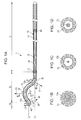
Fig. 1A illustrates the entirety of a guidewire according to an embodiment,Fig. 1B is a cross-sectional view of the guidewire taken along the line IB-IB ofFig. 1A, Fig. 1C is a cross-sectional view of the guidewire taken along the line IC-IC ofFig. 1A, and Fig. 1D is a cross-sectional view of the guidewire taken along the line ID-ID ofFig. 1A ; -
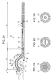
Fig. 2A illustrates the entirety of a guidewire according to another embodiment,Fig. 2B is a cross-sectional view of the guidewire taken along the line IIB-IIB ofFig. 2A, Fig. 2C is a cross-sectional view of the guidewire taken along the line IIC-IIC ofFig. 2A, and Fig. 2D is a cross-sectional view of the guidewire taken along the line IID-IID ofFig. 2A ; -
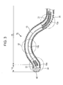
Fig. 3 is an enlarged view of a distal region of a guidewire according to another embodiment; -
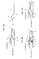
Figs. 4A to 4C illustrate a movement of the guidewire according to the embodiment inside a peripheral blood vessel, whereFig. 4A illustrates the state where the distal tip of the guidewire is stuck on a side branch,Fig. 4B illustrates the state where the guidewire is further pushed toward the distal end side while the distal tip is in the state of being stuck, andFig. 4C illustrates the state where the distal tip of the guidewire is released from the side branch and returns to a main branch; and -
Figs. 5A to 5C illustrate a movement of an existing guidewire inside a peripheral blood vessel, whereFig. 5A illustrates the state where the distal tip of the guidewire is stuck on a side branch,Fig. 5B illustrates the state where a distal region of the guidewire is formed into a loop after the guidewire is further pushed toward the distal end side while the distal tip is in the state of being stuck, andFig. 5C illustrates the state where the guidewire is deformed. - Referring now to
Fig. 1A to Fig. 5C , aguidewire 1 according to an embodiment is described as an example. ThroughoutFig. 1A to Fig. 5C , the left side is a distal end side (far side) that is inserted into a body while the right side is a proximal end side (a near side or a base side) that is manipulated by a technician such as a doctor. For ease of understanding, components such as acore shaft 10, acoil body 20, andcurved portions guidewire 1 in the axial direction (lengthwise direction) is reduced to schematically illustrate the entire configuration and thus the ratios of the entire dimensions are not the same as the actual ones. - The
guidewire 1 illustrated inFig. 1A mainly includes acore shaft 10, acoil body 20 that surrounds the outer periphery of thecore shaft 10, and adistal fixture 40 that fixes the distal end of thecore shaft 10 and the distal end of thecoil body 20 together. - The
core shaft 10 includes alarge diameter portion 11 on the proximal end side, ataper portion 12 on the distal end side of thelarge diameter portion 11, and asmall diameter portion 13 on the distal end side of thetaper portion 12. The outside diameter of thetaper portion 12 decreases toward the distal end side. - The
guidewire 1 also includes anintermediate fixture 42 in thetaper portion 12 and aproximal fixture 44 in thelarge diameter portion 11 in order to fix thecore shaft 10 and thecoil body 20 together. - In a state where an external force is not applied to the
guidewire 1, adistal region 15 of theguidewire 1 includes three curved portions, which are a firstcurved portion 30, a secondcurved portion 32, and a thirdcurved portion 34 in order from the proximal end side. The firstcurved portion 30 is curved in afirst direction 31. The secondcurved portion 32 formed on the distal end side of the firstcurved portion 30 is curved in asecond direction 33, which is different from thefirst direction 31. The thirdcurved portion 34 formed on the distal end side of the secondcurved portion 32 is curved in athird direction 35, which is different from thesecond direction 33. - Although the
first direction 31 and thethird direction 35 are different directions in this embodiment, the present invention is not limited to this configuration. Thefirst direction 31 and thethird direction 35 may be the same direction. - The
guidewire 1 includes adistal tip 14, adistal region 15 on the proximal end side of thedistal tip 14, and alinear body portion 16 on the proximal end side of thedistal region 15. Thedistal tip 14 extends from the thirdcurved portion 34 toward the distal end side. Thedistal region 15 includes the firstcurved portion 30, the secondcurved portion 32, and the thirdcurved portion 34. An axial direction (longitudinal direction) L1 of thebody portion 16 and an axial direction (longitudinal direction) L2 of thedistal tip 14 are parallel to each other. Thedistal tip 14 is positioned higher than the firstcurved portion 30 but lower than the secondcurved portion 32. In other words, a thirdcurved shaft portion 13c in thedistal tip 14 is positioned at a height between a firstcurved shaft portion 13a in the firstcurved portion 30 and a secondcurved shaft portion 13b in the secondcurved portion 32. Thus, thedistal tip 14 of theguidewire 1 extends in the axial direction L2 shifted from the axial direction L1 of thebody portion 16. -
Fig. 1B is a cross-sectional view of the firstcurved portion 30 taken along the line IB-IB ofFig. 1A. Fig. 1C is a cross-sectional view of the secondcurved portion 32 taken along the line IC-IC ofFig. 1A. Fig. 1D is a cross-sectional view of the thirdcurved portion 34 taken along the line ID-ID ofFig. 1A . The outside diameter of a secondcurved shaft portion 13b in the secondcurved portion 32 is smaller than the outside diameter of a firstcurved shaft portion 13a in the firstcurved portion 30 and the outside diameter of a thirdcurved shaft portion 13c in the thirdcurved portion 34. On the other hand, the outside diameter of thecoil body 20 in the secondcurved portion 32 is the same as the outside diameter of thecoil body 20 in the firstcurved portion 30 and the thirdcurved portion 34. For ease of understanding, the differences in outside diameter between thecore shafts Fig. 1B to Fig. 1D . - Consequently, the second
curved portion 32 has higher flexibility than the firstcurved portion 30 and the thirdcurved portion 34. In addition, since the outside diameter of thecoil body 20 in thedistal region 15 is constant, a force of a doctor pushing theguidewire 1 can be transmitted to the distal end of theguidewire 1 without being attenuated. - Now, an operation of the
guidewire 1 according to the embodiment performed when theguidewire 1 is inserted into a peripheral blood vessel is described. - When the
guidewire 1 is inserted into a peripheral blood vessel, thedistal tip 14 of theguidewire 1 may become stuck on a side branch of abifurcation 50 at which a main branch and the side branch bifurcates at an acute angle (seeFig. 4A ). If a doctor pushes theguidewire 1 toward the distal end side while thedistal tip 14 of theguidewire 1 is stuck on the side branch, a portion around the secondcurved portion 32 can bend to a large degree because the flexibility of the secondcurved portion 32 is higher than that of the firstcurved portion 30 and the third curved portion 34 (seeFig. 4B ). - Specifically, due to the
force 60 of a doctor pushing theguidewire 1 toward the distal end side (hereinafter this force is referred to as an initial distal-direction force 60), aforce 60a of pushing theguidewire 1 toward the distal end side (hereinafter this force is referred to as a transmitted distal-direction force 60a) and aforce 61 of pushing theguidewire 1 outward (hereinafter this force is referred to as an outward force 61) are applied to the secondcurved portion 32. Since the secondcurved portion 32 has flexibility, the secondcurved portion 32 can bend toward the distal end side while being in contact with the side wall of the main branch. Thus, the amount of the initial distal-direction force 60 that is converted into theoutward force 61 is reduced compared to that in the case of a conventional guidewire. In other words, since the transmitted distal-direction force 60a is far larger than theoutward force 61 in the secondcurved portion 32, the difference between the transmitted distal-direction force 60a and aresultant force 62, obtained by composition of the transmitted distal-direction force 60a and theoutward force 61, is negligible. The second curved portion moves toward the distal end side by receiving theresultant force 62 and thus thedistal tip 14 of theguidewire 1 returns toward the proximal end side by a proximal-direction force 63. Consequently, theguidewire 1 that is in a state of being stuck on the side branch is naturally released from the side branch. - Thus, in a portion around the second
curved portion 32 of theguidewire 1 according to this embodiment, theoutward force 61 exerted on the side wall of the main branch decreases further and the transmitted distal-direction force 60a accordingly increases compared to those in the case of a guidewire in which the secondcurved portion 32 has higher stiffness than the thirdcurved portion 34. Thus, theguidewire 1 is less likely to be rotated around the secondcurved portion 32. Consequently, thedistal tip 14 of theguidewire 1 released from the side branch can normally move through the main branch without being formed into a loop (seeFig. 4C ). - In a state where an external force is not applied to the
guidewire 1, thedistal tip 14 of theguidewire 1 extends from the thirdcurved portion 34 toward the distal end side in the axial direction L2, which is shifted from the axial direction L1 of thebody portion 16 so as to be parallel to the axial direction L1. Thus, the initial distal-direction force 60 is easily transmittable to thedistal tip 14. - In addition, the
distal tip 14 of theguidewire 1 extends in the axial direction L2 that is shifted so as to be parallel to the axial direction L1 of the body portion 16 (in other words, thedistal tip 14 of theguidewire 1 is positioned at a height between the firstcurved portion 30 and the secondcurved portion 32 and extends toward the distal end side in the axial direction L2 parallel to the axial direction L1 of the body portion 16). Thus, even in the case where thedistal tip 14 of theguidewire 1 is not stuck on the side branch (in other words, in the case where thedistal tip 14 of theguidewire 1 normally moves through the main branch), theguidewire 1 has the following advantages. In a peripheral blood vessel having a small diameter, the secondcurved portion 32 of theguidewire 1 frequently comes into contact with the side wall of a main branch. When a doctor pushes theguidewire 1 toward the distal end side while the secondcurved portion 32 is in contact with the side wall of a main branch, the distal-direction force and the outward force are exerted on a portion around the secondcurved portion 32 as in the case where thedistal tip 14 of theguidewire 1 becomes stuck on a side branch. Here, by using reaction against the force of pushing the secondcurved portion 32 outward against the side wall of the main branch, the direction in which thedistal tip 14 of theguidewire 1 extends can be slightly changed toward a direction perpendicular to the axial directions L1 and L2 of theguidewire 1. Particularly, it is preferable that thedistal tip 14 of theguidewire 1 be positioned at a height closer to the secondcurved portion 32 than to the firstcurved portion 30 because, in this positioning, the direction in which thedistal tip 14 of theguidewire 1 extends can be easily changed in response to the above-described reaction. - As described above, in the state where an external force is not applied to the
guidewire 1, thedistal tip 14 of theguidewire 1 extends from the thirdcurved portion 34 toward the distal end side in the axial direction L2 parallel to the axial direction L1 of thebody portion 16 and positioned higher than the firstcurved portion 30 but lower than the secondcurved portion 32. Thus, the direction in which theguidewire 1 moves can be flexibly changed even when theguidewire 1 moves through a sharply curved main branch of a peripheral blood vessel. Consequently, a highlysteerable guidewire 1 can be provided. - Now, materials of which the components of the
guidewire 1 according to this embodiment are made will be described, although the invention is not limited to these materials. - Superelastic alloy such as stainless steel (Japanese Industrial Standards (JIS) No. SUS304 or SUS316) or Ni-Ti alloy can be used for the
core shaft 10 including thelarge diameter portion 11, thetaper portion 12, and thesmall diameter portion 13. - The material of the
coil body 20 is not particularly limited, but a stainless steel is used in this embodiment. A single coil body formed of one strand or a multi-strand coil body formed of multiple strands may be used as thecoil body 20. Since a multi-strand coil body has higher breaking strength and higher flexibility than a single coil body, it is preferable to use a multi-strand coil body. A hollow coil body obtained by stranding multiple strands into a hollow shape may be used as a multi-strand coil body. - A hard solder material (aluminum alloy, silver, or gold) or a metal solder (such as Ag-Sn alloy or Au-Sn alloy) may be used as the materials of the
distal fixture 40, theintermediate fixture 42, and theproximal fixture 44. - In the
guidewire 1 according to the embodiment, the outside diameter of the secondcurved shaft portion 13b is smaller than the outside diameter of the firstcurved shaft portion 13a and the outside diameter of the thirdcurved shaft portion 13c so that the secondcurved portion 32 has higher flexibility than the firstcurved portion 30 and the thirdcurved portion 34. However, the present invention is not limited to this configuration. As illustrated inFig. 2A and Fig. 2C , aguidewire 1a according to another embodiment may have a secondcurved shaft portion 13d of a flat-plate shape. When the secondcurved shaft portion 13d has a flat-plate shape, the secondcurved shaft portion 13d is made less likely to be plastically deformed. In other words, the secondcurved portion 32 can maintain its shape even after theguidewire 1a is used multiple times. - As illustrated in
Fig. 3 , aguidewire 1b according to another embodiment may includesecond coil bodies coil body 20, in the firstcurved portion 30 and the thirdcurved portion 34. Thesecond coil bodies small diameter portion 13 of thecore shaft 10 and thecoil body 20. Specifically, in theguidewire 1b, the outer periphery of the firstcurved shaft portion 13a in the firstcurved portion 30 is covered by thesecond coil body 21 and the outer periphery of the thirdcurved shaft portion 13c in the thirdcurved portion 34 is covered by thesecond coil body 22, whereas the outer periphery of the secondcurved shaft portion 13b in the secondcurved portion 32 is not covered by a second coil body. Thus, the secondcurved portion 32 can have higher flexibility than the firstcurved portion 30 and the thirdcurved portion 34. - As in the case of the
guidewire 1 and theguidewire 1a, asmall diameter portion 13 of acore shaft 10 of theguidewire 1b may be formed such that a firstcurved portion 30, a secondcurved portion 32, and a thirdcurved portion 34 have different outside diameters. However, since the stiffness of the firstcurved portion 30 and the stiffness of the thirdcurved portion 34 can be increased by providing thesecond coil bodies small diameter portion 13 of thecore shaft 10 such that the firstcurved portion 30, the secondcurved portion 32, and the thirdcurved portion 34 have the same outside diameter. - In the case where the
second coil bodies second coil body 22 only has to be smaller than that of thesecond coil body 21 so as to make the thirdcurved portion 34 more flexible than the firstcurved portion 30. In the case where thesecond coil bodies second coil body 22 only has to be made of a material that is more flexible than a material of thesecond coil body 21 so as to make the thirdcurved portion 34 more flexible than the firstcurved portion 30. - Although not illustrated in
Fig. 3 , both ends of thesecond coil bodies small diameter portion 13 of thecore shaft 10 by brazing or soldering using a hard solder material or a metal solder, as in the case of thefixtures second coil bodies - As described above, in each of the
guidewires curved portion 32 has higher flexibility than the firstcurved portion 30 and the thirdcurved portion 34 and thus a portion around the secondcurved portion 32 can bend to a large degree. Consequently, thedistal tip 14 of theguidewire 1, in a state of being stuck on a side branch, can be released from the side branch and thedistal region 15 can be prevented from being rotated around the secondcurved portion 32.
Claims (3)
- A guidewire (1) comprising:a core shaft; anda coil body that surrounds an outer periphery of the core shaft,wherein a distal region (15) of the guidewire (1) includes
a first curved portion (30) that is curved in a first direction,
a second curved portion (32) located on a distal end side of the first curved portion (30), the second curved portion (32) being curved in a second direction, which is different from the first direction, and
a third curved portion (34) located on a distal end side of the second curved portion (32), the third curved portion (34) being curved in a third direction, which is different from the second direction, andwherein the second curved portion (32) has higher flexibility than the first curved portion (30) and the third curved portion (34). - The guidewire (1) according to Claim 1,
wherein an outside diameter of the core shaft in the second curved portion (32) is smaller than an outside diameter of the core shaft in the first curved portion (30) and an outside diameter of the core shaft in the third curved portion (34), and
wherein an outside diameter of the coil body in the second curved portion (32) is the same as an outside diameter of the coil body in the first curved portion (30) and an outside diameter of the coil body in the third curved portion (34). - The guidewire (1) according to Claim 1 or 2, wherein a linear body portion is located on a proximal end side of the distal region (15), and
wherein a distal tip (14) of the guidewire (1) extends toward a distal end side of the guidewire in a direction shifted from a direction in which an axis of the body portion extends.
Applications Claiming Priority (1)
| Application Number | Priority Date | Filing Date | Title |
|---|---|---|---|
| JP2012266896A JP5780525B2 (en) | 2012-12-06 | 2012-12-06 | Guide wire |
Publications (3)
| Publication Number | Publication Date |
|---|---|
| EP2740513A1 true EP2740513A1 (en) | 2014-06-11 |
| EP2740513B1 EP2740513B1 (en) | 2019-01-09 |
| EP2740513B8 EP2740513B8 (en) | 2019-03-13 |
Family
ID=49378032
Family Applications (1)
| Application Number | Title | Priority Date | Filing Date |
|---|---|---|---|
| EP13186569.3A Not-in-force EP2740513B8 (en) | 2012-12-06 | 2013-09-30 | Guidewire |
Country Status (4)
| Country | Link |
|---|---|
| US (1) | US20140163420A1 (en) |
| EP (1) | EP2740513B8 (en) |
| JP (1) | JP5780525B2 (en) |
| CN (1) | CN103845785B (en) |
Cited By (2)
| Publication number | Priority date | Publication date | Assignee | Title |
|---|---|---|---|---|
| EP3530309A1 (en) * | 2018-02-27 | 2019-08-28 | Johan Willem Pieter Marsman | Autonomous guidewire |
| EP3785757A1 (en) * | 2019-08-28 | 2021-03-03 | Johan Willem Pieter Marsman | Guidewire kit |
Families Citing this family (10)
| Publication number | Priority date | Publication date | Assignee | Title |
|---|---|---|---|---|
| JP2015137428A (en) * | 2014-01-20 | 2015-07-30 | 朝日インテック株式会社 | Twisted wire and guide wire using the twisted wire |
| JP2016013269A (en) * | 2014-07-02 | 2016-01-28 | 朝日インテック株式会社 | Guide wire |
| WO2016028486A1 (en) * | 2014-08-21 | 2016-02-25 | Boston Scientific Scimed, Inc. | Medical device with support member |
| EP3544488A2 (en) | 2016-11-28 | 2019-10-02 | Sensome | Insertable device for in vivo sensing |
| WO2019202699A1 (en) * | 2018-04-19 | 2019-10-24 | オリンパス株式会社 | Medical device |
| CN109758661B (en) * | 2018-08-24 | 2021-11-23 | 中国医学科学院阜外医院 | Preformed guide wire for treating bifurcation lesion in blood vessel |
| CN109876280A (en) * | 2019-04-03 | 2019-06-14 | 张健 | A kind of the Big Dipper moulding superslide Yarn guide component |
| CN112438768A (en) * | 2019-08-29 | 2021-03-05 | 微创神通医疗科技(上海)有限公司 | Conveying device and lumen implantation system |
| CA3156632C (en) * | 2019-10-16 | 2025-09-23 | Embrace Medical Ltd. | Guidewire with elastically articulatable tip |
| EP4190384A4 (en) * | 2020-07-27 | 2024-07-17 | Asahi Intecc Co., Ltd. | Catheter |
Citations (6)
| Publication number | Priority date | Publication date | Assignee | Title |
|---|---|---|---|---|
| JPH1176415A (en) | 1997-09-10 | 1999-03-23 | Terumo Corp | Guide wire |
| US20040167436A1 (en) * | 2003-02-26 | 2004-08-26 | Reynolds Brian R. | Elongate medical device with distal cap |
| JP2007105531A (en) | 2007-01-30 | 2007-04-26 | Aruze Corp | Play equipment |
| WO2009039063A1 (en) * | 2007-09-18 | 2009-03-26 | Cook Incorporated | Wire guide |
| EP2361652A1 (en) * | 2010-02-19 | 2011-08-31 | Asahi Intecc Co., Ltd. | Guidewire |
| EP2402051A1 (en) * | 2010-06-30 | 2012-01-04 | PatentStra Co. Ltd. | Medical guide wire |
Family Cites Families (9)
| Publication number | Priority date | Publication date | Assignee | Title |
|---|---|---|---|---|
| US5007434A (en) * | 1989-02-07 | 1991-04-16 | Advanced Cardiovascular Systems, Inc. | Catheter tip attitude controlling guide wire |
| EP0495299A1 (en) * | 1990-12-03 | 1992-07-22 | C.R. Bard, Inc. | Guidewire tip construction |
| US7494474B2 (en) * | 1997-06-04 | 2009-02-24 | Advanced Cardiovascular Systems, Inc. | Polymer coated guidewire |
| JPH11216188A (en) * | 1997-10-27 | 1999-08-10 | Cordis Corp | Guiding wire with outer sheath |
| WO2004018031A2 (en) * | 2002-08-22 | 2004-03-04 | William A. Cook Australia Pty. Ltd. | Guide wire |
| US7824345B2 (en) * | 2003-12-22 | 2010-11-02 | Boston Scientific Scimed, Inc. | Medical device with push force limiter |
| CN101384293B (en) * | 2006-03-06 | 2013-04-24 | 泰尔茂株式会社 | Guide wire |
| IL181760A0 (en) * | 2007-03-07 | 2007-07-04 | Ran Carmeli | Medical device |
| IT1391568B1 (en) * | 2008-09-05 | 2012-01-11 | E V R Endovascular Res Es S A | CABLE GUIDE TO NAVIGATION THROUGH AN ANATOMY WITH BRANCHED DUCTS |
-
2012
- 2012-12-06 JP JP2012266896A patent/JP5780525B2/en not_active Expired - Fee Related
-
2013
- 2013-09-16 CN CN201310421131.2A patent/CN103845785B/en not_active Expired - Fee Related
- 2013-09-30 EP EP13186569.3A patent/EP2740513B8/en not_active Not-in-force
- 2013-10-02 US US14/044,423 patent/US20140163420A1/en not_active Abandoned
Patent Citations (6)
| Publication number | Priority date | Publication date | Assignee | Title |
|---|---|---|---|---|
| JPH1176415A (en) | 1997-09-10 | 1999-03-23 | Terumo Corp | Guide wire |
| US20040167436A1 (en) * | 2003-02-26 | 2004-08-26 | Reynolds Brian R. | Elongate medical device with distal cap |
| JP2007105531A (en) | 2007-01-30 | 2007-04-26 | Aruze Corp | Play equipment |
| WO2009039063A1 (en) * | 2007-09-18 | 2009-03-26 | Cook Incorporated | Wire guide |
| EP2361652A1 (en) * | 2010-02-19 | 2011-08-31 | Asahi Intecc Co., Ltd. | Guidewire |
| EP2402051A1 (en) * | 2010-06-30 | 2012-01-04 | PatentStra Co. Ltd. | Medical guide wire |
Cited By (4)
| Publication number | Priority date | Publication date | Assignee | Title |
|---|---|---|---|---|
| EP3530309A1 (en) * | 2018-02-27 | 2019-08-28 | Johan Willem Pieter Marsman | Autonomous guidewire |
| US11324931B2 (en) | 2018-02-27 | 2022-05-10 | Johan Willem Pieter Marsman | Autonomous guidewire |
| EP3785757A1 (en) * | 2019-08-28 | 2021-03-03 | Johan Willem Pieter Marsman | Guidewire kit |
| US11331455B2 (en) | 2019-08-28 | 2022-05-17 | Johan Willem Pieter Marsman | Guidewire kit |
Also Published As
| Publication number | Publication date |
|---|---|
| EP2740513B1 (en) | 2019-01-09 |
| JP5780525B2 (en) | 2015-09-16 |
| CN103845785B (en) | 2015-11-04 |
| CN103845785A (en) | 2014-06-11 |
| US20140163420A1 (en) | 2014-06-12 |
| JP2014113177A (en) | 2014-06-26 |
| EP2740513B8 (en) | 2019-03-13 |
Similar Documents
| Publication | Publication Date | Title |
|---|---|---|
| EP2740513B1 (en) | Guidewire | |
| EP2689795B1 (en) | Guidewire | |
| EP2417999B1 (en) | Guidewire with bent portion fixed with a fixing member | |
| EP2962718B1 (en) | Guidewire | |
| JP4863321B2 (en) | Medical guidewire | |
| US7322944B2 (en) | Guide wire | |
| EP2656870A1 (en) | Guidewire | |
| EP2586483A1 (en) | Guidewire | |
| JP4963326B2 (en) | Guide wire | |
| WO2016047499A1 (en) | Guide wire | |
| EP2332608A2 (en) | Guidewire | |
| EP2937109B1 (en) | Guidewire | |
| JP2013111320A (en) | Guide wire | |
| JP6405274B2 (en) | Guide wire | |
| EP2921197B1 (en) | Guidewire | |
| EP2559452A1 (en) | Guidewire | |
| KR102427995B1 (en) | guide wire | |
| US20150119757A1 (en) | Coil body and guide wire | |
| US12151069B2 (en) | Guide wire | |
| US20170120018A1 (en) | Guidewire | |
| US20220096802A1 (en) | Guide wire | |
| EP3501588A1 (en) | Guidewire | |
| EP4360688A1 (en) | Guide wire | |
| WO2024236759A1 (en) | Blood vessel guide wire | |
| WO2024236760A1 (en) | Blood vessel guide wire and method for imaging blood vessel guide wire |
Legal Events
| Date | Code | Title | Description |
|---|---|---|---|
| PUAI | Public reference made under article 153(3) epc to a published international application that has entered the european phase |
Free format text: ORIGINAL CODE: 0009012 |
|
| 17P | Request for examination filed |
Effective date: 20130930 |
|
| AK | Designated contracting states |
Kind code of ref document: A1 Designated state(s): AL AT BE BG CH CY CZ DE DK EE ES FI FR GB GR HR HU IE IS IT LI LT LU LV MC MK MT NL NO PL PT RO RS SE SI SK SM TR |
|
| AX | Request for extension of the european patent |
Extension state: BA ME |
|
| R17P | Request for examination filed (corrected) |
Effective date: 20140522 |
|
| RBV | Designated contracting states (corrected) |
Designated state(s): AL AT BE BG CH CY CZ DE DK EE ES FI FR GB GR HR HU IE IS IT LI LT LU LV MC MK MT NL NO PL PT RO RS SE SI SK SM TR |
|
| 17Q | First examination report despatched |
Effective date: 20150610 |
|
| STAA | Information on the status of an ep patent application or granted ep patent |
Free format text: STATUS: EXAMINATION IS IN PROGRESS |
|
| GRAP | Despatch of communication of intention to grant a patent |
Free format text: ORIGINAL CODE: EPIDOSNIGR1 |
|
| STAA | Information on the status of an ep patent application or granted ep patent |
Free format text: STATUS: GRANT OF PATENT IS INTENDED |
|
| INTG | Intention to grant announced |
Effective date: 20180727 |
|
| GRAS | Grant fee paid |
Free format text: ORIGINAL CODE: EPIDOSNIGR3 |
|
| GRAA | (expected) grant |
Free format text: ORIGINAL CODE: 0009210 |
|
| STAA | Information on the status of an ep patent application or granted ep patent |
Free format text: STATUS: THE PATENT HAS BEEN GRANTED |
|
| AK | Designated contracting states |
Kind code of ref document: B1 Designated state(s): AL AT BE BG CH CY CZ DE DK EE ES FI FR GB GR HR HU IE IS IT LI LT LU LV MC MK MT NL NO PL PT RO RS SE SI SK SM TR |
|
| REG | Reference to a national code |
Ref country code: GB Ref legal event code: FG4D |
|
| REG | Reference to a national code |
Ref country code: CH Ref legal event code: EP Ref country code: AT Ref legal event code: REF Ref document number: 1086558 Country of ref document: AT Kind code of ref document: T Effective date: 20190115 |
|
| RAP2 | Party data changed (patent owner data changed or rights of a patent transferred) |
Owner name: ASAHI INTECC CO., LTD. |
|
| REG | Reference to a national code |
Ref country code: IE Ref legal event code: FG4D |
|
| REG | Reference to a national code |
Ref country code: DE Ref legal event code: R096 Ref document number: 602013049468 Country of ref document: DE |
|
| REG | Reference to a national code |
Ref country code: CH Ref legal event code: PK Free format text: BERICHTIGUNG B8 |
|
| REG | Reference to a national code |
Ref country code: NL Ref legal event code: MP Effective date: 20190109 |
|
| REG | Reference to a national code |
Ref country code: LT Ref legal event code: MG4D |
|
| PG25 | Lapsed in a contracting state [announced via postgrant information from national office to epo] |
Ref country code: NL Free format text: LAPSE BECAUSE OF FAILURE TO SUBMIT A TRANSLATION OF THE DESCRIPTION OR TO PAY THE FEE WITHIN THE PRESCRIBED TIME-LIMIT Effective date: 20190109 |
|
| REG | Reference to a national code |
Ref country code: AT Ref legal event code: MK05 Ref document number: 1086558 Country of ref document: AT Kind code of ref document: T Effective date: 20190109 |
|
| PG25 | Lapsed in a contracting state [announced via postgrant information from national office to epo] |
Ref country code: PT Free format text: LAPSE BECAUSE OF FAILURE TO SUBMIT A TRANSLATION OF THE DESCRIPTION OR TO PAY THE FEE WITHIN THE PRESCRIBED TIME-LIMIT Effective date: 20190509 Ref country code: NO Free format text: LAPSE BECAUSE OF FAILURE TO SUBMIT A TRANSLATION OF THE DESCRIPTION OR TO PAY THE FEE WITHIN THE PRESCRIBED TIME-LIMIT Effective date: 20190409 Ref country code: ES Free format text: LAPSE BECAUSE OF FAILURE TO SUBMIT A TRANSLATION OF THE DESCRIPTION OR TO PAY THE FEE WITHIN THE PRESCRIBED TIME-LIMIT Effective date: 20190109 Ref country code: PL Free format text: LAPSE BECAUSE OF FAILURE TO SUBMIT A TRANSLATION OF THE DESCRIPTION OR TO PAY THE FEE WITHIN THE PRESCRIBED TIME-LIMIT Effective date: 20190109 Ref country code: LT Free format text: LAPSE BECAUSE OF FAILURE TO SUBMIT A TRANSLATION OF THE DESCRIPTION OR TO PAY THE FEE WITHIN THE PRESCRIBED TIME-LIMIT Effective date: 20190109 Ref country code: SE Free format text: LAPSE BECAUSE OF FAILURE TO SUBMIT A TRANSLATION OF THE DESCRIPTION OR TO PAY THE FEE WITHIN THE PRESCRIBED TIME-LIMIT Effective date: 20190109 Ref country code: FI Free format text: LAPSE BECAUSE OF FAILURE TO SUBMIT A TRANSLATION OF THE DESCRIPTION OR TO PAY THE FEE WITHIN THE PRESCRIBED TIME-LIMIT Effective date: 20190109 |
|
| PG25 | Lapsed in a contracting state [announced via postgrant information from national office to epo] |
Ref country code: RS Free format text: LAPSE BECAUSE OF FAILURE TO SUBMIT A TRANSLATION OF THE DESCRIPTION OR TO PAY THE FEE WITHIN THE PRESCRIBED TIME-LIMIT Effective date: 20190109 Ref country code: BG Free format text: LAPSE BECAUSE OF FAILURE TO SUBMIT A TRANSLATION OF THE DESCRIPTION OR TO PAY THE FEE WITHIN THE PRESCRIBED TIME-LIMIT Effective date: 20190409 Ref country code: GR Free format text: LAPSE BECAUSE OF FAILURE TO SUBMIT A TRANSLATION OF THE DESCRIPTION OR TO PAY THE FEE WITHIN THE PRESCRIBED TIME-LIMIT Effective date: 20190410 Ref country code: LV Free format text: LAPSE BECAUSE OF FAILURE TO SUBMIT A TRANSLATION OF THE DESCRIPTION OR TO PAY THE FEE WITHIN THE PRESCRIBED TIME-LIMIT Effective date: 20190109 Ref country code: IS Free format text: LAPSE BECAUSE OF FAILURE TO SUBMIT A TRANSLATION OF THE DESCRIPTION OR TO PAY THE FEE WITHIN THE PRESCRIBED TIME-LIMIT Effective date: 20190509 Ref country code: HR Free format text: LAPSE BECAUSE OF FAILURE TO SUBMIT A TRANSLATION OF THE DESCRIPTION OR TO PAY THE FEE WITHIN THE PRESCRIBED TIME-LIMIT Effective date: 20190109 |
|
| REG | Reference to a national code |
Ref country code: DE Ref legal event code: R097 Ref document number: 602013049468 Country of ref document: DE |
|
| PG25 | Lapsed in a contracting state [announced via postgrant information from national office to epo] |
Ref country code: EE Free format text: LAPSE BECAUSE OF FAILURE TO SUBMIT A TRANSLATION OF THE DESCRIPTION OR TO PAY THE FEE WITHIN THE PRESCRIBED TIME-LIMIT Effective date: 20190109 Ref country code: IT Free format text: LAPSE BECAUSE OF FAILURE TO SUBMIT A TRANSLATION OF THE DESCRIPTION OR TO PAY THE FEE WITHIN THE PRESCRIBED TIME-LIMIT Effective date: 20190109 Ref country code: DK Free format text: LAPSE BECAUSE OF FAILURE TO SUBMIT A TRANSLATION OF THE DESCRIPTION OR TO PAY THE FEE WITHIN THE PRESCRIBED TIME-LIMIT Effective date: 20190109 Ref country code: SK Free format text: LAPSE BECAUSE OF FAILURE TO SUBMIT A TRANSLATION OF THE DESCRIPTION OR TO PAY THE FEE WITHIN THE PRESCRIBED TIME-LIMIT Effective date: 20190109 Ref country code: AL Free format text: LAPSE BECAUSE OF FAILURE TO SUBMIT A TRANSLATION OF THE DESCRIPTION OR TO PAY THE FEE WITHIN THE PRESCRIBED TIME-LIMIT Effective date: 20190109 Ref country code: CZ Free format text: LAPSE BECAUSE OF FAILURE TO SUBMIT A TRANSLATION OF THE DESCRIPTION OR TO PAY THE FEE WITHIN THE PRESCRIBED TIME-LIMIT Effective date: 20190109 Ref country code: AT Free format text: LAPSE BECAUSE OF FAILURE TO SUBMIT A TRANSLATION OF THE DESCRIPTION OR TO PAY THE FEE WITHIN THE PRESCRIBED TIME-LIMIT Effective date: 20190109 Ref country code: RO Free format text: LAPSE BECAUSE OF FAILURE TO SUBMIT A TRANSLATION OF THE DESCRIPTION OR TO PAY THE FEE WITHIN THE PRESCRIBED TIME-LIMIT Effective date: 20190109 |
|
| PLBE | No opposition filed within time limit |
Free format text: ORIGINAL CODE: 0009261 |
|
| STAA | Information on the status of an ep patent application or granted ep patent |
Free format text: STATUS: NO OPPOSITION FILED WITHIN TIME LIMIT |
|
| PG25 | Lapsed in a contracting state [announced via postgrant information from national office to epo] |
Ref country code: SM Free format text: LAPSE BECAUSE OF FAILURE TO SUBMIT A TRANSLATION OF THE DESCRIPTION OR TO PAY THE FEE WITHIN THE PRESCRIBED TIME-LIMIT Effective date: 20190109 |
|
| 26N | No opposition filed |
Effective date: 20191010 |
|
| PG25 | Lapsed in a contracting state [announced via postgrant information from national office to epo] |
Ref country code: SI Free format text: LAPSE BECAUSE OF FAILURE TO SUBMIT A TRANSLATION OF THE DESCRIPTION OR TO PAY THE FEE WITHIN THE PRESCRIBED TIME-LIMIT Effective date: 20190109 |
|
| PG25 | Lapsed in a contracting state [announced via postgrant information from national office to epo] |
Ref country code: TR Free format text: LAPSE BECAUSE OF FAILURE TO SUBMIT A TRANSLATION OF THE DESCRIPTION OR TO PAY THE FEE WITHIN THE PRESCRIBED TIME-LIMIT Effective date: 20190109 |
|
| PG25 | Lapsed in a contracting state [announced via postgrant information from national office to epo] |
Ref country code: MC Free format text: LAPSE BECAUSE OF FAILURE TO SUBMIT A TRANSLATION OF THE DESCRIPTION OR TO PAY THE FEE WITHIN THE PRESCRIBED TIME-LIMIT Effective date: 20190109 |
|
| REG | Reference to a national code |
Ref country code: CH Ref legal event code: PL |
|
| PG25 | Lapsed in a contracting state [announced via postgrant information from national office to epo] |
Ref country code: LU Free format text: LAPSE BECAUSE OF NON-PAYMENT OF DUE FEES Effective date: 20190930 Ref country code: IE Free format text: LAPSE BECAUSE OF NON-PAYMENT OF DUE FEES Effective date: 20190930 Ref country code: LI Free format text: LAPSE BECAUSE OF NON-PAYMENT OF DUE FEES Effective date: 20190930 Ref country code: CH Free format text: LAPSE BECAUSE OF NON-PAYMENT OF DUE FEES Effective date: 20190930 |
|
| REG | Reference to a national code |
Ref country code: BE Ref legal event code: MM Effective date: 20190930 |
|
| PG25 | Lapsed in a contracting state [announced via postgrant information from national office to epo] |
Ref country code: BE Free format text: LAPSE BECAUSE OF NON-PAYMENT OF DUE FEES Effective date: 20190930 |
|
| PG25 | Lapsed in a contracting state [announced via postgrant information from national office to epo] |
Ref country code: CY Free format text: LAPSE BECAUSE OF FAILURE TO SUBMIT A TRANSLATION OF THE DESCRIPTION OR TO PAY THE FEE WITHIN THE PRESCRIBED TIME-LIMIT Effective date: 20190109 |
|
| PG25 | Lapsed in a contracting state [announced via postgrant information from national office to epo] |
Ref country code: MT Free format text: LAPSE BECAUSE OF FAILURE TO SUBMIT A TRANSLATION OF THE DESCRIPTION OR TO PAY THE FEE WITHIN THE PRESCRIBED TIME-LIMIT Effective date: 20190109 Ref country code: HU Free format text: LAPSE BECAUSE OF FAILURE TO SUBMIT A TRANSLATION OF THE DESCRIPTION OR TO PAY THE FEE WITHIN THE PRESCRIBED TIME-LIMIT; INVALID AB INITIO Effective date: 20130930 |
|
| PG25 | Lapsed in a contracting state [announced via postgrant information from national office to epo] |
Ref country code: MK Free format text: LAPSE BECAUSE OF FAILURE TO SUBMIT A TRANSLATION OF THE DESCRIPTION OR TO PAY THE FEE WITHIN THE PRESCRIBED TIME-LIMIT Effective date: 20190109 |
|
| PGFP | Annual fee paid to national office [announced via postgrant information from national office to epo] |
Ref country code: GB Payment date: 20230920 Year of fee payment: 11 |
|
| PGFP | Annual fee paid to national office [announced via postgrant information from national office to epo] |
Ref country code: FR Payment date: 20230928 Year of fee payment: 11 Ref country code: DE Payment date: 20230920 Year of fee payment: 11 |
|
| REG | Reference to a national code |
Ref country code: DE Ref legal event code: R119 Ref document number: 602013049468 Country of ref document: DE |
|
| GBPC | Gb: european patent ceased through non-payment of renewal fee |
Effective date: 20240930 |
|
| PG25 | Lapsed in a contracting state [announced via postgrant information from national office to epo] |
Ref country code: DE Free format text: LAPSE BECAUSE OF NON-PAYMENT OF DUE FEES Effective date: 20250401 |
|
| PG25 | Lapsed in a contracting state [announced via postgrant information from national office to epo] |
Ref country code: GB Free format text: LAPSE BECAUSE OF NON-PAYMENT OF DUE FEES Effective date: 20240930 |
|
| PG25 | Lapsed in a contracting state [announced via postgrant information from national office to epo] |
Ref country code: FR Free format text: LAPSE BECAUSE OF NON-PAYMENT OF DUE FEES Effective date: 20240930 |