EP2740406A1 - X-ray photography machine - Google Patents
X-ray photography machine Download PDFInfo
- Publication number
- EP2740406A1 EP2740406A1 EP13150045.6A EP13150045A EP2740406A1 EP 2740406 A1 EP2740406 A1 EP 2740406A1 EP 13150045 A EP13150045 A EP 13150045A EP 2740406 A1 EP2740406 A1 EP 2740406A1
- Authority
- EP
- European Patent Office
- Prior art keywords
- flange
- pulley
- drive shaft
- drive
- pressing member
- Prior art date
- Legal status (The legal status is an assumption and is not a legal conclusion. Google has not performed a legal analysis and makes no representation as to the accuracy of the status listed.)
- Granted
Links
- 210000000481 breast Anatomy 0.000 description 17
- 238000009607 mammography Methods 0.000 description 10
- 230000008878 coupling Effects 0.000 description 8
- 238000010168 coupling process Methods 0.000 description 8
- 238000005859 coupling reaction Methods 0.000 description 8
- 230000001419 dependent effect Effects 0.000 description 3
- 230000008901 benefit Effects 0.000 description 2
- 230000000694 effects Effects 0.000 description 2
- 206010006187 Breast cancer Diseases 0.000 description 1
- 208000026310 Breast neoplasm Diseases 0.000 description 1
- 208000004434 Calcinosis Diseases 0.000 description 1
- 206010033372 Pain and discomfort Diseases 0.000 description 1
- 230000002159 abnormal effect Effects 0.000 description 1
- 238000007792 addition Methods 0.000 description 1
- 230000005540 biological transmission Effects 0.000 description 1
- 238000007796 conventional method Methods 0.000 description 1
- 230000002708 enhancing effect Effects 0.000 description 1
- 230000003902 lesion Effects 0.000 description 1
- 238000012986 modification Methods 0.000 description 1
- 230000004048 modification Effects 0.000 description 1
- 238000006467 substitution reaction Methods 0.000 description 1
Images




Classifications
-
- A—HUMAN NECESSITIES
- A61—MEDICAL OR VETERINARY SCIENCE; HYGIENE
- A61B—DIAGNOSIS; SURGERY; IDENTIFICATION
- A61B6/00—Apparatus or devices for radiation diagnosis; Apparatus or devices for radiation diagnosis combined with radiation therapy equipment
- A61B6/02—Arrangements for diagnosis sequentially in different planes; Stereoscopic radiation diagnosis
- A61B6/03—Computed tomography [CT]
-
- A—HUMAN NECESSITIES
- A61—MEDICAL OR VETERINARY SCIENCE; HYGIENE
- A61B—DIAGNOSIS; SURGERY; IDENTIFICATION
- A61B6/00—Apparatus or devices for radiation diagnosis; Apparatus or devices for radiation diagnosis combined with radiation therapy equipment
- A61B6/04—Positioning of patients; Tiltable beds or the like
- A61B6/0407—Supports, e.g. tables or beds, for the body or parts of the body
- A61B6/0414—Supports, e.g. tables or beds, for the body or parts of the body with compression means
-
- A—HUMAN NECESSITIES
- A61—MEDICAL OR VETERINARY SCIENCE; HYGIENE
- A61B—DIAGNOSIS; SURGERY; IDENTIFICATION
- A61B6/00—Apparatus or devices for radiation diagnosis; Apparatus or devices for radiation diagnosis combined with radiation therapy equipment
- A61B6/44—Constructional features of apparatus for radiation diagnosis
-
- A—HUMAN NECESSITIES
- A61—MEDICAL OR VETERINARY SCIENCE; HYGIENE
- A61B—DIAGNOSIS; SURGERY; IDENTIFICATION
- A61B6/00—Apparatus or devices for radiation diagnosis; Apparatus or devices for radiation diagnosis combined with radiation therapy equipment
- A61B6/50—Apparatus or devices for radiation diagnosis; Apparatus or devices for radiation diagnosis combined with radiation therapy equipment specially adapted for specific body parts; specially adapted for specific clinical applications
- A61B6/502—Apparatus or devices for radiation diagnosis; Apparatus or devices for radiation diagnosis combined with radiation therapy equipment specially adapted for specific body parts; specially adapted for specific clinical applications for diagnosis of breast, i.e. mammography
-
- F—MECHANICAL ENGINEERING; LIGHTING; HEATING; WEAPONS; BLASTING
- F16—ENGINEERING ELEMENTS AND UNITS; GENERAL MEASURES FOR PRODUCING AND MAINTAINING EFFECTIVE FUNCTIONING OF MACHINES OR INSTALLATIONS; THERMAL INSULATION IN GENERAL
- F16D—COUPLINGS FOR TRANSMITTING ROTATION; CLUTCHES; BRAKES
- F16D27/00—Magnetically- or electrically- actuated clutches; Control or electric circuits therefor
- F16D27/02—Magnetically- or electrically- actuated clutches; Control or electric circuits therefor with electromagnets incorporated in the clutch, i.e. with collecting rings
- F16D27/04—Magnetically- or electrically- actuated clutches; Control or electric circuits therefor with electromagnets incorporated in the clutch, i.e. with collecting rings with axially-movable friction surfaces
- F16D27/06—Magnetically- or electrically- actuated clutches; Control or electric circuits therefor with electromagnets incorporated in the clutch, i.e. with collecting rings with axially-movable friction surfaces with friction surfaces arranged within the flux
-
- A—HUMAN NECESSITIES
- A61—MEDICAL OR VETERINARY SCIENCE; HYGIENE
- A61B—DIAGNOSIS; SURGERY; IDENTIFICATION
- A61B6/00—Apparatus or devices for radiation diagnosis; Apparatus or devices for radiation diagnosis combined with radiation therapy equipment
- A61B6/44—Constructional features of apparatus for radiation diagnosis
- A61B6/4429—Constructional features of apparatus for radiation diagnosis related to the mounting of source units and detector units
- A61B6/4435—Constructional features of apparatus for radiation diagnosis related to the mounting of source units and detector units the source unit and the detector unit being coupled by a rigid structure
- A61B6/4441—Constructional features of apparatus for radiation diagnosis related to the mounting of source units and detector units the source unit and the detector unit being coupled by a rigid structure the rigid structure being a C-arm or U-arm
Definitions
- the present invention relates to X-ray photography machines and, more particularly, to an X-ray photography machine that uses mammography.
- X-ray photography is used in a variety of medical fields.
- a mammography machine is a kind of X-ray photography machine which is used to detect breast cancer, lesions, microcalcification, etc.
- a representative conventional mammography machine was proposed in Korean Patent Laid-open Publication No. 10-2009-0112992 (entitled: Mammography machine having large-area digital sensor).
- mammography machines To examine the breast of a patient, the breast that is to be examined must be pressed.
- mammography machines include a pressing member which presses the breast, and a transfer apparatus which moves the pressing member.
- the pressing member presses the breast
- the patient feels pain and discomfort.
- an unexpected event such as power failure occurs
- the pressing member may be stopped while the breast is being pressed by the pressing member. In this case, the patient will almost certainly experience a sense of fear or embarrassment. Therefore, when an unexpected event occurs, the pressing member must be able to release the breast.
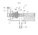
- FIG. 1 is a sectional view illustrating a conventional transfer apparatus (at present, unpublished) for mammography machines which was proposed by the applicant of the present invention.
- This transfer apparatus is configured such that, upon power interruption, a breast pressing operation is automatically stopped so as to release the breast of a patient.
- the transfer apparatus 170 of FIG. 1 includes a drive motor 171, a drive pulley 172a, a driven pulley 172b, a drive belt 173, a first drive shaft 174, a first pulley 175a, a second pulley 175b, a switch belt 176, a second drive shaft 177, a coupling member 178 and a clutch 179.
- the first drive shaft 174 is interlocked with the drive pulley 172a, the driven pulley 172b and the drive belt 173.
- the second drive shaft 177 is interlocked with the first pulley 175a, the second pulley 175b and the switch belt 176.
- the coupling member 178 is coupled at a first side thereof to the switch belt 176.
- a second side of the coupling member 178 is coupled to a pressing member.
- the clutch 179 has an effect of making the second drive shaft 177 dependent on the rotation of the first drive shaft 174.
- the clutch 179 includes a first flange 179a which is interlocked with the first drive shaft 174, and a second flange 179b which is interlocked with the second drive shaft 177.
- the first flange 179a generates magnetic force when power is supplied thereto.
- the second flange 179b is attached to the first flange 179a by the magnetic force of the first flange 179a.
- the second flange 179b can be rotated in conjunction with the rotation of the first flange 179a.
- the magnetic force of the first flange 179a is removed. Then, the second flange 179b is separated from the first flange 179a. As a result, the pressing member that has been pressing the breast of the patient automatically releases the breast.
- the tension T 1 of the drive belt 173 and the tension T 2 of the switch belt 176 respectively act as rotation momentum R 1 to the first drive shaft 174 and as rotation momentum R 2 to the second drive shaft 177.
- the first drive shaft 174 rotates around a first bearing B 1 within an allowance range (based on a tolerance or the like).
- the second drive shaft 177 rotates around a second bearing B 2 within an allowance range (based on a tolerance or the like). Therefore, the rotating axes of the first drive shaft 174 and the second drive shaft 177 may be misaligned with each other rather than being parallel to each other.
- the drive belt 173 and the switch belt 176 may be biased to one side (refer to the arrows a and b of FIG. 2 ). If the drive belt 173 or the switch belt 176 that has been biased to one side makes contact with a flange portion H1 or H2 of the pulley 172b or 175a, noise is generated. Of course, the durability of the drive belt 173, the switch belt 176 and other elements may also be reduced.
- an object of the present invention is to provide an X-ray photography machine which, despite using only a single drive shaft, is configured such that when supply of power is interrupted, a target that has been in a pressed state can be released.
- the present invention provides an X-ray photography machine, including: a generator emitting an X-ray onto a target; a detector sensing the X-ray that has penetrated the target; a pressing member disposed between the generator and the detector; and a transfer apparatus moving the pressing member towards or away from the detector, the transfer apparatus having a drive source for providing a rotational force, a drive shaft rotated by the rotational force, a first flange fitted on the drive shaft, a second flange provided around the drive shaft with a space defined therebetween, the second flange being selectively coupled to the first flange, and a switch belt connected to the second flange, with the pressing member fastened to the switch belt.
- FIG. 3 is a perspective view of a mammography machine 300 according to an embodiment of the present invention.
- the mammography machine 300 includes a column 310, a C-shaped arm 320, a generator 330, a detector 340, a pressing member 360 and a transfer apparatus (370, refer to FIG. 4 ).
- the column 310 supports the C-shaped arm 320.
- the generator 330, the detector 340, the pressing member 360 and the transfer apparatus 370 are installed in or on the C-shaped arm 320.
- the C-shaped arm 320 is supported by the column 310 so as to be rotatable or liftable.
- the generator 330 emits X-rays towards the detector 340.
- the detector 340 senses X-rays which penetrate the breast of a patient that is being examined.
- the pressing member 360 is disposed between the generator 330 and the detector 340.
- the pressing member 360 linearly moves between the generator 330 and the detector 340 and presses the patient's breast that has been placed on the detector 340.
- FIG. 4 the transfer apparatus 370 is installed in an internal space of the C-shaped arm 320.
- the transfer apparatus 370 moves the pressing member 360.
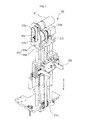
- FIG. 5 is a perspective view of the transfer apparatus 370.
- FIG. 6 is an exploded perspective view of a critical part of the transfer apparatus 370.
- the transfer apparatus 370 includes a drive motor 371, a drive pulley 372a, a driven pulley 372b, a drive belt 373, a drive shaft 374, a first pulley 375a, a second pulley 375b, a switch belt 376, a coupling member 378 and a clutch 379.
- the drive motor 371 serves as a drive source which provides drive force for moving the pressing member 360.
- the drive pulley 372a is rotated by the operation of the drive motor 371.
- the driven pulley 372b is coupled to a first end of the drive shaft 374.
- the drive belt 373 rotates around the drive pulley 372a and the driven pulley 372b which are turning points.
- the first end of the drive shaft 374 is coupled to the driven pulley 372b, and a second end thereof is supported by a bearing B.
- the first pulley 375a is selectively interlocked with the drive shaft 374.
- the first pulley 375a may be interlocked with the drive shaft 372 and rotated along with it, or the first pulley 375a may be released from the drive shaft 372.
- the second pulley 375b is disposed at a position spaced apart from the first pulley 375a by a predetermined distance with respect to a direction in which the pressing member 360 linearly moves.
- the switch belt 376 rotates around the first pulley 375a and the second pulley 375b that function as turning points.
- the first pulley 375a, the second pulley 375b and the switch belt 376 are parts which convert the rotation of the drive shaft 374 into a linear motion of the pressing member 360.
- the coupling member 378 is coupled at a first side thereof to the switch belt 376.
- a second side of the coupling member 378 is coupled to the pressing member 360. Therefore, when the switch belt 376 is rotated, the coupling member 378 and the pressing member 360 move linearly.
- the clutch 379 has an effect of making the first pulley 375a selectively dependent on the rotation of the drive shaft 374.
- the clutch 379 includes a first flange 379a and a second flange 379b.
- the first flange 379a is coupled to the drive shaft 374 and rotated along with the drive shaft 374.
- the first flange 379a comprises an electromagnet which generates magnetic force when power is supplied thereto.
- the second flange 379b is coupled to the first flange 379a by magnetic force.
- the second flange 379b is coupled to the first pulley 375a. Therefore, when the first flange 379a is magnetically coupled to the second flange 379b, the first pulley 375a becomes dependent on the rotation of the drive shaft 374.
- the second flange 379b comprise an electromagnet, when necessary.
- FIG. 7 is a sectional view showing the second flange 379b that has been magnetically coupled to the first flange 379a.
- the drive force of the drive motor 371 is transmitted to the pressing member 360 via the drive pulley 372a, the drive belt 373, the driven pulley 372b, the drive shaft 374, the first flange 379a, the second flange 379b, the first pulley 375a, the switch belt 376 and the coupling member 378, successively.
- the pressing member 360 linearly moves between the generator 330 and the detector 340 upwards or downwards.
- the magnetic force of the first flange 379a is removed.
- the second flange 379b is separated from the first flange 379a.
- the first pulley 375a is released from the drive shaft 374.
- the pressing member 360 that has been pressing the breast of the patient releases the breast.
- a first portion of the drive shaft 374 is fixed to the first flange 379a, while a second portion thereof passes through the second flange 379b and first pulley 375a with a predetermined space defined therebetween.
- the end of the second portion of the drive shaft 374 is supported by the bearing B.
- the reason that magnetic force is used to couple the first flange 379a to the second flange 379b is because excessive pressure must not be applied to the breast of the patient.
- the detector 340 has been illustrated as supporting the breast of the patient, a separate support may be used to support the breast.
- timing belts are used as the drive belt 373 and the switch belt 376 to enhance the precision of transmission of power.
- timing pulleys are preferably used as the drive pulley 372a, the driven pulley 372b, the first pulley 375a and the second pulley 375b.
- a drive belt or switch belt can be prevented from being biased to one side. Therefore, the present invention can minimize problems such as abnormal noise, thus enhancing the reliability of the product.
Landscapes
- Health & Medical Sciences (AREA)
- Life Sciences & Earth Sciences (AREA)
- Engineering & Computer Science (AREA)
- Medical Informatics (AREA)
- Physics & Mathematics (AREA)
- Heart & Thoracic Surgery (AREA)
- Surgery (AREA)
- Nuclear Medicine, Radiotherapy & Molecular Imaging (AREA)
- Optics & Photonics (AREA)
- Pathology (AREA)
- Radiology & Medical Imaging (AREA)
- Biomedical Technology (AREA)
- Biophysics (AREA)
- Molecular Biology (AREA)
- High Energy & Nuclear Physics (AREA)
- Animal Behavior & Ethology (AREA)
- General Health & Medical Sciences (AREA)
- Public Health (AREA)
- Veterinary Medicine (AREA)
- General Engineering & Computer Science (AREA)
- Dentistry (AREA)
- Oral & Maxillofacial Surgery (AREA)
- Electromagnetism (AREA)
- Mechanical Engineering (AREA)
- Apparatus For Radiation Diagnosis (AREA)
Abstract
Description
- This application claims the benefit of Korean Application No.
10-2012-0142547, filed on December 10, 2012 - The present invention relates to X-ray photography machines and, more particularly, to an X-ray photography machine that uses mammography.
- X-ray photography is used in a variety of medical fields.
- A mammography machine is a kind of X-ray photography machine which is used to detect breast cancer, lesions, microcalcification, etc. A representative conventional mammography machine was proposed in Korean Patent Laid-open Publication No.
10-2009-0112992 - To examine the breast of a patient, the breast that is to be examined must be pressed. Thus, mammography machines include a pressing member which presses the breast, and a transfer apparatus which moves the pressing member.
- Typically, when the pressing member presses the breast, the patient feels pain and discomfort. Particularly, if an unexpected event such as power failure occurs, the pressing member may be stopped while the breast is being pressed by the pressing member. In this case, the patient will almost certainly experience a sense of fear or embarrassment. Therefore, when an unexpected event occurs, the pressing member must be able to release the breast.
-
FIG. 1 is a sectional view illustrating a conventional transfer apparatus (at present, unpublished) for mammography machines which was proposed by the applicant of the present invention. This transfer apparatus is configured such that, upon power interruption, a breast pressing operation is automatically stopped so as to release the breast of a patient. - The
transfer apparatus 170 ofFIG. 1 includes adrive motor 171, adrive pulley 172a, a drivenpulley 172b, adrive belt 173, afirst drive shaft 174, afirst pulley 175a, asecond pulley 175b, aswitch belt 176, asecond drive shaft 177, acoupling member 178 and aclutch 179. - The
first drive shaft 174 is interlocked with thedrive pulley 172a, the drivenpulley 172b and thedrive belt 173. - The
second drive shaft 177 is interlocked with thefirst pulley 175a, thesecond pulley 175b and theswitch belt 176. - The
coupling member 178 is coupled at a first side thereof to theswitch belt 176. A second side of thecoupling member 178 is coupled to a pressing member. - The
clutch 179 has an effect of making thesecond drive shaft 177 dependent on the rotation of thefirst drive shaft 174. For this, theclutch 179 includes afirst flange 179a which is interlocked with thefirst drive shaft 174, and asecond flange 179b which is interlocked with thesecond drive shaft 177. - The
first flange 179a generates magnetic force when power is supplied thereto. Thus, upon power being supplied, thesecond flange 179b is attached to thefirst flange 179a by the magnetic force of thefirst flange 179a. In this case, thesecond flange 179b can be rotated in conjunction with the rotation of thefirst flange 179a. - When the power is interrupted, the magnetic force of the
first flange 179a is removed. Then, thesecond flange 179b is separated from thefirst flange 179a. As a result, the pressing member that has been pressing the breast of the patient automatically releases the breast. - Meanwhile, as shown in
FIG. 2 , the tension T1 of thedrive belt 173 and the tension T2 of theswitch belt 176 respectively act as rotation momentum R1 to thefirst drive shaft 174 and as rotation momentum R2 to thesecond drive shaft 177. Thereby, thefirst drive shaft 174 rotates around a first bearing B1 within an allowance range (based on a tolerance or the like). Thesecond drive shaft 177 rotates around a second bearing B2 within an allowance range (based on a tolerance or the like). Therefore, the rotating axes of thefirst drive shaft 174 and thesecond drive shaft 177 may be misaligned with each other rather than being parallel to each other. As a result, thedrive belt 173 and theswitch belt 176 may be biased to one side (refer to the arrows a and b ofFIG. 2 ). If thedrive belt 173 or theswitch belt 176 that has been biased to one side makes contact with a flange portion H1 or H2 of thepulley drive belt 173, theswitch belt 176 and other elements may also be reduced. - Accordingly, the present invention has been made keeping in mind the above problems occurring in the prior art, and an object of the present invention is to provide an X-ray photography machine which, despite using only a single drive shaft, is configured such that when supply of power is interrupted, a target that has been in a pressed state can be released.
- In order to accomplish the above object, the present invention provides an X-ray photography machine, including: a generator emitting an X-ray onto a target; a detector sensing the X-ray that has penetrated the target; a pressing member disposed between the generator and the detector; and a transfer apparatus moving the pressing member towards or away from the detector, the transfer apparatus having a drive source for providing a rotational force, a drive shaft rotated by the rotational force, a first flange fitted on the drive shaft, a second flange provided around the drive shaft with a space defined therebetween, the second flange being selectively coupled to the first flange, and a switch belt connected to the second flange, with the pressing member fastened to the switch belt.
- The above and other objects, features and advantages of the present invention will be more clearly understood from the following detailed description taken in conjunction with the accompanying drawings, in which:
-
FIGS. 1 and2 are sectional views of a transfer apparatus according to a conventional technique; -
FIGS. 3 and4 are perspective views illustrating a mammography machine, according to an embodiment of the present invention; -
FIG. 5 is a perspective view of a transfer apparatus used in the mammography machine ofFIG. 4 ; -
FIG. 6 is an exploded perspective view of a critical part of the transfer apparatus ofFIG. 5 ; and -
FIGS. 7 and8 are sectional views of the critical part of the transfer apparatus ofFIG. 5 . - Hereinafter, a preferred embodiment of the present invention will be described in detail with reference to the attached drawings.
- For the sake of brevity, some explanation will be omitted or condensed if it is overlapping explanation or is not related to the characteristics of the present invention.
-
FIG. 3 is a perspective view of amammography machine 300 according to an embodiment of the present invention. - The
mammography machine 300 includes acolumn 310, a C-shaped arm 320, agenerator 330, adetector 340, apressing member 360 and a transfer apparatus (370, refer toFIG. 4 ). - The
column 310 supports the C-shaped arm 320. - The
generator 330, thedetector 340, thepressing member 360 and thetransfer apparatus 370 are installed in or on the C-shaped arm 320. The C-shaped arm 320 is supported by thecolumn 310 so as to be rotatable or liftable. - The
generator 330 emits X-rays towards thedetector 340. - The
detector 340 senses X-rays which penetrate the breast of a patient that is being examined. - The
pressing member 360 is disposed between thegenerator 330 and thedetector 340. Thepressing member 360 linearly moves between thegenerator 330 and thedetector 340 and presses the patient's breast that has been placed on thedetector 340. - As shown in
FIG. 4 , thetransfer apparatus 370 is installed in an internal space of the C-shaped arm 320. Thetransfer apparatus 370 moves thepressing member 360.FIG. 5 is a perspective view of thetransfer apparatus 370.FIG. 6 is an exploded perspective view of a critical part of thetransfer apparatus 370. Thetransfer apparatus 370 includes adrive motor 371, adrive pulley 372a, a drivenpulley 372b, adrive belt 373, adrive shaft 374, afirst pulley 375a, asecond pulley 375b, aswitch belt 376, acoupling member 378 and aclutch 379. - The
drive motor 371 serves as a drive source which provides drive force for moving thepressing member 360. - The
drive pulley 372a is rotated by the operation of thedrive motor 371. - The driven
pulley 372b is coupled to a first end of thedrive shaft 374. - The
drive belt 373 rotates around thedrive pulley 372a and the drivenpulley 372b which are turning points. - The first end of the
drive shaft 374 is coupled to the drivenpulley 372b, and a second end thereof is supported by a bearing B. - Therefore, when the
drive motor 371 is operated, thedrive pulley 372a, the drivenpulley 372b and thedrive shaft 374 are rotated in conjunction with each other. - The
first pulley 375a is selectively interlocked with thedrive shaft 374. In other words, thefirst pulley 375a may be interlocked with the drive shaft 372 and rotated along with it, or thefirst pulley 375a may be released from the drive shaft 372. - The
second pulley 375b is disposed at a position spaced apart from thefirst pulley 375a by a predetermined distance with respect to a direction in which thepressing member 360 linearly moves. - The
switch belt 376 rotates around thefirst pulley 375a and thesecond pulley 375b that function as turning points. - The
first pulley 375a, thesecond pulley 375b and theswitch belt 376 are parts which convert the rotation of thedrive shaft 374 into a linear motion of thepressing member 360. - The
coupling member 378 is coupled at a first side thereof to theswitch belt 376. A second side of thecoupling member 378 is coupled to thepressing member 360. Therefore, when theswitch belt 376 is rotated, thecoupling member 378 and thepressing member 360 move linearly. - The clutch 379 has an effect of making the
first pulley 375a selectively dependent on the rotation of thedrive shaft 374. For this, the clutch 379 includes afirst flange 379a and asecond flange 379b. - The
first flange 379a is coupled to thedrive shaft 374 and rotated along with thedrive shaft 374. Thefirst flange 379a comprises an electromagnet which generates magnetic force when power is supplied thereto. - The
second flange 379b is coupled to thefirst flange 379a by magnetic force. Thesecond flange 379b is coupled to thefirst pulley 375a. Therefore, when thefirst flange 379a is magnetically coupled to thesecond flange 379b, thefirst pulley 375a becomes dependent on the rotation of thedrive shaft 374. - Of course, it is also preferable that the
second flange 379b comprise an electromagnet, when necessary. -
FIG. 7 is a sectional view showing thesecond flange 379b that has been magnetically coupled to thefirst flange 379a. - In the state of
FIG. 7 , the drive force of thedrive motor 371 is transmitted to thepressing member 360 via thedrive pulley 372a, thedrive belt 373, the drivenpulley 372b, thedrive shaft 374, thefirst flange 379a, thesecond flange 379b, thefirst pulley 375a, theswitch belt 376 and thecoupling member 378, successively. Depending on whether thedrive motor 371 rotates in the normal direction or rotates reversely, the pressingmember 360 linearly moves between thegenerator 330 and thedetector 340 upwards or downwards. - If the supply of power to the
first flange 379a is interrupted by manipulation of an operator or an unexpected event such as power failure, the magnetic force of thefirst flange 379a is removed. Eventually, as shown in an enlarged view ofFIG. 8 , thesecond flange 379b is separated from thefirst flange 379a. - In the state of
FIG. 8 , thefirst pulley 375a is released from thedrive shaft 374. Thereby, the pressingmember 360 that has been pressing the breast of the patient releases the breast. For this, a first portion of thedrive shaft 374 is fixed to thefirst flange 379a, while a second portion thereof passes through thesecond flange 379b andfirst pulley 375a with a predetermined space defined therebetween. The end of the second portion of thedrive shaft 374 is supported by the bearing B. - Meanwhile, the reason that magnetic force is used to couple the
first flange 379a to thesecond flange 379b is because excessive pressure must not be applied to the breast of the patient. - Furthermore, in the above-mentioned embodiment, although the
detector 340 has been illustrated as supporting the breast of the patient, a separate support may be used to support the breast. - Preferably, timing belts are used as the
drive belt 373 and theswitch belt 376 to enhance the precision of transmission of power. Also, timing pulleys are preferably used as thedrive pulley 372a, the drivenpulley 372b, thefirst pulley 375a and thesecond pulley 375b. - As described above, in an X-ray photography machine according to the present invention, a drive belt or switch belt can be prevented from being biased to one side. Therefore, the present invention can minimize problems such as abnormal noise, thus enhancing the reliability of the product.
- Although the preferred embodiment of the present invention has been disclosed for illustrative purposes, those skilled in the art will appreciate that various modifications, additions and substitutions are possible, without departing from the scope and spirit of the invention as disclosed in the accompanying claims.
Claims (5)
- An X-ray photography machine, comprising:a generator emitting an X-ray onto a target;a detector sensing the X-ray that has penetrated the target;a pressing member disposed between the generator and the detector; anda transfer apparatus moving the pressing member towards or away from the detector, the transfer apparatus comprising:a drive source for providing a rotational force;a drive shaft rotated by the rotational force;a first flange fitted on the drive shaft;a second flange provided around the drive shaft with a space defined therebetween, the second flange being selectively coupled to the first flange; anda switch belt connected to the second flange, with the pressing member fastened to the switch belt.
- The X-ray photography machine as set forth in claim 1, wherein either the first flange or the second flange selectively generates a magnetic force depending on supply of power, and a remaining one of the first flange and the second flange is magnetically coupled to the either the first flange or the second flange.
- The X-ray photography machine as set forth in claim 1, further comprising
a first pulley provided around the drive shaft with a space defined therebetween, the first pulley being coupled to the second flange,
wherein the switch belt is connected to the first pulley. - The X-ray photography machine as set forth in claim 3, further comprising
a second pulley spaced apart from a first pulley by a predetermined distance with respect to a direction in which the pressing member moves,
wherein the switch belt connects the first pulley to the second pulley. - The X-ray photography machine as set forth in claim 3, further comprising:a drive pulley connected to the drive source;a driven pulley coupled to the drive shaft; anda drive belt connecting the drive pulley to the driven pulley.
Applications Claiming Priority (1)
| Application Number | Priority Date | Filing Date | Title |
|---|---|---|---|
| KR1020120142547A KR101377127B1 (en) | 2012-12-10 | 2012-12-10 | X-ray photographing apparatus |
Publications (2)
| Publication Number | Publication Date |
|---|---|
| EP2740406A1 true EP2740406A1 (en) | 2014-06-11 |
| EP2740406B1 EP2740406B1 (en) | 2019-06-12 |
Family
ID=47627964
Family Applications (1)
| Application Number | Title | Priority Date | Filing Date |
|---|---|---|---|
| EP13150045.6A Active EP2740406B1 (en) | 2012-12-10 | 2013-01-02 | X-ray photography machine |
Country Status (2)
| Country | Link |
|---|---|
| EP (1) | EP2740406B1 (en) |
| KR (1) | KR101377127B1 (en) |
Cited By (3)
| Publication number | Priority date | Publication date | Assignee | Title |
|---|---|---|---|---|
| CN105640580A (en) * | 2016-02-29 | 2016-06-08 | 江苏美伦影像系统有限公司 | Rotary structure applicable to oral cavity CT |
| EP3238628A4 (en) * | 2014-12-26 | 2018-08-15 | Rayence Co., Ltd. | Lifting apparatus for pressure paddle and x-ray image photographing device including same |
| EP3845129A1 (en) * | 2020-01-06 | 2021-07-07 | Vieworks Co., Ltd. | Mammography device |
Citations (4)
| Publication number | Priority date | Publication date | Assignee | Title |
|---|---|---|---|---|
| US4658409A (en) * | 1983-11-04 | 1987-04-14 | Siemens Aktiengesellschaft | Compression device for an X-ray diagnostic apparatus |
| US20090143146A1 (en) * | 2007-11-28 | 2009-06-04 | Robert Standar | Clutch and mammography device |
| KR20090112992A (en) | 2008-04-25 | 2009-10-29 | 주식회사바텍 | Mammography with large area digital sensor |
| US20120136234A1 (en) * | 2010-11-29 | 2012-05-31 | Canon Kabushiki Kaisha | Apparatus |
Family Cites Families (3)
| Publication number | Priority date | Publication date | Assignee | Title |
|---|---|---|---|---|
| FR2829918A1 (en) | 2001-09-25 | 2003-03-28 | Ge Med Sys Global Tech Co Llc | Imaging method in mammography apparatus, involves moving compression paddle in compression position, in projection to different directions perpendicular to X-ray propagation direction |
| JP4970065B2 (en) | 2006-01-31 | 2012-07-04 | 株式会社東芝 | Mammography device |
| JP2010110571A (en) | 2008-11-10 | 2010-05-20 | Fujifilm Corp | Photographic equipment and mammography device |
-
2012
- 2012-12-10 KR KR1020120142547A patent/KR101377127B1/en not_active Expired - Fee Related
-
2013
- 2013-01-02 EP EP13150045.6A patent/EP2740406B1/en active Active
Patent Citations (4)
| Publication number | Priority date | Publication date | Assignee | Title |
|---|---|---|---|---|
| US4658409A (en) * | 1983-11-04 | 1987-04-14 | Siemens Aktiengesellschaft | Compression device for an X-ray diagnostic apparatus |
| US20090143146A1 (en) * | 2007-11-28 | 2009-06-04 | Robert Standar | Clutch and mammography device |
| KR20090112992A (en) | 2008-04-25 | 2009-10-29 | 주식회사바텍 | Mammography with large area digital sensor |
| US20120136234A1 (en) * | 2010-11-29 | 2012-05-31 | Canon Kabushiki Kaisha | Apparatus |
Cited By (5)
| Publication number | Priority date | Publication date | Assignee | Title |
|---|---|---|---|---|
| EP3238628A4 (en) * | 2014-12-26 | 2018-08-15 | Rayence Co., Ltd. | Lifting apparatus for pressure paddle and x-ray image photographing device including same |
| US10631809B2 (en) | 2014-12-26 | 2020-04-28 | Rayence Co., Ltd. | Lifting device for compression paddle and X-ray imaging apparatus including the same |
| CN105640580A (en) * | 2016-02-29 | 2016-06-08 | 江苏美伦影像系统有限公司 | Rotary structure applicable to oral cavity CT |
| EP3845129A1 (en) * | 2020-01-06 | 2021-07-07 | Vieworks Co., Ltd. | Mammography device |
| US11266367B2 (en) | 2020-01-06 | 2022-03-08 | Vieworks Co., Ltd. | Mammography device |
Also Published As
| Publication number | Publication date |
|---|---|
| KR101377127B1 (en) | 2014-03-25 |
| EP2740406B1 (en) | 2019-06-12 |
Similar Documents
| Publication | Publication Date | Title |
|---|---|---|
| US9492128B2 (en) | X-ray photography machine with selectively coupled flanges for pressing member movement | |
| US10987491B2 (en) | Robotic catheter system | |
| EP2668903B1 (en) | Photographing device including a power transmission body selectively coupled to a rotating arm and to a support | |
| US10583276B2 (en) | Catheter system with magnetic coupling | |
| US8024987B2 (en) | Linear actuator | |
| CN101011249A (en) | X-ray mammographic apparatus | |
| EP2740406A1 (en) | X-ray photography machine | |
| KR101454082B1 (en) | X-ray photographing apparatus | |
| US10888289B2 (en) | Mammography apparatus | |
| JP5676358B2 (en) | Radiography equipment |
Legal Events
| Date | Code | Title | Description |
|---|---|---|---|
| PUAI | Public reference made under article 153(3) epc to a published international application that has entered the european phase |
Free format text: ORIGINAL CODE: 0009012 |
|
| 17P | Request for examination filed |
Effective date: 20130102 |
|
| AK | Designated contracting states |
Kind code of ref document: A1 Designated state(s): AL AT BE BG CH CY CZ DE DK EE ES FI FR GB GR HR HU IE IS IT LI LT LU LV MC MK MT NL NO PL PT RO RS SE SI SK SM TR |
|
| AX | Request for extension of the european patent |
Extension state: BA ME |
|
| R17P | Request for examination filed (corrected) |
Effective date: 20141211 |
|
| RBV | Designated contracting states (corrected) |
Designated state(s): AL AT BE BG CH CY CZ DE DK EE ES FI FR GB GR HR HU IE IS IT LI LT LU LV MC MK MT NL NO PL PT RO RS SE SI SK SM TR |
|
| RAP1 | Party data changed (applicant data changed or rights of an application transferred) |
Owner name: GENERAL ELECTRIC COMPANY |
|
| STAA | Information on the status of an ep patent application or granted ep patent |
Free format text: STATUS: EXAMINATION IS IN PROGRESS |
|
| 17Q | First examination report despatched |
Effective date: 20171106 |
|
| GRAP | Despatch of communication of intention to grant a patent |
Free format text: ORIGINAL CODE: EPIDOSNIGR1 |
|
| STAA | Information on the status of an ep patent application or granted ep patent |
Free format text: STATUS: GRANT OF PATENT IS INTENDED |
|
| INTG | Intention to grant announced |
Effective date: 20190104 |
|
| GRAS | Grant fee paid |
Free format text: ORIGINAL CODE: EPIDOSNIGR3 |
|
| GRAA | (expected) grant |
Free format text: ORIGINAL CODE: 0009210 |
|
| STAA | Information on the status of an ep patent application or granted ep patent |
Free format text: STATUS: THE PATENT HAS BEEN GRANTED |
|
| AK | Designated contracting states |
Kind code of ref document: B1 Designated state(s): AL AT BE BG CH CY CZ DE DK EE ES FI FR GB GR HR HU IE IS IT LI LT LU LV MC MK MT NL NO PL PT RO RS SE SI SK SM TR |
|
| REG | Reference to a national code |
Ref country code: GB Ref legal event code: FG4D |
|
| REG | Reference to a national code |
Ref country code: CH Ref legal event code: EP |
|
| REG | Reference to a national code |
Ref country code: AT Ref legal event code: REF Ref document number: 1141527 Country of ref document: AT Kind code of ref document: T Effective date: 20190615 |
|
| REG | Reference to a national code |
Ref country code: DE Ref legal event code: R096 Ref document number: 602013056393 Country of ref document: DE |
|
| REG | Reference to a national code |
Ref country code: IE Ref legal event code: FG4D |
|
| REG | Reference to a national code |
Ref country code: NL Ref legal event code: MP Effective date: 20190612 |
|
| REG | Reference to a national code |
Ref country code: LT Ref legal event code: MG4D |
|
| PG25 | Lapsed in a contracting state [announced via postgrant information from national office to epo] |
Ref country code: SE Free format text: LAPSE BECAUSE OF FAILURE TO SUBMIT A TRANSLATION OF THE DESCRIPTION OR TO PAY THE FEE WITHIN THE PRESCRIBED TIME-LIMIT Effective date: 20190612 Ref country code: LT Free format text: LAPSE BECAUSE OF FAILURE TO SUBMIT A TRANSLATION OF THE DESCRIPTION OR TO PAY THE FEE WITHIN THE PRESCRIBED TIME-LIMIT Effective date: 20190612 Ref country code: AL Free format text: LAPSE BECAUSE OF FAILURE TO SUBMIT A TRANSLATION OF THE DESCRIPTION OR TO PAY THE FEE WITHIN THE PRESCRIBED TIME-LIMIT Effective date: 20190612 Ref country code: HR Free format text: LAPSE BECAUSE OF FAILURE TO SUBMIT A TRANSLATION OF THE DESCRIPTION OR TO PAY THE FEE WITHIN THE PRESCRIBED TIME-LIMIT Effective date: 20190612 Ref country code: NO Free format text: LAPSE BECAUSE OF FAILURE TO SUBMIT A TRANSLATION OF THE DESCRIPTION OR TO PAY THE FEE WITHIN THE PRESCRIBED TIME-LIMIT Effective date: 20190912 Ref country code: FI Free format text: LAPSE BECAUSE OF FAILURE TO SUBMIT A TRANSLATION OF THE DESCRIPTION OR TO PAY THE FEE WITHIN THE PRESCRIBED TIME-LIMIT Effective date: 20190612 |
|
| PG25 | Lapsed in a contracting state [announced via postgrant information from national office to epo] |
Ref country code: GR Free format text: LAPSE BECAUSE OF FAILURE TO SUBMIT A TRANSLATION OF THE DESCRIPTION OR TO PAY THE FEE WITHIN THE PRESCRIBED TIME-LIMIT Effective date: 20190913 Ref country code: BG Free format text: LAPSE BECAUSE OF FAILURE TO SUBMIT A TRANSLATION OF THE DESCRIPTION OR TO PAY THE FEE WITHIN THE PRESCRIBED TIME-LIMIT Effective date: 20190912 Ref country code: RS Free format text: LAPSE BECAUSE OF FAILURE TO SUBMIT A TRANSLATION OF THE DESCRIPTION OR TO PAY THE FEE WITHIN THE PRESCRIBED TIME-LIMIT Effective date: 20190612 Ref country code: LV Free format text: LAPSE BECAUSE OF FAILURE TO SUBMIT A TRANSLATION OF THE DESCRIPTION OR TO PAY THE FEE WITHIN THE PRESCRIBED TIME-LIMIT Effective date: 20190612 |
|
| REG | Reference to a national code |
Ref country code: AT Ref legal event code: MK05 Ref document number: 1141527 Country of ref document: AT Kind code of ref document: T Effective date: 20190612 |
|
| PG25 | Lapsed in a contracting state [announced via postgrant information from national office to epo] |
Ref country code: AT Free format text: LAPSE BECAUSE OF FAILURE TO SUBMIT A TRANSLATION OF THE DESCRIPTION OR TO PAY THE FEE WITHIN THE PRESCRIBED TIME-LIMIT Effective date: 20190612 Ref country code: EE Free format text: LAPSE BECAUSE OF FAILURE TO SUBMIT A TRANSLATION OF THE DESCRIPTION OR TO PAY THE FEE WITHIN THE PRESCRIBED TIME-LIMIT Effective date: 20190612 Ref country code: SK Free format text: LAPSE BECAUSE OF FAILURE TO SUBMIT A TRANSLATION OF THE DESCRIPTION OR TO PAY THE FEE WITHIN THE PRESCRIBED TIME-LIMIT Effective date: 20190612 Ref country code: PT Free format text: LAPSE BECAUSE OF FAILURE TO SUBMIT A TRANSLATION OF THE DESCRIPTION OR TO PAY THE FEE WITHIN THE PRESCRIBED TIME-LIMIT Effective date: 20191014 Ref country code: RO Free format text: LAPSE BECAUSE OF FAILURE TO SUBMIT A TRANSLATION OF THE DESCRIPTION OR TO PAY THE FEE WITHIN THE PRESCRIBED TIME-LIMIT Effective date: 20190612 Ref country code: NL Free format text: LAPSE BECAUSE OF FAILURE TO SUBMIT A TRANSLATION OF THE DESCRIPTION OR TO PAY THE FEE WITHIN THE PRESCRIBED TIME-LIMIT Effective date: 20190612 Ref country code: CZ Free format text: LAPSE BECAUSE OF FAILURE TO SUBMIT A TRANSLATION OF THE DESCRIPTION OR TO PAY THE FEE WITHIN THE PRESCRIBED TIME-LIMIT Effective date: 20190612 |
|
| PG25 | Lapsed in a contracting state [announced via postgrant information from national office to epo] |
Ref country code: IS Free format text: LAPSE BECAUSE OF FAILURE TO SUBMIT A TRANSLATION OF THE DESCRIPTION OR TO PAY THE FEE WITHIN THE PRESCRIBED TIME-LIMIT Effective date: 20191012 Ref country code: ES Free format text: LAPSE BECAUSE OF FAILURE TO SUBMIT A TRANSLATION OF THE DESCRIPTION OR TO PAY THE FEE WITHIN THE PRESCRIBED TIME-LIMIT Effective date: 20190612 Ref country code: IT Free format text: LAPSE BECAUSE OF FAILURE TO SUBMIT A TRANSLATION OF THE DESCRIPTION OR TO PAY THE FEE WITHIN THE PRESCRIBED TIME-LIMIT Effective date: 20190612 Ref country code: SM Free format text: LAPSE BECAUSE OF FAILURE TO SUBMIT A TRANSLATION OF THE DESCRIPTION OR TO PAY THE FEE WITHIN THE PRESCRIBED TIME-LIMIT Effective date: 20190612 |
|
| REG | Reference to a national code |
Ref country code: DE Ref legal event code: R097 Ref document number: 602013056393 Country of ref document: DE |
|
| PG25 | Lapsed in a contracting state [announced via postgrant information from national office to epo] |
Ref country code: TR Free format text: LAPSE BECAUSE OF FAILURE TO SUBMIT A TRANSLATION OF THE DESCRIPTION OR TO PAY THE FEE WITHIN THE PRESCRIBED TIME-LIMIT Effective date: 20190612 |
|
| PLBE | No opposition filed within time limit |
Free format text: ORIGINAL CODE: 0009261 |
|
| STAA | Information on the status of an ep patent application or granted ep patent |
Free format text: STATUS: NO OPPOSITION FILED WITHIN TIME LIMIT |
|
| PG25 | Lapsed in a contracting state [announced via postgrant information from national office to epo] |
Ref country code: PL Free format text: LAPSE BECAUSE OF FAILURE TO SUBMIT A TRANSLATION OF THE DESCRIPTION OR TO PAY THE FEE WITHIN THE PRESCRIBED TIME-LIMIT Effective date: 20190612 Ref country code: DK Free format text: LAPSE BECAUSE OF FAILURE TO SUBMIT A TRANSLATION OF THE DESCRIPTION OR TO PAY THE FEE WITHIN THE PRESCRIBED TIME-LIMIT Effective date: 20190612 |
|
| 26N | No opposition filed |
Effective date: 20200313 |
|
| PG25 | Lapsed in a contracting state [announced via postgrant information from national office to epo] |
Ref country code: IS Free format text: LAPSE BECAUSE OF FAILURE TO SUBMIT A TRANSLATION OF THE DESCRIPTION OR TO PAY THE FEE WITHIN THE PRESCRIBED TIME-LIMIT Effective date: 20200224 Ref country code: SI Free format text: LAPSE BECAUSE OF FAILURE TO SUBMIT A TRANSLATION OF THE DESCRIPTION OR TO PAY THE FEE WITHIN THE PRESCRIBED TIME-LIMIT Effective date: 20190612 |
|
| PG2D | Information on lapse in contracting state deleted |
Ref country code: IS |
|
| PG25 | Lapsed in a contracting state [announced via postgrant information from national office to epo] |
Ref country code: MC Free format text: LAPSE BECAUSE OF FAILURE TO SUBMIT A TRANSLATION OF THE DESCRIPTION OR TO PAY THE FEE WITHIN THE PRESCRIBED TIME-LIMIT Effective date: 20190612 |
|
| REG | Reference to a national code |
Ref country code: CH Ref legal event code: PL |
|
| REG | Reference to a national code |
Ref country code: BE Ref legal event code: MM Effective date: 20200131 |
|
| PG25 | Lapsed in a contracting state [announced via postgrant information from national office to epo] |
Ref country code: FR Free format text: LAPSE BECAUSE OF NON-PAYMENT OF DUE FEES Effective date: 20200131 Ref country code: LU Free format text: LAPSE BECAUSE OF NON-PAYMENT OF DUE FEES Effective date: 20200102 |
|
| PG25 | Lapsed in a contracting state [announced via postgrant information from national office to epo] |
Ref country code: BE Free format text: LAPSE BECAUSE OF NON-PAYMENT OF DUE FEES Effective date: 20200131 Ref country code: CH Free format text: LAPSE BECAUSE OF NON-PAYMENT OF DUE FEES Effective date: 20200131 Ref country code: LI Free format text: LAPSE BECAUSE OF NON-PAYMENT OF DUE FEES Effective date: 20200131 |
|
| PG25 | Lapsed in a contracting state [announced via postgrant information from national office to epo] |
Ref country code: IE Free format text: LAPSE BECAUSE OF NON-PAYMENT OF DUE FEES Effective date: 20200102 |
|
| PGFP | Annual fee paid to national office [announced via postgrant information from national office to epo] |
Ref country code: GB Payment date: 20211216 Year of fee payment: 10 |
|
| PGFP | Annual fee paid to national office [announced via postgrant information from national office to epo] |
Ref country code: DE Payment date: 20211215 Year of fee payment: 10 |
|
| PG25 | Lapsed in a contracting state [announced via postgrant information from national office to epo] |
Ref country code: MT Free format text: LAPSE BECAUSE OF FAILURE TO SUBMIT A TRANSLATION OF THE DESCRIPTION OR TO PAY THE FEE WITHIN THE PRESCRIBED TIME-LIMIT Effective date: 20190612 Ref country code: CY Free format text: LAPSE BECAUSE OF FAILURE TO SUBMIT A TRANSLATION OF THE DESCRIPTION OR TO PAY THE FEE WITHIN THE PRESCRIBED TIME-LIMIT Effective date: 20190612 |
|
| PG25 | Lapsed in a contracting state [announced via postgrant information from national office to epo] |
Ref country code: MK Free format text: LAPSE BECAUSE OF FAILURE TO SUBMIT A TRANSLATION OF THE DESCRIPTION OR TO PAY THE FEE WITHIN THE PRESCRIBED TIME-LIMIT Effective date: 20190612 |
|
| REG | Reference to a national code |
Ref country code: DE Ref legal event code: R119 Ref document number: 602013056393 Country of ref document: DE |
|
| GBPC | Gb: european patent ceased through non-payment of renewal fee |
Effective date: 20230102 |
|
| PG25 | Lapsed in a contracting state [announced via postgrant information from national office to epo] |
Ref country code: GB Free format text: LAPSE BECAUSE OF NON-PAYMENT OF DUE FEES Effective date: 20230102 Ref country code: DE Free format text: LAPSE BECAUSE OF NON-PAYMENT OF DUE FEES Effective date: 20230801 |