EP2739761B1 - Carbo-nitriding process for martensitic stainless steel and stainless steel article having improved corrosion resistance - Google Patents
Carbo-nitriding process for martensitic stainless steel and stainless steel article having improved corrosion resistance Download PDFInfo
- Publication number
- EP2739761B1 EP2739761B1 EP12792569.1A EP12792569A EP2739761B1 EP 2739761 B1 EP2739761 B1 EP 2739761B1 EP 12792569 A EP12792569 A EP 12792569A EP 2739761 B1 EP2739761 B1 EP 2739761B1
- Authority
- EP
- European Patent Office
- Prior art keywords
- stainless steel
- case
- hardened
- martensitic stainless
- nitrogen
- Prior art date
- Legal status (The legal status is an assumption and is not a legal conclusion. Google has not performed a legal analysis and makes no representation as to the accuracy of the status listed.)
- Active
Links
Images


Classifications
-
- C—CHEMISTRY; METALLURGY
- C23—COATING METALLIC MATERIAL; COATING MATERIAL WITH METALLIC MATERIAL; CHEMICAL SURFACE TREATMENT; DIFFUSION TREATMENT OF METALLIC MATERIAL; COATING BY VACUUM EVAPORATION, BY SPUTTERING, BY ION IMPLANTATION OR BY CHEMICAL VAPOUR DEPOSITION, IN GENERAL; INHIBITING CORROSION OF METALLIC MATERIAL OR INCRUSTATION IN GENERAL
- C23C—COATING METALLIC MATERIAL; COATING MATERIAL WITH METALLIC MATERIAL; SURFACE TREATMENT OF METALLIC MATERIAL BY DIFFUSION INTO THE SURFACE, BY CHEMICAL CONVERSION OR SUBSTITUTION; COATING BY VACUUM EVAPORATION, BY SPUTTERING, BY ION IMPLANTATION OR BY CHEMICAL VAPOUR DEPOSITION, IN GENERAL
- C23C8/00—Solid state diffusion of only non-metal elements into metallic material surfaces; Chemical surface treatment of metallic material by reaction of the surface with a reactive gas, leaving reaction products of surface material in the coating, e.g. conversion coatings, passivation of metals
- C23C8/06—Solid state diffusion of only non-metal elements into metallic material surfaces; Chemical surface treatment of metallic material by reaction of the surface with a reactive gas, leaving reaction products of surface material in the coating, e.g. conversion coatings, passivation of metals using gases
- C23C8/28—Solid state diffusion of only non-metal elements into metallic material surfaces; Chemical surface treatment of metallic material by reaction of the surface with a reactive gas, leaving reaction products of surface material in the coating, e.g. conversion coatings, passivation of metals using gases more than one element being applied in one step
- C23C8/30—Carbo-nitriding
- C23C8/32—Carbo-nitriding of ferrous surfaces
-
- C—CHEMISTRY; METALLURGY
- C21—METALLURGY OF IRON
- C21D—MODIFYING THE PHYSICAL STRUCTURE OF FERROUS METALS; GENERAL DEVICES FOR HEAT TREATMENT OF FERROUS OR NON-FERROUS METALS OR ALLOYS; MAKING METAL MALLEABLE, e.g. BY DECARBURISATION OR TEMPERING
- C21D1/00—General methods or devices for heat treatment, e.g. annealing, hardening, quenching or tempering
- C21D1/06—Surface hardening
-
- C—CHEMISTRY; METALLURGY
- C21—METALLURGY OF IRON
- C21D—MODIFYING THE PHYSICAL STRUCTURE OF FERROUS METALS; GENERAL DEVICES FOR HEAT TREATMENT OF FERROUS OR NON-FERROUS METALS OR ALLOYS; MAKING METAL MALLEABLE, e.g. BY DECARBURISATION OR TEMPERING
- C21D1/00—General methods or devices for heat treatment, e.g. annealing, hardening, quenching or tempering
- C21D1/18—Hardening; Quenching with or without subsequent tempering
- C21D1/25—Hardening, combined with annealing between 300 degrees Celsius and 600 degrees Celsius, i.e. heat refining ("Vergüten")
-
- C—CHEMISTRY; METALLURGY
- C21—METALLURGY OF IRON
- C21D—MODIFYING THE PHYSICAL STRUCTURE OF FERROUS METALS; GENERAL DEVICES FOR HEAT TREATMENT OF FERROUS OR NON-FERROUS METALS OR ALLOYS; MAKING METAL MALLEABLE, e.g. BY DECARBURISATION OR TEMPERING
- C21D6/00—Heat treatment of ferrous alloys
- C21D6/005—Heat treatment of ferrous alloys containing Mn
-
- C—CHEMISTRY; METALLURGY
- C21—METALLURGY OF IRON
- C21D—MODIFYING THE PHYSICAL STRUCTURE OF FERROUS METALS; GENERAL DEVICES FOR HEAT TREATMENT OF FERROUS OR NON-FERROUS METALS OR ALLOYS; MAKING METAL MALLEABLE, e.g. BY DECARBURISATION OR TEMPERING
- C21D6/00—Heat treatment of ferrous alloys
- C21D6/007—Heat treatment of ferrous alloys containing Co
-
- C—CHEMISTRY; METALLURGY
- C21—METALLURGY OF IRON
- C21D—MODIFYING THE PHYSICAL STRUCTURE OF FERROUS METALS; GENERAL DEVICES FOR HEAT TREATMENT OF FERROUS OR NON-FERROUS METALS OR ALLOYS; MAKING METAL MALLEABLE, e.g. BY DECARBURISATION OR TEMPERING
- C21D9/00—Heat treatment, e.g. annealing, hardening, quenching or tempering, adapted for particular articles; Furnaces therefor
- C21D9/40—Heat treatment, e.g. annealing, hardening, quenching or tempering, adapted for particular articles; Furnaces therefor for rings; for bearing races
-
- C—CHEMISTRY; METALLURGY
- C22—METALLURGY; FERROUS OR NON-FERROUS ALLOYS; TREATMENT OF ALLOYS OR NON-FERROUS METALS
- C22C—ALLOYS
- C22C38/00—Ferrous alloys, e.g. steel alloys
- C22C38/02—Ferrous alloys, e.g. steel alloys containing silicon
-
- C—CHEMISTRY; METALLURGY
- C22—METALLURGY; FERROUS OR NON-FERROUS ALLOYS; TREATMENT OF ALLOYS OR NON-FERROUS METALS
- C22C—ALLOYS
- C22C38/00—Ferrous alloys, e.g. steel alloys
- C22C38/04—Ferrous alloys, e.g. steel alloys containing manganese
-
- C—CHEMISTRY; METALLURGY
- C22—METALLURGY; FERROUS OR NON-FERROUS ALLOYS; TREATMENT OF ALLOYS OR NON-FERROUS METALS
- C22C—ALLOYS
- C22C38/00—Ferrous alloys, e.g. steel alloys
- C22C38/18—Ferrous alloys, e.g. steel alloys containing chromium
- C22C38/40—Ferrous alloys, e.g. steel alloys containing chromium with nickel
- C22C38/44—Ferrous alloys, e.g. steel alloys containing chromium with nickel with molybdenum or tungsten
-
- C—CHEMISTRY; METALLURGY
- C22—METALLURGY; FERROUS OR NON-FERROUS ALLOYS; TREATMENT OF ALLOYS OR NON-FERROUS METALS
- C22C—ALLOYS
- C22C38/00—Ferrous alloys, e.g. steel alloys
- C22C38/18—Ferrous alloys, e.g. steel alloys containing chromium
- C22C38/40—Ferrous alloys, e.g. steel alloys containing chromium with nickel
- C22C38/46—Ferrous alloys, e.g. steel alloys containing chromium with nickel with vanadium
-
- C—CHEMISTRY; METALLURGY
- C22—METALLURGY; FERROUS OR NON-FERROUS ALLOYS; TREATMENT OF ALLOYS OR NON-FERROUS METALS
- C22C—ALLOYS
- C22C38/00—Ferrous alloys, e.g. steel alloys
- C22C38/18—Ferrous alloys, e.g. steel alloys containing chromium
- C22C38/40—Ferrous alloys, e.g. steel alloys containing chromium with nickel
- C22C38/48—Ferrous alloys, e.g. steel alloys containing chromium with nickel with niobium or tantalum
-
- C—CHEMISTRY; METALLURGY
- C22—METALLURGY; FERROUS OR NON-FERROUS ALLOYS; TREATMENT OF ALLOYS OR NON-FERROUS METALS
- C22C—ALLOYS
- C22C38/00—Ferrous alloys, e.g. steel alloys
- C22C38/18—Ferrous alloys, e.g. steel alloys containing chromium
- C22C38/40—Ferrous alloys, e.g. steel alloys containing chromium with nickel
- C22C38/52—Ferrous alloys, e.g. steel alloys containing chromium with nickel with cobalt
-
- C—CHEMISTRY; METALLURGY
- C23—COATING METALLIC MATERIAL; COATING MATERIAL WITH METALLIC MATERIAL; CHEMICAL SURFACE TREATMENT; DIFFUSION TREATMENT OF METALLIC MATERIAL; COATING BY VACUUM EVAPORATION, BY SPUTTERING, BY ION IMPLANTATION OR BY CHEMICAL VAPOUR DEPOSITION, IN GENERAL; INHIBITING CORROSION OF METALLIC MATERIAL OR INCRUSTATION IN GENERAL
- C23C—COATING METALLIC MATERIAL; COATING MATERIAL WITH METALLIC MATERIAL; SURFACE TREATMENT OF METALLIC MATERIAL BY DIFFUSION INTO THE SURFACE, BY CHEMICAL CONVERSION OR SUBSTITUTION; COATING BY VACUUM EVAPORATION, BY SPUTTERING, BY ION IMPLANTATION OR BY CHEMICAL VAPOUR DEPOSITION, IN GENERAL
- C23C8/00—Solid state diffusion of only non-metal elements into metallic material surfaces; Chemical surface treatment of metallic material by reaction of the surface with a reactive gas, leaving reaction products of surface material in the coating, e.g. conversion coatings, passivation of metals
- C23C8/40—Solid state diffusion of only non-metal elements into metallic material surfaces; Chemical surface treatment of metallic material by reaction of the surface with a reactive gas, leaving reaction products of surface material in the coating, e.g. conversion coatings, passivation of metals using liquids, e.g. salt baths, liquid suspensions
- C23C8/58—Solid state diffusion of only non-metal elements into metallic material surfaces; Chemical surface treatment of metallic material by reaction of the surface with a reactive gas, leaving reaction products of surface material in the coating, e.g. conversion coatings, passivation of metals using liquids, e.g. salt baths, liquid suspensions more than one element being applied in more than one step
-
- F—MECHANICAL ENGINEERING; LIGHTING; HEATING; WEAPONS; BLASTING
- F16—ENGINEERING ELEMENTS AND UNITS; GENERAL MEASURES FOR PRODUCING AND MAINTAINING EFFECTIVE FUNCTIONING OF MACHINES OR INSTALLATIONS; THERMAL INSULATION IN GENERAL
- F16C—SHAFTS; FLEXIBLE SHAFTS; ELEMENTS OR CRANKSHAFT MECHANISMS; ROTARY BODIES OTHER THAN GEARING ELEMENTS; BEARINGS
- F16C33/00—Parts of bearings; Special methods for making bearings or parts thereof
- F16C33/30—Parts of ball or roller bearings
- F16C33/58—Raceways; Race rings
- F16C33/62—Selection of substances
-
- F—MECHANICAL ENGINEERING; LIGHTING; HEATING; WEAPONS; BLASTING
- F16—ENGINEERING ELEMENTS AND UNITS; GENERAL MEASURES FOR PRODUCING AND MAINTAINING EFFECTIVE FUNCTIONING OF MACHINES OR INSTALLATIONS; THERMAL INSULATION IN GENERAL
- F16C—SHAFTS; FLEXIBLE SHAFTS; ELEMENTS OR CRANKSHAFT MECHANISMS; ROTARY BODIES OTHER THAN GEARING ELEMENTS; BEARINGS
- F16C33/00—Parts of bearings; Special methods for making bearings or parts thereof
- F16C33/30—Parts of ball or roller bearings
- F16C33/58—Raceways; Race rings
- F16C33/64—Special methods of manufacture
-
- C—CHEMISTRY; METALLURGY
- C21—METALLURGY OF IRON
- C21D—MODIFYING THE PHYSICAL STRUCTURE OF FERROUS METALS; GENERAL DEVICES FOR HEAT TREATMENT OF FERROUS OR NON-FERROUS METALS OR ALLOYS; MAKING METAL MALLEABLE, e.g. BY DECARBURISATION OR TEMPERING
- C21D2211/00—Microstructure comprising significant phases
- C21D2211/008—Martensite
-
- C—CHEMISTRY; METALLURGY
- C22—METALLURGY; FERROUS OR NON-FERROUS ALLOYS; TREATMENT OF ALLOYS OR NON-FERROUS METALS
- C22C—ALLOYS
- C22C19/00—Alloys based on nickel or cobalt
- C22C19/03—Alloys based on nickel or cobalt based on nickel
-
- C—CHEMISTRY; METALLURGY
- C22—METALLURGY; FERROUS OR NON-FERROUS ALLOYS; TREATMENT OF ALLOYS OR NON-FERROUS METALS
- C22C—ALLOYS
- C22C5/00—Alloys based on noble metals
- C22C5/04—Alloys based on a platinum group metal
-
- F—MECHANICAL ENGINEERING; LIGHTING; HEATING; WEAPONS; BLASTING
- F16—ENGINEERING ELEMENTS AND UNITS; GENERAL MEASURES FOR PRODUCING AND MAINTAINING EFFECTIVE FUNCTIONING OF MACHINES OR INSTALLATIONS; THERMAL INSULATION IN GENERAL
- F16C—SHAFTS; FLEXIBLE SHAFTS; ELEMENTS OR CRANKSHAFT MECHANISMS; ROTARY BODIES OTHER THAN GEARING ELEMENTS; BEARINGS
- F16C2202/00—Solid materials defined by their properties
- F16C2202/02—Mechanical properties
- F16C2202/04—Hardness
-
- F—MECHANICAL ENGINEERING; LIGHTING; HEATING; WEAPONS; BLASTING
- F16—ENGINEERING ELEMENTS AND UNITS; GENERAL MEASURES FOR PRODUCING AND MAINTAINING EFFECTIVE FUNCTIONING OF MACHINES OR INSTALLATIONS; THERMAL INSULATION IN GENERAL
- F16C—SHAFTS; FLEXIBLE SHAFTS; ELEMENTS OR CRANKSHAFT MECHANISMS; ROTARY BODIES OTHER THAN GEARING ELEMENTS; BEARINGS
- F16C2204/00—Metallic materials; Alloys
- F16C2204/60—Ferrous alloys, e.g. steel alloys
- F16C2204/70—Ferrous alloys, e.g. steel alloys with chromium as the next major constituent
-
- F—MECHANICAL ENGINEERING; LIGHTING; HEATING; WEAPONS; BLASTING
- F16—ENGINEERING ELEMENTS AND UNITS; GENERAL MEASURES FOR PRODUCING AND MAINTAINING EFFECTIVE FUNCTIONING OF MACHINES OR INSTALLATIONS; THERMAL INSULATION IN GENERAL
- F16C—SHAFTS; FLEXIBLE SHAFTS; ELEMENTS OR CRANKSHAFT MECHANISMS; ROTARY BODIES OTHER THAN GEARING ELEMENTS; BEARINGS
- F16C2240/00—Specified values or numerical ranges of parameters; Relations between them
- F16C2240/06—Temperature
-
- F—MECHANICAL ENGINEERING; LIGHTING; HEATING; WEAPONS; BLASTING
- F16—ENGINEERING ELEMENTS AND UNITS; GENERAL MEASURES FOR PRODUCING AND MAINTAINING EFFECTIVE FUNCTIONING OF MACHINES OR INSTALLATIONS; THERMAL INSULATION IN GENERAL
- F16C—SHAFTS; FLEXIBLE SHAFTS; ELEMENTS OR CRANKSHAFT MECHANISMS; ROTARY BODIES OTHER THAN GEARING ELEMENTS; BEARINGS
- F16C2240/00—Specified values or numerical ranges of parameters; Relations between them
- F16C2240/40—Linear dimensions, e.g. length, radius, thickness, gap
- F16C2240/60—Thickness, e.g. thickness of coatings
Definitions
- the present invention generally relates to a method for treating martensitic stainless steel, an article produced thereby and a bearing ring.
- a fully formulated polyolester base lubricant conforming to MIL-PRF-23699 (BP2197) specification was used as the lubricant with viscosity of 5 cSt @ 100°C.
- the calculated specific film thickness ( ⁇ ) of values between 0.17-0.25 suggested that all tests were performed under boundary lubrication.
- the test specimens 1 were continuously lubricated at a constant flow rate of 22 ml/hr. The test lubricant was at room temperature prior to flowing into the test section.
Landscapes
- Chemical & Material Sciences (AREA)
- Engineering & Computer Science (AREA)
- Mechanical Engineering (AREA)
- Materials Engineering (AREA)
- Metallurgy (AREA)
- Organic Chemistry (AREA)
- Physics & Mathematics (AREA)
- Thermal Sciences (AREA)
- Crystallography & Structural Chemistry (AREA)
- General Engineering & Computer Science (AREA)
- Chemical Kinetics & Catalysis (AREA)
- Manufacturing & Machinery (AREA)
- Solid-Phase Diffusion Into Metallic Material Surfaces (AREA)
- Rolling Contact Bearings (AREA)
Description
- This application claims priority to US provisional patent application no.
61/492,675, filed on June 2, 2011 - The Government of the United States of America may have rights in this invention as a result of contract numbers N68335-09-C-0227 and N68335-11-C-0395 awarded by the Department of Navy.
- The present invention generally relates to a method for treating martensitic stainless steel, an article produced thereby and a bearing ring.
- High performance mechanical systems, such as bearing and gears in advanced gas turbine engines, are required to operate at ever increasing speeds, temperatures and loads. Advanced high temperature case hardened bearing steel, such as Pyrowear® 675, has been developed for these applications. The basic mechanical properties and desired microstructure can be achieved by conventional carburizing techniques, but corrosion resistance is not substantially better than conventional bearing steels such as M50 and 440C.
- Pyrowear® 675 is a stainless steel product of Carpenter Technology (www.cartech.com) and contains the following elements by wt%: 0.07 C, 0.65 Mn, 0.40 Si, 13.00 Cr, 2.60 Ni, 1.80 Mo, 0.60 V, 5.40 Co, balance Fe.
- Carbo-nitriding is a surface modification process utilized to increase the surface hardness of metals by introducing both carbon and nitrogen into the metal matrix (case). This process is accomplished by diffusion of the carbon and nitrogen at elevated temperatures according to one of several known methods. For example, gas carbo-nitriding is one known method that has been successfully demonstrated on many metals to increase surface hardness of low carbon metals up to a surface hardness of HRc 60-62 (697 - 745 HV).
- Known techniques for carburizing and/or carbo-nitriding stainless steel alloys are disclosed in
GB 2 238 953US Patent Nos. 4,154,629 ,5,873,956 ,7,186,304 ,7,648,588 ,6,179,933 and5,873,956 , andUS Patent Publication No. 2002/0037120 . - However, known techniques for carburizing and/or carbo-nitriding stainless steel alloys have not been capable of achieving high corrosion resistance while maintaining satisfactory mechanical properties and microstructure.
- It is therefore an object of the present teachings to disclose an improved thermal process for carbo-nitriding martensitic stainless steel, such as Pyrowear® 675, as well as improved articles containing such steel, such as bearing rings. Such articles preferably provide enhanced corrosion resistance while maintaining satisfactory mechanical properties and microstructure.
- This object is achieved by one or more of the appended independent claims. Further developments of the present teachings are recited in the dependent claims.
- According to one aspect of the present teachings, a method is disclosed. The method comprises steps of:(a) providing an article comprised, at least in part, of a martensitic stainless steel, wherein the martensitic stainless steel consists of:0.02-0.50 wt% C, 0.1-1.5 wt% Mn, 0.10-2.0 wt% Si, 8.0-20.0 wt% Cr, 1.0-3.5 wt% Ni, 0.40-3.0 wt% Mo, 0.40-2.0 wt% V, 1.0-10.0 wt% Co, the balance being Fe; or0.03-0.10 wt% C, 0.5-1.0 wt% Mn, 0.20-0.6 wt% Si, 11.0-15.0 wt% Cr, 2.40-3.0 wt% Ni, 1.50-2.0 wt % Mo, 0.40-0.80 wt% V, 5.0-6.0 wt% Co, the balance being Fe, and wherein the martensitic stainless steel contains the following weight percentages of elements:Mo + V = 0.8 to 4.0 wt% and Co + Ni = 2.0 to 12.0 wt%.(b) carburizing the article within a temperature range of 885 °C - 916 °C, and(c) then carbo-nitriding the article within a temperature range of 857 °C - 885 °C, wherein carbon and nitrogen are simultaneously introduced into the case of the stainless steel, thereby producing a case-hardened martensitic stainless steel articles. According to another aspect of the present teaching, a bearing ring is disclosed. The bearing ring has a hard carburized case up to a depth of 900-1125 µm, a presence of nitrogen or nitrides up to depth of 250 µm, 0.3-0.7 wt% nitrogen at the surface and 0.1-0.3 wt% nitrogen at a depth of 250 µm, and carbon in the range of 1.5 - 2 wt% in the hardened case, wherein the bearing ring has a core consisting of:0.02-0.50 wt% C, 0.1-1.5 wt% Mn, 0.10-2.0 wt% Si, 8.0-20.0 wt% Cr, 1.0-3.5 wt% Ni, 0.40-3.0 wt% Mo, 0.40-2.0 wt% V, 1.0-10.0 wt% Co, the balance being Fe; or0.03-0.10 wt% C, 0.5-1.0 wt% Mn, 0.20-0.6 wt% Si, 11.0-15.0 wt% Cr, 2.40-3.0 wt% Ni, 1.50-2.0 wt% Mo, 0.40-0.80 wt% V, 5.0-6.0 wt% Co, the balance being Fe, wherein the core of the bearing ring contains the following weight percentages of elements:Mo + V = 0.8 to 4.0 wt% and Co + Ni = 2.0 to 12.0 wt%.
- Further objects, embodiments, advantages and designs will be explained in the following with the assistance of the exemplary embodiments and the appended Figures.
-
-
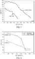
Figure 1 shows a hardness depth profile for carburized and carbo-nitrided Pyrowear® 675 tempered at 600 °F (2 times for 2 hours). -
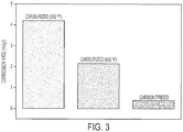
Figure 2 shows the hot hardness of carburized and carbo-nitrided Pyrowear® 675 up to 600 °F. -
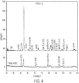
Figure 3 shows a corrosion rate comparison between carburized and carbo-nitrided Pyrowear® 675. -
Figure 4 shows XRD results for carburized and carbo-nitrided Pyrowear® 675. -
Figure 5 shows an approximate atom wt% of carbon and nitrogen as determined by Auger Electron Spectroscopy (AES). -
Figure 6 shows residual stress profiles of carburized and carbo-nitrided Pyrowear® 675. -
Figure 7 shows retained austenite profiles of carburized and carbo-nitrided Pyrowear® 675. -
Figure 8 is a schematic drawing of a rolling contact fatigue testing apparatus. -
Figure 9 shows a rolling contact fatigue life comparison between carburized and carbo-nitrided Pyrowear® 675. -
Figure 10 shows a SEM Micrograph of carbo-nitrided Pyrowear® 675. - Although the following description primarily concerns Pyrowear® 675 (hereinafter "P675") samples that were carbo-nitrided using different process parameters based on application requirements, the present teachings are also applicable to other martensitic stainless steels having similar elemental compositions, such as e.g., CSS-42L of Latrobe Specialty Steel Company, Latrobe, Pennsylvania, U.S.A.
- The initial carburizing cycle was conducted in a temperature range of 1625 °F - 1680 °F (885 °C - 916 °C) followed by a carbo-nitriding cycle in the temperature range of 1575 °F - 1625 °F (857 °C - 885 °C). The heat treat cycle time can be between 15-18 hours to produce a hard carburized case up to a depth of 900-1125 µm (38-45 mil). Saturation/diffusion cycles were alternately and repeatedly performed, in which acetylene was introduced into a vacuum chamber containing the steel and then a vacuum is drawn to about 0.1 atm (about 10 kPa). During the carbo-nitriding cycle, ammonia was simultaneously introduced together with the acetylene, followed again by the evacuation/diffusion phase. During the low pressure phases, carbon (and nitrogen, if present) contacting the surface of the metal diffuses into the surface (case) of the metal. The respective soaking temperatures were held constant during both phases.
- The carbo-nitrided stainless steel may then be quenched in liquid nitrogen (about - 196°C), followed by tempering twice at 600°F (315°C) for 2 hours. The resulting carbo-nitrided stainless steel had a Vickers hardness of about 840 HV (65.0 HRc).
- In the carbo-nitriding step, the ammonia-to-carbon differential ratio can preferably be in the range of 6-8:1. In such an embodiment, the hardened case of the article exhibits a presence of nitrogen up to a depth of 250 µm (10 mil). Approximately 0.5 wt% nitrogen was detected at the surface and 0.2 wt% nitrogen was detected to the depth of about 250 µm (10 mil). The process resulted in a carbon content in the hardened case in the range of 1.5 - 2 wt%. X-ray diffraction (XRD) results showed the formation of different metal nitrides (MxN & MN, where M represents metal) not present in carburized P675. The process formed FexN, CrxN, VxN, as will be discussed further below.
- The heat-treatment process according to the present teachings resulted in finely distributed carbides without carbide segregation at grain boundaries, as shown in
Figure 10 . A significant improvement in hardness profile, hot hardness and residual stress profiles were also observed, as will be discussed below. Furthermore, anodic polarization corrosion tests showed significant improvement in corrosion performance of carbo-nitrided (C-N) Pyrowear® 675. For example, the carbo-nitrided P675 exhibited at least 50% lower corrosion rate/yr as compared to a carburized P675 sample. - Further characterizing data is provided in the following, in which a P675 sample that was carbo-nitrided according to the above-mentioned process conditions (hereinafter "the carbo-nitrided P675 specimen") is compared to a P675 sample that was only carburized and the carbo-nitriding step was omitted (hereinafter "the carburized P675 specimen").
- The carburized and carbo-nitrided P675 specimens were cross sectioned and polished for hardness measurements. Micro-hardness at room temperature was measured as a function of depth (case to core). Three hardness measurements were taken at each depth and average hardness are reported. The hardness profiles for carbo-nitrided (C-N) samples are shown in
Figure 1 . A significant increase in hardness was observed with the carbo-nitrided P675 specimen in comparison with the carburized P675 specimen. While not wishing to be bound by theory, the substantial improvement in hardness of C-N material over the carburized P675 specimen is believed to be a significant factor in improving fatigue life and reducing wear rate, as will be demonstrated below. - Hot hardness measurements for the carburized and carbo-nitrided P675 specimens were performed at room temperature, 149°C (300°F), 204°C (400°F), 260°C (500°F) and 315°C (600°F). Five hardness measurements were taken at each temperature and average hardness are reported. Hardness was measured using Rockwell A scale and then converted to Rockwell C scale. The hardness of the carbo-nitrided P675 specimen is compared to the carburized P675 specimen in
Figure 2 . The carbo-nitrided P675 specimen exhibited a hot hardness profile superior to the carburized P675 specimen. While not wishing to be bound by theory, the substantial improvement in hot harness of carbo-nitrided material over carburized materials is believed to be a significant factor in improving fatigue life and allowing higher operating temperatures, as will be demonstrated below. - An anodic polarization test was used to quantify the corrosion resistance of the carburized and carbo-nitrided P675 specimens. The tests were conducted in 5% NaCl solution. When steel, particularly steel having a high Cr content, i.e. corrosion resistant steel, is exposed to a chloride-containing medium, it experiences a localized corrosion, i.e. corrosion pitting, rather than uniform corrosion. To determine the corrosion resistance of a material, the voltage at which the material begins to pit, i.e. the pitting potential (Epit), is determined from the polarization curve. The more positive (higher) the pitting potential, the more resistant the material is to pitting corrosion.
- The experimental test conditions and parameters were as follows. All samples were prepared by polishing to 600 grit (SiC paper), then rinsing with water, acetone, methanol, DI water and finally air drying. After drying, the samples were allowed to sit for at least 2 hours prior to testing.
- Anodic potentiodynamic scans were performed using a testing solution of simulated seawater (0.8 M NaCl). The open circuit potential (OCP) was monitored for 10 minutes prior to performing the scan to ensure stability of the corrosion potential. Polarization scan limits were performed from -0.1 (V) vs. OCP to +0.25 (V) vs. OCP. The scan rate was 0.5 mV/sec. The reference electrode used in all tests was saturated KCl.
- Bearing steel samples were tested by mounting each sample on the side of an electrochemical cell so that only the polished face was exposed to the testing solution. The working electrode (bearing steel sample) was mounted on the face of the corrosion cell and experiments were performed using a calomel reference electrode (SCE) and an expanded platinum mesh counter electrode. The electrical connection to the working electrode was made by spot welding pure nickel wire to the edge of the sample. The corrosion rate was calculated from a Tafel fit software.
- As shown in
Figure 3 , the carbo-nitrided P675 specimen exhibited a corrosion rate that was an order of magnitude lower than the two carburized P675 specimens (tempered respectively at 932 ° F and 600 ° F). - Corrosion is one of the main causes of bearing and gear failure. Use of highly corrosion resistant bearing material has the potential to significantly improve safety and reliability of advanced turbine engines. Improved bearing and gear material treated with the process according to the present teachings may also be advantageously utilized in a variety of high performance military and commercial aircraft turbine engines. Commercial and military ground vehicles also may benefit from the present teachings, as the present process is capable of improving corrosion resistance and thus system reliability and safety.
- The carburized and carbo-nitrided P675 specimens were analyzed by XRD technique to determine phases formed by each process. Introduction of nitrogen by the carbo-nitriding (C-N) process resulted in formation of additional metal nitrides (MN & MxN, wherein M represents metal) in the hard case as shown in
Figure 4 . While not wishing to be bound by theory, the formation of these metal nitrides is believed to be important to improving corrosion resistance. - Metal nitrides included in the case of the carbo-nitrided steel specimen include one or more of V2N, Cr2N, VN, Fe3N and Fe3N4.
- Auger electron spectroscopy (AES) was used to determine the weight percentages of nitrogen and carbon. The specimens were cross-sectioned and polished for AES analysis. After polishing, the specimens were removed from their mount and rinsed with acetone prior to analysis. The specimens were loaded into the AES vacuum system along with a polished 1074 steel sample and a sample of 99.9% iron foil, which were used as references. The AES vacuum system was baked overnight to achieve a base pressure in the 10-10 Torr range. This is necessary in order to attain a very low background carbon level. This work was done using a Varian model 981-2707 Auger spectrometer. The electron beam diameter for this work was ∼20 µm.
- Before initiating the profiles, the samples were argon ion-sputtered for several minutes in order to remove residual surface contaminants. The ion gun was left on during the profiles in order to avoid any re-contamination. A carbon level of 1.09 ± 0.04 wt% was measured on the 1074 steel sample, as compared with the expected composition range of 0.70 - 0.80 wt%. For the iron foil, the carbon level was measured to be < 0.2 wt%. Nitrogen in the range of 0.2 to 0.6 wt% was detected up to the depth of ∼ 250 µm (10 mil) as shown by AES nitrogen profile in
Figure 5 . - X-ray diffraction residual stress measurements were made at the surface and at nominal depths of 0.5, 1.0, 2.0, 3.0, 5.0, 7.0 and 10.0 x 10⁻³ in. (13, 25, 51, 76, 127, 178 and 254 x 10-3 mm). Measurements were made in the radial direction at the center of the flat face.
- X-ray diffraction residual stress measurements were performed using a two-angle sine-squared-psi technique, in accordance with SAE HS-784, employing the diffraction of chromium K-alpha radiation from the (211) planes of the BCC structure of the
Pyrowear® 675. The diffraction peak angular positions at each of the psi tilts employed for measurement were determined from the position of the K-alpha 1 diffraction peak separated from the superimposed K-alpha doublet assuming a Pearson VII function diffraction peak profile in the high back-reflection region. The diffracted intensity, peak breadth, and position of the K-alpha 1 diffraction peak were determined by fitting the Pearson VII function peak profile using a least squares regression after correction for the Lorentz polarization and absorption effects and for a linearly sloping background intensity. Material was removed electrolytically for subsurface measurements in order to minimize possible alteration of the subsurface residual stress distribution as a result of material removal. - All data obtained as a function of depth were corrected for the effects of the penetration of the radiation employed for residual stress measurement into the subsurface stress gradient. The stress gradient correction applied to the last depth measured is based upon an extrapolation to greater depths and may result in over correction at the last depth if the stress profile has been terminated in the presence of a steep gradient. Corrections for sectioning stress relaxation and for stress relaxation caused by layer removal are applied as appropriate.
- As was noted above, X-ray diffraction residual stress measurements were made at the surface and at nominal depths of 0.5, 1.0, 2.0, 3.0, 5.0, 7.0 and 10.0 x 10⁻³ in. (13, 25, 51, 76, 127, 178 and 254 x 10-3 mm). X-ray diffraction technique was used to measure residual stress and retained austenite as a function of depth. As shown in
Figure 6 , the carbo-nitriding process according to the present teachings produced higher compressive stresses, which are desirable to improve fatigue life. - The mean volume percent of retained austenite (RA) calculated from the four independently determined diffraction peak integrated intensity ratios and the standard deviation about the mean value are presented in
Fig. 7 . Uncertainties in austenite measurement that exceed one percent may be the result of preferred orientation present in a sample. In all x-ray diffraction quantitative analysis methods, the crystals in the sample are assumed to be randomly oriented so that the diffraction peak integrated intensities vary only with the relative volume fractions of the phases present. Standard deviations on the order of one volume percent are attainable on samples that have truly random orientation. However, because the relative intensities of the diffraction peaks for each phase depend upon the crystal structure and the preferred orientation (texture) present, the variation between the individual austenite results reported is not actually random experimental error. - Previous studies comparing the results obtained on orthogonal faces of highly textured steels have shown that the mean austenite content calculated is generally more reliable than indicated by the "standard deviation" reported. Carbide peaks near the austenite and martensite peaks may contribute to the integrated intensity and cause additional error and are avoided whenever possible. Performance of the technique is monitored using a secondary reference standard which is certified to contain 25.4% austenite with reference to NIST Standard Reference Material No. 487.
- A measurement on this sample during the investigation produced a value of 25.0 ± 0.5 percent. The RA profiles for the carburized and carbo-nitrided P675 specimens are shown in
Figure 7 . - Rolling contact fatigue (RCF) tests were conducted using a modified RCF tester. A schematic of the tester is shown in
Figure 8 . The "ball-on-rod" tester consists of a rotating cylindrical test specimen 1 (9.525 mm in diameter) stressed by rolling contact with three radially loaded balls 2 (12.7 mm in diameter) held spaced apart in aretainer 3. Theballs 2 are loaded against the rod 1 by two stationarytapered races 4 at a predetermined calibrated thrust load applied by three compression springs 5. To accelerate failure, high Hertzian stresses were used. The test configuration was set such that pure rolling conditions exist between the rod and balls. A constant rolling speed of 1.8 m/s (3600 rpm) was used for all experiments. - In the present configuration, the test head is heated using
band heaters 6. The test specimens 1 were continuously lubricated by dripping room temperature test lubricant onto the end of the specimen 1. An accelerometer, placed on the test head, was coupled with a shutdown device and monitored the vibrations of the assembly. When a preset vibration level was exceeded, thereby indicating the presence of fatigue spall or a surface crack, the motor, band heaters, and oil supply were automatically stopped. The test duration was recorded by an hour meter connected electronically to the motor. The test time required for a fatigue spall to develop on the rod was recorded, and the numbers of stress cycles were later calculated. Twenty tests were run on each test rod 1 at different axial positions for each lubricant/bearing material.New balls 2 were used for each test, and theraces 4 were replaced after 20 tests. - The
races 4 were made from VIM-VAR M50. Silicon nitride (Toshiba, TSN-03NH, Grade 5) rollingelements 2 were used to simulate a hybrid bearing configuration.Cages 3 were fabricated from AISI 4340. - A fully formulated polyolester base lubricant conforming to MIL-PRF-23699 (BP2197) specification was used as the lubricant with viscosity of 5 cSt @ 100°C. The calculated specific film thickness (λ) of values between 0.17-0.25 suggested that all tests were performed under boundary lubrication. The test specimens 1 were continuously lubricated at a constant flow rate of 22 ml/hr. The test lubricant was at room temperature prior to flowing into the test section.
- To accelerate fatigue failure, a maximum Hertzian stress of 5.5 GPa (800 ksi) was used. The test was performed at 350°F (177°C). A surface-initiated fatigue spall on the rod 1 was the test failing criterion. Tests were suspended after 300 hours of testing time, if no fatigue spall initiation occurred on the rod 1. The RCF results were analyzed using a two-parameter Weibull distribution with suspensions. Failures of the M50 race and the Si3Ni4 ball were treated as suspensions. Also, the tests with a run time in excess of 300 hours without a fatigue spall were also treated as suspensions in the Weibull analysis.
- As shown in
Figure 9 , the carbo-nitrided P675 specimen showed statistically significant improved fatigue life compared to the carburized P675 specimen (L10 life improved by 122% and L50 life improved by 146%). While not wishing to be bound by theory, significant improvement in fatigue life will result in improved reliability, longer component life and reduction in maintenance costs. - The microstructure of the carbo-nitrided P675 specimen is shown in
Figure 10 , in which fine, evenly-distributed carbides in the case can be seen. - An overall comparison of various steel treatment processes, as compared to carbo-nitriding according to the present teachings (bottommost entry) are shown below in Table 1. As can be seen, only the present carbo-nitriding technique was capable of providing both superior corrosion resistance and superior fatigue life performance.
Table 1 Specific Surface Treatment Corrosion resistance Fatigue Life Performance Carburized poor Accepted (used as base line) Cr ion implantation* poor Not tested TiN coating good poor TiN +Ag coating* poor poor low plastic burnishing* poor acceptable laser shock penning* poor not tested Carbo-nitrided superior superior *Post carburization treatment - Representative, non-limiting examples of the present invention were described above in detail. This detailed description is merely intended to teach a person of skill in the art further details for practicing preferred aspects of the present teachings and is not intended to limit the scope of the invention. Furthermore, each of the additional features and teachings disclosed above may be utilized separately or in conjunction with other features and teachings to provide improved stainless steel articles and methods for manufacturing the same.
Claims (13)
- A method comprising steps of:(a) providing an article comprised, at least in part, of a martensitic stainless steel, wherein the martensitic stainless steel consists of:0.02-0.50 wt% C, 0.1-1.5 wt% Mn, 0.10-2.0 wt% Si, 8.0-20.0 wt% Cr, 1.0-3.5 wt% Ni, 0.40-3.0 wt% Mo, 0.40-2.0 wt% V, 1.0-10.0 wt% Co, the balance being Fe; or0.03-0.10 wt% C, 0.5-1.0 wt% Mn, 0.20-0.6 wt% Si, 11.0-15.0 wt% Cr, 2.40-3.0 wt% Ni, 1.50-2.0 wt% Mo, 0.40-0.80 wt% V, 5.0-6.0 wt% Co, the balance being Fe, andwherein the martensitic stainless steel contains the following weight percentages of elements:

 (b) carburizing the article within a temperature range of 885 °C - 916 °C, and(c) then carbo-nitriding the article within a temperature range of 857 °C - 885 °C, wherein carbon and nitrogen are simultaneously introduced into the case of the stainless steel, thereby producing a case-hardened martensitic stainless steel article.
 - The method according to claim 1, wherein a nitrogen:carbon differential ratio in step (c) is between 6-8:1.
- The method according to claim 2, wherein in step (c) nitrogen is provided by ammonia and carbon is provided by acetylene and/or propane.
- The method according to any preceding claim, wherein the total time for steps (b) and (c) is between 15-18 hours.
- The method according to any preceding claim, wherein the case-hardened martensitic stainless steel article contains carbon in the range of 1.5 - 2 wt% in the hardened case at least up to a depth of 500 µm.
- The method according to any preceding claim, wherein the case-hardened martensitic stainless steel article is subsequently:(d) quenched in liquid nitrogen and(e) then tempered twice at 301°C - 329 °C for 2 hours.
- The method according to any preceding claim, wherein the case-hardened martensitic stainless steel article has a hardness of at least 800 Hv (∼ 63.7 HRc) at a depth between 0.25 to 1.0 mm.
- The method according to any preceding claim, wherein the case-hardened martensitic stainless steel article contains at least 0.5 wt% nitrogen in at least one portion of the hardened case and at least 0.2 wt% nitrogen at a depth of 200 µm.
- The method according to any preceding claim, wherein the case-hardened martensitic stainless steel article exhibits a residual stress of at least 500 MPa in the hardened case.
- The method according to any preceding claim, wherein at least one portion of the hardened case of the case-hardened martensitic stainless steel article comprises at least 16 volume percent of retained austenite.
- The method according to any preceding claim, wherein the article is a bearing ring.
- A bearing ring comprised of a carbo-nitrided martensitic stainless steel having:a hard carburized case up to a depth of 900-1125 µm,a presence of nitrogen or nitrides up to depth of 250 µm,0.3-0.7 wt% nitrogen at the surface and 0.1-0.3 wt% nitrogen at a depth of 250 µm, andcarbon in the range of 1.5 - 2 wt% in the hardened case,wherein the bearing ring has a core consisting of:0.02-0.50 wt% C, 0.1-1.5 wt% Mn, 0.10-2.0 wt% Si, 8.0-20.0 wt% Cr, 1.0-3.5 wt% Ni, 0.40-3.0 wt% Mo, 0.40-2.0 wt% V, 1.0-10.0 wt% Co, the balance being Fe; or0.03-0.10 wt% C, 0.5-1.0 wt% Mn, 0.20-0.6 wt% Si, 11.0-15.0 wt% Cr, 2.40-3.0 wt% Ni, 1.50-2.0 wt% Mo, 0.40-0.80 wt% V, 5.0-6.0 wt% Co, the balance being Fe,wherein the core of the bearing ring contains the following weight percentages of elements:


- The bearing ring according to claim 12, wherein the hardened case of the bearing ring has:a hardness of between 800-850 Hv (∼63.7 to 65.4 HRc) at a depth between 0.25 to 1.0 mm,a hardness of at least 63 HRc (∼772 HV) at 149°C,a hardness of at least 62 HRc (∼ 745 HV) at 204°C anda residual stress of at least 500 MPa; andwherein at least one portion of the hardened case of the bearing ring comprises at least 16 volume percent of retained austenite.
Applications Claiming Priority (2)
| Application Number | Priority Date | Filing Date | Title |
|---|---|---|---|
| US201161492675P | 2011-06-02 | 2011-06-02 | |
| PCT/US2012/040095 WO2012166851A1 (en) | 2011-06-02 | 2012-05-31 | Carbo-nitriding process for martensitic stainless steel and stainless steel article having improved corrosion resistance |
Publications (3)
| Publication Number | Publication Date |
|---|---|
| EP2739761A1 EP2739761A1 (en) | 2014-06-11 |
| EP2739761A4 EP2739761A4 (en) | 2015-08-19 |
| EP2739761B1 true EP2739761B1 (en) | 2017-05-24 |
Family
ID=47259834
Family Applications (1)
| Application Number | Title | Priority Date | Filing Date |
|---|---|---|---|
| EP12792569.1A Active EP2739761B1 (en) | 2011-06-02 | 2012-05-31 | Carbo-nitriding process for martensitic stainless steel and stainless steel article having improved corrosion resistance |
Country Status (3)
| Country | Link |
|---|---|
| US (2) | US10053763B2 (en) |
| EP (1) | EP2739761B1 (en) |
| WO (1) | WO2012166851A1 (en) |
Cited By (1)
| Publication number | Priority date | Publication date | Assignee | Title |
|---|---|---|---|---|
| US11905602B2 (en) | 2022-02-11 | 2024-02-20 | SKF Aerospace France S.A.S | Method for reinforcing a steel component by carbonitriding |
Families Citing this family (8)
| Publication number | Priority date | Publication date | Assignee | Title |
|---|---|---|---|---|
| DE102012212426B3 (en) * | 2012-07-16 | 2013-08-29 | Schaeffler Technologies AG & Co. KG | Rolling element, in particular rolling bearing ring |
| EP2971210B1 (en) * | 2013-03-15 | 2018-12-19 | United Technologies Corporation | Component configured from martensitic stainless steel |
| EP2975146A1 (en) * | 2014-07-16 | 2016-01-20 | Uddeholms AB | Cold work tool steel |
| DE102016215812A1 (en) * | 2016-08-23 | 2018-03-01 | Schaeffler Technologies AG & Co. KG | Process for processing a case hardening steel to form a component |
| CN112628283A (en) * | 2020-12-29 | 2021-04-09 | 中国航发哈尔滨轴承有限公司 | High-temperature corrosion-resistant rod end joint bearing |
| CN114962460A (en) | 2021-02-25 | 2022-08-30 | 斯凯孚公司 | Heat Treated Roller Bearing Rings |
| WO2023114498A1 (en) | 2021-12-17 | 2023-06-22 | Carpenter Technology Corporation | Articles fabricated from cold-worked and case-hardened essentially co-free stainless steel alloys and methods of fabrication thereof |
| JP7599460B2 (en) * | 2022-10-04 | 2024-12-13 | Ntn株式会社 | Machine parts, rolling bearings and ball screws |
Family Cites Families (42)
| Publication number | Priority date | Publication date | Assignee | Title |
|---|---|---|---|---|
| GB1185640A (en) | 1966-12-21 | 1970-03-25 | Ici Ltd | Process for Casehardening Steels |
| JPS5277836A (en) | 1975-12-23 | 1977-06-30 | Fujikoshi Kk | Surface treatment of martensitic stainless steel |
| US4191599A (en) | 1978-09-13 | 1980-03-04 | Ford Motor Company | Method of heat treating high carbon alloy steel parts to develop surface compressive residual stresses |
| DE3718240C1 (en) | 1987-05-30 | 1988-01-14 | Ewald Schwing | Process for the heat treatment of metallic workpieces in a gas-flowed fluidized bed |
| JPH0756043B2 (en) | 1988-09-27 | 1995-06-14 | マツダ株式会社 | Steel member manufacturing method |
| US5002729A (en) | 1989-08-04 | 1991-03-26 | Carpenter Technology Corporation | Case hardenable corrosion resistant steel alloy and article made therefrom |
| JPH05148535A (en) | 1991-06-07 | 1993-06-15 | Kobe Steel Ltd | Production of surface hardened parts having decreased heat treating strain and excellent bending fatigue strength |
| US5424028A (en) | 1993-12-23 | 1995-06-13 | Latrobe Steel Company | Case carburized stainless steel alloy for high temperature applications |
| JP3308377B2 (en) | 1994-03-09 | 2002-07-29 | 大同特殊鋼株式会社 | Gear with excellent tooth surface strength and method of manufacturing the same |
| JP3750202B2 (en) | 1996-02-21 | 2006-03-01 | 日本精工株式会社 | Rolling bearing |
| GB9614303D0 (en) | 1996-07-08 | 1996-09-04 | Nsk Rhp Europe Technology Co Ltd | Surface treatment of bearing steels |
| JP3909902B2 (en) | 1996-12-17 | 2007-04-25 | 株式会社小松製作所 | Steel parts for high surface pressure resistance and method for producing the same |
| JP3311949B2 (en) | 1996-12-18 | 2002-08-05 | 有限会社金属技術研究所 | Surface hardened chain |
| JP3894635B2 (en) | 1997-08-11 | 2007-03-22 | 株式会社小松製作所 | Carburized member, manufacturing method thereof, and carburizing system |
| GB2328953B (en) | 1997-09-08 | 2002-07-03 | Nsk Rhp Europe Technology Co Ltd | Improved steel hardening process |
| US6248186B1 (en) | 1997-11-07 | 2001-06-19 | Nsk Ltd. | Ball-and-roller bearing and method of manufacturing the same |
| JP4100751B2 (en) | 1998-01-30 | 2008-06-11 | 株式会社小松製作所 | Rolling member and manufacturing method thereof |
| WO2001068933A2 (en) * | 2000-03-14 | 2001-09-20 | The Timken Company | High performance carburizing stainless steel for high temperature use |
| JP2001336538A (en) | 2000-05-26 | 2001-12-07 | Nsk Ltd | Rolling bearing and its manufacturing method |
| JP4442030B2 (en) | 2000-05-31 | 2010-03-31 | 日本精工株式会社 | Method for manufacturing rolling support device |
| JP4724275B2 (en) | 2000-07-17 | 2011-07-13 | 株式会社リケン | Piston ring excellent in scuffing resistance, cracking resistance and fatigue resistance, and manufacturing method thereof |
| JP2002188702A (en) | 2000-12-25 | 2002-07-05 | Nissan Motor Co Ltd | Rolling element for continuously variable transmission and method of manufacturing the same |
| DE60141304D1 (en) * | 2001-12-13 | 2010-03-25 | Koyo Thermo Sys Co Ltd | VACUUM CARBONI TRIER PROCEDURE |
| JP3961390B2 (en) | 2002-10-04 | 2007-08-22 | エア・ウォーター株式会社 | Surface carbonitrided stainless steel parts with excellent wear resistance and manufacturing method thereof |
| DE10251413B3 (en) * | 2002-11-01 | 2004-03-25 | Sandvik Ab | Use of a dispersion hardened martensitic non-rusting chromium-nickel steel in the manufacture of machine-driven rotating tools, preferably drilling, milling, grinding and cutting tools |
| JP4390576B2 (en) | 2003-03-04 | 2009-12-24 | 株式会社小松製作所 | Rolling member |
| JP4390526B2 (en) | 2003-03-11 | 2009-12-24 | 株式会社小松製作所 | Rolling member and manufacturing method thereof |
| US7384488B2 (en) | 2003-09-18 | 2008-06-10 | Mahindra & Mahindra Ltd | Method for producing gears and/or shaft components with superior bending fatigue strength and pitting fatigue life from conventional alloy steels |
| US7208052B2 (en) | 2003-12-23 | 2007-04-24 | Rolls-Royce Corporation | Method for carburizing steel components |
| US7186304B2 (en) | 2004-06-02 | 2007-03-06 | United Technologies Corporation | Carbo-nitrided case hardened martensitic stainless steels |
| US8070364B2 (en) | 2004-08-04 | 2011-12-06 | Schaeffler Kg | Rolling bearing of ceramic and steel engaging parts |
| DE102004041964B4 (en) | 2004-08-04 | 2012-04-26 | Schaeffler Technologies Gmbh & Co. Kg | Machine element for rolling load |
| FR2884523B1 (en) | 2005-04-19 | 2008-01-11 | Const Mecaniques Sa Et | LOW PRESSURE CARBONITRUTING PROCESS AND FURNACE |
| DE102006025008B4 (en) | 2006-05-30 | 2022-09-15 | Schaeffler Technologies AG & Co. KG | Process for hardening running surfaces of roller bearing components |
| US7910217B2 (en) | 2006-11-07 | 2011-03-22 | Ues, Inc. | Wear resistant coatings for race land regions of bearing materials |
| JP2008163430A (en) | 2006-12-28 | 2008-07-17 | Jtekt Corp | High corrosion resistance member and method for manufacturing the same |
| CN101338358B (en) | 2007-07-05 | 2010-06-02 | 刘正贤 | Method for improving surface hardness of martensitic stainless steel |
| US7972449B2 (en) | 2008-01-03 | 2011-07-05 | GM Global Technology Operations LLC | Corrosion resistant metal composite for electrochemical devices and methods of producing the same |
| JP5489111B2 (en) * | 2009-03-25 | 2014-05-14 | Ntn株式会社 | Bearing parts, rolling bearings and bearing parts manufacturing method |
| US8425691B2 (en) | 2010-07-21 | 2013-04-23 | Kenneth H. Moyer | Stainless steel carburization process |
| US8308873B2 (en) | 2011-04-11 | 2012-11-13 | United Technologies Corporation | Method of processing steel and steel article |
| EP3696286A1 (en) | 2013-11-25 | 2020-08-19 | United Technologies Corporation | A method for forming a martensitic stainless steel material and a case hardened component |
-
2012
- 2012-05-31 WO PCT/US2012/040095 patent/WO2012166851A1/en not_active Ceased
- 2012-05-31 US US14/131,225 patent/US10053763B2/en active Active
- 2012-05-31 EP EP12792569.1A patent/EP2739761B1/en active Active
-
2018
- 2018-07-19 US US16/039,564 patent/US11667999B2/en active Active
Cited By (1)
| Publication number | Priority date | Publication date | Assignee | Title |
|---|---|---|---|---|
| US11905602B2 (en) | 2022-02-11 | 2024-02-20 | SKF Aerospace France S.A.S | Method for reinforcing a steel component by carbonitriding |
Also Published As
| Publication number | Publication date |
|---|---|
| EP2739761A4 (en) | 2015-08-19 |
| EP2739761A1 (en) | 2014-06-11 |
| US20180320262A1 (en) | 2018-11-08 |
| WO2012166851A1 (en) | 2012-12-06 |
| US20140305548A1 (en) | 2014-10-16 |
| US11667999B2 (en) | 2023-06-06 |
| US10053763B2 (en) | 2018-08-21 |
Similar Documents
| Publication | Publication Date | Title |
|---|---|---|
| US11667999B2 (en) | Carbo-nitriding process for martensitic stainless steel and stainless steel article having improved corrosion resistance | |
| Ooi et al. | Duplex hardening of steels for aeroengine bearings | |
| EP0013063B1 (en) | Method of treating the surfaces of high carbon steel bodies | |
| Cao et al. | Insights into room-and elevated-temperature micro-mechanisms of laser shock peened M50 steel with superior tribological performance | |
| Kanchanomai et al. | Effect of residual stress on fatigue failure of carbonitrided low-carbon steel | |
| Genel et al. | Corrosion fatigue behaviour of ion nitrided AISI 4140 steel | |
| Lee et al. | Grain refinement in bearing steels using a double-quenching heat-treatment process | |
| Clark et al. | Comparison of austempering and quench-and-tempering processes for carburized automotive steels | |
| JPWO1999010557A1 (en) | Rolling bearing manufacturing method | |
| Trausmuth et al. | Damage models of different hardness layers subjected to point contact | |
| Senatorski et al. | Tribology of Nitrided and Nitrocarburized steels | |
| Li et al. | Microstructure and mechanical properties of Fe-Cr-2Ni-Mo-V steel in carburizing process | |
| Zhu et al. | Bending fatigue behavior of metastable and stable austenitic stainless steels with different surface morphologies | |
| Chen et al. | Effect of grinding depth on fatigue fracture behaviors of 40Cr steel | |
| JP5592541B1 (en) | Bearing parts and rolling bearings | |
| Chen et al. | Rolling Contact Fatigue Behaviors of 20CrNi2Mo Steel by a New Carbon and Nitrogen Composite Infiltration Process | |
| Mason et al. | Optimizing Carburization in 8620H Steel Components | |
| Citti et al. | Mechanical characterization of a new low carbon bainitic steel for high performance crankshaft | |
| Nasser et al. | Experimental study on notch shape and liquid carbonitriding specimens under bending loading | |
| EP3110979A1 (en) | Process for treating steel components | |
| Sun et al. | Enhancing the High‐Temperature Rolling Contact Fatigue Performance of Carburizing 8620H Steel Through Ultrasonic Surface Rolling Process | |
| Sanders | Effects of shot peening on the bending fatigue behavior of a carburized SAE 4320 steel, The | |
| Lipshaw et al. | A Review of Austempering for Bearing Applications | |
| JP6211814B2 (en) | Bearing parts and rolling bearings | |
| Steinbacher et al. | Heat Treatment of 20MnCr5 and X20NiCrAlMoV6-5-2-1 for High Temperature Gear Applications |
Legal Events
| Date | Code | Title | Description |
|---|---|---|---|
| PUAI | Public reference made under article 153(3) epc to a published international application that has entered the european phase |
Free format text: ORIGINAL CODE: 0009012 |
|
| 17P | Request for examination filed |
Effective date: 20140331 |
|
| AK | Designated contracting states |
Kind code of ref document: A1 Designated state(s): AL AT BE BG CH CY CZ DE DK EE ES FI FR GB GR HR HU IE IS IT LI LT LU LV MC MK MT NL NO PL PT RO RS SE SI SK SM TR |
|
| DAX | Request for extension of the european patent (deleted) | ||
| RA4 | Supplementary search report drawn up and despatched (corrected) |
Effective date: 20150716 |
|
| RIC1 | Information provided on ipc code assigned before grant |
Ipc: C23C 8/00 20060101AFI20150710BHEP |
|
| GRAP | Despatch of communication of intention to grant a patent |
Free format text: ORIGINAL CODE: EPIDOSNIGR1 |
|
| INTG | Intention to grant announced |
Effective date: 20161221 |
|
| GRAS | Grant fee paid |
Free format text: ORIGINAL CODE: EPIDOSNIGR3 |
|
| GRAA | (expected) grant |
Free format text: ORIGINAL CODE: 0009210 |
|
| AK | Designated contracting states |
Kind code of ref document: B1 Designated state(s): AL AT BE BG CH CY CZ DE DK EE ES FI FR GB GR HR HU IE IS IT LI LT LU LV MC MK MT NL NO PL PT RO RS SE SI SK SM TR |
|
| REG | Reference to a national code |
Ref country code: GB Ref legal event code: FG4D |
|
| REG | Reference to a national code |
Ref country code: CH Ref legal event code: EP |
|
| REG | Reference to a national code |
Ref country code: IE Ref legal event code: FG4D |
|
| REG | Reference to a national code |
Ref country code: AT Ref legal event code: REF Ref document number: 896068 Country of ref document: AT Kind code of ref document: T Effective date: 20170615 |
|
| REG | Reference to a national code |
Ref country code: FR Ref legal event code: PLFP Year of fee payment: 6 |
|
| REG | Reference to a national code |
Ref country code: DE Ref legal event code: R096 Ref document number: 602012032822 Country of ref document: DE |
|
| REG | Reference to a national code |
Ref country code: NL Ref legal event code: MP Effective date: 20170524 |
|
| REG | Reference to a national code |
Ref country code: LT Ref legal event code: MG4D |
|
| REG | Reference to a national code |
Ref country code: AT Ref legal event code: MK05 Ref document number: 896068 Country of ref document: AT Kind code of ref document: T Effective date: 20170524 |
|
| PG25 | Lapsed in a contracting state [announced via postgrant information from national office to epo] |
Ref country code: NO Free format text: LAPSE BECAUSE OF FAILURE TO SUBMIT A TRANSLATION OF THE DESCRIPTION OR TO PAY THE FEE WITHIN THE PRESCRIBED TIME-LIMIT Effective date: 20170824 Ref country code: ES Free format text: LAPSE BECAUSE OF FAILURE TO SUBMIT A TRANSLATION OF THE DESCRIPTION OR TO PAY THE FEE WITHIN THE PRESCRIBED TIME-LIMIT Effective date: 20170524 Ref country code: LT Free format text: LAPSE BECAUSE OF FAILURE TO SUBMIT A TRANSLATION OF THE DESCRIPTION OR TO PAY THE FEE WITHIN THE PRESCRIBED TIME-LIMIT Effective date: 20170524 Ref country code: HR Free format text: LAPSE BECAUSE OF FAILURE TO SUBMIT A TRANSLATION OF THE DESCRIPTION OR TO PAY THE FEE WITHIN THE PRESCRIBED TIME-LIMIT Effective date: 20170524 Ref country code: AT Free format text: LAPSE BECAUSE OF FAILURE TO SUBMIT A TRANSLATION OF THE DESCRIPTION OR TO PAY THE FEE WITHIN THE PRESCRIBED TIME-LIMIT Effective date: 20170524 Ref country code: FI Free format text: LAPSE BECAUSE OF FAILURE TO SUBMIT A TRANSLATION OF THE DESCRIPTION OR TO PAY THE FEE WITHIN THE PRESCRIBED TIME-LIMIT Effective date: 20170524 Ref country code: GR Free format text: LAPSE BECAUSE OF FAILURE TO SUBMIT A TRANSLATION OF THE DESCRIPTION OR TO PAY THE FEE WITHIN THE PRESCRIBED TIME-LIMIT Effective date: 20170825 |
|
| PG25 | Lapsed in a contracting state [announced via postgrant information from national office to epo] |
Ref country code: SE Free format text: LAPSE BECAUSE OF FAILURE TO SUBMIT A TRANSLATION OF THE DESCRIPTION OR TO PAY THE FEE WITHIN THE PRESCRIBED TIME-LIMIT Effective date: 20170524 Ref country code: BG Free format text: LAPSE BECAUSE OF FAILURE TO SUBMIT A TRANSLATION OF THE DESCRIPTION OR TO PAY THE FEE WITHIN THE PRESCRIBED TIME-LIMIT Effective date: 20170824 Ref country code: NL Free format text: LAPSE BECAUSE OF FAILURE TO SUBMIT A TRANSLATION OF THE DESCRIPTION OR TO PAY THE FEE WITHIN THE PRESCRIBED TIME-LIMIT Effective date: 20170524 Ref country code: RS Free format text: LAPSE BECAUSE OF FAILURE TO SUBMIT A TRANSLATION OF THE DESCRIPTION OR TO PAY THE FEE WITHIN THE PRESCRIBED TIME-LIMIT Effective date: 20170524 Ref country code: LV Free format text: LAPSE BECAUSE OF FAILURE TO SUBMIT A TRANSLATION OF THE DESCRIPTION OR TO PAY THE FEE WITHIN THE PRESCRIBED TIME-LIMIT Effective date: 20170524 Ref country code: IS Free format text: LAPSE BECAUSE OF FAILURE TO SUBMIT A TRANSLATION OF THE DESCRIPTION OR TO PAY THE FEE WITHIN THE PRESCRIBED TIME-LIMIT Effective date: 20170924 |
|
| REG | Reference to a national code |
Ref country code: CH Ref legal event code: PL |
|
| PG25 | Lapsed in a contracting state [announced via postgrant information from national office to epo] |
Ref country code: SK Free format text: LAPSE BECAUSE OF FAILURE TO SUBMIT A TRANSLATION OF THE DESCRIPTION OR TO PAY THE FEE WITHIN THE PRESCRIBED TIME-LIMIT Effective date: 20170524 Ref country code: CZ Free format text: LAPSE BECAUSE OF FAILURE TO SUBMIT A TRANSLATION OF THE DESCRIPTION OR TO PAY THE FEE WITHIN THE PRESCRIBED TIME-LIMIT Effective date: 20170524 Ref country code: RO Free format text: LAPSE BECAUSE OF FAILURE TO SUBMIT A TRANSLATION OF THE DESCRIPTION OR TO PAY THE FEE WITHIN THE PRESCRIBED TIME-LIMIT Effective date: 20170524 Ref country code: EE Free format text: LAPSE BECAUSE OF FAILURE TO SUBMIT A TRANSLATION OF THE DESCRIPTION OR TO PAY THE FEE WITHIN THE PRESCRIBED TIME-LIMIT Effective date: 20170524 Ref country code: DK Free format text: LAPSE BECAUSE OF FAILURE TO SUBMIT A TRANSLATION OF THE DESCRIPTION OR TO PAY THE FEE WITHIN THE PRESCRIBED TIME-LIMIT Effective date: 20170524 |
|
| REG | Reference to a national code |
Ref country code: IE Ref legal event code: MM4A |
|
| REG | Reference to a national code |
Ref country code: DE Ref legal event code: R097 Ref document number: 602012032822 Country of ref document: DE |
|
| PG25 | Lapsed in a contracting state [announced via postgrant information from national office to epo] |
Ref country code: SM Free format text: LAPSE BECAUSE OF FAILURE TO SUBMIT A TRANSLATION OF THE DESCRIPTION OR TO PAY THE FEE WITHIN THE PRESCRIBED TIME-LIMIT Effective date: 20170524 Ref country code: CH Free format text: LAPSE BECAUSE OF NON-PAYMENT OF DUE FEES Effective date: 20170531 Ref country code: IT Free format text: LAPSE BECAUSE OF FAILURE TO SUBMIT A TRANSLATION OF THE DESCRIPTION OR TO PAY THE FEE WITHIN THE PRESCRIBED TIME-LIMIT Effective date: 20170524 Ref country code: LI Free format text: LAPSE BECAUSE OF NON-PAYMENT OF DUE FEES Effective date: 20170531 Ref country code: PL Free format text: LAPSE BECAUSE OF FAILURE TO SUBMIT A TRANSLATION OF THE DESCRIPTION OR TO PAY THE FEE WITHIN THE PRESCRIBED TIME-LIMIT Effective date: 20170524 |
|
| PG25 | Lapsed in a contracting state [announced via postgrant information from national office to epo] |
Ref country code: LU Free format text: LAPSE BECAUSE OF NON-PAYMENT OF DUE FEES Effective date: 20170531 |
|
| PLBE | No opposition filed within time limit |
Free format text: ORIGINAL CODE: 0009261 |
|
| STAA | Information on the status of an ep patent application or granted ep patent |
Free format text: STATUS: NO OPPOSITION FILED WITHIN TIME LIMIT |
|
| GBPC | Gb: european patent ceased through non-payment of renewal fee |
Effective date: 20170824 |
|
| REG | Reference to a national code |
Ref country code: BE Ref legal event code: MM Effective date: 20170531 |
|
| PG25 | Lapsed in a contracting state [announced via postgrant information from national office to epo] |
Ref country code: IE Free format text: LAPSE BECAUSE OF NON-PAYMENT OF DUE FEES Effective date: 20170531 |
|
| 26N | No opposition filed |
Effective date: 20180227 |
|
| REG | Reference to a national code |
Ref country code: FR Ref legal event code: PLFP Year of fee payment: 7 |
|
| PG25 | Lapsed in a contracting state [announced via postgrant information from national office to epo] |
Ref country code: SI Free format text: LAPSE BECAUSE OF FAILURE TO SUBMIT A TRANSLATION OF THE DESCRIPTION OR TO PAY THE FEE WITHIN THE PRESCRIBED TIME-LIMIT Effective date: 20170524 |
|
| PG25 | Lapsed in a contracting state [announced via postgrant information from national office to epo] |
Ref country code: GB Free format text: LAPSE BECAUSE OF NON-PAYMENT OF DUE FEES Effective date: 20170824 |
|
| PG25 | Lapsed in a contracting state [announced via postgrant information from national office to epo] |
Ref country code: BE Free format text: LAPSE BECAUSE OF NON-PAYMENT OF DUE FEES Effective date: 20170531 |
|
| PG25 | Lapsed in a contracting state [announced via postgrant information from national office to epo] |
Ref country code: MT Free format text: LAPSE BECAUSE OF NON-PAYMENT OF DUE FEES Effective date: 20170531 |
|
| REG | Reference to a national code |
Ref country code: GB Ref legal event code: S28 Free format text: APPLICATION FILED |
|
| REG | Reference to a national code |
Ref country code: GB Ref legal event code: S28 Free format text: RESTORATION ALLOWED Effective date: 20190110 |
|
| PG25 | Lapsed in a contracting state [announced via postgrant information from national office to epo] |
Ref country code: MC Free format text: LAPSE BECAUSE OF FAILURE TO SUBMIT A TRANSLATION OF THE DESCRIPTION OR TO PAY THE FEE WITHIN THE PRESCRIBED TIME-LIMIT Effective date: 20170524 Ref country code: HU Free format text: LAPSE BECAUSE OF FAILURE TO SUBMIT A TRANSLATION OF THE DESCRIPTION OR TO PAY THE FEE WITHIN THE PRESCRIBED TIME-LIMIT; INVALID AB INITIO Effective date: 20120531 |
|
| PG25 | Lapsed in a contracting state [announced via postgrant information from national office to epo] |
Ref country code: CY Free format text: LAPSE BECAUSE OF NON-PAYMENT OF DUE FEES Effective date: 20170524 |
|
| PG25 | Lapsed in a contracting state [announced via postgrant information from national office to epo] |
Ref country code: MK Free format text: LAPSE BECAUSE OF FAILURE TO SUBMIT A TRANSLATION OF THE DESCRIPTION OR TO PAY THE FEE WITHIN THE PRESCRIBED TIME-LIMIT Effective date: 20170524 |
|
| PG25 | Lapsed in a contracting state [announced via postgrant information from national office to epo] |
Ref country code: TR Free format text: LAPSE BECAUSE OF FAILURE TO SUBMIT A TRANSLATION OF THE DESCRIPTION OR TO PAY THE FEE WITHIN THE PRESCRIBED TIME-LIMIT Effective date: 20170524 |
|
| PG25 | Lapsed in a contracting state [announced via postgrant information from national office to epo] |
Ref country code: PT Free format text: LAPSE BECAUSE OF FAILURE TO SUBMIT A TRANSLATION OF THE DESCRIPTION OR TO PAY THE FEE WITHIN THE PRESCRIBED TIME-LIMIT Effective date: 20170524 |
|
| PG25 | Lapsed in a contracting state [announced via postgrant information from national office to epo] |
Ref country code: AL Free format text: LAPSE BECAUSE OF FAILURE TO SUBMIT A TRANSLATION OF THE DESCRIPTION OR TO PAY THE FEE WITHIN THE PRESCRIBED TIME-LIMIT Effective date: 20170524 |
|
| PGFP | Annual fee paid to national office [announced via postgrant information from national office to epo] |
Ref country code: DE Payment date: 20250529 Year of fee payment: 14 |
|
| PGFP | Annual fee paid to national office [announced via postgrant information from national office to epo] |
Ref country code: GB Payment date: 20250520 Year of fee payment: 14 |
|
| PGFP | Annual fee paid to national office [announced via postgrant information from national office to epo] |
Ref country code: FR Payment date: 20250526 Year of fee payment: 14 |
|
| P01 | Opt-out of the competence of the unified patent court (upc) registered |
Free format text: CASE NUMBER: UPC_APP_0011656_2739761/2025 Effective date: 20251030 |