EP2738951A2 - Interference management in wireless multi-access communication networks - Google Patents
Interference management in wireless multi-access communication networks Download PDFInfo
- Publication number
- EP2738951A2 EP2738951A2 EP13005589.0A EP13005589A EP2738951A2 EP 2738951 A2 EP2738951 A2 EP 2738951A2 EP 13005589 A EP13005589 A EP 13005589A EP 2738951 A2 EP2738951 A2 EP 2738951A2
- Authority
- EP
- European Patent Office
- Prior art keywords
- interference
- corresponds
- cell
- cells
- opt
- Prior art date
- Legal status (The legal status is an assumption and is not a legal conclusion. Google has not performed a legal analysis and makes no representation as to the accuracy of the status listed.)
- Granted
Links
Images



Classifications
-
- H—ELECTRICITY
- H04—ELECTRIC COMMUNICATION TECHNIQUE
- H04L—TRANSMISSION OF DIGITAL INFORMATION, e.g. TELEGRAPHIC COMMUNICATION
- H04L5/00—Arrangements affording multiple use of the transmission path
- H04L5/003—Arrangements for allocating sub-channels of the transmission path
- H04L5/0058—Allocation criteria
- H04L5/0073—Allocation arrangements that take into account other cell interferences
-
- H—ELECTRICITY
- H04—ELECTRIC COMMUNICATION TECHNIQUE
- H04B—TRANSMISSION
- H04B7/00—Radio transmission systems, i.e. using radiation field
- H04B7/02—Diversity systems; Multi-antenna system, i.e. transmission or reception using multiple antennas
- H04B7/022—Site diversity; Macro-diversity
- H04B7/024—Co-operative use of antennas of several sites, e.g. in co-ordinated multipoint or co-operative multiple-input multiple-output [MIMO] systems
-
- H—ELECTRICITY
- H04—ELECTRIC COMMUNICATION TECHNIQUE
- H04B—TRANSMISSION
- H04B7/00—Radio transmission systems, i.e. using radiation field
- H04B7/02—Diversity systems; Multi-antenna system, i.e. transmission or reception using multiple antennas
- H04B7/04—Diversity systems; Multi-antenna system, i.e. transmission or reception using multiple antennas using two or more spaced independent antennas
- H04B7/0413—MIMO systems
- H04B7/0456—Selection of precoding matrices or codebooks, e.g. using matrices antenna weighting
-
- H—ELECTRICITY
- H04—ELECTRIC COMMUNICATION TECHNIQUE
- H04B—TRANSMISSION
- H04B7/00—Radio transmission systems, i.e. using radiation field
- H04B7/02—Diversity systems; Multi-antenna system, i.e. transmission or reception using multiple antennas
- H04B7/04—Diversity systems; Multi-antenna system, i.e. transmission or reception using multiple antennas using two or more spaced independent antennas
- H04B7/06—Diversity systems; Multi-antenna system, i.e. transmission or reception using multiple antennas using two or more spaced independent antennas at the transmitting station
- H04B7/0613—Diversity systems; Multi-antenna system, i.e. transmission or reception using multiple antennas using two or more spaced independent antennas at the transmitting station using simultaneous transmission
- H04B7/0615—Diversity systems; Multi-antenna system, i.e. transmission or reception using multiple antennas using two or more spaced independent antennas at the transmitting station using simultaneous transmission of weighted versions of same signal
- H04B7/0619—Diversity systems; Multi-antenna system, i.e. transmission or reception using multiple antennas using two or more spaced independent antennas at the transmitting station using simultaneous transmission of weighted versions of same signal using feedback from receiving side
- H04B7/0621—Feedback content
- H04B7/0634—Antenna weights or vector/matrix coefficients
-
- H—ELECTRICITY
- H04—ELECTRIC COMMUNICATION TECHNIQUE
- H04B—TRANSMISSION
- H04B7/00—Radio transmission systems, i.e. using radiation field
- H04B7/02—Diversity systems; Multi-antenna system, i.e. transmission or reception using multiple antennas
- H04B7/04—Diversity systems; Multi-antenna system, i.e. transmission or reception using multiple antennas using two or more spaced independent antennas
- H04B7/06—Diversity systems; Multi-antenna system, i.e. transmission or reception using multiple antennas using two or more spaced independent antennas at the transmitting station
- H04B7/0613—Diversity systems; Multi-antenna system, i.e. transmission or reception using multiple antennas using two or more spaced independent antennas at the transmitting station using simultaneous transmission
- H04B7/0615—Diversity systems; Multi-antenna system, i.e. transmission or reception using multiple antennas using two or more spaced independent antennas at the transmitting station using simultaneous transmission of weighted versions of same signal
- H04B7/0619—Diversity systems; Multi-antenna system, i.e. transmission or reception using multiple antennas using two or more spaced independent antennas at the transmitting station using simultaneous transmission of weighted versions of same signal using feedback from receiving side
- H04B7/0636—Feedback format
- H04B7/0639—Using selective indices, e.g. of a codebook, e.g. pre-distortion matrix index [PMI] or for beam selection
Definitions
- the present disclosure relates generally to interference management in wireless multi-access communication networks, and more particularly to systems and methods to enable reduction and/or suppression of interference.
- Interference management is significantly important for future cellular communications systems.
- Typical interference management approaches rely on coordination between base stations in the network and knowledge of full channel state information (CSI) at the network side.
- CSI channel state information
- obtaining the full CSI at the network side can consume significant resources as a large amount of information would need to be signaled from the user equipments (UEs) to their serving base stations and also in between base stations.
- UEs user equipments
- a user equipment comprises:
- the interference management module is further configured to select the first and second interfering cells from multiple available cells.
- the interference management module is further configured to select a serving cell of the UE and the first and second interfering cells from the multiple available cells.
- the interference management module is further configured to select the serving cell and the first and second interfering cells to increase a data throughput to the UE.
- the interference management module is further configured to compute a PMI for the serving cell and the first and second PMIs according to: where i opt , j opt , k opt correspond respectively to indices of the PMI and the first and second PMIs, I corresponds to an identity matrix, H 1 corresponds to a channel estimate from the serving cell, H 2 corresponds to the first channel estimate from the first interfering cell, H 3 corresponds to the second channel estimate from the second interfering cell, W i corresponds to the PMI for the serving cell, W j corresponds to the first PMI, W k corresponds to the second PMI, and det() denotes a matrix determinant operation.
- the interference management module is further configured to compute at least one of the first and second PMIs to reduce interference from at least one of the first and second interfering cells.
- a user equipment comprises:
- the interference management module is further configured to select a joint transmission level determining a number of cells of the multiple available cells participating in the joint transmission to the UE.
- a size of the cell combination is equal to the joint transmission level.
- the interference management module is further configured to determine a joint precoder matrix indicator (PMI) for the cell combination.
- PMI joint precoder matrix indicator
- the joint PMI maximizes the signal strength of the joint transmission from the cell combination to the UE.
- a user equipment comprises:
- the quantized left singular matrix reduces an error between the channel estimate and a network version of the channel estimate.
- U opt corresponds to the quantized left singular matrix
- C corresponds to a set of possible left singular matrix quantizations of the left singular matrix
- U corresponds to a left singular matrix quantization from the set C
- H corresponds to the channel estimate
- SNR(CQI) corresponds to an estimate of signal-to-noise ratio (SNR) at the UE
- V corresponds to a right singular matrix of the channel estimate.
- a user equipment comprises:
- the interference management module is further configured to determine an interference correlation matrix based on the interference correlation matrix index; generate a magnitude matrix from a noise power estimate; and compute the interference covariance matrix using the interference correlation matrix and the magnitude matrix.
- the interference correlation matrix index specifies a correlation coefficient of the interference correlation matrix.
- the UE comprises a plurality of antennas, and wherein the interference correlation matrix index is selected based on a physical structure of the plurality of antennas.
- module shall be understood to include at least one of software, firmware, and hardware (such as one or more circuits, microchips, processors, or devices, or any combination thereof), and any combination thereof.
- each module can include one, or more than one, component within an actual device, and each component that forms a part of the described module can function either cooperatively or independently of any other component forming a part of the module.
- multiple modules described herein can represent a single component within an actual device. Further, components within a module can be in a single device or distributed among multiple devices in a wired or wireless manner.
- FIG. 1 illustrates an example environment 100 in which embodiments can be implemented or practiced.
- Example environment 100 is provided for the purpose of illustration only and is not limiting of embodiments.
- example environment 100 illustrates a multi-access communication network, which may be a cellular network.
- the cellular network can operate using existing 3G/4G cellular technology standards (e.g., Long Term Evolution (LTE), Wideband Code Division Multiple Access (WCDMA), WiMAX, etc.) or future 5G cellular technology standards (e.g., LTE-Advanced).
- example environment 100 includes, without limitation, three cellular regions 106a, 106b, and106c, being served respectively by base stations (cells) 102a, 102b, and 102c.
- regions 106a, 106b, and 106c are shown as hexagons for the purpose of illustration only, and in practice, cells 102a, 102b, and 102c have non-uniform and varying coverage regions.
- cells 102a, 102b, and 102c serve user equipments (UEs) 104a, 104b, and 104c respectively.
- UE 104 is at the edge of region 106a, such that UE 104a receives, in addition to a desired signal 108 from cell 102a, first and second interfering signals 110 and 112 from cells 102b and 102c respectively. Without coordination among cells 102a, 102b, and 102c, interfering signals 110 and 112 can degrade the ability of UE 104a to receive desired signal 108.
- x 1 , x 2 , and x 3 denote the transmitted signals of cells 102a, 102b, and 102c respectively
- W 1 , W 2 , and W 3 denote precoders applied by cells 102a, 102b, and 102c to their respective transmitted signals
- H 1 , H 2 , and H 3 denote channel estimates of the downlink channels from cells 102a, 102b, and 102c to UE 104a respectively
- n denotes noise and inter-cell interference at UE 104a.
- UE 104a can demodulate the transmitted signal x 1 (corresponding to desired signal 108) at high performance with knowledge of an interference covariance matrix.
- UE 104a is unable to compute an accurate estimate of the interference covariance matrix Q. This is because, in a typical cellular network, interference is highly variable and often unpredictable from one time/frequency allocation to another. Further, the minimum time/frequency allocation granularity contains a low number of resource elements (e.g., a physical resource block (PRB) in LTE contains only 12 tones and 7 Orthogonal Frequency Division Multiplexing (OFDM) symbols), only a few of which carry pilot tones that can be used for interference covariance estimation. Accordingly, UE 104a cannot perform sufficient interference covariance measurements to determine an accurate estimate of the interference covariance matrix Q before interference varies, and can suffer considerable demodulation performance degradation by using a poor estimate of the interference covariance matrix Q .
- PRB physical resource block
- OFDM Orthogonal Frequency Division Multiplexing
- Embodiments as further described below, provide systems and methods for interference management in wireless multi-access communication networks, and more particularly systems and methods to enable reduction and/or suppression of interference.
- Embodiments for interference reduction include, without limitation, systems and methods to enable interference alignment, interference avoidance, and/or joint transmission to a UE.
- Embodiments for enabling interference suppression include, without limitation, systems and methods for feedback (from a UE to the network) or feedforward (from the network to the UE) signaling to enable interference estimation (e.g., estimation of the interference covariance matrix) at the network/UE.
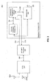
- FIG. 2 illustrates an example user equipment (UE) 200 in which embodiments can be implemented or practiced.
- Example UE 200 is provided for the purpose of illustration only and is not limiting of embodiments.
- Example UE 200 can be an embodiment of UE 104a, for example.
- example UE 200 includes, without limitation, a plurality of antennas 202a-b, a radio frequency integrated circuit (RFIC) 204, a Fast Fourier Transform (FFT)/Inverse FFT (IFFT) processor 208, and a baseband processor 210.
- FFT/IFFT processor 208 can be implemented within baseband processor 210.
- Baseband processor 210 includes, without limitation, a channel estimation module 216, an interference management module 218, and a demodulator 220.
- example UE 200 can receive transmissions from one or more cells using antennas 202a-b. In other embodiments, UE 200 can have more or less than two antennas.
- the signals received by antennas 202a and 202b are processed by RFIC 204, which may filter, down-convert, and digitize the received signals and then provide the signals in the form of baseband signals to FFT/IFFT processor 208 via an interface 206.
- the received signals can include a desired signal from a serving cell of UE 200 (the serving cell is a cell that transmits a signal intended to the UE) and/or one or more signals from one or more other cells.
- the one or more other cells can be serving cells or non-serving (interfering) cells.
- the desired signal and/or the one or more other signals can include data, pilot, and/or control (signaling) information from the respective cells.
- FFT/IFFT processor 208 processes the baseband signals from RFIC 204 to generate an information signal 212.
- information signal 212 is provided to channel estimation module 216, interference management module 218, and demodulator 220.
- channel estimation module 216 can process information signal 212 to generate estimate(s) of downlink channel(s) from the serving cell and/or any present interfering cells. For example, channel estimation module 216 can generate estimates corresponding to the terms H 1 , H 2 , and H 3 described in equation (1) above when used in example environment 100. In an embodiment, channel estimation module 216 provides generated channel estimates by means of an output signal 224 to interference management module 218.
- interference management module 218 is configured to compute precoders (precoder matrix indicators (PMIs)) for the serving cell and/or any present interfering cells based on the channel estimates contained in output signal 224.
- precoders precoder matrix indicators (PMIs)
- interference management module 218 is configured to select, based on the channel estimates contained in output signal 224, a cell combination from the serving cell and any present interfering cells to participate in joint transmission to UE 200 (in joint transmission, all participating cells transmit the same desired signal to the UE); and to determine a joint PMI for use by the selected cell combination in transmission to UE 200.
- PMIs precoder matrix indicators
- interference management module 218 is configured to decompose an estimate of the downlink channel from the serving cell (or another cell) to generate a left singular matrix and to form a quantized left singular matrix for signaling to the network (the network can use the quantized left singular matrix to determine the precoders for the serving cell and/or any present interfering cells).
- interference management module 218 is configured to output a signal 214 to FFT/IFFT processor 208.
- Signal 214 can include the computed PMIs, the selected cell combination, the joint PMI, and/or the quantized left singular matrix for signaling to the network.
- Signal 214 is processed by FFT/IFFT processor 208 and RFIC 204 and then transmitted by the plurality of antennas 202a-b to a network entity (e.g., the serving cell).
- interference management module 218 is configured to receive an interference correlation matrix index from a network entity (e.g., the serving cell) via information signal 212 and to compute an interference covariance matrix based on the interference correlation matrix index.
- the interference correlation matrix index indicates the interference covariance matrix from a codebook available at UE 200 as described below.
- Interference management module 218 provides the interference covariance matrix by means of a signal 226 to demodulator 220. Using the interference covariance matrix, demodulator 220 can demodulate the desired signal from the serving cell to generate a demodulated desired signal 222.
- FIGs. 3-8 illustrate example processes according to embodiments. These example processes are provided for the purpose of illustration only and are not limiting of embodiments. For the purpose of illustration, the example processes are described with reference to example environment 100 and example UE 200.
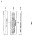
- FIG. 3 illustrates an example process 300 for enabling alignment of interference at UE 200.
- Example process 300 exploits the fact that the UE is better equipped than the network to estimate the downlink channels from the serving cell and any present interfering cells, and as such can determine better downlink transmission precoders than the network.
- Example process 300 also avoids having the UE signal the downlink channel estimates to the network, which can result in a large signaling overhead.
- process 300 begins in step 302, which includes generating first and second channel estimates from first and second interfering cells.
- first and second channel estimates from the first and second interfering cells correspond to the terms H 2 and H 3 in equation (1) described above.
- step 302 is performed by a channel estimation module, such as channel estimation module 216.
- Process 300 then proceeds to step 304, which includes computing first and second precoder matrix indicators (PMIs) for the first and second interfering cells respectively based on the first and second channel estimates, where the first and second PMIs substantially align first and second interfering signals received from the first and second interfering cells.
- PMIs precoder matrix indicators
- the first and second PMIs substantially align first and second interfering signals received from the first and second interfering cells.
- a desired signal from the serving cell can be received in another (e.g., orthogonal) receive direction with no or minimal interference.
- the first and second PMIs correspond respectively to the terms W 2 and W 3 in equation (1) described above
- the first and second interfering signals correspond respectively to the terms H 2 W 2 x 2 and H 3 W 3 x 3 in equation (1).
- step 304 is performed by an interference management module, such as interference management module 218.
- process 300 further includes selecting the first and second interfering cells from multiple available cells. For example, if more than two interfering cells are present, the interference management module can determine which two of the multiple available cells to align interference from. In an embodiment, the interference management module determines for all possible two-cell combinations the potential interference alignment that can be achieved and selects the two cells for which interference can be best aligned.
- the first and second PMIs selected according to equation (4) represent two PMIs from the finite set of PMIs that best meet equation (3).
- the first and second PMIs selected according to equation (4) cause the first and second interfering signals to have receive directions that are as close as possible.
- Process 300 terminates in step 306, which includes signaling the first and second PMIs to a network entity (e.g., serving cell or an interfering cell).
- a network entity e.g., serving cell or an interfering cell.
- the first and second PMIs are signaled on an uplink control channel to one of the available cells (e.g., the serving cell).
- step 306 is performed by antennas 202a-b.
- FIG. 4 illustrates an example process 400 for interference avoidance at UE 200.
- Example process 400 again exploits the fact that the UE is better equipped than the network to estimate the downlink channels from the serving cell and any present interfering cells, and as such can determine better downlink transmission precoders than the network.
- Example process 400 also avoids having the UE signal the downlink channel estimates to the network, which can result in a large signaling overhead.
- process 400 begins in step 402, which includes generating first and second channel estimates from first and second interfering cells.
- first and second channel estimates from the first and second interfering cells correspond to the terms H 2 and H 3 in equation (1) described above.
- step 402 is performed by a channel estimation module, such as channel estimation module 216.
- Process 400 then proceeds to step 404, which includes computing first and second precoder matrix indicators (PMIs) for the first and second interfering cells respectively based on the first and second channel estimates, where the first and second PMIs individually minimize/reduce respectively first and second interfering signals from the first and second interfering cells.
- step 404 is performed by an interference management module, such as interference management module 218.
- Process 400 terminates in step 406, which includes signaling the first and second PMIs to a network entity.
- the first and second PMIs are signaled on an uplink control channel to one of the available cells (e.g., the serving cell).
- step 406 is performed by antennas 202a-b.
- FIG. 5 illustrates another example process 500 for interference avoidance at UE 200.
- Example process 500 again exploits the fact that the UE is better equipped than the network to estimate the downlink channels from the serving cell and any present interfering cells, and as such can determine better downlink transmission precoders than the network.
- Example process 500 also avoids having the UE signal the downlink channel estimates to the network, which can result in a large signaling overhead.
- process 500 begins in step 502, which includes generating a channel estimate from a serving cell and first and second channel estimates from first and second interfering cells.
- the channel estimate from the serving cell corresponds to the term H 1 and the first and second channel estimates from the first and second interfering cells correspond to the terms H 2 and H 3 in equation (1) described above.
- step 502 is performed by a channel estimation module, such as channel estimation module 216.
- Process 500 then proceeds to step 504, which includes computing a precoder matrix indicator (PMI) for the serving cell and first and second PMIs for the first and second interfering cells, where the PMI and the first and second PMIs increase/maximize a data throughput of UE 200.
- step 504 is performed by an interference management module, such as interference management module 218.
- i opt , j opt , k opt correspond respectively to indices of the PMI and the first and second PMIs (from the finite PMI set)
- I corresponds to an identity matrix
- H 1 corresponds to the channel estimate from the serving cell
- H 2 corresponds to the first channel estimate from the first interfer
- the interference management module repeats step 504 for different hypotheses of serving cell and first and second interfering cells and selects the hypothesis (and PMIs) that results in maximum throughput for signaling to the network. This can include selecting the serving cell and the first and second interfering from multiple available cells. If the hypothesis that results in the maximum throughput includes any interfering cell as the serving cell, then UE 200 can request from the network to switch its serving cell according to the hypothesis.
- Process 500 terminates in step 506, which includes signaling the first and second PMIs to a network entity.
- the first and second PMIs are signaled on an uplink control channel to one of the available cells (e.g., the serving cell).
- step 506 is performed by antennas 202a-b.
- FIG. 6 illustrates an example process 600 for enabling joint transmission from a plurality of cells to UE 200.
- Example process 600 again exploits the fact that the UE is better equipped than the network to estimate the downlink channels from the serving cell and any present interfering cells, and as such can determine better downlink transmission precoders than the network to enable joint transmission.
- Example process 600 also avoids having the UE signal the downlink channel estimates to the network, which can result in a large signaling overhead.
- process 600 begins in step 602, which includes selecting a joint transmission level.
- the joint transmission level determines a number of cells (e.g., 2, 3, etc.) of multiple available cells to participate in the joint transmission to the UE.
- step 602 is performed by an interference management module, such as interference management module 218.
- process 600 proceeds to step 604, which includes determining whether all cell combinations have been checked. If the answer is no, process 600 proceeds to step 606, which includes choosing a (previously unchecked) cell combination from among the multiple available cells according to the selected joint transmission level. Then, process 600 proceeds to step 608, which includes determining a joint PMI for the cell combination, where the joint PMI maximizes a signal strength of a joint transmission from the cell combination. Subsequently, step 610 includes determining whether the signal strength associated with the cell combination corresponds to a maximum signal strength over all cell combinations checked thus far. If the answer is no, process 600 returns to step 604. Otherwise, process 600 proceeds to step 612, which includes setting the cell combination as a selected cell combination, and then returns to step 604. In an embodiment, steps 606, 608, 610, and 612 are performed by an interference management module, such as interference management module 218.
- an interference management module such as interference management module 218.
- the selected joint transmission level is equal to 2 and the selected cell combination includes first and second cells of the multiple available cells.
- step 614 includes signaling the selected cell combination and its corresponding joint PMI to a network entity.
- step 614 is performed by antennas 202a-b of UE 200.
- FIG. 7 illustrates an example process 700 for feedback signaling of receive directions from a UE to a network entity according to an embodiment.
- example process 700 is described with reference to the serving cell of the UE.
- process 700 can be used for any available cell, including an interfering cell, for example.
- Example process 700 recognizes that the network typically has or can estimate all the information necessary to determine a precoder (e.g., optimal precoder) for a serving cell (and/or an interfering cell) (e.g., to achieve interference alignment, interference avoidance, or joint transmission at the UE), except for the receive directions provided by the channel from the serving cell (and/or an interfering cell) to the UE.
- a precoder e.g., optimal precoder
- a serving cell and/or an interfering cell
- an interfering cell e.g., to achieve interference alignment, interference avoidance, or joint transmission at the UE
- Example process 700 further recognizes that the receive directions are readily available at the UE and can be given by the principal columns of a left singular matrix, which can be obtained by decomposing (e.g., singular value decomposing) an estimate H of the channel into a product UDV * , where U denotes the left singular matrix, D denotes a diagonal matrix, and V * denotes the conjugate of a right singular matrix of H.
- decomposing e.g., singular value decomposing
- example process 700 enables efficient signaling of the receive directions from the UE to the network, so that the network can re-construct an estimate of the downlink channel H and compute an appropriate precoder for the serving cell (and/or any interfering cell) based on the channel estimate.
- CQI Channel Quality Indicator
- process 700 begins in step 702, which includes generating a channel estimate from a serving cell.
- step 702 can be performed by a channel estimation module, such as channel estimation module 216.
- step 704 includes decomposing the channel estimate to generate a left singular matrix.
- step 704 is performed by an interference management module, such as interference management module 218.
- the interference management module performs a singular value decomposition (SVD) of the channel estimate to generate the left singular matrix.
- SSVD singular value decomposition
- process 700 includes quantizing the left singular matrix to generate a quantized left singular matrix.
- the quantized left singular matrix is a compressed form of the left singular matrix and can be signaled to the network with much lower overhead than the original left singular matrix.
- the quantized left singular matrix reduces an error between the channel estimate and a network version of the channel estimate (a channel estimate constructed at the network side).
- U opt corresponds to the quantized left singular matrix
- C corresponds to a set of possible left singular matrix quantizations of the left singular matrix
- U corresponds to a left singular matrix quantization from the set C
- H corresponds to the channel estimate at the UE
- SNR(CQI) corresponds to an estimate of signal-to-noise ratio (SNR) at the UE
- V correspond
- Equation (8) thus selects the quantization of U from the set of possible quantizations to reduce or minimize the difference between the channel estimate at the UE and the channel estimate that would be constructed by the network.
- Process 700 terminates in step 708, which includes signaling the quantized left singular matrix to a network entity.
- step 614 is performed by antennas 202a-b of UE 200.
- the network can construct a channel estimate as described above using the quantized left singular matrix and then determine the appropriate precoder for the serving cell (and/or an interfering cell) to enable interference management at the UE.
- FIG. 8 illustrates an example process 800 for interference management at a UE based on feedforward signaling of interference covariance information from a network entity.
- the UE can perform interference suppression with knowledge of the interference covariance matrix Q.
- the UE does not know the interference covariance matrix and cannot estimate it with good accuracy, and signaling the interference covariance matrix to the UE can consume significant resources.
- the interference correlation matrix can be signaled to the UE with as low as a single bit in some embodiments as further described below.
- process 800 begins in step 802, which includes receiving an interference correlation matrix index from a network entity.
- the interference correlation matrix index includes one or more bits that indicate an interference correlation matrix from a finite set of interference correlation matrices.
- the finite set of interference correlation matrices can be represented by a codebook, which as further described below can be reduced in size by exploiting the knowledge of the antenna structure of the UE.
- the network signals the interference correlation matrix index that corresponds to the interference correlation matrix quantization that is closest to the actual interference correlation matrix.
- the UE can reliably estimate the magnitude
- compression of the codebook can be achieved by exploiting the physical structure of the antennas at the UE.
- ULA Uniform Linear Array
- DFT Discrete Fourier Transform
- the received signals across the antennas are only phase shifted by ⁇ relative to each other.
- the interference correlation matrix can be signaled to the UE by signaling only the phase angle ⁇ for a ULA antenna structure and by signaling ⁇ and c for a cross-polarized antenna structure.
- the interference correlation matrix index is selected by the network from a codebook table, as illustrated by Table 1 below, for example.
- the codebook specifies a corresponding interference management approach to be used by the UE.
- the interference management approach specifies an interference correlation matrix to be applied by the UE.
- index value 1 provides that the UE uses its own interference management implementation (without relying on network assistance) and to further turn off noise correlation estimation.
- the network may signal index value 1 to the UE when the actual interference covariance matrix is not sufficiently close to any quantization (of the interference covariance matrix) available at the UE, such that the UE's accounting for noise estimation can degrade the UE's performance.
- Index value 3 indicates to the UE to use an interference correlation matrix for cross-polarized antenna structures (which corresponds to the physical antenna structure of the UE), which is indexed by the value 1.
- the UE can retrieve the interference correlation matrix corresponding to the signaled index from a memory and apply it in demodulation.
- Cross Polarized Structure 1 4
- Cross Polarized Structure 2 : : Cross Polarized Structure n ULA Structure 1
- ULA Structure 2 ULA Structure n Hybrid Structure 1 Hybrid Structure 2 : Hybrid Structure n
- the signaling of the interference correlation matrix index from the network to the UE can be further compressed by first signaling the physical antenna structure and subsequently signaling only an index from a compressed codebook dedicated for the signaled physical antenna structure.
- the network can signal a receive combining method and/or receiver combining coefficients to the UE.
- An example codebook according to this embodiment is given by Table 2 below. Similar to Table 1, Table 2 provides a fallback option, indexed by index value 1, in which the UE is instructed to determine its own receive combiner. Additionally, Table 2 includes entries in which the UE can be instructed to compute its receive combiner based on CSI-RS (Channel State Information - Reference Signal) measurements, with the UE further provided which CSI-RS resources correspond to interference. Explicit signaling of receive combiners is also enabled by Table 2. As described above with respect to Table 1, receiver combiners based on physical antenna structures can be used.
- CSI-RS Channel State Information - Reference Signal
- step 804 includes determining an interference correlation matrix based on the interference correlation matrix index.
- the UE can retrieve the interference correlation matrix corresponding to the signaled index from a memory.
- step 806 process 800 includes generating a magnitude matrix from noise power estimates.
- the magnitude matrix corresponds to the matrix M ⁇ , described above, which the UE can estimate with good accuracy from noise power estimates.
- step 808 includes computing an interference covariance matrix using the interference correlation matrix and the magnitude matrix.
- steps 802-808 are performed by an interference management module, such as interference management module 218, for example.
- step 810 includes demodulating a desired signal using the interference covariance matrix.
- step 810 is performed by a demodulator, such as demodulator 220.
Landscapes
- Engineering & Computer Science (AREA)
- Signal Processing (AREA)
- Computer Networks & Wireless Communication (AREA)
- Physics & Mathematics (AREA)
- Mathematical Physics (AREA)
- Mobile Radio Communication Systems (AREA)
Abstract
Description
- The present application claims the benefit of
U.S. Provisional Application No. 61/732,200, filed November 30, 2012 - The present disclosure relates generally to interference management in wireless multi-access communication networks, and more particularly to systems and methods to enable reduction and/or suppression of interference.
- Interference management is significantly important for future cellular communications systems. Typical interference management approaches rely on coordination between base stations in the network and knowledge of full channel state information (CSI) at the network side. In practice, obtaining the full CSI at the network side can consume significant resources as a large amount of information would need to be signaled from the user equipments (UEs) to their serving base stations and also in between base stations.
- According to an aspect, a user equipment (UE) comprises:
- a channel estimation module configured to generate first and second channel estimates from first and second interfering cells;
- an interference management module configured to compute first and second precoder matrix indicators (PMIs) for the first and second interfering cells respectively based on the first and second channel estimates, wherein the first and second PMIs substantially align first and second interfering signals received from the first and second interfering cells; and
- one or more antennas configured to signal the first and second PMIs to a network entity.
- Advantageously, the interference management module is further configured to select the first and second interfering cells from multiple available cells.
- Advantageously, the interference management module is configured to compute the first and second PMIs according to:

where iopt and jopt correspond respectively to indices of the first and second PMIs, H2 corresponds to the first channel estimate from the first interfering cell, H3 corresponds to the second channel estimate from the second interfering cell, Wi corresponds to the first PMI, and Wj corresponds to the second PMI, and 〈 〉 denotes a dot-product operation. - Advantageously, the interference management module is further configured to select a serving cell of the UE and the first and second interfering cells from the multiple available cells.
- Advantageously, the interference management module is further configured to select the serving cell and the first and second interfering cells to increase a data throughput to the UE.
- Advantageously, the interference management module is further configured to compute a PMI for the serving cell and the first and second PMIs according to:
where iopt, jopt, kopt correspond respectively to indices of the PMI and the first and second PMIs, I corresponds to an identity matrix, H1 corresponds to a channel estimate from the serving cell, H2 corresponds to the first channel estimate from the first interfering cell, H3 corresponds to the second channel estimate from the second interfering cell, Wi corresponds to the PMI for the serving cell, Wj corresponds to the first PMI, Wk corresponds to the second PMI, and det() denotes a matrix determinant operation. - Advantageously, the interference management module is further configured to compute at least one of the first and second PMIs to reduce interference from at least one of the first and second interfering cells.
- According to an aspect, a user equipment (UE), comprises:
- a channel estimation module configured to generate channel estimates from multiple available cells;
- an interference management module configured to select a cell combination from the multiple available cells based at least in part on the channel estimates, the cell combination configured to increase a signal strength of a joint transmission from the cell combination to the UE; and
- one or more antennas configured to signal the cell combination to a network entity.
- Advantageously, the interference management module is further configured to select a joint transmission level determining a number of cells of the multiple available cells participating in the joint transmission to the UE.
- Advantageously, a size of the cell combination is equal to the joint transmission level.
- Advantageously, the interference management module is further configured to determine a joint precoder matrix indicator (PMI) for the cell combination.
- Advantageously, the joint PMI maximizes the signal strength of the joint transmission from the cell combination to the UE.
- Advantageously, the cell combination includes first and second cells of the multiple available cells, and wherein the interference management is further configured to select the cell combination and the joint PMI according to:

where iopt and jopt correspond respectively to indices of the first and second cells, k opt corresponds to an index of the joint PMI, Hi corresponds to a first channel estimate from the first cell, Hj corresponds to a second channel estimate from the second cell, and Wk corresponds to the joint PMI. - According to an aspect, a user equipment (UE) comprises:
- a channel estimation module configured to generate a channel estimate from a cell;
- an interference management module configured to decompose the channel estimate to generate a left singular matrix and to quantize the left singular matrix to generate a quantized left singular matrix; and
- one or more antennas configured to signal the quantized left singular matrix to a network entity.
- Advantageously, the quantized left singular matrix reduces an error between the channel estimate and a network version of the channel estimate.
- Advantageously, the interference management module is configured to generate the quantized left singular matrix according to:

where Uopt corresponds to the quantized left singular matrix, C corresponds to a set of possible left singular matrix quantizations of the left singular matrix, U corresponds to a left singular matrix quantization from the set C, H corresponds to the channel estimate, SNR(CQI) corresponds to an estimate of signal-to-noise ratio (SNR) at the UE, and V corresponds to a right singular matrix of the channel estimate. - According to an aspect, a user equipment (UE) comprises:
- an interference management module configured to receive an interference correlation matrix index from a network entity; and compute an interference covariance matrix based at least in part on the interference correlation matrix index; and
- a demodulator configured to demodulate a desired signal using the interference covariance matrix.
- Advantageously, the interference management module is further configured to determine an interference correlation matrix based on the interference correlation matrix index; generate a magnitude matrix from a noise power estimate; and compute the interference covariance matrix using the interference correlation matrix and the magnitude matrix.
- Advantageously, the interference correlation matrix index specifies a correlation coefficient of the interference correlation matrix.
- Advantageously, the UE comprises a plurality of antennas, and wherein the interference correlation matrix index is selected based on a physical structure of the plurality of antennas.
- The accompanying drawings, which are incorporated herein and form a part of the specification, illustrate the present disclosure and, together with the description, further serve to explain the principles of the disclosure and to enable a person skilled in the pertinent art to make and use the disclosure.
-
FIG. 1 illustrates an example environment in which embodiments can be implemented or practiced. -
FIG. 2 illustrates an example user equipment (UE) in which embodiments can be implemented or practiced. -
FIGs. 3-8 illustrate example processes according to embodiments. - The present disclosure will be described with reference to the accompanying drawings. Generally, the drawing in which an element first appears is typically indicated by the leftmost digit(s) in the corresponding reference number.
- For purposes of this discussion, the term "module" shall be understood to include at least one of software, firmware, and hardware (such as one or more circuits, microchips, processors, or devices, or any combination thereof), and any combination thereof. In addition, it will be understood that each module can include one, or more than one, component within an actual device, and each component that forms a part of the described module can function either cooperatively or independently of any other component forming a part of the module. Conversely, multiple modules described herein can represent a single component within an actual device. Further, components within a module can be in a single device or distributed among multiple devices in a wired or wireless manner.
-
FIG. 1 illustrates anexample environment 100 in which embodiments can be implemented or practiced.Example environment 100 is provided for the purpose of illustration only and is not limiting of embodiments. As shown inFIG. 1 ,example environment 100 illustrates a multi-access communication network, which may be a cellular network. The cellular network can operate using existing 3G/4G cellular technology standards (e.g., Long Term Evolution (LTE), Wideband Code Division Multiple Access (WCDMA), WiMAX, etc.) or future 5G cellular technology standards (e.g., LTE-Advanced). - As shown in
FIG. 1 ,example environment 100 includes, without limitation, threecellular regions regions cells - For the purpose of illustration only, it is assumed that
cells region 106a, such that UE 104a receives, in addition to a desiredsignal 108 fromcell 102a, first andsecond interfering signals cells cells signals signal 108. - In an embodiment, the received signal (y) at
UE 104a can be described mathematically as:
where x1, x2, and x3 denote the transmitted signals ofcells cells cells UE 104a respectively; and n denotes noise and inter-cell interference atUE 104a. - In general,
UE 104a can demodulate the transmitted signal x1 (corresponding to desired signal 108) at high performance with knowledge of an interference covariance matrix. With reference to the received signal model above, the interference covariance matrix can be described mathematically as:
where I represents an identity matrix, and * represents a conjugate operator. - However, in practice,
UE 104a is unable to compute an accurate estimate of the interference covariance matrix Q. This is because, in a typical cellular network, interference is highly variable and often unpredictable from one time/frequency allocation to another. Further, the minimum time/frequency allocation granularity contains a low number of resource elements (e.g., a physical resource block (PRB) in LTE contains only 12 tones and 7 Orthogonal Frequency Division Multiplexing (OFDM) symbols), only a few of which carry pilot tones that can be used for interference covariance estimation. Accordingly,UE 104a cannot perform sufficient interference covariance measurements to determine an accurate estimate of the interference covariance matrix Q before interference varies, and can suffer considerable demodulation performance degradation by using a poor estimate of the interference covariance matrix Q. - Embodiments, as further described below, provide systems and methods for interference management in wireless multi-access communication networks, and more particularly systems and methods to enable reduction and/or suppression of interference. Embodiments for interference reduction include, without limitation, systems and methods to enable interference alignment, interference avoidance, and/or joint transmission to a UE. Embodiments for enabling interference suppression include, without limitation, systems and methods for feedback (from a UE to the network) or feedforward (from the network to the UE) signaling to enable interference estimation (e.g., estimation of the interference covariance matrix) at the network/UE.
-
FIG. 2 illustrates an example user equipment (UE) 200 in which embodiments can be implemented or practiced.Example UE 200 is provided for the purpose of illustration only and is not limiting of embodiments.Example UE 200 can be an embodiment ofUE 104a, for example. As shown inFIG. 2 ,example UE 200 includes, without limitation, a plurality ofantennas 202a-b, a radio frequency integrated circuit (RFIC) 204, a Fast Fourier Transform (FFT)/Inverse FFT (IFFT)processor 208, and abaseband processor 210. In another embodiment, FFT/IFFT processor 208 can be implemented withinbaseband processor 210.Baseband processor 210 includes, without limitation, achannel estimation module 216, aninterference management module 218, and ademodulator 220. - In an embodiment,
example UE 200 can receive transmissions from one or morecells using antennas 202a-b. In other embodiments,UE 200 can have more or less than two antennas. The signals received byantennas RFIC 204, which may filter, down-convert, and digitize the received signals and then provide the signals in the form of baseband signals to FFT/IFFT processor 208 via aninterface 206. In embodiments, the received signals can include a desired signal from a serving cell of UE 200 (the serving cell is a cell that transmits a signal intended to the UE) and/or one or more signals from one or more other cells. The one or more other cells can be serving cells or non-serving (interfering) cells. The desired signal and/or the one or more other signals can include data, pilot, and/or control (signaling) information from the respective cells. - FFT/
IFFT processor 208 processes the baseband signals fromRFIC 204 to generate aninformation signal 212. In an embodiment, information signal 212 is provided to channelestimation module 216,interference management module 218, anddemodulator 220. - In an embodiment,
channel estimation module 216 can process information signal 212 to generate estimate(s) of downlink channel(s) from the serving cell and/or any present interfering cells. For example,channel estimation module 216 can generate estimates corresponding to the terms H1 , H2, and H3 described in equation (1) above when used inexample environment 100. In an embodiment,channel estimation module 216 provides generated channel estimates by means of anoutput signal 224 tointerference management module 218. - In an embodiment, as further described below with reference to
FIGs. 3-5 ,interference management module 218 is configured to compute precoders (precoder matrix indicators (PMIs)) for the serving cell and/or any present interfering cells based on the channel estimates contained inoutput signal 224. In another embodiment, as further described below with reference toFIG. 6 ,interference management module 218 is configured to select, based on the channel estimates contained inoutput signal 224, a cell combination from the serving cell and any present interfering cells to participate in joint transmission to UE 200 (in joint transmission, all participating cells transmit the same desired signal to the UE); and to determine a joint PMI for use by the selected cell combination in transmission toUE 200. In a further embodiment, as described below with reference toFIG. 7 ,interference management module 218 is configured to decompose an estimate of the downlink channel from the serving cell (or another cell) to generate a left singular matrix and to form a quantized left singular matrix for signaling to the network (the network can use the quantized left singular matrix to determine the precoders for the serving cell and/or any present interfering cells). - In an embodiment,
interference management module 218 is configured to output asignal 214 to FFT/IFFT processor 208. Signal 214 can include the computed PMIs, the selected cell combination, the joint PMI, and/or the quantized left singular matrix for signaling to the network.Signal 214 is processed by FFT/IFFT processor 208 andRFIC 204 and then transmitted by the plurality ofantennas 202a-b to a network entity (e.g., the serving cell). - In another embodiment, as further described below with reference to
FIG. 8 ,interference management module 218 is configured to receive an interference correlation matrix index from a network entity (e.g., the serving cell) viainformation signal 212 and to compute an interference covariance matrix based on the interference correlation matrix index. In an embodiment, the interference correlation matrix index indicates the interference covariance matrix from a codebook available atUE 200 as described below.Interference management module 218 provides the interference covariance matrix by means of asignal 226 todemodulator 220. Using the interference covariance matrix,demodulator 220 can demodulate the desired signal from the serving cell to generate a demodulated desiredsignal 222. -
FIGs. 3-8 illustrate example processes according to embodiments. These example processes are provided for the purpose of illustration only and are not limiting of embodiments. For the purpose of illustration, the example processes are described with reference toexample environment 100 andexample UE 200. -
FIG. 3 illustrates anexample process 300 for enabling alignment of interference atUE 200.Example process 300 exploits the fact that the UE is better equipped than the network to estimate the downlink channels from the serving cell and any present interfering cells, and as such can determine better downlink transmission precoders than the network.Example process 300 also avoids having the UE signal the downlink channel estimates to the network, which can result in a large signaling overhead. - As shown in
FIG. 3 ,process 300 begins instep 302, which includes generating first and second channel estimates from first and second interfering cells. With reference toexample environment 100, for example, the first and second channel estimates from the first and second interfering cells correspond to the terms H2 and H3 in equation (1) described above. As would be understood by a person of skill in the art, more than two channel estimates can be generated when more than two strong interfering cells are present. In an embodiment,step 302 is performed by a channel estimation module, such aschannel estimation module 216. -
Process 300 then proceeds to step 304, which includes computing first and second precoder matrix indicators (PMIs) for the first and second interfering cells respectively based on the first and second channel estimates, where the first and second PMIs substantially align first and second interfering signals received from the first and second interfering cells. By aligning the first and second interfering signals along one receive direction, a desired signal from the serving cell can be received in another (e.g., orthogonal) receive direction with no or minimal interference. With reference toexample environment 100, for example, the first and second PMIs correspond respectively to the terms W2 and W3 in equation (1) described above, and the first and second interfering signals correspond respectively to the terms H 2 W 2 x 2 and H 3 W 3 x 3 in equation (1). In an embodiment,step 304 is performed by an interference management module, such asinterference management module 218. - In an embodiment,
process 300 further includes selecting the first and second interfering cells from multiple available cells. For example, if more than two interfering cells are present, the interference management module can determine which two of the multiple available cells to align interference from. In an embodiment, the interference management module determines for all possible two-cell combinations the potential interference alignment that can be achieved and selects the two cells for which interference can be best aligned. - In an embodiment, the alignment of the interference from two cells is performed by selecting the first and second PMIs to satisfy:

where H2 and H3 denote the first and second channel estimates respectively, W2 and W3 denote the first and second PMIs, and c is a complex constant. - In another embodiment, the interference management module is configured to select the first and second PMIs from a finite set of PMIs such that:

where iopt and joPt correspond respectively to indices (from the finite set of PMIs) of the selected first and second PMIs, H2 corresponds to the first channel estimate from the first interfering cell, H3 corresponds to the second channel estimate from the second interfering cell, Wi corresponds to the first PMI, and Wj corresponds to the second PMI, and 〈 〉 denotes a dot-product operation. The first and second PMIs selected according to equation (4) represent two PMIs from the finite set of PMIs that best meet equation (3). In other words, the first and second PMIs selected according to equation (4) cause the first and second interfering signals to have receive directions that are as close as possible. -
Process 300 terminates instep 306, which includes signaling the first and second PMIs to a network entity (e.g., serving cell or an interfering cell). In an embodiment, the first and second PMIs are signaled on an uplink control channel to one of the available cells (e.g., the serving cell). In an embodiment,step 306 is performed byantennas 202a-b. -
FIG. 4 illustrates anexample process 400 for interference avoidance atUE 200.Example process 400 again exploits the fact that the UE is better equipped than the network to estimate the downlink channels from the serving cell and any present interfering cells, and as such can determine better downlink transmission precoders than the network.Example process 400 also avoids having the UE signal the downlink channel estimates to the network, which can result in a large signaling overhead. - As shown in
FIG. 4 ,process 400 begins instep 402, which includes generating first and second channel estimates from first and second interfering cells. With reference toexample environment 100, for example, the first and second channel estimates from the first and second interfering cells correspond to the terms H2 and H3 in equation (1) described above. As would be understood by a person of skill in the art, more than two channel estimates can be generated when more than two strong interfering cells are present. In an embodiment,step 402 is performed by a channel estimation module, such aschannel estimation module 216. -
Process 400 then proceeds to step 404, which includes computing first and second precoder matrix indicators (PMIs) for the first and second interfering cells respectively based on the first and second channel estimates, where the first and second PMIs individually minimize/reduce respectively first and second interfering signals from the first and second interfering cells. In an embodiment,step 404 is performed by an interference management module, such asinterference management module 218. - In an embodiment, the interference management module individually minimizes interference from the first and/or second interfering cells by selecting the first and/or second PMIs from a finite set of PMIs according to:

where iopt(j) corresponds to an index (from the finite set of PMIs) of the selected first/second PMI, Hj corresponds to first/second channel estimate, and Wi corresponds to the first/second PMI. -
Process 400 terminates instep 406, which includes signaling the first and second PMIs to a network entity. In an embodiment, the first and second PMIs are signaled on an uplink control channel to one of the available cells (e.g., the serving cell). In an embodiment,step 406 is performed byantennas 202a-b. -
FIG. 5 illustrates anotherexample process 500 for interference avoidance atUE 200.Example process 500 again exploits the fact that the UE is better equipped than the network to estimate the downlink channels from the serving cell and any present interfering cells, and as such can determine better downlink transmission precoders than the network.Example process 500 also avoids having the UE signal the downlink channel estimates to the network, which can result in a large signaling overhead. - As shown in
FIG. 5 ,process 500 begins instep 502, which includes generating a channel estimate from a serving cell and first and second channel estimates from first and second interfering cells. With reference toexample environment 100, for example, the channel estimate from the serving cell corresponds to the term H1 and the first and second channel estimates from the first and second interfering cells correspond to the terms H2 and H3 in equation (1) described above. In an embodiment,step 502 is performed by a channel estimation module, such aschannel estimation module 216. -
Process 500 then proceeds to step 504, which includes computing a precoder matrix indicator (PMI) for the serving cell and first and second PMIs for the first and second interfering cells, where the PMI and the first and second PMIs increase/maximize a data throughput ofUE 200. In an embodiment,step 504 is performed by an interference management module, such asinterference management module 218. - In an embodiment, the interference management module is configured to select the PMI and the first and second PMIs from a finite PMI set according to:

where iopt, jopt, kopt correspond respectively to indices of the PMI and the first and second PMIs (from the finite PMI set), I corresponds to an identity matrix, H1 corresponds to the channel estimate from the serving cell, H2 corresponds to the first channel estimate from the first interfering cell, H3 corresponds to the second channel estimate from the second interfering cell, W¡ corresponds to the PMI for the serving cell, Wj corresponds to the first PMI, Wk corresponds to the second PMI, and det() denotes a matrix determinant operation. - In another embodiment, the interference management module repeats
step 504 for different hypotheses of serving cell and first and second interfering cells and selects the hypothesis (and PMIs) that results in maximum throughput for signaling to the network. This can include selecting the serving cell and the first and second interfering from multiple available cells. If the hypothesis that results in the maximum throughput includes any interfering cell as the serving cell, thenUE 200 can request from the network to switch its serving cell according to the hypothesis. -
Process 500 terminates instep 506, which includes signaling the first and second PMIs to a network entity. In an embodiment, the first and second PMIs are signaled on an uplink control channel to one of the available cells (e.g., the serving cell). In an embodiment,step 506 is performed byantennas 202a-b. -
FIG. 6 illustrates anexample process 600 for enabling joint transmission from a plurality of cells toUE 200.Example process 600 again exploits the fact that the UE is better equipped than the network to estimate the downlink channels from the serving cell and any present interfering cells, and as such can determine better downlink transmission precoders than the network to enable joint transmission.Example process 600 also avoids having the UE signal the downlink channel estimates to the network, which can result in a large signaling overhead. - As shown in
FIG. 6 ,process 600 begins instep 602, which includes selecting a joint transmission level. The joint transmission level determines a number of cells (e.g., 2, 3, etc.) of multiple available cells to participate in the joint transmission to the UE. In an embodiment,step 602 is performed by an interference management module, such asinterference management module 218. - Subsequently,
process 600 proceeds to step 604, which includes determining whether all cell combinations have been checked. If the answer is no,process 600 proceeds to step 606, which includes choosing a (previously unchecked) cell combination from among the multiple available cells according to the selected joint transmission level. Then,process 600 proceeds to step 608, which includes determining a joint PMI for the cell combination, where the joint PMI maximizes a signal strength of a joint transmission from the cell combination. Subsequently,step 610 includes determining whether the signal strength associated with the cell combination corresponds to a maximum signal strength over all cell combinations checked thus far. If the answer is no,process 600 returns to step 604. Otherwise,process 600 proceeds to step 612, which includes setting the cell combination as a selected cell combination, and then returns to step 604. In an embodiment, steps 606, 608, 610, and 612 are performed by an interference management module, such asinterference management module 218. - In another embodiment, the selected joint transmission level is equal to 2 and the selected cell combination includes first and second cells of the multiple available cells. In an embodiment, the interference management module is configured to select the cell combination and the joint PMI according to:

where iopt and jopt correspond respectively to indices of the first and second cells, k opt corresponds to an index of the joint PMI from a finite PMI set, Hi corresponds to a first channel estimate from the first cell, Hj corresponds to a second channel estimate from the second cell, and Wk corresponds to the joint PMI. - Returning to step 604, if all cell combinations have been checked,
process 600 proceeds to step 614, which includes signaling the selected cell combination and its corresponding joint PMI to a network entity. In an embodiment,step 614 is performed byantennas 202a-b ofUE 200. -
FIG. 7 illustrates anexample process 700 for feedback signaling of receive directions from a UE to a network entity according to an embodiment. For the purpose of illustration only,example process 700 is described with reference to the serving cell of the UE. However, as further described below,process 700 can be used for any available cell, including an interfering cell, for example. -
Example process 700 recognizes that the network typically has or can estimate all the information necessary to determine a precoder (e.g., optimal precoder) for a serving cell (and/or an interfering cell) (e.g., to achieve interference alignment, interference avoidance, or joint transmission at the UE), except for the receive directions provided by the channel from the serving cell (and/or an interfering cell) to the UE.Example process 700 further recognizes that the receive directions are readily available at the UE and can be given by the principal columns of a left singular matrix, which can be obtained by decomposing (e.g., singular value decomposing) an estimate H of the channel into a product UDV *, where U denotes the left singular matrix, D denotes a diagonal matrix, and V * denotes the conjugate of a right singular matrix of H. Recognizing further that the network can compute good approximations of D and V * from Channel Quality Indicator (CQI) reports from the UE,example process 700 enables efficient signaling of the receive directions from the UE to the network, so that the network can re-construct an estimate of the downlink channel H and compute an appropriate precoder for the serving cell (and/or any interfering cell) based on the channel estimate. - As shown in
FIG. 7 ,process 700 begins instep 702, which includes generating a channel estimate from a serving cell. As discussed above, step 702 can be performed by a channel estimation module, such aschannel estimation module 216. - Subsequently,
process 700 proceeds to step 704, which includes decomposing the channel estimate to generate a left singular matrix. In an embodiment,step 704 is performed by an interference management module, such asinterference management module 218. In an embodiment, the interference management module performs a singular value decomposition (SVD) of the channel estimate to generate the left singular matrix. - Then, in
step 706,process 700 includes quantizing the left singular matrix to generate a quantized left singular matrix. In an embodiment, the quantized left singular matrix is a compressed form of the left singular matrix and can be signaled to the network with much lower overhead than the original left singular matrix. In another embodiment, the quantized left singular matrix reduces an error between the channel estimate and a network version of the channel estimate (a channel estimate constructed at the network side). - In an embodiment, the interference management module is configured to generate the quantized left singular matrix according to:

where Uopt corresponds to the quantized left singular matrix, C corresponds to a set of possible left singular matrix quantizations of the left singular matrix, U corresponds to a left singular matrix quantization from the set C, H corresponds to the channel estimate at the UE, SNR(CQI) corresponds to an estimate of signal-to-noise ratio (SNR) at the UE, and V corresponds to a right singular matrix of the channel estimate. Note that in equation (8), the term U*SNR(cqi)*V* corresponds to the network version of the channel estimate, which can be constructed by the network based on the quantized left singular matrix signaled by the UE and approximations of the matrices D and V *. Equation (8) thus selects the quantization of U from the set of possible quantizations to reduce or minimize the difference between the channel estimate at the UE and the channel estimate that would be constructed by the network. -
Process 700 terminates instep 708, which includes signaling the quantized left singular matrix to a network entity. In an embodiment,step 614 is performed byantennas 202a-b ofUE 200. The network can construct a channel estimate as described above using the quantized left singular matrix and then determine the appropriate precoder for the serving cell (and/or an interfering cell) to enable interference management at the UE. -
FIG. 8 illustrates anexample process 800 for interference management at a UE based on feedforward signaling of interference covariance information from a network entity. As described above, the UE can perform interference suppression with knowledge of the interference covariance matrix Q. However, typically, the UE does not know the interference covariance matrix and cannot estimate it with good accuracy, and signaling the interference covariance matrix to the UE can consume significant resources.Example process 800 recognizes that the covariance interference matrix can be decomposed as Q = M 1/ 2Q 1/2 where M is a magnitude matrix (contains noise power estimates on the diagonal) and C is an interference correlation matrix.Example process 800 further recognizes that the magnitude matrix M can be estimated at the UE with reasonable accuracy, and that the UE can construct an interference covariance matrix estimate as Q̂ = M̂ 1/ 2CM̂ 1/ 2, where M̂ is the UE's estimate of the magnitude matrix. Signaling of the interference correlation matrix (or a quantization thereof) from the network is therefore all that the UE needs to generate the interference covariance matrix estimate. By sharing a codebook for the interference correlation matrix between the network and the UE, and by further exploiting knowledge of the physical antenna structure of the UE (when known at the network), the interference correlation matrix can be signaled to the UE with as low as a single bit in some embodiments as further described below. - As shown in
FIG. 8 ,process 800 begins instep 802, which includes receiving an interference correlation matrix index from a network entity. In an embodiment, the interference correlation matrix index includes one or more bits that indicate an interference correlation matrix from a finite set of interference correlation matrices. The finite set of interference correlation matrices can be represented by a codebook, which as further described below can be reduced in size by exploiting the knowledge of the antenna structure of the UE. In an embodiment, the network signals the interference correlation matrix index that corresponds to the interference correlation matrix quantization that is closest to the actual interference correlation matrix. - In an embodiment, for a UE with two receive antennas, the interference correlation matrix C is given by:

where ρ is a complex correlation coefficient number. In some cases, the UE can reliably estimate the magnitude |ρ| of ρ, and thus in an embodiment the network only signals a phase θ of ρ in order to convey the interference correlation matrix C to the UE. In another embodiment, the correlation matrix C can have (N2-N)/2 unique possible complex numbers (with magnitude <= 1), where N is the number of receive antennas. As such, the possible complex numbers are quantized, and the interference correlation matrix index signals one quantization from the quantized complex numbers. - In another embodiment, for a UE with more than two antennas, compression of the codebook can be achieved by exploiting the physical structure of the antennas at the UE. For example, for a Uniform Linear Array (ULA) antenna structure, embodiments exploit the fact that the principal receive and transmit directions of the downlink channel to the UE (which are given by the left singular matrix and the right singular matrix respectively of the channel) can be closely approximated by a Discrete Fourier Transform (DFT) vector as follows:

where θ represents a phase angle, and N represents the number of antennas. In other words, the received signals across the antennas are only phase shifted by θ relative to each other. For cross-polarized antenna structures, there is additionally a phase difference across polarization, and the eigenmode of the channel component within the polarization can be approximated by a DFT vector and has the following structure:
- Thus, the interference correlation matrix can be signaled to the UE by signaling only the phase angle θ for a ULA antenna structure and by signaling θ and c for a cross-polarized antenna structure.
- In an embodiment, the interference correlation matrix index is selected by the network from a codebook table, as illustrated by Table 1 below, for example. As shown in Table 1, for each index value, the codebook specifies a corresponding interference management approach to be used by the UE. In some cases, the interference management approach specifies an interference correlation matrix to be applied by the UE. For example, index value 1 provides that the UE uses its own interference management implementation (without relying on network assistance) and to further turn off noise correlation estimation. The network may signal index value 1 to the UE when the actual interference covariance matrix is not sufficiently close to any quantization (of the interference covariance matrix) available at the UE, such that the UE's accounting for noise estimation can degrade the UE's performance. Index value 3 indicates to the UE to use an interference correlation matrix for cross-polarized antenna structures (which corresponds to the physical antenna structure of the UE), which is indexed by the value 1. The UE can retrieve the interference correlation matrix corresponding to the signaled index from a memory and apply it in demodulation.
Table 1 Index Covariance Method 1 UE Implementation, Turn off Noise Correlation 2 UE Implementation, Turn on Noise Correlation 3 Cross Polarized Structure 1 4 Cross Polarized Structure 2 : : Cross Polarized Structure n ULA Structure 1 ULA Structure 2 : ULA Structure n Hybrid Structure 1 Hybrid Structure 2 : Hybrid Structure n - As would be understood by a person of skill in the art, in other embodiments, the signaling of the interference correlation matrix index from the network to the UE can be further compressed by first signaling the physical antenna structure and subsequently signaling only an index from a compressed codebook dedicated for the signaled physical antenna structure.
- In another embodiment, instead of signaling the interference correlation matrix, the network can signal a receive combining method and/or receiver combining coefficients to the UE. An example codebook according to this embodiment is given by Table 2 below. Similar to Table 1, Table 2 provides a fallback option, indexed by index value 1, in which the UE is instructed to determine its own receive combiner. Additionally, Table 2 includes entries in which the UE can be instructed to compute its receive combiner based on CSI-RS (Channel State Information - Reference Signal) measurements, with the UE further provided which CSI-RS resources correspond to interference. Explicit signaling of receive combiners is also enabled by Table 2. As described above with respect to Table 1, receiver combiners based on physical antenna structures can be used.
Table 2 Index Receive Combining Method 1 UE Implementation 2 Based on CSI-RS, CSI-RS Bitmap 1 3 Based on CSI-RS, CSI-RS Bitmap : Based on CSI-RS, CSI-RS Bitmap n : Receive Combiner 1 Receive Combiner 2 : : : Receive Combiner n - Returning to
FIG. 8 , afterstep 802,process 800 proceeds to step 804, which includes determining an interference correlation matrix based on the interference correlation matrix index. As described above, the UE can retrieve the interference correlation matrix corresponding to the signaled index from a memory. Subsequently, instep 806,process 800 includes generating a magnitude matrix from noise power estimates. In an embodiment, the magnitude matrix corresponds to the matrix M̂, described above, which the UE can estimate with good accuracy from noise power estimates.Process 800 then proceeds to step 808, which includes computing an interference covariance matrix using the interference correlation matrix and the magnitude matrix. In an embodiment, the interference covariance matrix is computed as Q̂ = M̂ 1/2 CM̂ 1/2, where C is the interference correlation matrix determined instep 804. In an embodiment, steps 802-808 are performed by an interference management module, such asinterference management module 218, for example. - With the interference covariance matrix computed in
step 808,process 800 terminates instep 810, which includes demodulating a desired signal using the interference covariance matrix. In an embodiment,step 810 is performed by a demodulator, such asdemodulator 220. - Embodiments have been described above with the aid of functional building blocks illustrating the implementation of specified functions and relationships thereof. The boundaries of these functional building blocks have been arbitrarily defined herein for the convenience of the description. Alternate boundaries can be defined so long as the specified functions and relationships thereof are appropriately performed.
- The foregoing description of the specific embodiments will so fully reveal the general nature of the disclosure that others can, by applying knowledge within the skill of the art, readily modify and/or adapt for various applications such specific embodiments, without undue experimentation, without departing from the general concept of the present disclosure. Therefore, such adaptations and modifications are intended to be within the meaning and range of equivalents of the disclosed embodiments, based on the teaching and guidance presented herein. It is to be understood that the phraseology or terminology herein is for the purpose of description and not of limitation, such that the terminology or phraseology of the present specification is to be interpreted by the skilled artisan in light of the teachings and guidance.
- The breadth and scope of embodiments of the present disclosure should not be limited by any of the above-described exemplary embodiments as other embodiments will be apparent to a person of skill in the art based on the teachings herein.
Claims (15)
- A user equipment (UE), comprising:a channel estimation module configured to generate first and second channel estimates from first and second interfering cells;an interference management module configured to compute first and second precoder matrix indicators (PMIs) for the first and second interfering cells respectively based on the first and second channel estimates, wherein the first and second PMIs substantially align first and second interfering signals received from the first and second interfering cells; andone or more antennas configured to signal the first and second PMIs to a network entity.
- The UE of claim 1, wherein the interference management module is further configured to select the first and second interfering cells from multiple available cells.
- The UE of claim 1 or 2, wherein the interference management module is configured to compute the first and second PMIs according to:
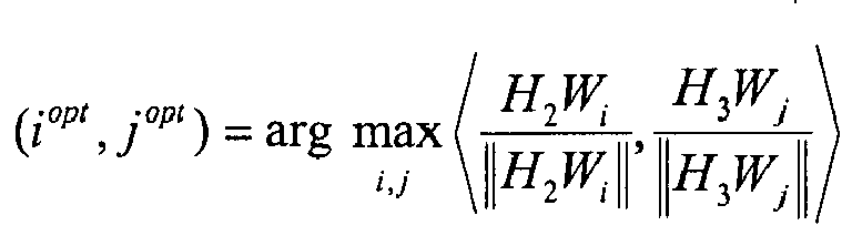
where iopt and jopt correspond respectively to indices of the first and second PMIs, H2 corresponds to the first channel estimate from the first interfering cell, H3 corresponds to the second channel estimate from the second interfering cell, Wi corresponds to the first PMI, and Wj corresponds to the second PMI, and 〈 〉 denotes a dot-product operation. - The UE of any of claims 2 or 3, wherein the interference management module is further configured to select a serving cell of the UE and the first and second interfering cells from the multiple available cells.
- The UE of claim 4, wherein the interference management module is further configured to select the serving cell and the first and second interfering cells to increase a data throughput to the UE.
- The UE of claim 4 or 5, wherein the interference management module is further configured to compute a PMI for the serving cell and the first and second PMIs according to:

where iopt, jopt, kopt correspond respectively to indices of the PMI and the first and second PMIs, I corresponds to an identity matrix, H1 corresponds to a channel estimate from the serving cell, H2 corresponds to the first channel estimate from the first interfering cell, H3 corresponds to the second channel estimate from the second interfering cell, W¡ corresponds to the PMI for the serving cell, Wj corresponds to the first PMI, Wk corresponds to the second PMI, and det() denotes a matrix determinant operation. - The UE of any preceding claim, wherein the interference management module is further configured to compute at least one of the first and second PMIs to reduce interference from at least one of the first and second interfering cells.
- A user equipment (UE), comprising:a channel estimation module configured to generate channel estimates from multiple available cells;an interference management module configured to select a cell combination from the multiple available cells based at least in part on the channel estimates, the cell combination configured to increase a signal strength of a joint transmission from the cell combination to the UE; andone or more antennas configured to signal the cell combination to a network entity.
- The UE of claim 8, wherein the interference management module is further configured to select a joint transmission level determining a number of cells of the multiple available cells participating in the joint transmission to the UE.
- The UE of claim 9, wherein a size of the cell combination is equal to the joint transmission level.
- The UE of any of claims 8 to 10, wherein the interference management module is further configured to determine a joint precoder matrix indicator (PMI) for the cell combination.
- The UE of claim 11, wherein the joint PMI maximizes the signal strength of the joint transmission from the cell combination to the UE.
- The UE of claim 11 or 12, wherein the cell combination includes first and second cells of the multiple available cells, and wherein the interference management is further configured to select the cell combination and the joint PMI according to:

where iopt and jopt correspond respectively to indices of the first and second cells, k opt corresponds to an index of the joint PMI, Hi corresponds to a first channel estimate from the first cell, Hj corresponds to a second channel estimate from the second cell, and Wk corresponds to the joint PMI. - A user equipment (UE), comprising:a channel estimation module configured to generate a channel estimate from a cell;an interference management module configured to decompose the channel estimate to generate a left singular matrix and to quantize the left singular matrix to generate a quantized left singular matrix; andone or more antennas configured to signal the quantized left singular matrix to a network entity.
- A user equipment (UE), comprising:an interference management module configured to receive an interference correlation matrix index from a network entity; and compute an interference covariance matrix based at least in part on the interference correlation matrix index; anda demodulator configured to demodulate a desired signal using the interference covariance matrix.
Applications Claiming Priority (2)
| Application Number | Priority Date | Filing Date | Title |
|---|---|---|---|
| US201261732200P | 2012-11-30 | 2012-11-30 | |
| US14/093,093 US10044487B2 (en) | 2012-11-30 | 2013-11-29 | Interference management in wireless multi-access communication networks |
Publications (3)
| Publication Number | Publication Date |
|---|---|
| EP2738951A2 true EP2738951A2 (en) | 2014-06-04 |
| EP2738951A3 EP2738951A3 (en) | 2014-07-23 |
| EP2738951B1 EP2738951B1 (en) | 2018-03-21 |
Family
ID=49758965
Family Applications (1)
| Application Number | Title | Priority Date | Filing Date |
|---|---|---|---|
| EP13005589.0A Active EP2738951B1 (en) | 2012-11-30 | 2013-12-02 | Interference management in wireless multi-access communication networks |
Country Status (3)
| Country | Link |
|---|---|
| US (1) | US10044487B2 (en) |
| EP (1) | EP2738951B1 (en) |
| CN (1) | CN103856420B (en) |
Cited By (1)
| Publication number | Priority date | Publication date | Assignee | Title |
|---|---|---|---|---|
| CN109891765A (en) * | 2016-11-04 | 2019-06-14 | 高通股份有限公司 | Uplink MIMO design |
Families Citing this family (9)
| Publication number | Priority date | Publication date | Assignee | Title |
|---|---|---|---|---|
| JP6159805B2 (en) | 2012-09-11 | 2017-07-05 | 株式会社Nttドコモ | Method and apparatus for efficient channel state information distribution for MU-MIMO transmission scheme based on old channel state information |
| US9479298B2 (en) | 2013-07-08 | 2016-10-25 | Intel IP Corporation | Demodulation reference signals (DMRS)for side information for interference cancellation |
| WO2016080571A1 (en) * | 2014-11-20 | 2016-05-26 | 엘지전자 주식회사 | Method and device for transmitting and receiving inter-cell information for cancelling inter-cell interference |
| CN106413005A (en) * | 2015-07-27 | 2017-02-15 | 中兴通讯股份有限公司 | Method and device of coordinating cell edge user interference and base station |
| KR102520883B1 (en) * | 2016-07-26 | 2023-04-13 | 삼성전자주식회사 | Apparatus and method for mitigating interference in wirleess communicnation system |
| US10038489B2 (en) | 2017-01-05 | 2018-07-31 | Ceva D.S.P. Ltd. | System and method for adaptive demodulation of cellular device communications |
| US10743201B2 (en) | 2017-01-25 | 2020-08-11 | Ceva D.S.P. Ltd. | System and method for blind detection of transmission parameters of an interfering cell |
| US12395940B2 (en) | 2021-07-14 | 2025-08-19 | Samsung Electronics Co., Ltd. | Hybrid PDSCH for out-of-band earth station interference cancelation |
| US12665622B2 (en) * | 2023-05-11 | 2026-06-23 | Qualcomm Incorporated | Transmitter noise mitigation based on a noise indicator |
Family Cites Families (16)
| Publication number | Priority date | Publication date | Assignee | Title |
|---|---|---|---|---|
| US7191241B2 (en) * | 2002-09-27 | 2007-03-13 | Alacritech, Inc. | Fast-path apparatus for receiving data corresponding to a TCP connection |
| US7475271B2 (en) * | 2003-10-14 | 2009-01-06 | Broadcom Corporation | Exponential channelized timer |
| US8086242B2 (en) | 2007-03-21 | 2011-12-27 | Broadcom Corporation | Method and system for adaptive allocation of feedback resources for CQI and transmit pre-coding |
| US20090110114A1 (en) | 2007-10-26 | 2009-04-30 | Eko Nugroho Onggosanusi | Open-Loop MIMO Scheme and Signaling Support for Wireless Networks |
| CN101400139B (en) | 2008-10-28 | 2010-06-30 | 北京创毅视讯科技有限公司 | Data transmission method and base station in multiple base station collaboration system |
| US20100234071A1 (en) | 2009-03-12 | 2010-09-16 | Comsys Communication & Signal Processing Ltd. | Vehicle integrated communications system |
| CN102356569B (en) * | 2009-03-16 | 2015-06-17 | Lg电子株式会社 | Method and device for supporting carrier aggregation |
| CN101902304B (en) | 2009-05-25 | 2014-10-15 | 株式会社Ntt都科摩 | Channel information feedback method, precoding method, receiving station and sending station |
| US8711716B2 (en) | 2009-06-19 | 2014-04-29 | Texas Instruments Incorporated | Multiple CQI feedback for cellular networks |
| CN101931993B (en) | 2009-06-22 | 2014-09-03 | 华为技术有限公司 | Cell selection method, auxiliary cell selection method, device and communication system |
| KR101568291B1 (en) * | 2009-07-10 | 2015-11-20 | 삼성전자주식회사 | Terminal and base station, and a method of operation of the terminal |
| US8379705B2 (en) * | 2009-08-04 | 2013-02-19 | Qualcomm Incorporated | Hierarchical feedback of channel state information for wireless communication |
| EP2487950B1 (en) * | 2009-10-08 | 2017-06-21 | Fujitsu Limited | Wireless communication system, mobile terminal and collaborative communication method |
| CN102075300B (en) | 2009-11-20 | 2013-12-04 | 富士通株式会社 | Method and device for selecting modulation coding scheme and precoding matrix |
| KR101567018B1 (en) * | 2010-02-09 | 2015-11-06 | 삼성전자주식회사 | System for determining mimo/dsm operating mode based on network backhaul link environment and cooperation level between base stations |
| JP5258002B2 (en) * | 2010-02-10 | 2013-08-07 | マーベル ワールド トレード リミテッド | Device, mobile communication terminal, chipset, and method in MIMO communication system |
-
2013
- 2013-11-29 US US14/093,093 patent/US10044487B2/en active Active
- 2013-12-02 EP EP13005589.0A patent/EP2738951B1/en active Active
- 2013-12-02 CN CN201310637376.9A patent/CN103856420B/en not_active Expired - Fee Related
Non-Patent Citations (1)
| Title |
|---|
| None |
Cited By (3)
| Publication number | Priority date | Publication date | Assignee | Title |
|---|---|---|---|---|
| CN109891765A (en) * | 2016-11-04 | 2019-06-14 | 高通股份有限公司 | Uplink MIMO design |
| EP3535860B1 (en) * | 2016-11-04 | 2022-03-16 | QUALCOMM Incorporated | Uplink mimo design |
| CN109891765B (en) * | 2016-11-04 | 2022-04-01 | 高通股份有限公司 | Uplink MIMO design |
Also Published As
| Publication number | Publication date |
|---|---|
| US10044487B2 (en) | 2018-08-07 |
| US20140153510A1 (en) | 2014-06-05 |
| CN103856420A (en) | 2014-06-11 |
| EP2738951B1 (en) | 2018-03-21 |
| CN103856420B (en) | 2018-03-02 |
| EP2738951A3 (en) | 2014-07-23 |
Similar Documents
| Publication | Publication Date | Title |
|---|---|---|
| EP2738951B1 (en) | Interference management in wireless multi-access communication networks | |
| EP3672099A1 (en) | Methods and apparatuses for codebook restriction for type-ii feedback reporting in a wireless communications network | |
| EP3661069B1 (en) | Method for reporting channel state information, user equipment, and base station | |
| US10700756B2 (en) | User equipment and base station | |
| EP3085042B1 (en) | Adaptive precoding in a mimo wireless communication system | |
| US20190173534A1 (en) | Method for uplink transmisison | |
| EP3444960B1 (en) | Two-stage precoding method and device | |
| US10374836B2 (en) | Method and apparatus for downlink channel estimation in massive MIMO | |
| EP3422760B1 (en) | Channel information reporting method, apparatus and system | |
| KR101664421B1 (en) | Apparatus and method for generating codebook in wireless communication system | |
| US20140185700A1 (en) | Method and apparatus for linear precoding in multi-user multiple-input multiple-output system | |
| US9020058B2 (en) | Precoding feedback for cross-polarized antennas based on signal-component magnitude difference | |
| EP3018852A1 (en) | Method for determining precoding matrix indicator, receiving device and transmitting device | |
| WO2018182381A1 (en) | Method for transmitting uplink data in wireless communication system and apparatus therefor | |
| EP2816739A1 (en) | Aerial calibration method, system and device | |
| EP4170919A1 (en) | Method for feeding back channel state information, user equipment, and base station | |
| EP3163767A1 (en) | Method for reporting precoding matrix index for high-frequency band communication in wireless communication system, and apparatus therefor | |
| CN103069759A (en) | Mimo channel state information estimation with coupled iterative two-stage ranking | |
| US10594459B2 (en) | Method and apparatus for extracting large-scale features in propagation channels via non-orthogonal pilot signal designs | |
| US20200007213A1 (en) | Method of csi reporting | |
| US20180234138A1 (en) | Multiple-antenna data transmission method, base station, user equipment, and system | |
| US20150043522A1 (en) | Enhanced mu-mimo network assisted interference suppression | |
| US20170180019A1 (en) | System and Method for Quantization of Angles for Beamforming Feedback | |
| US20170230203A1 (en) | Method and apparatus of topological pilot decontamination for massive mimo systems | |
| WO2020073342A1 (en) | Non-linear precoding procedure |
Legal Events
| Date | Code | Title | Description |
|---|---|---|---|
| PUAI | Public reference made under article 153(3) epc to a published international application that has entered the european phase |
Free format text: ORIGINAL CODE: 0009012 |
|
| 17P | Request for examination filed |
Effective date: 20131202 |
|
| AK | Designated contracting states |
Kind code of ref document: A2 Designated state(s): AL AT BE BG CH CY CZ DE DK EE ES FI FR GB GR HR HU IE IS IT LI LT LU LV MC MK MT NL NO PL PT RO RS SE SI SK SM TR |
|
| AX | Request for extension of the european patent |
Extension state: BA ME |
|
| PUAL | Search report despatched |
Free format text: ORIGINAL CODE: 0009013 |
|
| AK | Designated contracting states |
Kind code of ref document: A3 Designated state(s): AL AT BE BG CH CY CZ DE DK EE ES FI FR GB GR HR HU IE IS IT LI LT LU LV MC MK MT NL NO PL PT RO RS SE SI SK SM TR |
|
| AX | Request for extension of the european patent |
Extension state: BA ME |
|
| RIC1 | Information provided on ipc code assigned before grant |
Ipc: H04B 7/04 20060101AFI20140618BHEP Ipc: H04B 7/06 20060101ALI20140618BHEP Ipc: H04B 7/02 20060101ALI20140618BHEP |
|
| 17Q | First examination report despatched |
Effective date: 20140715 |
|
| RBV | Designated contracting states (corrected) |
Designated state(s): AL AT BE BG CH CY CZ DE DK EE ES FI FR GB GR HR HU IE IS IT LI LT LU LV MC MK MT NL NO PL PT RO RS SE SI SK SM TR |
|
| RAP1 | Party data changed (applicant data changed or rights of an application transferred) |
Owner name: AVAGO TECHNOLOGIES GENERAL IP (SINGAPORE) PTE. LTD |
|
| GRAP | Despatch of communication of intention to grant a patent |
Free format text: ORIGINAL CODE: EPIDOSNIGR1 |
|
| INTG | Intention to grant announced |
Effective date: 20171009 |
|
| GRAS | Grant fee paid |
Free format text: ORIGINAL CODE: EPIDOSNIGR3 |
|
| GRAA | (expected) grant |
Free format text: ORIGINAL CODE: 0009210 |
|
| AK | Designated contracting states |
Kind code of ref document: B1 Designated state(s): AL AT BE BG CH CY CZ DE DK EE ES FI FR GB GR HR HU IE IS IT LI LT LU LV MC MK MT NL NO PL PT RO RS SE SI SK SM TR |
|
| REG | Reference to a national code |
Ref country code: GB Ref legal event code: FG4D |
|
| REG | Reference to a national code |
Ref country code: CH Ref legal event code: EP |
|
| REG | Reference to a national code |
Ref country code: AT Ref legal event code: REF Ref document number: 982166 Country of ref document: AT Kind code of ref document: T Effective date: 20180415 |
|
| REG | Reference to a national code |
Ref country code: IE Ref legal event code: FG4D |
|
| REG | Reference to a national code |
Ref country code: DE Ref legal event code: R096 Ref document number: 602013034589 Country of ref document: DE |
|
| REG | Reference to a national code |
Ref country code: NL Ref legal event code: MP Effective date: 20180321 |
|
| PG25 | Lapsed in a contracting state [announced via postgrant information from national office to epo] |
Ref country code: CY Free format text: LAPSE BECAUSE OF FAILURE TO SUBMIT A TRANSLATION OF THE DESCRIPTION OR TO PAY THE FEE WITHIN THE PRESCRIBED TIME-LIMIT Effective date: 20180321 Ref country code: NO Free format text: LAPSE BECAUSE OF FAILURE TO SUBMIT A TRANSLATION OF THE DESCRIPTION OR TO PAY THE FEE WITHIN THE PRESCRIBED TIME-LIMIT Effective date: 20180621 Ref country code: FI Free format text: LAPSE BECAUSE OF FAILURE TO SUBMIT A TRANSLATION OF THE DESCRIPTION OR TO PAY THE FEE WITHIN THE PRESCRIBED TIME-LIMIT Effective date: 20180321 Ref country code: HR Free format text: LAPSE BECAUSE OF FAILURE TO SUBMIT A TRANSLATION OF THE DESCRIPTION OR TO PAY THE FEE WITHIN THE PRESCRIBED TIME-LIMIT Effective date: 20180321 Ref country code: LT Free format text: LAPSE BECAUSE OF FAILURE TO SUBMIT A TRANSLATION OF THE DESCRIPTION OR TO PAY THE FEE WITHIN THE PRESCRIBED TIME-LIMIT Effective date: 20180321 |
|
| REG | Reference to a national code |
Ref country code: LT Ref legal event code: MG4D |
|
| REG | Reference to a national code |
Ref country code: AT Ref legal event code: MK05 Ref document number: 982166 Country of ref document: AT Kind code of ref document: T Effective date: 20180321 |
|
| PG25 | Lapsed in a contracting state [announced via postgrant information from national office to epo] |
Ref country code: RS Free format text: LAPSE BECAUSE OF FAILURE TO SUBMIT A TRANSLATION OF THE DESCRIPTION OR TO PAY THE FEE WITHIN THE PRESCRIBED TIME-LIMIT Effective date: 20180321 Ref country code: BG Free format text: LAPSE BECAUSE OF FAILURE TO SUBMIT A TRANSLATION OF THE DESCRIPTION OR TO PAY THE FEE WITHIN THE PRESCRIBED TIME-LIMIT Effective date: 20180621 Ref country code: GR Free format text: LAPSE BECAUSE OF FAILURE TO SUBMIT A TRANSLATION OF THE DESCRIPTION OR TO PAY THE FEE WITHIN THE PRESCRIBED TIME-LIMIT Effective date: 20180622 Ref country code: LV Free format text: LAPSE BECAUSE OF FAILURE TO SUBMIT A TRANSLATION OF THE DESCRIPTION OR TO PAY THE FEE WITHIN THE PRESCRIBED TIME-LIMIT Effective date: 20180321 Ref country code: SE Free format text: LAPSE BECAUSE OF FAILURE TO SUBMIT A TRANSLATION OF THE DESCRIPTION OR TO PAY THE FEE WITHIN THE PRESCRIBED TIME-LIMIT Effective date: 20180321 |
|
| REG | Reference to a national code |
Ref country code: DE Ref legal event code: R081 Ref document number: 602013034589 Country of ref document: DE Owner name: AVAGO TECHNOLOGIES INTERNATIONAL SALES PTE. LT, SG Free format text: FORMER OWNER: AVAGO TECHNOLOGIES GENERAL IP (SINGAPORE) PTE. LTD., SINGAPORE, SG Ref country code: DE Ref legal event code: R082 Ref document number: 602013034589 Country of ref document: DE Representative=s name: BOSCH JEHLE PATENTANWALTSGESELLSCHAFT MBH, DE |
|
| PG25 | Lapsed in a contracting state [announced via postgrant information from national office to epo] |
Ref country code: IT Free format text: LAPSE BECAUSE OF FAILURE TO SUBMIT A TRANSLATION OF THE DESCRIPTION OR TO PAY THE FEE WITHIN THE PRESCRIBED TIME-LIMIT Effective date: 20180321 Ref country code: ES Free format text: LAPSE BECAUSE OF FAILURE TO SUBMIT A TRANSLATION OF THE DESCRIPTION OR TO PAY THE FEE WITHIN THE PRESCRIBED TIME-LIMIT Effective date: 20180321 Ref country code: RO Free format text: LAPSE BECAUSE OF FAILURE TO SUBMIT A TRANSLATION OF THE DESCRIPTION OR TO PAY THE FEE WITHIN THE PRESCRIBED TIME-LIMIT Effective date: 20180321 Ref country code: NL Free format text: LAPSE BECAUSE OF FAILURE TO SUBMIT A TRANSLATION OF THE DESCRIPTION OR TO PAY THE FEE WITHIN THE PRESCRIBED TIME-LIMIT Effective date: 20180321 Ref country code: PL Free format text: LAPSE BECAUSE OF FAILURE TO SUBMIT A TRANSLATION OF THE DESCRIPTION OR TO PAY THE FEE WITHIN THE PRESCRIBED TIME-LIMIT Effective date: 20180321 Ref country code: EE Free format text: LAPSE BECAUSE OF FAILURE TO SUBMIT A TRANSLATION OF THE DESCRIPTION OR TO PAY THE FEE WITHIN THE PRESCRIBED TIME-LIMIT Effective date: 20180321 Ref country code: AL Free format text: LAPSE BECAUSE OF FAILURE TO SUBMIT A TRANSLATION OF THE DESCRIPTION OR TO PAY THE FEE WITHIN THE PRESCRIBED TIME-LIMIT Effective date: 20180321 |
|
| PG25 | Lapsed in a contracting state [announced via postgrant information from national office to epo] |
Ref country code: SM Free format text: LAPSE BECAUSE OF FAILURE TO SUBMIT A TRANSLATION OF THE DESCRIPTION OR TO PAY THE FEE WITHIN THE PRESCRIBED TIME-LIMIT Effective date: 20180321 Ref country code: AT Free format text: LAPSE BECAUSE OF FAILURE TO SUBMIT A TRANSLATION OF THE DESCRIPTION OR TO PAY THE FEE WITHIN THE PRESCRIBED TIME-LIMIT Effective date: 20180321 Ref country code: SK Free format text: LAPSE BECAUSE OF FAILURE TO SUBMIT A TRANSLATION OF THE DESCRIPTION OR TO PAY THE FEE WITHIN THE PRESCRIBED TIME-LIMIT Effective date: 20180321 Ref country code: CZ Free format text: LAPSE BECAUSE OF FAILURE TO SUBMIT A TRANSLATION OF THE DESCRIPTION OR TO PAY THE FEE WITHIN THE PRESCRIBED TIME-LIMIT Effective date: 20180321 |
|
| RAP2 | Party data changed (patent owner data changed or rights of a patent transferred) |
Owner name: AVAGO TECHNOLOGIES INTERNATIONAL SALES PTE. LIMITE |
|
| PG25 | Lapsed in a contracting state [announced via postgrant information from national office to epo] |
Ref country code: PT Free format text: LAPSE BECAUSE OF FAILURE TO SUBMIT A TRANSLATION OF THE DESCRIPTION OR TO PAY THE FEE WITHIN THE PRESCRIBED TIME-LIMIT Effective date: 20180723 |
|
| REG | Reference to a national code |
Ref country code: DE Ref legal event code: R097 Ref document number: 602013034589 Country of ref document: DE |
|
| PLBE | No opposition filed within time limit |
Free format text: ORIGINAL CODE: 0009261 |
|
| STAA | Information on the status of an ep patent application or granted ep patent |
Free format text: STATUS: NO OPPOSITION FILED WITHIN TIME LIMIT |
|
| PG25 | Lapsed in a contracting state [announced via postgrant information from national office to epo] |
Ref country code: DK Free format text: LAPSE BECAUSE OF FAILURE TO SUBMIT A TRANSLATION OF THE DESCRIPTION OR TO PAY THE FEE WITHIN THE PRESCRIBED TIME-LIMIT Effective date: 20180321 |
|
| 26N | No opposition filed |
Effective date: 20190102 |
|
| PG25 | Lapsed in a contracting state [announced via postgrant information from national office to epo] |
Ref country code: SI Free format text: LAPSE BECAUSE OF FAILURE TO SUBMIT A TRANSLATION OF THE DESCRIPTION OR TO PAY THE FEE WITHIN THE PRESCRIBED TIME-LIMIT Effective date: 20180321 |
|
| REG | Reference to a national code |
Ref country code: CH Ref legal event code: PL |
|
| GBPC | Gb: european patent ceased through non-payment of renewal fee |
Effective date: 20181202 |
|
| PG25 | Lapsed in a contracting state [announced via postgrant information from national office to epo] |
Ref country code: LU Free format text: LAPSE BECAUSE OF NON-PAYMENT OF DUE FEES Effective date: 20181202 Ref country code: MC Free format text: LAPSE BECAUSE OF FAILURE TO SUBMIT A TRANSLATION OF THE DESCRIPTION OR TO PAY THE FEE WITHIN THE PRESCRIBED TIME-LIMIT Effective date: 20180321 |
|
| REG | Reference to a national code |
Ref country code: IE Ref legal event code: MM4A |
|
| REG | Reference to a national code |
Ref country code: BE Ref legal event code: MM Effective date: 20181231 |
|
| PG25 | Lapsed in a contracting state [announced via postgrant information from national office to epo] |
Ref country code: FR Free format text: LAPSE BECAUSE OF NON-PAYMENT OF DUE FEES Effective date: 20181231 Ref country code: IE Free format text: LAPSE BECAUSE OF NON-PAYMENT OF DUE FEES Effective date: 20181202 |
|
| PG25 | Lapsed in a contracting state [announced via postgrant information from national office to epo] |
Ref country code: BE Free format text: LAPSE BECAUSE OF NON-PAYMENT OF DUE FEES Effective date: 20181231 |
|
| PG25 | Lapsed in a contracting state [announced via postgrant information from national office to epo] |
Ref country code: LI Free format text: LAPSE BECAUSE OF NON-PAYMENT OF DUE FEES Effective date: 20181231 Ref country code: GB Free format text: LAPSE BECAUSE OF NON-PAYMENT OF DUE FEES Effective date: 20181202 Ref country code: CH Free format text: LAPSE BECAUSE OF NON-PAYMENT OF DUE FEES Effective date: 20181231 |
|
| PG25 | Lapsed in a contracting state [announced via postgrant information from national office to epo] |
Ref country code: MT Free format text: LAPSE BECAUSE OF NON-PAYMENT OF DUE FEES Effective date: 20181202 |
|
| PG25 | Lapsed in a contracting state [announced via postgrant information from national office to epo] |
Ref country code: TR Free format text: LAPSE BECAUSE OF FAILURE TO SUBMIT A TRANSLATION OF THE DESCRIPTION OR TO PAY THE FEE WITHIN THE PRESCRIBED TIME-LIMIT Effective date: 20180321 |
|
| PG25 | Lapsed in a contracting state [announced via postgrant information from national office to epo] |
Ref country code: HU Free format text: LAPSE BECAUSE OF FAILURE TO SUBMIT A TRANSLATION OF THE DESCRIPTION OR TO PAY THE FEE WITHIN THE PRESCRIBED TIME-LIMIT; INVALID AB INITIO Effective date: 20131202 Ref country code: MK Free format text: LAPSE BECAUSE OF NON-PAYMENT OF DUE FEES Effective date: 20180321 |
|
| PG25 | Lapsed in a contracting state [announced via postgrant information from national office to epo] |
Ref country code: IS Free format text: LAPSE BECAUSE OF FAILURE TO SUBMIT A TRANSLATION OF THE DESCRIPTION OR TO PAY THE FEE WITHIN THE PRESCRIBED TIME-LIMIT Effective date: 20180721 |
|
| PGFP | Annual fee paid to national office [announced via postgrant information from national office to epo] |
Ref country code: DE Payment date: 20251210 Year of fee payment: 13 |