EP2738785A1 - Electromagnetic relay and method for manufacturing electromagnetic relay - Google Patents
Electromagnetic relay and method for manufacturing electromagnetic relay Download PDFInfo
- Publication number
- EP2738785A1 EP2738785A1 EP13192218.9A EP13192218A EP2738785A1 EP 2738785 A1 EP2738785 A1 EP 2738785A1 EP 13192218 A EP13192218 A EP 13192218A EP 2738785 A1 EP2738785 A1 EP 2738785A1
- Authority
- EP
- European Patent Office
- Prior art keywords
- face
- electromagnetic relay
- iron core
- area
- caulking
- Prior art date
- Legal status (The legal status is an assumption and is not a legal conclusion. Google has not performed a legal analysis and makes no representation as to the accuracy of the status listed.)
- Granted
Links
Images





Classifications
-
- H—ELECTRICITY
- H01—ELECTRIC ELEMENTS
- H01H—ELECTRIC SWITCHES; RELAYS; SELECTORS; EMERGENCY PROTECTIVE DEVICES
- H01H49/00—Apparatus or processes specially adapted to the manufacture of relays or parts thereof
-
- H—ELECTRICITY
- H01—ELECTRIC ELEMENTS
- H01H—ELECTRIC SWITCHES; RELAYS; SELECTORS; EMERGENCY PROTECTIVE DEVICES
- H01H50/00—Details of electromagnetic relays
- H01H50/44—Magnetic coils or windings
- H01H50/46—Short-circuited conducting sleeves, bands, or discs
-
- Y—GENERAL TAGGING OF NEW TECHNOLOGICAL DEVELOPMENTS; GENERAL TAGGING OF CROSS-SECTIONAL TECHNOLOGIES SPANNING OVER SEVERAL SECTIONS OF THE IPC; TECHNICAL SUBJECTS COVERED BY FORMER USPC CROSS-REFERENCE ART COLLECTIONS [XRACs] AND DIGESTS
- Y10—TECHNICAL SUBJECTS COVERED BY FORMER USPC
- Y10T—TECHNICAL SUBJECTS COVERED BY FORMER US CLASSIFICATION
- Y10T29/00—Metal working
- Y10T29/49—Method of mechanical manufacture
- Y10T29/49002—Electrical device making
- Y10T29/4902—Electromagnet, transformer or inductor
- Y10T29/49073—Electromagnet, transformer or inductor by assembling coil and core
Definitions
- the present invention relates to an electromagnetic relay and a method for manufacturing an electromagnetic relay.
- Patent Document 1 discloses a technique using a permanent magnet and an auxiliary yoke as a member which assists the attractive force.
- Patent Document 2 discloses a technique which attaches the shading coil to the iron core with a screw mechanism.
- Patent Document 3 discloses a technique which presses the shading coil toward the iron core and fixes the shading coil.
- Patent Document 4 discloses a technique which fixes the shading coil by applying caulking processing to a pole face of the iron core.
- An electromagnetic relay characterized by comprising: an iron core that has an end face and a groove which goes across the end face; and a shading coil that is fitted in the groove; wherein the shading coil is fixed to the iron core by applying caulking processing to the end face.
- the caulking processing can be applied to a plurality of areas in the end face which sandwich the groove.
- the caulking processing can be applied to the areas at positions which sandwich both ends of the groove.
- At least a part of the end face other than an area to which the caulking processing is applied can be flattened.
- an area which adjoins the area to which the caulking processing is applied can be flattened.
- An electromagnetic relay of the present invention includes: an iron core that has an end face and a groove which goes across the end face; a shading coil that is fitted in the groove; and a holding unit that is provided in a bobbin into which the iron core is inserted, and holds an outer circumferential surface of the shading coil.
- the method for manufacturing an electromagnetic relay can include flattening the end face.
- an area which adjoins an area in the end face to which the caulking processing is applied can be flattened.
- an electromagnetic relay and a method for manufacturing an electromagnetic relay can restrain a beat.
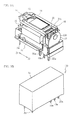
- FIG. 1 is an exploded perspective view illustrating an electromagnetic relay 100.
- FIG. 2A is an exploded perspective view illustrating an electromagnet 32R.
- FIG. 2B is a perspective view illustrating the composition in which a bobbin 16, an armature 24, and the electromagnet 32R are assembled.
- FIG. 3A is a perspective view illustrating the composition in which a card 14, the bobbin 16, the armature 24, the electromagnet 32R and contact members (i.e., a movable contact member 18 and fixed contact members 20 and 22) are assembled.
- FIG. 3B is a perspective view illustrating the electromagnetic relay 100.
- the movable contact member 18 includes terminals 18a, and a movable contact 18b electrically connected to the terminals 18a.
- the fixed contact member 20 includes a terminal 20a, and a fixed contact 20b electrically connected to the terminal 20a.
- Each of the terminals 18a, 20a and 22a is a terminal for performing electric connection between the electromagnetic relay 100 and an external device.
- the contact members are mounted on the housing 12 so as to be located at a side opposite to the end face 28a via the bobbin 16. From a position near the bobbin 16, the fixed contact member 20, the movable contact member 18 and the fixed contact member 22 are arranged in turn.
- the card 14 is disposed on the housing 12, and is coupled with the armature 24.
- the cover 10 is provided so as to cover the housing 12 through the card 14.
- the press force of the caulking punch 40 is unevenly added to the first area 28c. Therefore, as illustrated by an arrow of FIG. 4A , the first area 28c of the iron core 28 curves in the Y-direction. In addition, as illustrated by a lattice hatched of FIG. 4B , distortion 28e (deviation of thickness) occurs in the first area 28c.
- the distortion 28e is roughness of the first area 28c.
- the distortion 28e is easily generated in areas which adjoin the caulking areas 42, for example.
- the magnetic force of the electromagnet 32R varies by the curvature and the distortion 28e. As a result, the beat is not restrained, and the function of the electromagnetic relay 100 is spoiled.
- the caulking punch 40 presses both of the first area 28c and the second area 28d. Thereby, the press force of the caulking punch 40 is hard to be biased, and is almost evenly added to both of the first area 28c and the second area 28d. Therefore, the curvature of the iron core 28 is restrained. Thereby, the beat can be restrained.
- the caulking punch 40 may have a width which straddles the groove 28b and overlaps with the first area 28c and the second area 28d.
- the caulking punch 40 may be shifted from the position of the comparative example, and may be arranged at a position which overlaps with the first area 28c and the second area 28d.
- a part of the first area 28c included in each of the caulking areas 42 may have a size different from a part of the second area 28d included in each of the caulking areas 42.
- the supporting unit 44 contacts the iron core 28 before the caulking punch 40 contacts the iron core 28.
- the supporting unit 44 completely surrounds the end face 28a in the radial direction of the end face 28a. Therefore, the curvature in all directions can be restrained.
- the supporting unit 44 does not need to completely surround the end face 28a, and may surround a part of the end face 28a, for example.
- the shape of the supporting unit 44 may be a shape other than the dome shape, and the supporting unit 44 needs to have an area which contacts the edge of the end face 28a and the side surface of the iron core 28.
- the flattening unit 46 flattens at least a part of an area other than the caulking areas 42 in the end face 28a. Especially, it is desirable that the flattening unit 46 flattens an area which adjoins the caulking areas 42. This is because the distortion 28e is easily generated in the area which adjoins the caulking areas 42. In addition, the flattening unit 46 may flatten the whole area other than the caulking areas 42. Thereby, the flattening of the end face 28a can be improved more.
- FIG. 9B is a cross-section view illustrating another example of the flattening processing and the caulking processing.
- the flattening unit 46 contacts the end face 28a before the caulking punch 40 contacts the end face 28a, and then the flattening processing may be performed in a state where the flattening unit 46 presses the end face 28a. That is, the caulking processing and the flattening processing may be performed at the same time. Thereby, the generation of the distortion can be restrained.
- the first to the third embodiments may be combined with the fourth embodiment. Thereby, the curvature can be restrained and the distortion can be removed. Therefore, the beat can be restrained effectively.
- the projections 16e hold the shading coil 30 in order to fix the shading coil 30 solidly. It is also desirable that the projections 16e hold the shading coil 30 from a plurality of directions.
- the shading coil 30 can be fixed solidly.
- the projections 16e hold the shading coil 30 from a plurality of directions.
- the projections 16e may hold the shading coil 30 from any one of the X-direction and the Y-direction. Alternatively, the projections 16e may hold the shading coil 30 from a direction other than the X-direction and the Y-direction.
- the number of projections 16e is five, the number of projections 16e may be equal to or less than four, or equal to or more than six.
Landscapes
- Physics & Mathematics (AREA)
- Electromagnetism (AREA)
- Engineering & Computer Science (AREA)
- Manufacturing & Machinery (AREA)
- Electromagnets (AREA)
Abstract
Description
- The present invention relates to an electromagnetic relay and a method for manufacturing an electromagnetic relay.
- There is an alternating-current electromagnetic relay which applies an alternating voltage to a coil as an electromagnetic relay that drives a switch with an electromagnet. In order to keep an attractive force of the electromagnet constant and to restrain a beat, a shading coil is attached to an iron core. Since the beat is restrained with the shading coil, the rectification of the alternating voltage is unnecessary.
Patent Document 1 discloses a technique using a permanent magnet and an auxiliary yoke as a member which assists the attractive force. Patent Document 2 discloses a technique which attaches the shading coil to the iron core with a screw mechanism. Patent Document 3 discloses a technique which presses the shading coil toward the iron core and fixes the shading coil. Patent Document 4 discloses a technique which fixes the shading coil by applying caulking processing to a pole face of the iron core. -
- Patent Document 1: Japanese Laid-open Patent Publication No.
2008-171639 - Patent Document 2: Japanese Laid-open Patent Publication No.
6-53027 - Patent Document 3: Japanese Laid-open Patent Publication No.
1-283904 - Patent Document 4: Japanese Unexamined Utility Model Publication No.
62-114411 - By applying caulking processing to the iron core, the restraint effect of the beat of the shading coil is spoiled, and hence there is a possibility that the electromagnetic relay does not operate appropriately. In view of the above described problem, it is an object to provide an electromagnetic relay and a method for manufacturing an electromagnetic relay that can restrain a beat.
- An electromagnetic relay characterized by comprising: an iron core that has an end face and a groove which goes across the end face; and a shading coil that is fitted in the groove; wherein the shading coil is fixed to the iron core by applying caulking processing to the end face.
- With the above-mentioned composition, the caulking processing can be applied to a plurality of areas in the end face which sandwich the groove.
- With the above-mentioned composition, the caulking processing can be applied to the areas at positions which sandwich both ends of the groove.
- With the above-mentioned composition, at least a part of the end face other than an area to which the caulking processing is applied can be flattened.
- With the above-mentioned composition, an area which adjoins the area to which the caulking processing is applied can be flattened.
- An electromagnetic relay of the present invention includes: an iron core that has an end face and a groove which goes across the end face; a shading coil that is fitted in the groove; and a holding unit that is provided in a bobbin into which the iron core is inserted, and holds an outer circumferential surface of the shading coil.
- With the above-mentioned composition, the bobbin can include a storage unit that stores the shading coil, and a plurality of holding units can be projected from an inner wall of the storage unit toward the shading coil.
- A method for manufacturing an electromagnetic relay of the present invention includes: fitting a shading coil in a groove which goes across an end face of an iron core; and fixing the shading coil to the iron core by applying caulking processing to the end face.
- With the above-mentioned composition, the shading coil can be fixed to the iron core by applying caulking processing to a plurality of areas in the end face which sandwich the groove.
- With the above-mentioned composition, the shading coil can be fixed to the iron core by applying caulking processing to the areas at positions which sandwich both ends of the groove.
- With the above-mentioned composition, the method for manufacturing an electromagnetic relay can include flattening the end face.
- With the above-mentioned composition, an area which adjoins an area in the end face to which the caulking processing is applied can be flattened.
- A method for manufacturing an electromagnetic relay of the present invention includes: fitting a shading coil in a groove which goes across an end face of an iron core; and fixing the shading coil to the iron core by applying caulking processing to the end face while supporting the iron core from a radial direction of the end face.
- With the above-mentioned composition, the fixing can be performed while supporting the iron core from a direction intersecting with a direction of the groove which goes across the end face.
- With the above-mentioned composition, the fixing can be performed while supporting the iron core so as to surround the end face.
- According to the present invention, an electromagnetic relay and a method for manufacturing an electromagnetic relay can restrain a beat.
-
-
FIG. 1 is an exploded perspective view illustrating an electromagnetic relay; -
FIG. 2A is an exploded perspective view illustrating an electromagnet; -
FIG. 2B is a perspective view illustrating the composition in which a bobbin, an armature, and the electromagnet are assembled; -
FIG. 3A is a perspective view illustrating the composition in which a card, the bobbin, the armature, the electromagnet and a contact member are assembled; -
FIG. 3B is a perspective view illustrating an electromagnetic relay; -
FIG. 4A is a cross-section view illustrating caulking processing; -
FIG. 4B is a top view illustrating the electromagnet; -
FIG. 5A is a cross-section view illustrating the caulking processing according to a first embodiment; -
FIG. 5B is a top view illustrating the electromagnet; -
FIG. 6A is a cross-section view illustrating the caulking processing according to a second embodiment; -
FIG. 6B is a top view illustrating the electromagnet; -
FIG. 7A is a cross-section view illustrating a caulking punch and a supporting unit; -
FIGs. 7B and 7C are cross-section views illustrating the caulking processing; -
FIG. 8A is a cross-section view illustrating the caulking punch and a flattening unit: -
FIG. 8B is a cross-section view illustrating flattening processing; -
FIG. 8C is a cross-section view illustrating the caulking processing; -
FIG. 9A is a top view illustrating the electromagnet after the flattening processing and the caulking processing; -
FIG. 9B is a cross-section view illustrating another example of the flattening processing and the caulking processing; -
FIG. 10A is a perspective view illustrating the bobbin of the electromagnetic relay according to a fifth embodiment; -
FIG. 10B is a front view illustrating the bobbin; -
FIG. 11A is a perspective view illustrating the electromagnet; and -
FIG. 11B is a front view illustrating the electromagnet. - A description will now be given of the composition of an electromagnetic relay.
FIG. 1 is an exploded perspective view illustrating anelectromagnetic relay 100.FIG. 2A is an exploded perspective view illustrating anelectromagnet 32R.FIG. 2B is a perspective view illustrating the composition in which abobbin 16, anarmature 24, and theelectromagnet 32R are assembled.FIG. 3A is a perspective view illustrating the composition in which acard 14, thebobbin 16, thearmature 24, theelectromagnet 32R and contact members (i.e., amovable contact member 18 and fixedcontact members 20 and 22) are assembled.FIG. 3B is a perspective view illustrating theelectromagnetic relay 100. - As illustrated in
FIG. 1 , theelectromagnetic relay 100 includes acover 10, ahousing 12, thecard 14, thebobbin 16, the contact members, thearmature 24, and theelectromagnet 32R. - As illustrated in
FIGs. 2A and 2B , theelectromagnet 32R includes thebobbin 16, acoil 26 and aniron core 28. Thecoil 26 is wound on anarea 16a of thebobbin 16. Anair hole 16b is formed inside thearea 16a. Theiron core 28 is inserted into theair hole 16b. As described later, anend face 28a of theiron core 28 serves as an attractive surface of theelectromagnet 32R. Agroove 28b going across theend face 28a is provided on theend face 28a. It is assumed that one area in theend face 28a divided by thegroove 28b is afirst area 28c, another area in theend face 28a is asecond area 28d. As illustrated in a dashed line ofFIG. 2A , theiron core 28 penetrates ahole 30a of ashading coil 30. Theshading coil 30 is fitted into thegroove 28b so as to surround thefirst area 28c, for example. The caulking processing is applied to thefirst area 28c, so that theshading coil 30 is fixed to theiron core 28, as described below. A terminal 16c of thebobbin 16 is electrically connected to thecoil 26. Thearmature 24 is provided in opposition to theend face 28a. Thebobbin 16 is inserted into anair hole 12a of thehousing 12. - As illustrated in
FIGs. 1 and3A , themovable contact member 18 includesterminals 18a, and amovable contact 18b electrically connected to theterminals 18a. The fixedcontact member 20 includes a terminal 20a, and afixed contact 20b electrically connected to the terminal 20a. Each of theterminals electromagnetic relay 100 and an external device. As illustrated inFIG. 3A , the contact members are mounted on thehousing 12 so as to be located at a side opposite to theend face 28a via thebobbin 16. From a position near thebobbin 16, the fixedcontact member 20, themovable contact member 18 and the fixedcontact member 22 are arranged in turn. Thecard 14 is disposed on thehousing 12, and is coupled with thearmature 24. As illustrated inFIG. 3B , thecover 10 is provided so as to cover thehousing 12 through thecard 14. - When a voltage is not applied to the
coil 26, theelectromagnet 32R does not generate a magnetic force. Therefore, thearmature 24 is not attracted to theend face 28a, and separates from theend face 28a. Themovable contact member 18 is a member including a plate spring, for example, and causes a force in a Z1 direction to themovable contact 18b. Therefore, themovable contact 18b contacts the fixedcontact 20b, and separates from a fixedcontact 22b. When a voltage is applied to thecoil 26 via the terminal 16c, theelectromagnet 32R generates the magnetic force. Thearmature 24 moves in a Z2 direction, and is attracted to theend face 28a (seeFIG. 2B ). Thearmature 24 presses thecard 14 in the Z2 direction, and thecard 14 presses themovable contact member 18 in the Z2 direction (seeFIG. 3A ). That is, thecard 14 transfers a press force of thearmature 24 to themovable contact member 18. Themovable contact 18b moves in the Z2 direction, separates from the fixedcontact 20b, and contacts the fixedcontact 22b. Thereby, theelectromagnetic relay 100 can be switched. - The curvature and the distortion which occur in the
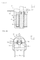
iron core 28 are explained.FIG. 4A is a cross-section view illustrating the caulking processing, andFIG. 4B is a top view illustrating theelectromagnet 32R. Here, a direction in which thegroove 28b goes across theend face 28a is set as an X-direction, and a direction perpendicular to the X-direction in theend face 28a is set as a Y-direction. - As illustrated in
FIG. 4A , acaulking punch 40 disposed on theiron core 28 descends in the Z2 direction. Thecaulking punch 40 presses thefirst area 28c and theshading coil 30 to perform the caulking processing. As illustrated by a dashed square inFIG. 4B ,caulking areas 42 are formed on both ends of thefirst area 28c and theshading coil 30. Each of thecaulking areas 42 is an area where the caulking processing has been performed. In thecaulking areas 42, theend face 28a and theshading coil 30 are crushed. Thus, theshading coil 30 is fixed to theiron core 28. Thecaulking areas 42 are not formed on thesecond area 28d. That is, the caulking processing is not applied to thesecond area 28d. - The press force of the
caulking punch 40 is unevenly added to thefirst area 28c. Therefore, as illustrated by an arrow ofFIG. 4A , thefirst area 28c of theiron core 28 curves in the Y-direction. In addition, as illustrated by a lattice hatched ofFIG. 4B ,distortion 28e (deviation of thickness) occurs in thefirst area 28c. Thedistortion 28e is roughness of thefirst area 28c. Thedistortion 28e is easily generated in areas which adjoin thecaulking areas 42, for example. The magnetic force of theelectromagnet 32R varies by the curvature and thedistortion 28e. As a result, the beat is not restrained, and the function of theelectromagnetic relay 100 is spoiled. Next, a description will be given of embodiments of the present invention with reference to the drawings. - (First Embodiment) A first embodiment indicates an example in which the caulking processing is applied to the
first area 28c and thesecond area 28d. The composition of the electromagnetic relay is the same as that of the above-mentioned electromagnetic relay except for anelectromagnet 32.FIG. 5A is a cross-section view illustrating the caulking processing according to a first embodiment.FIG. 5B is a top view illustrating theelectromagnet 32. - As illustrated in
FIG. 5A , the caulking processing is applied to two areas (i.e., thefirst area 28c and thesecond area 28d) sandwiching thegroove 28b. As a result, thecaulking areas 42 are formed on both of thefirst area 28c and thesecond area 28d, as illustrated inFIG. 5B . Thereby, theshading coil 30 is fixed to theiron core 28. - The
caulking punch 40 presses both of thefirst area 28c and thesecond area 28d. Thereby, the press force of thecaulking punch 40 is hard to be biased, and is almost evenly added to both of thefirst area 28c and thesecond area 28d. Therefore, the curvature of theiron core 28 is restrained. Thereby, the beat can be restrained. - In order to apply the caulking processing to the
first area 28c and thesecond area 28d, thecaulking punch 40 may have a width which straddles thegroove 28b and overlaps with thefirst area 28c and thesecond area 28d. Thecaulking punch 40 may be shifted from the position of the comparative example, and may be arranged at a position which overlaps with thefirst area 28c and thesecond area 28d. For example, a part of thefirst area 28c included in each of thecaulking areas 42 may have a size different from a part of thesecond area 28d included in each of thecaulking areas 42. Moreover, the part of thefirst area 28c included in each of thecaulking areas 42 may have the same size as the part of thesecond area 28d included in each of thecaulking areas 42. Thereby, the press force to be added to thefirst area 28c is substantially equal to the press force to be added to the second area 28d. and hence the curvature is restrained. It is desirable that thecaulking areas 42 are located at both ends 28b-1 of thegroove 28b. That is, it is desirable that the caulking processing is applied to thefirst area 28c and thesecond area 28d in positions which sandwich the both ends 28b-1 of thegroove 28b. Thereby, the press force is added evenly and the curvature is restrained effectively. When a plurality of grooves are provided on theend face 28a and theend face 28a is divided into three or more areas, thecaulking punch 40 may apply the caulking processing to the areas sandwiching the grooves. - (Second Embodiment) A second embodiment indicates an example in which the caulking processing is performed while the
iron core 28 is being supported.FIG. 6A is a cross-section view illustrating the caulking processing according to a second embodiment.FIG. 6B is a top view illustrating theelectromagnet 32. - As illustrated in
FIGs. 6A and 6B , a supportingunit 41 sandwiches theiron core 28 and theshading coil 30 in the Y-direction. The caulking processing is performed in a state where the supportingunit 41 supports the side surfaces of theiron core 28 in the Y-direction. Thereby, the curvature can be restrained. - The supporting
unit 41 may support the side surface of theiron core 28 in a radial direction of theend face 28a (i.e., a direction toward the center of theiron core 28 from the outside of the iron core 28). As illustrated inFIG. 4A , a curvature occurs in the Y-direction easily. Therefore, the supportingunit 41 supports theiron core 28 in the Y-direction, so that the curvature can be restrained effectively. The supportingunit 41 may support the side surface of theiron core 28 in a direction crossing the X-direction other than the Y-direction, and may support the side surface of theiron core 28 so as to surround theend face 28a, for example. The supportingunit 41 is provided on a jig for fixing thebobbin 16, for example. - (Third Embodiment) A third embodiment indicates another example in which the caulking processing is performed while the
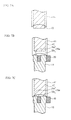
iron core 28 is being supported.FIG. 7A is a cross-section view illustrating thecaulking punch 40 and a supporting unit 44.FIGs. 7B and 7C are cross-section views illustrating the caulking processing. Thebobbin 16 is omitted. Oblique lines are added to thecaulking punch 40. - As illustrated in
FIG. 7A , the supporting unit 44 is provided so as to surround thecaulking punch 40. Thecaulking punch 40 can descend and rise independently of the supporting unit 44. The supporting unit 44 has a shape like a dome which covers theend face 28a, for example. Next, the caulking processing is explained. - As illustrated in
FIG. 7B , the supporting unit 44 descends ahead of thecaulking punch 40, and contacts the edge of theend face 28a. Thereby, the supporting unit 44 supports the edge of theend face 28a in the radial direction of theend face 28a. At this time, thecaulking punch 40 does not contact theend face 28a. As illustrated inFIG. 7C , thecaulking punch 40 performs the caulking processing. That is, the caulking processing is performed in a state where the supporting unit 44 supports the edge of theend face 28a. Therefore, the curvature of theiron core 28 is restrained. - It is desirable that, in order to restrain the curvature effectively, the supporting unit 44 contacts the
iron core 28 before thecaulking punch 40 contacts theiron core 28. The supporting unit 44 completely surrounds theend face 28a in the radial direction of theend face 28a. Therefore, the curvature in all directions can be restrained. Here, the supporting unit 44 does not need to completely surround theend face 28a, and may surround a part of theend face 28a, for example. Especially, it is desirable that the supporting unit 44 supports theend face 28a in the Y-direction. This is because the curvature to be easily generated in the Y-direction can be restrained. The shape of the supporting unit 44 may be a shape other than the dome shape, and the supporting unit 44 needs to have an area which contacts the edge of theend face 28a and the side surface of theiron core 28. - The second and the third embodiments may be combined with the first embodiment. That is, the caulking processing may be applied to both of the
first area 28c and thesecond area 28d while theiron core 28 is being supported in the radial direction of theend face 28a. Thereby, the curvature can be restrained effectively. - (Fourth Embodiment) A fourth embodiment indicates an example in which flattening processing is performed.
FIG. 8A is a cross-section view illustrating thecaulking punch 40 and a flatteningunit 46.FIG. 8B is a cross-section view illustrating the flattening processing.FIG. 8C is a cross-section view illustrating the caulking processing. Thebobbin 16 is omitted. - As illustrated in
FIG. 8A , thecaulking punch 40 is located inside the flatteningunit 46. Thecaulking punch 40 can descend and rise independently of the flatteningunit 46. Next, the caulking processing and the flattening processing are explained. - As illustrated in
FIG. 8B , thecaulking punch 40 descends ahead of the flatteningunit 46, and performs the caulking processing. As illustrated inFIG. 8C , after the caulking processing, the flatteningunit 46 descends and presses theend face 28a. Thereby, the flattening processing is performed, and theend face 28a becomes flat. -
FIG. 9A is a top view illustrating theelectromagnet 32 after the flattening processing and the caulking processing. As illustrated inFIG. 9A , thedistortion 28e (seeFIG. 4B ) is removed by the flattening processing, and aflattening area 28f is formed on theend face 28a. The flatteningarea 28f is flatter than thedistortion 28e. Therefore, the beat can be restrained effectively. - To remove the distortion, the flattening
unit 46 flattens at least a part of an area other than thecaulking areas 42 in theend face 28a. Especially, it is desirable that the flatteningunit 46 flattens an area which adjoins thecaulking areas 42. This is because thedistortion 28e is easily generated in the area which adjoins thecaulking areas 42. In addition, the flatteningunit 46 may flatten the whole area other than thecaulking areas 42. Thereby, the flattening of theend face 28a can be improved more. -
FIG. 9B is a cross-section view illustrating another example of the flattening processing and the caulking processing. As illustrated inFIG. 9B , the flatteningunit 46 contacts theend face 28a before thecaulking punch 40 contacts theend face 28a, and then the flattening processing may be performed in a state where the flatteningunit 46 presses theend face 28a. That is, the caulking processing and the flattening processing may be performed at the same time. Thereby, the generation of the distortion can be restrained. - The first to the third embodiments may be combined with the fourth embodiment. Thereby, the curvature can be restrained and the distortion can be removed. Therefore, the beat can be restrained effectively.
- (Fifth Embodiment) A fifth embodiment indicates that an example in which the
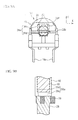
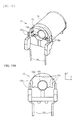
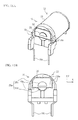
shading coil 30 is fixed to theiron core 28 by pushing an outer circumferential surface of theshading coil 30.FIG. 10A is a perspective view illustrating thebobbin 16 of the electromagnetic relay according to the fifth embodiment.FIG. 10B is a front view illustrating thebobbin 16. Theiron core 28 and theshading coil 30 are not provided on thebobbin 16.FIG. 11A is a perspective view illustrating theelectromagnet 32.FIG. 11B is a front view illustrating theelectromagnet 32. - As illustrated in
FIGs. 10A to 11B , anair hole 16d (i.e., a storage unit) is formed in thebobbin 16. Fiveprojections 16e (i.e., a holding unit) are formed in an inner wall of thebobbin 16 surrounding theair hole 16d. Theprojections 16e are projected to the inside of theair hole 16d from the inner wall. - As illustrated in
FIGs. 11A and 11B , theiron core 28 is inserted into thebobbin 16, and theshading coil 30 is fitted on theiron core 28. Theshading coil 30 is located in theair hole 16d. Theprojections 16e are projected toward theshading coil 30, and hold the outer circumferential surface of theshading coil 30. Thereby, theshading coil 30 is fixed to theiron core 28. According to the fifth embodiment, the caulking processing is not required. Therefore, the curvature and the distortion caused by the caulking processing can be restrained. - It is desirable that the
projections 16e hold theshading coil 30 in order to fix theshading coil 30 solidly. It is also desirable that theprojections 16e hold theshading coil 30 from a plurality of directions. In the fifth embodiment, since theprojections 16e hold theshading coil 30 from the X-direction and the Y-direction, theshading coil 30 can be fixed solidly. Thus, it is desirable that theprojections 16e hold theshading coil 30 from a plurality of directions. Theprojections 16e may hold theshading coil 30 from any one of the X-direction and the Y-direction. Alternatively, theprojections 16e may hold theshading coil 30 from a direction other than the X-direction and the Y-direction. Although the number ofprojections 16e is five, the number ofprojections 16e may be equal to or less than four, or equal to or more than six. - Also in the fifth embodiment, the caulking processing may be performed as with the first to the fourth embodiments, for example. Thereby, the
shading coil 30 is fixed more solidly. - Although the embodiments of the present invention is described in detail, the present invention is not limited to the specifically described embodiments and variations but other embodiments and variations may be made without departing from the scope of the claimed invention.
- 16 bobbin, 16d air hole, 16e projection, 28 iron core, 28a end face, 28b groove, 28c first area, 28d second area, 28e distortion, 28f flattening area, 30 shading coil, 32 electromagnet, 40 caulking punch, 41, 44 supporting unit, 42 caulking area, 46 flattening unit, 100 electromagnetic relay
Claims (15)
- An electromagnetic relay (100) characterized by comprising:an iron core (28) that has an end face (28a) and a groove (28b) which goes across the end face; anda shading coil (30) that is fitted in the groove;wherein the shading coil is fixed to the iron core by applying caulking processing to the end face.
- The electromagnetic relay as claimed in claim 1, characterized in that the caulking processing is applied to a plurality of areas (28c, 28d, 42) in the end face which sandwich the groove.
- The electromagnetic relay as claimed in claim 2, characterized in that the caulking processing is applied to the areas (28c, 28d, 42) at positions which sandwich both ends (28b-1) of the groove (28b).
- The electromagnetic relay as claimed in any one of claims 1 to 3, characterized in that at least a part (28f) of the end face other than an area (42) to which the caulking processing is applied is flattened.
- The electromagnetic relay as claimed in claim 4, characterized in that an area (28f) which adjoins the area (42) to which the caulking processing is applied is flattened.
- The electromagnetic relay as claimed in claim 1, characterized by comprising:a holding unit (16e) that is provided in a bobbin (16) into which the iron core is inserted, and holds an outer circumferential surface of the shading coil.
- The electromagnetic relay as claimed in claim 6, characterized in that the bobbin includes a storage unit (16d) that stores the shading coil, and a plurality of holding units (16e) are projected from an inner wall of the storage unit toward the shading coil.
- A method for manufacturing an electromagnetic relay (100) characterized by comprising:fitting a shading coil (30) in a groove (28b) which goes across an end face (28a) of an iron core (28); andfixing the shading coil to the iron core by applying caulking processing to the end face.
- The method for manufacturing an electromagnetic relay as claimed in claim 8, characterized in that the shading coil is fixed to the iron core by applying caulking processing to a plurality of areas (28c, 28d, 42) in the end face which sandwich the groove.
- The method for manufacturing an electromagnetic relay as claimed in claim 9, characterized in that the shading coil is fixed to the iron core by applying caulking processing to the areas (28c, 28d, 42) at positions which sandwich both ends (28b-1) of the groove (28b).
- The method for manufacturing an electromagnetic relay (100) as claimed in any one of claims 8 to 10, characterized by further comprising:flattening the end face.
- The method for manufacturing an electromagnetic relay (100) as claimed in claim 11, characterized in that an area (28f) which adjoins an area (42) in the end face to which the caulking processing is applied is flattened.
- The method for manufacturing an electromagnetic relay as claimed in claim 8, characterized by further comprising:supporting the iron core (28) from a radial direction of the end face while fixing the shading coil to the iron core.
- The method for manufacturing an electromagnetic relay as claimed in claim 13, characterized in that the fixing is performed while supporting the iron core (28) from a direction intersecting with a direction of the groove (28b) which goes across the end face (28a).
- The method for manufacturing an electromagnetic relay as claimed in claim 13 or 14, characterized in that the fixing is performed while supporting the iron core (28) so as to surround the end face (28a).
Applications Claiming Priority (1)
| Application Number | Priority Date | Filing Date | Title |
|---|---|---|---|
| JP2012261398A JP2014107224A (en) | 2012-11-29 | 2012-11-29 | Electromagnetic relay and method of manufacturing electromagnetic relay |
Publications (2)
| Publication Number | Publication Date |
|---|---|
| EP2738785A1 true EP2738785A1 (en) | 2014-06-04 |
| EP2738785B1 EP2738785B1 (en) | 2016-04-20 |
Family
ID=49546359
Family Applications (1)
| Application Number | Title | Priority Date | Filing Date |
|---|---|---|---|
| EP13192218.9A Not-in-force EP2738785B1 (en) | 2012-11-29 | 2013-11-08 | Electromagnetic relay and method for manufacturing electromagnetic relay |
Country Status (4)
| Country | Link |
|---|---|
| US (2) | US8902029B2 (en) |
| EP (1) | EP2738785B1 (en) |
| JP (1) | JP2014107224A (en) |
| CN (1) | CN104078283A (en) |
Citations (5)
| Publication number | Priority date | Publication date | Assignee | Title |
|---|---|---|---|---|
| US3201660A (en) * | 1963-01-18 | 1965-08-17 | American Mach & Foundry | Electromagnetic relay with shading ring |
| JPS59149009A (en) * | 1983-02-16 | 1984-08-25 | Mitsubishi Electric Corp | Method for fixing shading coil on electromagnetic core |
| DE8804382U1 (en) * | 1988-03-29 | 1989-04-27 | Paul & Siedler Gmbh & Co Kg, 1000 Berlin | Double armature relay |
| EP1478002A2 (en) * | 2003-05-12 | 2004-11-17 | Omron Corporation | Electromagnetic relay |
| WO2006100224A1 (en) * | 2005-03-21 | 2006-09-28 | Siemens Aktiengesellschaft | A short circuit ring securing device for a contactor |
Family Cites Families (7)
| Publication number | Priority date | Publication date | Assignee | Title |
|---|---|---|---|---|
| JPS61207U (en) * | 1984-06-06 | 1986-01-06 | 富士電機株式会社 | electromagnet device |
| JPH0728490B2 (en) | 1985-11-12 | 1995-03-29 | 住友電気工業株式会社 | How to wire an electric wire |
| JPH01283904A (en) | 1988-05-11 | 1989-11-15 | Hitachi Ltd | How to fix the shaded coil of an AC electromagnet |
| US4951018A (en) * | 1989-01-26 | 1990-08-21 | Square D Company | Electromagnetic contactor |
| JPH0653027A (en) * | 1992-07-30 | 1994-02-25 | Omron Corp | Electromagnet device |
| JP4168733B2 (en) * | 2002-11-12 | 2008-10-22 | オムロン株式会社 | Electromagnetic relay |
| JP4855273B2 (en) | 2007-01-10 | 2012-01-18 | オムロン株式会社 | Electromagnet device and electromagnetic relay |
-
2012
- 2012-11-29 JP JP2012261398A patent/JP2014107224A/en active Pending
-
2013
- 2013-10-30 US US14/067,571 patent/US8902029B2/en not_active Expired - Fee Related
- 2013-11-08 EP EP13192218.9A patent/EP2738785B1/en not_active Not-in-force
- 2013-11-28 CN CN201310625006.3A patent/CN104078283A/en active Pending
-
2014
- 2014-08-15 US US14/460,803 patent/US20140352137A1/en not_active Abandoned
Patent Citations (5)
| Publication number | Priority date | Publication date | Assignee | Title |
|---|---|---|---|---|
| US3201660A (en) * | 1963-01-18 | 1965-08-17 | American Mach & Foundry | Electromagnetic relay with shading ring |
| JPS59149009A (en) * | 1983-02-16 | 1984-08-25 | Mitsubishi Electric Corp | Method for fixing shading coil on electromagnetic core |
| DE8804382U1 (en) * | 1988-03-29 | 1989-04-27 | Paul & Siedler Gmbh & Co Kg, 1000 Berlin | Double armature relay |
| EP1478002A2 (en) * | 2003-05-12 | 2004-11-17 | Omron Corporation | Electromagnetic relay |
| WO2006100224A1 (en) * | 2005-03-21 | 2006-09-28 | Siemens Aktiengesellschaft | A short circuit ring securing device for a contactor |
Also Published As
| Publication number | Publication date |
|---|---|
| JP2014107224A (en) | 2014-06-09 |
| EP2738785B1 (en) | 2016-04-20 |
| US20140145802A1 (en) | 2014-05-29 |
| US8902029B2 (en) | 2014-12-02 |
| CN104078283A (en) | 2014-10-01 |
| US20140352137A1 (en) | 2014-12-04 |
Similar Documents
| Publication | Publication Date | Title |
|---|---|---|
| CN102891039B (en) | Relay | |
| CN106057584B (en) | Contact devices and electromagnetic relays | |
| CN109727818A (en) | Electromagnetic relay | |
| CN109727822A (en) | Electromagnetic relay | |
| CN204632680U (en) | Contact Mechanism Department | |
| US20140203898A1 (en) | Electromagnetic relay | |
| EP2919252B1 (en) | Electromagnetic relay | |
| CN105050675A (en) | Electromagnetic relay | |
| CN101826421B (en) | Electromagnetic relay | |
| US9966214B2 (en) | Electromagnetic relay | |
| JP2010113842A (en) | Electromagnetic relay | |
| CN104885183B (en) | The assembled configuration of contact terminal and the electromagnetic relay for possessing it | |
| EP2908327B1 (en) | Electromagnetic relay | |
| JP2008026431A (en) | Lens drive device | |
| CN104428862B (en) | Mobile contact sheet and possess the electromagnetic relay of this mobile contact sheet | |
| US9406469B2 (en) | Electromagnetic relay having a movable contact and a fixed contact and method for manufacturing the same | |
| EP2738785B1 (en) | Electromagnetic relay and method for manufacturing electromagnetic relay | |
| CN203850216U (en) | General high-sensitivity type signal relay | |
| JP5106299B2 (en) | Polarized electromagnetic relay | |
| JP5722850B2 (en) | Electromagnet device and electromagnetic relay | |
| WO2016152444A1 (en) | Coil terminal and electromagnetic relay equipped therewith | |
| CN113168999A (en) | Electromagnetic relay | |
| JP2012160325A (en) | Electromagnetic relay | |
| JP2018098181A (en) | Electromagnetic relay | |
| CN105099100A (en) | Magnetizing device and magnetizing method of rotor core |
Legal Events
| Date | Code | Title | Description |
|---|---|---|---|
| PUAI | Public reference made under article 153(3) epc to a published international application that has entered the european phase |
Free format text: ORIGINAL CODE: 0009012 |
|
| 17P | Request for examination filed |
Effective date: 20131108 |
|
| AK | Designated contracting states |
Kind code of ref document: A1 Designated state(s): AL AT BE BG CH CY CZ DE DK EE ES FI FR GB GR HR HU IE IS IT LI LT LU LV MC MK MT NL NO PL PT RO RS SE SI SK SM TR |
|
| AX | Request for extension of the european patent |
Extension state: BA ME |
|
| R17P | Request for examination filed (corrected) |
Effective date: 20141201 |
|
| RBV | Designated contracting states (corrected) |
Designated state(s): AL AT BE BG CH CY CZ DE DK EE ES FI FR GB GR HR HU IE IS IT LI LT LU LV MC MK MT NL NO PL PT RO RS SE SI SK SM TR |
|
| GRAP | Despatch of communication of intention to grant a patent |
Free format text: ORIGINAL CODE: EPIDOSNIGR1 |
|
| RIC1 | Information provided on ipc code assigned before grant |
Ipc: H01H 50/46 20060101AFI20151015BHEP |
|
| INTG | Intention to grant announced |
Effective date: 20151029 |
|
| RIN1 | Information on inventor provided before grant (corrected) |
Inventor name: KOBAYASHI, KOYURU Inventor name: TAKANO, SATOSHI |
|
| GRAS | Grant fee paid |
Free format text: ORIGINAL CODE: EPIDOSNIGR3 |
|
| RAP1 | Party data changed (applicant data changed or rights of an application transferred) |
Owner name: FUJITSU COMPONENT LIMITED |
|
| RIN1 | Information on inventor provided before grant (corrected) |
Inventor name: TAKANO, SATOSHI Inventor name: KOBAYASHI, KOYURU |
|
| GRAA | (expected) grant |
Free format text: ORIGINAL CODE: 0009210 |
|
| AK | Designated contracting states |
Kind code of ref document: B1 Designated state(s): AL AT BE BG CH CY CZ DE DK EE ES FI FR GB GR HR HU IE IS IT LI LT LU LV MC MK MT NL NO PL PT RO RS SE SI SK SM TR |
|
| REG | Reference to a national code |
Ref country code: GB Ref legal event code: FG4D |
|
| REG | Reference to a national code |
Ref country code: CH Ref legal event code: EP |
|
| REG | Reference to a national code |
Ref country code: AT Ref legal event code: REF Ref document number: 793238 Country of ref document: AT Kind code of ref document: T Effective date: 20160515 |
|
| REG | Reference to a national code |
Ref country code: IE Ref legal event code: FG4D |
|
| REG | Reference to a national code |
Ref country code: DE Ref legal event code: R096 Ref document number: 602013006680 Country of ref document: DE |
|
| REG | Reference to a national code |
Ref country code: LT Ref legal event code: MG4D |
|
| REG | Reference to a national code |
Ref country code: AT Ref legal event code: MK05 Ref document number: 793238 Country of ref document: AT Kind code of ref document: T Effective date: 20160420 |
|
| REG | Reference to a national code |
Ref country code: NL Ref legal event code: MP Effective date: 20160420 |
|
| PG25 | Lapsed in a contracting state [announced via postgrant information from national office to epo] |
Ref country code: FI Free format text: LAPSE BECAUSE OF FAILURE TO SUBMIT A TRANSLATION OF THE DESCRIPTION OR TO PAY THE FEE WITHIN THE PRESCRIBED TIME-LIMIT Effective date: 20160420 Ref country code: PL Free format text: LAPSE BECAUSE OF FAILURE TO SUBMIT A TRANSLATION OF THE DESCRIPTION OR TO PAY THE FEE WITHIN THE PRESCRIBED TIME-LIMIT Effective date: 20160420 Ref country code: LT Free format text: LAPSE BECAUSE OF FAILURE TO SUBMIT A TRANSLATION OF THE DESCRIPTION OR TO PAY THE FEE WITHIN THE PRESCRIBED TIME-LIMIT Effective date: 20160420 Ref country code: NL Free format text: LAPSE BECAUSE OF FAILURE TO SUBMIT A TRANSLATION OF THE DESCRIPTION OR TO PAY THE FEE WITHIN THE PRESCRIBED TIME-LIMIT Effective date: 20160420 Ref country code: NO Free format text: LAPSE BECAUSE OF FAILURE TO SUBMIT A TRANSLATION OF THE DESCRIPTION OR TO PAY THE FEE WITHIN THE PRESCRIBED TIME-LIMIT Effective date: 20160720 |
|
| PG25 | Lapsed in a contracting state [announced via postgrant information from national office to epo] |
Ref country code: HR Free format text: LAPSE BECAUSE OF FAILURE TO SUBMIT A TRANSLATION OF THE DESCRIPTION OR TO PAY THE FEE WITHIN THE PRESCRIBED TIME-LIMIT Effective date: 20160420 Ref country code: ES Free format text: LAPSE BECAUSE OF FAILURE TO SUBMIT A TRANSLATION OF THE DESCRIPTION OR TO PAY THE FEE WITHIN THE PRESCRIBED TIME-LIMIT Effective date: 20160420 Ref country code: RS Free format text: LAPSE BECAUSE OF FAILURE TO SUBMIT A TRANSLATION OF THE DESCRIPTION OR TO PAY THE FEE WITHIN THE PRESCRIBED TIME-LIMIT Effective date: 20160420 Ref country code: GR Free format text: LAPSE BECAUSE OF FAILURE TO SUBMIT A TRANSLATION OF THE DESCRIPTION OR TO PAY THE FEE WITHIN THE PRESCRIBED TIME-LIMIT Effective date: 20160721 Ref country code: LV Free format text: LAPSE BECAUSE OF FAILURE TO SUBMIT A TRANSLATION OF THE DESCRIPTION OR TO PAY THE FEE WITHIN THE PRESCRIBED TIME-LIMIT Effective date: 20160420 Ref country code: SE Free format text: LAPSE BECAUSE OF FAILURE TO SUBMIT A TRANSLATION OF THE DESCRIPTION OR TO PAY THE FEE WITHIN THE PRESCRIBED TIME-LIMIT Effective date: 20160420 Ref country code: AT Free format text: LAPSE BECAUSE OF FAILURE TO SUBMIT A TRANSLATION OF THE DESCRIPTION OR TO PAY THE FEE WITHIN THE PRESCRIBED TIME-LIMIT Effective date: 20160420 Ref country code: PT Free format text: LAPSE BECAUSE OF FAILURE TO SUBMIT A TRANSLATION OF THE DESCRIPTION OR TO PAY THE FEE WITHIN THE PRESCRIBED TIME-LIMIT Effective date: 20160822 |
|
| PG25 | Lapsed in a contracting state [announced via postgrant information from national office to epo] |
Ref country code: BE Free format text: LAPSE BECAUSE OF FAILURE TO SUBMIT A TRANSLATION OF THE DESCRIPTION OR TO PAY THE FEE WITHIN THE PRESCRIBED TIME-LIMIT Effective date: 20160420 |
|
| REG | Reference to a national code |
Ref country code: DE Ref legal event code: R097 Ref document number: 602013006680 Country of ref document: DE |
|
| PG25 | Lapsed in a contracting state [announced via postgrant information from national office to epo] |
Ref country code: RO Free format text: LAPSE BECAUSE OF FAILURE TO SUBMIT A TRANSLATION OF THE DESCRIPTION OR TO PAY THE FEE WITHIN THE PRESCRIBED TIME-LIMIT Effective date: 20160420 Ref country code: CZ Free format text: LAPSE BECAUSE OF FAILURE TO SUBMIT A TRANSLATION OF THE DESCRIPTION OR TO PAY THE FEE WITHIN THE PRESCRIBED TIME-LIMIT Effective date: 20160420 Ref country code: DK Free format text: LAPSE BECAUSE OF FAILURE TO SUBMIT A TRANSLATION OF THE DESCRIPTION OR TO PAY THE FEE WITHIN THE PRESCRIBED TIME-LIMIT Effective date: 20160420 Ref country code: SK Free format text: LAPSE BECAUSE OF FAILURE TO SUBMIT A TRANSLATION OF THE DESCRIPTION OR TO PAY THE FEE WITHIN THE PRESCRIBED TIME-LIMIT Effective date: 20160420 Ref country code: EE Free format text: LAPSE BECAUSE OF FAILURE TO SUBMIT A TRANSLATION OF THE DESCRIPTION OR TO PAY THE FEE WITHIN THE PRESCRIBED TIME-LIMIT Effective date: 20160420 |
|
| PLBE | No opposition filed within time limit |
Free format text: ORIGINAL CODE: 0009261 |
|
| STAA | Information on the status of an ep patent application or granted ep patent |
Free format text: STATUS: NO OPPOSITION FILED WITHIN TIME LIMIT |
|
| PG25 | Lapsed in a contracting state [announced via postgrant information from national office to epo] |
Ref country code: SM Free format text: LAPSE BECAUSE OF FAILURE TO SUBMIT A TRANSLATION OF THE DESCRIPTION OR TO PAY THE FEE WITHIN THE PRESCRIBED TIME-LIMIT Effective date: 20160420 |
|
| PGFP | Annual fee paid to national office [announced via postgrant information from national office to epo] |
Ref country code: IT Payment date: 20161130 Year of fee payment: 4 |
|
| 26N | No opposition filed |
Effective date: 20170123 |
|
| PG25 | Lapsed in a contracting state [announced via postgrant information from national office to epo] |
Ref country code: SI Free format text: LAPSE BECAUSE OF FAILURE TO SUBMIT A TRANSLATION OF THE DESCRIPTION OR TO PAY THE FEE WITHIN THE PRESCRIBED TIME-LIMIT Effective date: 20160420 |
|
| REG | Reference to a national code |
Ref country code: DE Ref legal event code: R119 Ref document number: 602013006680 Country of ref document: DE |
|
| REG | Reference to a national code |
Ref country code: CH Ref legal event code: PL |
|
| PG25 | Lapsed in a contracting state [announced via postgrant information from national office to epo] |
Ref country code: LI Free format text: LAPSE BECAUSE OF NON-PAYMENT OF DUE FEES Effective date: 20161130 Ref country code: CH Free format text: LAPSE BECAUSE OF NON-PAYMENT OF DUE FEES Effective date: 20161130 |
|
| REG | Reference to a national code |
Ref country code: IE Ref legal event code: MM4A |
|
| REG | Reference to a national code |
Ref country code: FR Ref legal event code: ST Effective date: 20170731 |
|
| PG25 | Lapsed in a contracting state [announced via postgrant information from national office to epo] |
Ref country code: LU Free format text: LAPSE BECAUSE OF NON-PAYMENT OF DUE FEES Effective date: 20161130 |
|
| PG25 | Lapsed in a contracting state [announced via postgrant information from national office to epo] |
Ref country code: FR Free format text: LAPSE BECAUSE OF NON-PAYMENT OF DUE FEES Effective date: 20161130 |
|
| PG25 | Lapsed in a contracting state [announced via postgrant information from national office to epo] |
Ref country code: IE Free format text: LAPSE BECAUSE OF NON-PAYMENT OF DUE FEES Effective date: 20161108 Ref country code: DE Free format text: LAPSE BECAUSE OF NON-PAYMENT OF DUE FEES Effective date: 20170601 |
|
| PG25 | Lapsed in a contracting state [announced via postgrant information from national office to epo] |
Ref country code: HU Free format text: LAPSE BECAUSE OF FAILURE TO SUBMIT A TRANSLATION OF THE DESCRIPTION OR TO PAY THE FEE WITHIN THE PRESCRIBED TIME-LIMIT; INVALID AB INITIO Effective date: 20131108 |
|
| PG25 | Lapsed in a contracting state [announced via postgrant information from national office to epo] |
Ref country code: CY Free format text: LAPSE BECAUSE OF FAILURE TO SUBMIT A TRANSLATION OF THE DESCRIPTION OR TO PAY THE FEE WITHIN THE PRESCRIBED TIME-LIMIT Effective date: 20160420 Ref country code: MK Free format text: LAPSE BECAUSE OF FAILURE TO SUBMIT A TRANSLATION OF THE DESCRIPTION OR TO PAY THE FEE WITHIN THE PRESCRIBED TIME-LIMIT Effective date: 20160420 Ref country code: IS Free format text: LAPSE BECAUSE OF FAILURE TO SUBMIT A TRANSLATION OF THE DESCRIPTION OR TO PAY THE FEE WITHIN THE PRESCRIBED TIME-LIMIT Effective date: 20160420 Ref country code: MC Free format text: LAPSE BECAUSE OF FAILURE TO SUBMIT A TRANSLATION OF THE DESCRIPTION OR TO PAY THE FEE WITHIN THE PRESCRIBED TIME-LIMIT Effective date: 20160420 |
|
| GBPC | Gb: european patent ceased through non-payment of renewal fee |
Effective date: 20171108 |
|
| PG25 | Lapsed in a contracting state [announced via postgrant information from national office to epo] |
Ref country code: BG Free format text: LAPSE BECAUSE OF FAILURE TO SUBMIT A TRANSLATION OF THE DESCRIPTION OR TO PAY THE FEE WITHIN THE PRESCRIBED TIME-LIMIT Effective date: 20160420 |
|
| PG25 | Lapsed in a contracting state [announced via postgrant information from national office to epo] |
Ref country code: MT Free format text: LAPSE BECAUSE OF NON-PAYMENT OF DUE FEES Effective date: 20161108 |
|
| PG25 | Lapsed in a contracting state [announced via postgrant information from national office to epo] |
Ref country code: IT Free format text: LAPSE BECAUSE OF NON-PAYMENT OF DUE FEES Effective date: 20171108 Ref country code: AL Free format text: LAPSE BECAUSE OF FAILURE TO SUBMIT A TRANSLATION OF THE DESCRIPTION OR TO PAY THE FEE WITHIN THE PRESCRIBED TIME-LIMIT Effective date: 20160420 Ref country code: TR Free format text: LAPSE BECAUSE OF FAILURE TO SUBMIT A TRANSLATION OF THE DESCRIPTION OR TO PAY THE FEE WITHIN THE PRESCRIBED TIME-LIMIT Effective date: 20160420 |
|
| PG25 | Lapsed in a contracting state [announced via postgrant information from national office to epo] |
Ref country code: GB Free format text: LAPSE BECAUSE OF NON-PAYMENT OF DUE FEES Effective date: 20171108 |