EP2738552A2 - Acoustic methods for sensor communication - Google Patents
Acoustic methods for sensor communication Download PDFInfo
- Publication number
- EP2738552A2 EP2738552A2 EP20130193364 EP13193364A EP2738552A2 EP 2738552 A2 EP2738552 A2 EP 2738552A2 EP 20130193364 EP20130193364 EP 20130193364 EP 13193364 A EP13193364 A EP 13193364A EP 2738552 A2 EP2738552 A2 EP 2738552A2
- Authority
- EP
- European Patent Office
- Prior art keywords
- sensor
- transducer
- signal
- satellite
- base node
- Prior art date
- Legal status (The legal status is an assumption and is not a legal conclusion. Google has not performed a legal analysis and makes no representation as to the accuracy of the status listed.)
- Withdrawn
Links
Images
Classifications
-
- G—PHYSICS
- G01—MEASURING; TESTING
- G01R—MEASURING ELECTRIC VARIABLES; MEASURING MAGNETIC VARIABLES
- G01R29/00—Arrangements for measuring or indicating electric quantities not covered by groups G01R19/00 - G01R27/00
- G01R29/02—Measuring characteristics of individual pulses, e.g. deviation from pulse flatness, rise time or duration
-
- G—PHYSICS
- G01—MEASURING; TESTING
- G01N—INVESTIGATING OR ANALYSING MATERIALS BY DETERMINING THEIR CHEMICAL OR PHYSICAL PROPERTIES
- G01N29/00—Investigating or analysing materials by the use of ultrasonic, sonic or infrasonic waves; Visualisation of the interior of objects by transmitting ultrasonic or sonic waves through the object
- G01N29/04—Analysing solids
- G01N29/043—Analysing solids in the interior, e.g. by shear waves
-
- G—PHYSICS
- G01—MEASURING; TESTING
- G01N—INVESTIGATING OR ANALYSING MATERIALS BY DETERMINING THEIR CHEMICAL OR PHYSICAL PROPERTIES
- G01N29/00—Investigating or analysing materials by the use of ultrasonic, sonic or infrasonic waves; Visualisation of the interior of objects by transmitting ultrasonic or sonic waves through the object
- G01N29/22—Details, e.g. general constructional or apparatus details
- G01N29/24—Probes
- G01N29/2475—Embedded probes, i.e. probes incorporated in objects to be inspected
-
- G—PHYSICS
- G01—MEASURING; TESTING
- G01N—INVESTIGATING OR ANALYSING MATERIALS BY DETERMINING THEIR CHEMICAL OR PHYSICAL PROPERTIES
- G01N29/00—Investigating or analysing materials by the use of ultrasonic, sonic or infrasonic waves; Visualisation of the interior of objects by transmitting ultrasonic or sonic waves through the object
- G01N29/34—Generating the ultrasonic, sonic or infrasonic waves, e.g. electronic circuits specially adapted therefor
- G01N29/348—Generating the ultrasonic, sonic or infrasonic waves, e.g. electronic circuits specially adapted therefor with frequency characteristics, e.g. single frequency signals, chirp signals
-
- G—PHYSICS
- G01—MEASURING; TESTING
- G01R—MEASURING ELECTRIC VARIABLES; MEASURING MAGNETIC VARIABLES
- G01R29/00—Arrangements for measuring or indicating electric quantities not covered by groups G01R19/00 - G01R27/00
-
- H—ELECTRICITY
- H04—ELECTRIC COMMUNICATION TECHNIQUE
- H04B—TRANSMISSION
- H04B11/00—Transmission systems employing ultrasonic, sonic or infrasonic waves
-
- G—PHYSICS
- G01—MEASURING; TESTING
- G01N—INVESTIGATING OR ANALYSING MATERIALS BY DETERMINING THEIR CHEMICAL OR PHYSICAL PROPERTIES
- G01N2291/00—Indexing codes associated with group G01N29/00
- G01N2291/04—Wave modes and trajectories
- G01N2291/048—Transmission, i.e. analysed material between transmitter and receiver
-
- G—PHYSICS
- G01—MEASURING; TESTING
- G01N—INVESTIGATING OR ANALYSING MATERIALS BY DETERMINING THEIR CHEMICAL OR PHYSICAL PROPERTIES
- G01N2291/00—Indexing codes associated with group G01N29/00
- G01N2291/10—Number of transducers
- G01N2291/106—Number of transducers one or more transducer arrays
-
- G—PHYSICS
- G01—MEASURING; TESTING
- G01N—INVESTIGATING OR ANALYSING MATERIALS BY DETERMINING THEIR CHEMICAL OR PHYSICAL PROPERTIES
- G01N2291/00—Indexing codes associated with group G01N29/00
- G01N2291/26—Scanned objects
- G01N2291/269—Various geometry objects
- G01N2291/2693—Rotor or turbine parts
-
- Y—GENERAL TAGGING OF NEW TECHNOLOGICAL DEVELOPMENTS; GENERAL TAGGING OF CROSS-SECTIONAL TECHNOLOGIES SPANNING OVER SEVERAL SECTIONS OF THE IPC; TECHNICAL SUBJECTS COVERED BY FORMER USPC CROSS-REFERENCE ART COLLECTIONS [XRACs] AND DIGESTS
- Y02—TECHNOLOGIES OR APPLICATIONS FOR MITIGATION OR ADAPTATION AGAINST CLIMATE CHANGE
- Y02E—REDUCTION OF GREENHOUSE GAS [GHG] EMISSIONS, RELATED TO ENERGY GENERATION, TRANSMISSION OR DISTRIBUTION
- Y02E10/00—Energy generation through renewable energy sources
- Y02E10/70—Wind energy
- Y02E10/72—Wind turbines with rotation axis in wind direction
Definitions
- the present disclosure relates to methods, systems, and apparatus useful in monitoring and/or controlling various types of equipment.
- Sensors are typically used in connection with performing monitoring, diagnostics, lifing, and control operations of large pieces of equipment such as gas, steam, and wind turbines, generators, and boilers.
- equipment typically resides in harsh, limited access environments.
- a major barrier to the wider deployment of new sensors in such environments is the need to install separate power and signal wire conduits for each sensor individually.
- Signal and power wires are expensive to install in power generation applications, since they must survive for long periods of time in harsh environments, and often must be certified for use in potentially hazardous environments. This increases the cost and therefore the ability to deploy advanced sensing technologies in such environments. Radio frequency based wireless communication solutions are expensive, and not well suited to harsh environments.
- a method may comprise sensing, through a sensor attached to a structure comprising a component of a piece of equipment, a signal being transmitted through the structure, transducing, via a transducer connected to the sensor, the sensor signal into an ultrasonic signal, transmitting the ultrasonic signal through the structure to a base node attached to the structure, transducing the ultrasonic signal at the base node into an electrical signal, relaying the electrical signal through a wired connection of the base node to monitoring or control equipment configured to monitor or control the piece of equipment.
- a system may comprise a plurality of satellite nodes each comprising a sensor connected to a transducer, each transducer configured to transduce a signal received from the respective sensor to which each transducer is connected into an ultrasonic signal, the satellite nodes being associated with a structure comprising a component of a piece of equipment, a base node associated with the structure and spaced from the satellite nodes, the base node configured to receive ultrasonic signals transmitted from the satellite nodes through the structure and transduce the ultrasonic signals into electrical signals, and a wired connection connected to the base node and configured to relay the electrical signals to a controller of the piece of equipment.
- an apparatus may comprise a structure comprising a component of a piece of equipment, the structure capable of transmitting sound therethrough, one or more satellite nodes mounted to the structure, each satellite node configured to receive a signal being transmitted through the structure and transduce the signal into an ultrasonic signal, a base node mounted to the structure, the base node configured to receive the ultrasonic signal transmitted by each satellite node through the structure, transduce the ultrasonic signals into electrical signals, and transmit the electrical signals through a wired connection to a controller of the piece of equipment.
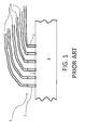
- FIG. 1 illustrates a hard-wired monitoring system of the prior art.
- this system generally 1, includes a number of wired sensors, 2, each of which is attached to a structure, 3, such as the outer shell of a gas turbine, for example, for monitoring turbine blade health.
- each sensor 2 has a power and signal wired conduit 4 that may supply power to its associated sensor 2, and transmit information obtained from the sensor 2 to a monitoring and/or control system (not shown).
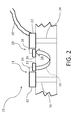
- the system 10 may include a satellite node, generally 11, comprising a satellite sensor 12, and a transmitter or transducer 13, associated with a structure 14.
- the satellite sensor 12 may be a self-powered (energy scavenging) sensor.
- the satellite sensor 12 may be mounted to the structure 14, and may include a satellite sensor probe 16 that may be embedded in the structure 14.
- the transmitter 13 may also be mounted to the structure 14, and may be operatively connected to the satellite sensor 12 via a wired connection 15.
- the satellite sensor may be a passive reluctance or piezoelectric sensor, depending on the application.
- the satellite sensor 12 may be configured to power its associated satellite transducer 13, preprocess and compress sensor data, and transmit data to the satellite transducer 13.
- the structure 14 may comprise a component of a piece of equipment, for example, power generation equipment, such as a component of gas turbines, steam turbines, wind turbines, generators, and boilers that need to be monitored for performance.
- power generation equipment such as a component of gas turbines, steam turbines, wind turbines, generators, and boilers that need to be monitored for performance.
- the structure 14 could be an outer casing for a gas turbine compressor, or the blade of a wind turbine.
- the structure 14 may be of a material, such as metal or ceramic that is capable of transmitting sound, e.g., acoustic signals, such as ultrasonic signals from one point of the structure 14 through the structure 14 to another point of the structure 14, as illustrated by the dotted arrow 18.
- the acoustic signal 18 may be transduced through the structure 14 via the satellite node transducer 13.
- the satellite node transducer 13 may be configured to receive a compressed/processed signal and/or data from the satellite sensor 12 through the connection 15, process and/or compress the sensor signal and/or data, and transduce the satellite sensor signal or data into an ultrasonic signal 18.
- the satellite node transducer 13 may be powered by the satellite sensor 12 to which it is connected, or may be self-powered via energy scavenging.
- the satellite node transducer 13 may comprise active or passive elements, depending on the application.
- the satellite node transducer 13 may further be configured to transmit data, such as compressed data and/or an ultrasonic signal, through the structure 14 to a base node, generally 20, which shall now be described.
- the system 10 may further include a base node, generally 20, spaced a distance from the satellite node 11.
- the base node 20 may also include a base node sensor 22 that may be associated with the structure 14 in a manner similar to the satellite node sensor 12, for example, by being attached thereto or being embedded in the structure 14 with a base sensor probe 24.
- the base node 20 may further include a base node receiver 26 that may be attached to the structure 20 and operatively connected to the base node sensor 22 via a base node connection 28.
- the base node sensor 22 may also be self-powered, for example via energy scavenging, and may power the base node receiver 26.
- the base node receiver 26 may be configured to receive signals from the base node sensor 22, but may also be configured to receive data and/or signals, such as acoustic signals, for example ultrasonic signals 18 from the satellite node transducer 13.
- the base node receiver 26 may be powered by the base node sensor 22, or may be self-powered via energy scavenging.
- the base node receiver 26 may be active or passive, depending on the application.
- the base node receiver 26 may also be configured to aggregate and transmit all the signals and/or data it receives, and transmit those signals and/or data through a single wired connection 30 to a monitor or controller (not shown) that may be configured to monitor and/or control the performance and operation of the piece of equipment of which the structure 14 is a component. It will be understood that a wireless connection may be used in addition to or in lieu of the wired connection 30.
- a plurality of satellite nodes 11 may be attached to or embedded in the structure 14 in order to monitor different regions of the piece of equipment of which the structure 14 is a component.
- Each satellite node may transmit, through its respective satellite node transducer 13, signals and/or data through the structure to the base node receiver 26, where the signals and/or data may be aggregated for transmission by the base node sensor 22 to a monitor or controller (not shown), which may act upon the signals or data received to monitor or control the piece of equipment to which the satellite nodes 11 and base node 20 are attached or embedded.
- the structure 14 to which the satellite nodes 11 and base node 20 are attached or embedded may be a component of a larger piece of equipment, such as a gas turbine, steam turbine, wind turbine, generator, or boiler.
- a gas turbine steam turbine
- wind turbine wind turbine
- generator or boiler.
- Such equipment in operation typically produces noise that could interfere with the acoustic transmissions 18 of the system if such noise is not accounted for.
- One approach to account for such background noise is to transmit the acoustic transmissions 18 at a frequency that is outside the normal spectral range of frequencies of background noise produced by the piece of equipment during normal operation thereof.
- the transmission 18 may be made at a frequency that is higher than the range of background noise.
- the background noise of the equipment might be cancelled using noise cancellation techniques known in the art.
- the satellite sensor 12 may be a reluctance probe
- the structure 14 may be a component of a piece of equipment selected from the group comprising gas turbines and steam turbines
- the signal picked up by the reluctance probe may be a voltage pulse from a turbine blade passage
- the satellite node transducers 13 may be piezoelectric transducers.
- the reluctance probe may be used to detect a voltage pulse generated by a passing blade in a gas turbine to provide a blade tip timing signal that is used to derive the vibratory components of the blade for health monitoring.
- the reluctance probe may also possibly monitor the blade for thermal growth and consequent lessening of clearance between the blade tips and the turbine casing, which can lead to the blade tip contacting the casing, shortening blade life and negatively impacting turbine performance.
- each of the satellite node transducers 13 may be configured to encode their respective transduced ultrasonic frequencies into a frequency unique to that satellite node transducer 13, thereby allowing the base node 20 to identify each satellite node and map discrete information obtained from each satellite sensor 12 to that satellite sensor 12 and therefore to the region of the structure 14 to which that satellite sensor 12 is attached or embedded.
Landscapes
- Physics & Mathematics (AREA)
- General Physics & Mathematics (AREA)
- Chemical & Material Sciences (AREA)
- Immunology (AREA)
- Health & Medical Sciences (AREA)
- Analytical Chemistry (AREA)
- Biochemistry (AREA)
- General Health & Medical Sciences (AREA)
- Pathology (AREA)
- Life Sciences & Earth Sciences (AREA)
- Acoustics & Sound (AREA)
- Engineering & Computer Science (AREA)
- Computer Networks & Wireless Communication (AREA)
- Signal Processing (AREA)
- Wind Motors (AREA)
- Arrangements For Transmission Of Measured Signals (AREA)
- Investigating Or Analyzing Materials By The Use Of Ultrasonic Waves (AREA)
Abstract
A system (10) for monitoring equipment and transmitting data and/or signals from one or more satellite nodes (11) to a base node (20) for transmission to a monitor or controller for the equipment. The system (10) may transmit high frequency acoustic signals from one or more satellite nodes (11) embedded in the equipment through a structural component (14) of the equipment to the base node (20), eliminating the need to hardwire the satellite nodes (11) in harsh environments.
Description
- The present disclosure relates to methods, systems, and apparatus useful in monitoring and/or controlling various types of equipment.
- Sensors are typically used in connection with performing monitoring, diagnostics, lifing, and control operations of large pieces of equipment such as gas, steam, and wind turbines, generators, and boilers. Such equipment typically resides in harsh, limited access environments. A major barrier to the wider deployment of new sensors in such environments is the need to install separate power and signal wire conduits for each sensor individually. Signal and power wires are expensive to install in power generation applications, since they must survive for long periods of time in harsh environments, and often must be certified for use in potentially hazardous environments. This increases the cost and therefore the ability to deploy advanced sensing technologies in such environments. Radio frequency based wireless communication solutions are expensive, and not well suited to harsh environments.
- According to the present invention, there is provided a method that may comprise sensing, through a sensor attached to a structure comprising a component of a piece of equipment, a signal being transmitted through the structure, transducing, via a transducer connected to the sensor, the sensor signal into an ultrasonic signal, transmitting the ultrasonic signal through the structure to a base node attached to the structure, transducing the ultrasonic signal at the base node into an electrical signal, relaying the electrical signal through a wired connection of the base node to monitoring or control equipment configured to monitor or control the piece of equipment.
- According to another aspect of the invention, there is provided a system that may comprise a plurality of satellite nodes each comprising a sensor connected to a transducer, each transducer configured to transduce a signal received from the respective sensor to which each transducer is connected into an ultrasonic signal, the satellite nodes being associated with a structure comprising a component of a piece of equipment, a base node associated with the structure and spaced from the satellite nodes, the base node configured to receive ultrasonic signals transmitted from the satellite nodes through the structure and transduce the ultrasonic signals into electrical signals, and a wired connection connected to the base node and configured to relay the electrical signals to a controller of the piece of equipment.
- According to yet another aspect of the invention, there is provided an apparatus that may comprise a structure comprising a component of a piece of equipment, the structure capable of transmitting sound therethrough, one or more satellite nodes mounted to the structure, each satellite node configured to receive a signal being transmitted through the structure and transduce the signal into an ultrasonic signal, a base node mounted to the structure, the base node configured to receive the ultrasonic signal transmitted by each satellite node through the structure, transduce the ultrasonic signals into electrical signals, and transmit the electrical signals through a wired connection to a controller of the piece of equipment.
- These and other features of the present disclosure will become apparent to one of ordinary skill in the art upon review of the following detailed description when taken in conjunction with the drawings and the appended claims.
-
-
FIG. 1 is an example of a prior art system for monitoring a piece of equipment. -
FIG. 2 is a partial cross sectional view of a signal transmitting and monitoring system of the present disclosure. -
FIG. 1 illustrates a hard-wired monitoring system of the prior art. As illustrated, this system, generally 1, includes a number of wired sensors, 2, each of which is attached to a structure, 3, such as the outer shell of a gas turbine, for example, for monitoring turbine blade health. As illustrated, eachsensor 2, has a power and signal wiredconduit 4 that may supply power to its associatedsensor 2, and transmit information obtained from thesensor 2 to a monitoring and/or control system (not shown). - Referring now to
FIG. 2 , there is illustrated a monitoring/signal transmitting system of the present disclosure, generally 10. Thesystem 10 may include a satellite node, generally 11, comprising asatellite sensor 12, and a transmitter ortransducer 13, associated with astructure 14. Thesatellite sensor 12 may be a self-powered (energy scavenging) sensor. As illustrated, thesatellite sensor 12 may be mounted to thestructure 14, and may include asatellite sensor probe 16 that may be embedded in thestructure 14. Thetransmitter 13 may also be mounted to thestructure 14, and may be operatively connected to thesatellite sensor 12 via awired connection 15. The satellite sensor may be a passive reluctance or piezoelectric sensor, depending on the application. Thesatellite sensor 12 may be configured to power its associatedsatellite transducer 13, preprocess and compress sensor data, and transmit data to thesatellite transducer 13. - The
structure 14 may comprise a component of a piece of equipment, for example, power generation equipment, such as a component of gas turbines, steam turbines, wind turbines, generators, and boilers that need to be monitored for performance. For example, thestructure 14 could be an outer casing for a gas turbine compressor, or the blade of a wind turbine. Thestructure 14 may be of a material, such as metal or ceramic that is capable of transmitting sound, e.g., acoustic signals, such as ultrasonic signals from one point of thestructure 14 through thestructure 14 to another point of thestructure 14, as illustrated by thedotted arrow 18. - As further illustrated, the
acoustic signal 18 may be transduced through thestructure 14 via thesatellite node transducer 13. Thesatellite node transducer 13 may be configured to receive a compressed/processed signal and/or data from thesatellite sensor 12 through theconnection 15, process and/or compress the sensor signal and/or data, and transduce the satellite sensor signal or data into anultrasonic signal 18. Thesatellite node transducer 13 may be powered by thesatellite sensor 12 to which it is connected, or may be self-powered via energy scavenging. Thesatellite node transducer 13 may comprise active or passive elements, depending on the application. Thesatellite node transducer 13 may further be configured to transmit data, such as compressed data and/or an ultrasonic signal, through thestructure 14 to a base node, generally 20, which shall now be described. - As illustrated in
FIG. 2 , thesystem 10 may further include a base node, generally 20, spaced a distance from thesatellite node 11. Thebase node 20 may also include abase node sensor 22 that may be associated with thestructure 14 in a manner similar to thesatellite node sensor 12, for example, by being attached thereto or being embedded in thestructure 14 with abase sensor probe 24. Thebase node 20 may further include abase node receiver 26 that may be attached to thestructure 20 and operatively connected to thebase node sensor 22 via abase node connection 28. Thebase node sensor 22 may also be self-powered, for example via energy scavenging, and may power thebase node receiver 26. - The
base node receiver 26 may be configured to receive signals from thebase node sensor 22, but may also be configured to receive data and/or signals, such as acoustic signals, for exampleultrasonic signals 18 from thesatellite node transducer 13. Thebase node receiver 26 may be powered by thebase node sensor 22, or may be self-powered via energy scavenging. Thebase node receiver 26 may be active or passive, depending on the application. Thebase node receiver 26 may also be configured to aggregate and transmit all the signals and/or data it receives, and transmit those signals and/or data through a single wiredconnection 30 to a monitor or controller (not shown) that may be configured to monitor and/or control the performance and operation of the piece of equipment of which thestructure 14 is a component. It will be understood that a wireless connection may be used in addition to or in lieu of thewired connection 30. - In one embodiment of the disclosure, a plurality of
satellite nodes 11 may be attached to or embedded in thestructure 14 in order to monitor different regions of the piece of equipment of which thestructure 14 is a component. Each satellite node may transmit, through its respectivesatellite node transducer 13, signals and/or data through the structure to thebase node receiver 26, where the signals and/or data may be aggregated for transmission by thebase node sensor 22 to a monitor or controller (not shown), which may act upon the signals or data received to monitor or control the piece of equipment to which thesatellite nodes 11 andbase node 20 are attached or embedded. - As previously discussed, the
structure 14 to which thesatellite nodes 11 andbase node 20 are attached or embedded may be a component of a larger piece of equipment, such as a gas turbine, steam turbine, wind turbine, generator, or boiler. Such equipment in operation typically produces noise that could interfere with theacoustic transmissions 18 of the system if such noise is not accounted for. One approach to account for such background noise is to transmit theacoustic transmissions 18 at a frequency that is outside the normal spectral range of frequencies of background noise produced by the piece of equipment during normal operation thereof. For example, thetransmission 18 may be made at a frequency that is higher than the range of background noise. Alternatively, the background noise of the equipment might be cancelled using noise cancellation techniques known in the art. - In one exemplary system of the present disclosure, the
satellite sensor 12 may be a reluctance probe, thestructure 14 may be a component of a piece of equipment selected from the group comprising gas turbines and steam turbines, the signal picked up by the reluctance probe may be a voltage pulse from a turbine blade passage, and thesatellite node transducers 13 may be piezoelectric transducers. In one such system, the reluctance probe may be used to detect a voltage pulse generated by a passing blade in a gas turbine to provide a blade tip timing signal that is used to derive the vibratory components of the blade for health monitoring. The reluctance probe may also possibly monitor the blade for thermal growth and consequent lessening of clearance between the blade tips and the turbine casing, which can lead to the blade tip contacting the casing, shortening blade life and negatively impacting turbine performance. - In another aspect of the disclosure, each of the
satellite node transducers 13 may be configured to encode their respective transduced ultrasonic frequencies into a frequency unique to thatsatellite node transducer 13, thereby allowing thebase node 20 to identify each satellite node and map discrete information obtained from eachsatellite sensor 12 to thatsatellite sensor 12 and therefore to the region of thestructure 14 to which thatsatellite sensor 12 is attached or embedded. - This written description uses examples to disclose the invention, including the best mode, and also to enable any person of ordinary skill in the art to practice the invention, including making and using any devices or systems and performing any incorporated methods. The steps recited in the accompanying method claims need not be taken in the recited order, where other orders of conducting the steps to achieve the desired result would be readily apparent to those of ordinary skill in the art. The patentable scope of the invention is defined by the claims, and may include other examples that occur to those of ordinary skill in the art. Such other examples are intended to be within the scope of the claims if they have structural elements that do not differ from the literal language of the claims or if they include equivalent structural elements with insubstantial differences from the literal languages of the claims.
Claims (15)
- A method comprising:sensing, through a sensor (12) attached to a structure (14) comprising a component of a piece of power generation equipment, a sensor signal being transmitted through said structure (3);transducing, via a transducer (13) connected to said sensor (12), the sensor signal into an ultrasonic signal (18);transmitting said ultrasonic signal (18) through said structure (14) to a base node (20) attached to said structure (14);transducing said ultrasonic signal (18) at said base node (20) into an electrical signal;relaying the electrical signal through a connection (30) of said base node (20) to monitor or control equipment configured to monitor or control said piece of power generation equipment.
- The method of claim 1, wherein there is a plurality of said transducers (13) and a plurality of said sensors (12), each sensor (12) being connected to one of said plurality of said transducers (13) to form a satellite node (11), and wherein said plurality of said sensors (12) are attached to said structure (14).
- The method of claim 2, wherein said plurality of said sensors (12) are embedded in said structure (14).
- The method of any of claims 1 to 3, wherein said structure (14) is a component of a piece of power generation equipment selected from the group comprising gas turbines, steam turbines, wind turbines, generators, and boilers.
- The method of claim 4, wherein said ultrasonic signal (18) is transmitted at a transmitted frequency outside a normal spectral range of frequencies of background noise produced by said piece of power generation equipment during normal operation thereof.
- The method of claim 5, wherein said transmitted frequency is higher than said normal spectral range of frequencies of background noise.
- The method of any preceding claim, wherein said sensor (12) is a reluctance probe, said structure is a component of a piece of power generation equipment selected from the group comprising gas turbines, steam turbines, and wind turbines, said sensor signal is a voltage pulse from a turbine blade passage sensed by said reluctance probe, and said transducer (13) is a piezoelectric transducer.
- The method of any of claims 2 to 7, wherein each said transducer of said satellite node (11) is configured to encode a transduced ultrasonic frequency into a frequency unique to each said transducer (13), thereby allowing said base node (20) to identify each satellite node (11).
- A system comprising:a plurality of satellite nodes (11) each comprising a sensor (12) connected to a transducer (13), each transducer (13) configured to transduce a signal received from the respective sensor (12) to which each transducer (13) is connected into an ultrasonic signal (18), said plurality of satellite nodes (11) being associated with a structure (14) comprising a component of a piece of power generation equipment;a base node (20) associated with said structure (14) and spaced from said plurality of satellite nodes (11), said base node (20) configured to receive ultrasonic signals (18) transmitted from said plurality of satellite nodes (11) through said structure (14) and transduce said ultrasonic signals (18) into electrical signals; anda connection (30) connected to said base node (20) and configured to relay said electrical signals to a monitor or controller of said piece of power generation equipment.
- The system of claim 9, wherein each said sensor (12) is embedded in said structure (14).
- The system of claim 9 or 10, wherein said ultrasonic signals (18) are transmitted from said plurality of satellite nodes (11) at frequencies that are outside a normal spectral range of frequencies of background noise produced by said piece of power generation equipment during normal operation thereof.
- The system of any of claim 9 to 11, wherein said sensors are self-powered.
- The system of any of claims 9 to 12, wherein each said transducer (13) of each said satellite node (11) is powered by the respective sensor (12) to which each said transducer (13) is connected.
- The system of any of claims 9 to 13, wherein said base node (20) is configured to aggregate the signals received from each said plurality of satellite nodes (11) into aggregated signals and transmit said aggregated signals through said connection to said controller.
- The system of any of claims 9 to 14, wherein each said sensor (12) is configured to preprocess and compress the signal received from the respective sensor (12) into a compressed signal and transmit the compressed signal to the transducer (13) to which each said sensor (12) is connected.
Applications Claiming Priority (1)
| Application Number | Priority Date | Filing Date | Title |
|---|---|---|---|
| US13/687,707 US9146266B2 (en) | 2012-11-28 | 2012-11-28 | Acoustic methods for sensor communication |
Publications (1)
| Publication Number | Publication Date |
|---|---|
| EP2738552A2 true EP2738552A2 (en) | 2014-06-04 |
Family
ID=49641545
Family Applications (1)
| Application Number | Title | Priority Date | Filing Date |
|---|---|---|---|
| EP20130193364 Withdrawn EP2738552A2 (en) | 2012-11-28 | 2013-11-18 | Acoustic methods for sensor communication |
Country Status (3)
| Country | Link |
|---|---|
| US (1) | US9146266B2 (en) |
| EP (1) | EP2738552A2 (en) |
| JP (1) | JP2014122616A (en) |
Families Citing this family (1)
| Publication number | Priority date | Publication date | Assignee | Title |
|---|---|---|---|---|
| US10693567B2 (en) * | 2017-06-29 | 2020-06-23 | The Boeing Company | Vehicle communication system and method |
Family Cites Families (7)
| Publication number | Priority date | Publication date | Assignee | Title |
|---|---|---|---|---|
| US5159580A (en) | 1991-10-03 | 1992-10-27 | Ocean Systems Research, Inc. | Acoustic transducer for sending and receiving acoustic communication signals |
| US5982297A (en) | 1997-10-08 | 1999-11-09 | The Aerospace Corporation | Ultrasonic data communication system |
| US6127942A (en) | 1998-10-27 | 2000-10-03 | The Aerospace Corporation | Ultrasonic power sensory system |
| US6891481B2 (en) * | 2000-10-02 | 2005-05-10 | Baker Hughes Incorporated | Resonant acoustic transmitter apparatus and method for signal transmission |
| US6717418B2 (en) | 2001-11-16 | 2004-04-06 | General Electric Company | Method and apparatus for measuring turbine blade tip clearance |
| US6625084B1 (en) | 2002-08-20 | 2003-09-23 | The United States Of America As Represented By The Secretary Of The Navy | System for acoustically passing electrical signals through a hull |
| US7782709B2 (en) * | 2003-08-22 | 2010-08-24 | Schlumberger Technology Corporation | Multi-physics inversion processing to predict pore pressure ahead of the drill bit |
-
2012
- 2012-11-28 US US13/687,707 patent/US9146266B2/en active Active
-
2013
- 2013-11-18 EP EP20130193364 patent/EP2738552A2/en not_active Withdrawn
- 2013-11-25 JP JP2013242457A patent/JP2014122616A/en active Pending
Non-Patent Citations (1)
| Title |
|---|
| None |
Also Published As
| Publication number | Publication date |
|---|---|
| JP2014122616A (en) | 2014-07-03 |
| US20140144257A1 (en) | 2014-05-29 |
| US9146266B2 (en) | 2015-09-29 |
Similar Documents
| Publication | Publication Date | Title |
|---|---|---|
| EP2412974B1 (en) | System for estimating a condition of a non-conductive hollow structure exposed to a lightning strike | |
| EP1253429A2 (en) | Electromagnetic emission source identification apparatus and associated method, computer device, and computer software program product | |
| CN201464075U (en) | Long-range SAW temperature sensing system | |
| US10618532B2 (en) | Train coupler structural health monitoring system | |
| EP2431273A3 (en) | Wireless sensor for an aircraft propulsion system | |
| US20200277875A1 (en) | Apparatus and Methods for Direct Sensing of Rotational Dynamics of a Rotating Shaft | |
| JP6522454B2 (en) | Sensor information wireless transmitter | |
| CN108332789A (en) | A kind of structural healthy monitoring system of train pantograph | |
| WO2015126738A1 (en) | Self-powered sensing and transmitting device and method of fabricating the same | |
| CN108458858A (en) | A kind of train coupler arranged structural healthy monitoring system | |
| CN102542771A (en) | System and method for transmitting data from a rotating component | |
| JP2013210200A (en) | Ultrasonic thickness measuring device and ultrasonic thickness measuring method | |
| JP6287675B2 (en) | Vibration detection apparatus and vibration detection method | |
| CN106595842A (en) | Generator vibration monitoring system and monitoring method based on external sensor | |
| Tudosa et al. | A flexible DAQ hardware architecture using SoCs for IoT based structural health monitoring systems | |
| US9146266B2 (en) | Acoustic methods for sensor communication | |
| JP2009258063A (en) | Damage monitoring system and measuring device | |
| CN106404214B (en) | Sound wave boiler temperature field measurement device and method based on pseudo-random sequence | |
| JP2020186965A (en) | Ultrasonic sensor system | |
| WO2011007249A1 (en) | Method and system for monitoring a thin structure | |
| KR101180347B1 (en) | a system to reduce vibration-noise of wind turbine | |
| JP6846953B2 (en) | Wing monitoring device and rotating mechanical system | |
| JP2019060747A (en) | Measuring device, monitoring device, and measuring device monitoring system | |
| KR101051006B1 (en) | Self-powered acoustic emission sensor | |
| KR101037295B1 (en) | Self-powered acoustic emission sensor |
Legal Events
| Date | Code | Title | Description |
|---|---|---|---|
| PUAI | Public reference made under article 153(3) epc to a published international application that has entered the european phase |
Free format text: ORIGINAL CODE: 0009012 |
|
| 17P | Request for examination filed |
Effective date: 20131118 |
|
| AK | Designated contracting states |
Kind code of ref document: A2 Designated state(s): AL AT BE BG CH CY CZ DE DK EE ES FI FR GB GR HR HU IE IS IT LI LT LU LV MC MK MT NL NO PL PT RO RS SE SI SK SM TR |
|
| AX | Request for extension of the european patent |
Extension state: BA ME |
|
| STAA | Information on the status of an ep patent application or granted ep patent |
Free format text: STATUS: THE APPLICATION IS DEEMED TO BE WITHDRAWN |
|
| 18D | Application deemed to be withdrawn |
Effective date: 20160601 |