EP2738370A2 - System and method for gas turbine operation - Google Patents
System and method for gas turbine operation Download PDFInfo
- Publication number
- EP2738370A2 EP2738370A2 EP13193677.5A EP13193677A EP2738370A2 EP 2738370 A2 EP2738370 A2 EP 2738370A2 EP 13193677 A EP13193677 A EP 13193677A EP 2738370 A2 EP2738370 A2 EP 2738370A2
- Authority
- EP
- European Patent Office
- Prior art keywords
- gas turbine
- turbine engine
- output value
- base
- target
- Prior art date
- Legal status (The legal status is an assumption and is not a legal conclusion. Google has not performed a legal analysis and makes no representation as to the accuracy of the status listed.)
- Granted
Links
Images

Classifications
-
- F—MECHANICAL ENGINEERING; LIGHTING; HEATING; WEAPONS; BLASTING
- F02—COMBUSTION ENGINES; HOT-GAS OR COMBUSTION-PRODUCT ENGINE PLANTS
- F02C—GAS-TURBINE PLANTS; AIR INTAKES FOR JET-PROPULSION PLANTS; CONTROLLING FUEL SUPPLY IN AIR-BREATHING JET-PROPULSION PLANTS
- F02C9/00—Controlling gas-turbine plants; Controlling fuel supply in air- breathing jet-propulsion plants
-
- F—MECHANICAL ENGINEERING; LIGHTING; HEATING; WEAPONS; BLASTING
- F02—COMBUSTION ENGINES; HOT-GAS OR COMBUSTION-PRODUCT ENGINE PLANTS
- F02C—GAS-TURBINE PLANTS; AIR INTAKES FOR JET-PROPULSION PLANTS; CONTROLLING FUEL SUPPLY IN AIR-BREATHING JET-PROPULSION PLANTS
- F02C9/00—Controlling gas-turbine plants; Controlling fuel supply in air- breathing jet-propulsion plants
- F02C9/16—Control of working fluid flow
- F02C9/20—Control of working fluid flow by throttling; by adjusting vanes
-
- F—MECHANICAL ENGINEERING; LIGHTING; HEATING; WEAPONS; BLASTING
- F02—COMBUSTION ENGINES; HOT-GAS OR COMBUSTION-PRODUCT ENGINE PLANTS
- F02C—GAS-TURBINE PLANTS; AIR INTAKES FOR JET-PROPULSION PLANTS; CONTROLLING FUEL SUPPLY IN AIR-BREATHING JET-PROPULSION PLANTS
- F02C9/00—Controlling gas-turbine plants; Controlling fuel supply in air- breathing jet-propulsion plants
- F02C9/26—Control of fuel supply
- F02C9/28—Regulating systems responsive to plant or ambient parameters, e.g. temperature, pressure, rotor speed
-
- F—MECHANICAL ENGINEERING; LIGHTING; HEATING; WEAPONS; BLASTING
- F02—COMBUSTION ENGINES; HOT-GAS OR COMBUSTION-PRODUCT ENGINE PLANTS
- F02C—GAS-TURBINE PLANTS; AIR INTAKES FOR JET-PROPULSION PLANTS; CONTROLLING FUEL SUPPLY IN AIR-BREATHING JET-PROPULSION PLANTS
- F02C9/00—Controlling gas-turbine plants; Controlling fuel supply in air- breathing jet-propulsion plants
- F02C9/48—Control of fuel supply conjointly with another control of the plant
- F02C9/50—Control of fuel supply conjointly with another control of the plant with control of working fluid flow
- F02C9/54—Control of fuel supply conjointly with another control of the plant with control of working fluid flow by throttling the working fluid, by adjusting vanes
-
- F—MECHANICAL ENGINEERING; LIGHTING; HEATING; WEAPONS; BLASTING
- F05—INDEXING SCHEMES RELATING TO ENGINES OR PUMPS IN VARIOUS SUBCLASSES OF CLASSES F01-F04
- F05D—INDEXING SCHEME FOR ASPECTS RELATING TO NON-POSITIVE-DISPLACEMENT MACHINES OR ENGINES, GAS-TURBINES OR JET-PROPULSION PLANTS
- F05D2270/00—Control
- F05D2270/01—Purpose of the control system
- F05D2270/05—Purpose of the control system to affect the output of the engine
- F05D2270/053—Explicitly mentioned power
-
- F—MECHANICAL ENGINEERING; LIGHTING; HEATING; WEAPONS; BLASTING
- F05—INDEXING SCHEMES RELATING TO ENGINES OR PUMPS IN VARIOUS SUBCLASSES OF CLASSES F01-F04
- F05D—INDEXING SCHEME FOR ASPECTS RELATING TO NON-POSITIVE-DISPLACEMENT MACHINES OR ENGINES, GAS-TURBINES OR JET-PROPULSION PLANTS
- F05D2270/00—Control
- F05D2270/01—Purpose of the control system
- F05D2270/08—Purpose of the control system to produce clean exhaust gases
-
- F—MECHANICAL ENGINEERING; LIGHTING; HEATING; WEAPONS; BLASTING
- F05—INDEXING SCHEMES RELATING TO ENGINES OR PUMPS IN VARIOUS SUBCLASSES OF CLASSES F01-F04
- F05D—INDEXING SCHEME FOR ASPECTS RELATING TO NON-POSITIVE-DISPLACEMENT MACHINES OR ENGINES, GAS-TURBINES OR JET-PROPULSION PLANTS
- F05D2270/00—Control
- F05D2270/01—Purpose of the control system
- F05D2270/11—Purpose of the control system to prolong engine life
-
- F—MECHANICAL ENGINEERING; LIGHTING; HEATING; WEAPONS; BLASTING
- F05—INDEXING SCHEMES RELATING TO ENGINES OR PUMPS IN VARIOUS SUBCLASSES OF CLASSES F01-F04
- F05D—INDEXING SCHEME FOR ASPECTS RELATING TO NON-POSITIVE-DISPLACEMENT MACHINES OR ENGINES, GAS-TURBINES OR JET-PROPULSION PLANTS
- F05D2270/00—Control
- F05D2270/30—Control parameters, e.g. input parameters
- F05D2270/335—Output power or torque
Definitions
- Gas turbine engines generally include a compressor, a combustor, and a turbine.
- the compressor compresses air from an air intake, and subsequently directs the compressed air to the combustor.
- the compressed air received from the compressor is mixed with a fuel and is combusted to create combustion gases.
- the combustion gases are directed into the turbine.
- the combustion gases flow against and around turbine blades of the turbine, thereby driving rotation of the turbine and any external load.
- the external load may include an electrical generator.
- components may degrade and/or foul, resulting in reduced performance over the life of the system.
- the reduced performance may be in the form of reduced gas turbine engine output and/or efficiency and increased operating costs.
- a method in a second embodiment, includes operating a gas turbine engine and determining a base output value based on base load operation of the gas turbine engine under new and clean conditions. The method also includes obtaining a corrective parameter and determining a target output value based at least in part on the base output value and the corrective parameter. Additionally, the method includes monitoring an output value of the gas turbine engine, comparing the output value to the target output value, and adjusting one or more operating conditions of the gas turbine engine such that a difference between the output value and the target output value is less than a threshold value. The difference between the output value and the target output value is caused at least partially by degradation and/or fouling of the gas turbine engine, as compared to new and clean conditions.
- corrective parameters may be obtained (e.g., by the sensors 40) (block 76).
- the corrective parameters may be used with information (e.g., mathematical formula, data, trends, historical data, computer models, knowledge based data, expert data, etc.) and instructions stored in the control system 36 (e.g., in the memory 37) to compensate for tendencies of the gas turbine engine 12 and the effects of the environment on the gas turbine engine 12.
- Such corrective parameters may include a temperature of the ambient air 28 measured with the temperature sensor 44, a pressure of the ambient air 28 measured with the pressure sensor 46, a humidity of the ambient air 28, an inlet temperature of the compressor 26, a pressure loss of the gas turbine engine 12, and/or a pressure loss of the exhaust 22.
- corrective parameters may be considered on cold days when the air is more dense and the mass flow rate through the turbine 20 is naturally increased, thereby decreasing the requirements from the compressor 26 and/or combustor 18.
- the control system 36 may be encoded to compare the output values obtained during operation to the target output value determined from the base output value (e.g., based on new and/or clean operation) (block 82). During operation, when the control system 36 senses that a difference between the output value and the target output value is greater than a threshold value, at least one operating condition of the gas turbine engine 12 may be adjusted such that the output value of the gas turbine engine 12 may be approximately equal to the target output value (block 84). In other words, the operating conditions may be adjusted to increase the output value of the gas turbine engine 12 to be kept relatively constant and approximately equal to the base output value, resulting in increased total output and efficiency of the gas turbine engine 12 over time.
- the adjustable operating conditions may include a firing temperature in the combustor 18, a temperature of the exhaust 22 measured by the temperature sensor 42, a fuel flow rate as controlled by valve 50, fuel composition (e.g., one or more fuels), fuel heating value, oxygen content of oxidant (e.g., air, oxygen enriched air, oxygen reduced air, or pure oxygen), fuel-air ratio, fuel temperature, combustion dynamics, an emissions flow rate, an angle of the IGVs 32 as controlled by the IGV actuator 52, or a combination thereof.
- the control system 36 may provide instructions for increasing the firing temperature in the combustor 18 in order to increase the energy of the combustion gases entering the turbine 20, thereby increasing the power output of the gas turbine engine 12.
- the controller 38 may provide for an increase in the temperature measured at the exhaust 22, which may also generally result from increasing the firing temperature.
- the control system 36 may open the actuated valve 50 to increase the firing temperature by increasing the flow rate of fuel sent to the combustor 18.
- the control system 36 may also increase the amount of oxidant supplied to the combustor 18 (e.g., to increase the total mass flow through the turbine) by using the IGV actuator 52 to open the IGVs 32.
- the operation of the gas turbine engine 12 may be substantially maintained such that the output value (e.g., heat rate and/or power output) approximately matches the target output value.
- Point 142 corresponds to the base firing temperature and base angle of the IGVs 32, indicating the base output value (e.g., gas turbine engine 12 power or efficiency) of the gas turbine engine 12 when it is initially operated in new and/or clean condition.
- Point 144 corresponds to a high firing temperature and a large change in the angle of the IGVs 32, resulting in an increased power output potential for the gas turbine engine 12 in a new and clean state.
- the variables e.g., operating conditions
- additional operating conditions may be adjusted, as previously described.
- Point 174 corresponds to the base firing temperature and base IGV 32 angle, indicating the base output value of the gas turbine engine 12 when it is initially operated in a new and clean state.
- the variables e.g., operating conditions
- the trends in FIG. 4 and FIG. 5 may be considered and applied simultaneously to provide a robust control strategy. Further, additional operating conditions may be adjusted to influence the operation of the gas turbine engine 12.
- output values that may be monitored and maintained may include power output, heat rate, or a combination thereof.
- operating conditions that may be adjusted may include firing temperature in the combustor 18, a temperature of the exhaust 22 measured by the temperature sensor 42, a fuel flow rate as controlled by valve 50, fuel composition (e.g., one or more fuels), fuel heating value, oxygen content of oxidant (e.g., air, oxygen enriched air, oxygen reduced air, or pure oxygen), fuel-air ratio, fuel temperature, combustion dynamics, an emissions flow rate, an angle of the IGVs 32 as controlled by the IGV actuator 52, or a combination thereof.
- the output value of the gas turbine engine 12 may be maintained at approximately the base output value to increase the gas turbine engine 12 output and/or efficiency.
Landscapes
- Engineering & Computer Science (AREA)
- Chemical & Material Sciences (AREA)
- Combustion & Propulsion (AREA)
- Mechanical Engineering (AREA)
- General Engineering & Computer Science (AREA)
- Physics & Mathematics (AREA)
- Fluid Mechanics (AREA)
- Control Of Turbines (AREA)
- Engine Equipment That Uses Special Cycles (AREA)
- Control Of Eletrric Generators (AREA)
Abstract
Description
- The subject matter disclosed herein relates to gas turbine engines, and more specifically, to system and methods for maintaining certain gas turbine operational characteristics over the product life of a gas turbine engine.
- Gas turbine engines generally include a compressor, a combustor, and a turbine. The compressor compresses air from an air intake, and subsequently directs the compressed air to the combustor. In the combustor, the compressed air received from the compressor is mixed with a fuel and is combusted to create combustion gases. The combustion gases are directed into the turbine. In the turbine, the combustion gases flow against and around turbine blades of the turbine, thereby driving rotation of the turbine and any external load. The external load may include an electrical generator. As the gas turbine engine operates, components may degrade and/or foul, resulting in reduced performance over the life of the system. The reduced performance may be in the form of reduced gas turbine engine output and/or efficiency and increased operating costs.
- Certain embodiments commensurate in scope with the originally claimed invention are summarized below. These embodiments are not intended to limit the scope of the claimed invention, but rather these embodiments are intended only to provide a brief summary of possible forms of the invention. Indeed, the invention may encompass a variety of forms that may be similar to or different from the embodiments set forth below.
- In a first embodiment, a system includes a controller configured to control one or more parameters of a gas turbine engine based on a feedback and a predicted lifespan of one or more components of the gas turbine engine to substantially counter the reduction of at least one of power output or efficiency above a threshold level in response to degradation of the gas turbine engine.
- In a second embodiment, a method includes operating a gas turbine engine and determining a base output value based on base load operation of the gas turbine engine under new and clean conditions. The method also includes obtaining a corrective parameter and determining a target output value based at least in part on the base output value and the corrective parameter. Additionally, the method includes monitoring an output value of the gas turbine engine, comparing the output value to the target output value, and adjusting one or more operating conditions of the gas turbine engine such that a difference between the output value and the target output value is less than a threshold value. The difference between the output value and the target output value is caused at least partially by degradation and/or fouling of the gas turbine engine, as compared to new and clean conditions.
- In a third embodiment, a method includes operating a gas turbine engine and determining a base output value based on base load operation of the gas turbine engine. The method also includes determining a predicted lifespan of one or more components of the gas turbine engine at the base load, determining a target lifespan of a first component of the gas turbine engine, and determining a calculated output value based at least in part on the base output value and the target lifespan. Further, the method includes monitoring an output value of the gas turbine engine, comparing the output value to the calculated output value, and adjusting one or more operating conditions of the gas turbine engine, such that a difference between the output value and the calculated output value is less than a threshold value.
- These and other features, aspects, and advantages of the present invention will become better understood when the following detailed description is read with reference to the accompanying drawings, in which like characters represent like parts throughout the drawings, wherein:
-
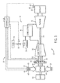
FIG. 1 is a schematic block diagram of an embodiment of a gas turbine system incorporating a system and method to maintain desired gas turbine system operational characteristics over the product life; -
FIG. 2 is a flow diagram of an embodiment of a method for maintaining an output of the gas turbine system ofFIG. 1 ; -
FIG. 3 is a flow diagram of an embodiment of a method for maintaining a product life of a component of the gas turbine system ofFIG. 1 ; -
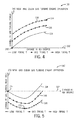
FIG. 4 is a plot showing change in gas turbine power as a function of change in inlet guide vane (IGV) degree and firing temperature; and -
FIG. 5 is a plot showing change in gas turbine heat rate as a function of change in inlet guide vane (IGV) degree and firing temperature. - One or more specific embodiments of the present invention will be described below. In an effort to provide a concise description of these embodiments, all features of an actual implementation may not be described in the specification. It should be appreciated that in the development of any such actual implementation, as in any engineering or design project, numerous implementation-specific decisions must be made to achieve the developers' specific goals, such as compliance with system-related and business-related constraints, which may vary from one implementation to another. Moreover, it should be appreciated that such a development effort might be complex and time consuming, but would nevertheless be a routine undertaking of design, fabrication, and manufacture for those of ordinary skill having the benefit of this disclosure.
- When introducing elements of various embodiments of the present invention, the articles "a," "an," "the," and "said" are intended to mean that there are one or more of the elements. The terms "comprising," "including," and "having" are intended to be inclusive and mean that there may be additional elements other than the listed elements.
- As discussed in detail below, the disclosed embodiments provide systems and methods for maintaining an output value of a gas turbine engine with respect to a product life of a component of the gas turbine engine. In a new and clean state, the gas turbine engine typically produces the most favorable outputs, which may be referred to as a base output values. To preserve gas turbine engine efficiency and cost effectiveness, it may be desirable to maintain operation of the gas turbine engine at, or approximately at, the base output value(s). At least one corrective parameter, generally based on environmental conditions, may be applied to the base output value to determine a target output value for the turbine of the gas turbine engine. The target output value may be maintained throughout the product life of the gas turbine engine by adjusting at least one operating condition of the gas turbine engine.
- For example, output values that may be monitored and maintained may include, but are not limited to, power output, heat rate, or a combination thereof. The power output of the gas turbine engine may be electrical power output created as the shaft rotates and may be measured in Watts. The heat rate of the gas turbine is similar to an efficiency measurement, as it compares the energy value of fuel going into the gas turbine to power output by the gas turbine (e.g., heat rate is equal to the fuel flow rate multiplied by the fuel heating value and divided by the power output of the gas turbine). Further, operating conditions that may be adjusted may include, but are not limited to, firing temperature, exhaust temperature, fuel flow rate, fuel composition (e.g., one or more fuels), fuel heating value, oxygen content of oxidant (e.g., air, oxygen enriched air, oxygen reduced air, or pure oxygen), fuel-air ratio, fuel temperature, combustion dynamics, emissions flow rate, inlet guide vane angle, or a combination thereof. In this manner, the output value of the gas turbine engine may be maintained at approximately the base output target value to increase system efficiency, without negatively affecting the product life or maintenance schedule of the system. However, in alternative embodiments, the operating conditions of the gas turbine engine may be adjusted such that the output value of the gas turbine engine is sufficiently greater or less than the target output value in order to comply with product life or maintenance schedule requirements of the gas turbine engine. For example, if a maintenance shutdown of a gas turbine engine component is scheduled prior to the end of the product life of the turbine, the operating conditions of the gas turbine engine may be adjusted such that the output value exceeds the base output target value with no maintenance impact. In this way, the maximum power output and/or heat rate may be derived from the gas turbine engine prior to the scheduled outage. The gas turbine engine may incorporate a controller and one or more sensors to monitor and adjust output values and operating conditions of the gas turbine engine.
- Turning now to the drawings,
FIG. 1 illustrates a block diagram of an embodiment of agas turbine system 10 having agas turbine engine 12. As discussed below, thesystem 10 includes acontrol system 36 configured to monitor and control aspects of thegas turbine engine 12 to counter degradation and/or reduction in performance, and specifically maintain base load output, heat rate, and various other outputs in response to monitored feedback. Thegas turbine system 10 may use liquid or gaseous fuel, such as natural gas and/or a synthetic gas, to drive thegas turbine system 10. As depicted, one ormore fuel nozzles 14 may intake afuel supply 16. Eachfuel nozzle 14 then mixes the fuel with an oxidant (e.g., air) and may distribute the fuel-air mixture into acombustor 18.Multiple combustors 18 may be arranged circumferentially about thegas turbine engine 12. Further mixing occurs between the fuel and air within thecombustors 18. Although shown schematically as being outside or separate from thecombustors 18, thefuel nozzles 14 may be disposed inside thecombustors 18. The fuel-air mixture combusts in a chamber within thecombustors 18, thereby creating hot, pressurized combustion gases. Thecombustors 18 direct the combustion gases through aturbine 20 and toward anexhaust outlet 22. As the combustion gases pass through theturbine 20, the gases force blades within theturbine 20 to rotate ashaft 24 along a longitudinal axis of thegas turbine system 10. - As illustrated, the
shaft 24 is connected to various components of thegas turbine system 10, including acompressor 26. Thecompressor 26 also includes compressor blades coupled to theshaft 24. As theshaft 24 rotates, the compressor blades within thecompressor 26 also rotate, thereby compressingambient air 28 from anair intake 30. Theair intake 30 may feed theambient air 28 through a series of inlet guide vanes (IGVs) 32, which control the amount ofambient air 28 that is conveyed into thecompressor 26. TheIGVs 32 may be disposed at an angle that can be increased or decreased to allow less or moreambient air 28 into thecompressor 26. Theshaft 24 may also be coupled to aload 34, which may be a vehicle or a stationary load, such as an electrical generator in a power plant or a propeller on an aircraft, for example. Theload 34 may include any suitable device capable of being powered by the rotational output ofturbine system 10. - The
control system 36 may be used to control the operation of thegas turbine engine 12 to increase the operating efficiency of thegas turbine system 10. For example, thecontrol system 36 may be used to monitor and adjust various parameters of thegas turbine engine 12. Particularly, acontroller 38 may include instructions stored on a non-transitory, machine-readable medium (e.g., memory 37) and executable on one or more processors 39. Thecontroller 38 may also communicate withmultiple sensors 40 to monitor aspects of thegas turbine engine 12. In certain embodiments, thecontroller 38 may include anindustrial controller 38, such as a double or triple redundant controller with 2, 3, or more processors 39. For example, the processors 39 may include general-purpose or application-specific microprocessors. In some embodiments, thecontroller 38 may include an application -specific or general purpose computer. Likewise, the memory 37 may include volatile and/or non-volatile memory, random access memory (RAM), read only memory (ROM), flash memory, hard disk drives, removable disk drives and/or removable disks (e.g., CDs, DVDs, BluRay disks, USB pen drives, etc.), or any combination thereof. Regardless of the specific components, instructions stored on the memory 37 may be specifically designed to carry out various monitoring, analysis, and control functions of the disclosed embodiments. In the depicted embodiment, thecontroller 38 may interact with thesensors 40, which include anexhaust temperature sensor 42, an ambientair temperature sensor 44, an ambientair pressure sensor 46, and anIGV angle sensor 48. Further, thecontroller 38 may interact with an actuatedvalve 50 and anIGV actuator 52 to adjust operation of thegas turbine engine 12, as described in detail below. -
FIG. 2 is a flow diagram depicting amethod 70 for maintaining the output of thegas turbine engine 12 throughout the product life of the gas turbine engine 12 (as established by an operator, manufacturer, etc.), thereby improving the efficiency of thegas turbine engine 12. In certain embodiments, themethod 70 may include instructions or code stored on the memory 37 and executable by the processor 39 of thecontroller 38. Thus, each step of themethod 70 may include such instructions or code, and may also employ sensor feedback, mathematical algorithms, computer/mathematical models, historical data and trends, look-up tables, knowledge based data, expert data, market/pricing data, etc. As previously mentioned, thegas turbine engine 12 may produce a maximum output as a new and/or clean unit. However, throughout the product life of thegas turbine engine 12, internal components of thegas turbine engine 12 may degrade, resulting in decreasing output and efficiency. Thus, during initial operation of the gas turbine engine 12 (block 72), a base output value may be determined that corresponds to the output value of the turbine during new and/or clean operation (block 74). For example, the base output value may be the power output and/or heat rate. The base output value may be stored in the control system 36 (e.g., in the memory 37) to be compared to output values obtained as thegas turbine engine 12 degrades/fouls throughout its operation. - To improve the accuracy of the
control system 36, several corrective parameters may be obtained (e.g., by the sensors 40) (block 76). The corrective parameters may be used with information (e.g., mathematical formula, data, trends, historical data, computer models, knowledge based data, expert data, etc.) and instructions stored in the control system 36 (e.g., in the memory 37) to compensate for tendencies of thegas turbine engine 12 and the effects of the environment on thegas turbine engine 12. Such corrective parameters may include a temperature of theambient air 28 measured with thetemperature sensor 44, a pressure of theambient air 28 measured with thepressure sensor 46, a humidity of theambient air 28, an inlet temperature of thecompressor 26, a pressure loss of thegas turbine engine 12, and/or a pressure loss of theexhaust 22. For example, corrective parameters may be considered on cold days when the air is more dense and the mass flow rate through theturbine 20 is naturally increased, thereby decreasing the requirements from thecompressor 26 and/orcombustor 18. - A target output value may be determined based on the base output value and at least one corrective parameter (block 78). Further, the target output value may incorporate the consideration of the product life of the
gas turbine engine 12 as provided by the operator, manufacturer, and so forth. In this way, themethod 70 may be employed to enable thegas turbine engine 12 to generate the target output value throughout its entire operation (i.e., no degradation in performance) without affecting the product life and/or maintenance schedule of thegas turbine engine 12. As thegas turbine engine 12 is in operation, thecontrol system 36 may monitor an output value (e.g., an actual output value) (block 80). The monitored output values may be the power output and/or heat rate in order to be comparable to the base and target output values. Thecontrol system 36 may be encoded to compare the output values obtained during operation to the target output value determined from the base output value (e.g., based on new and/or clean operation) (block 82). During operation, when thecontrol system 36 senses that a difference between the output value and the target output value is greater than a threshold value, at least one operating condition of thegas turbine engine 12 may be adjusted such that the output value of thegas turbine engine 12 may be approximately equal to the target output value (block 84). In other words, the operating conditions may be adjusted to increase the output value of thegas turbine engine 12 to be kept relatively constant and approximately equal to the base output value, resulting in increased total output and efficiency of thegas turbine engine 12 over time. - The adjustable operating conditions may include a firing temperature in the
combustor 18, a temperature of theexhaust 22 measured by thetemperature sensor 42, a fuel flow rate as controlled byvalve 50, fuel composition (e.g., one or more fuels), fuel heating value, oxygen content of oxidant (e.g., air, oxygen enriched air, oxygen reduced air, or pure oxygen), fuel-air ratio, fuel temperature, combustion dynamics, an emissions flow rate, an angle of theIGVs 32 as controlled by theIGV actuator 52, or a combination thereof. For example, when the output value is less than the target output value, thecontrol system 36 may provide instructions for increasing the firing temperature in thecombustor 18 in order to increase the energy of the combustion gases entering theturbine 20, thereby increasing the power output of thegas turbine engine 12. Alternatively, thecontroller 38 may provide for an increase in the temperature measured at theexhaust 22, which may also generally result from increasing the firing temperature. Further, thecontrol system 36 may open the actuatedvalve 50 to increase the firing temperature by increasing the flow rate of fuel sent to thecombustor 18. Thecontrol system 36 may also increase the amount of oxidant supplied to the combustor 18 (e.g., to increase the total mass flow through the turbine) by using theIGV actuator 52 to open the IGVs 32. The operation of thegas turbine engine 12 may be substantially maintained such that the output value (e.g., heat rate and/or power output) approximately matches the target output value. Operating limits (e.g., pressure, temperature, etc.) of thegas turbine engine 12 components may limit the allowable range for the adjustable operating conditions to protect against accelerated component degradation and preserve product life. For example, thecombustor 18 materials may limit the maximum firing temperature. Additionally, theIGVs 32 and the actuatedvalve 50 have fully-open positions that are geometrically and/or physically imposed and cannot be exceeded. Although previously described with respect to increasing the output value of thegas turbine engine 12, the above adjustments may be applied to decrease the output value, such as on a cold day as previously described. -
FIG. 3 is a flow diagram depicting amethod 100 for operating theturbine 20 based on product life of components of thegas turbine engine 12, thereby improving the efficiency and total power generation of thegas turbine engine 12. In certain embodiments, themethod 100 may include instructions or code stored on the memory 37 and executable by the processor 39 of thecontroller 38. Thus, each step of themethod 100 may include such instructions or code, and may also employ sensor feedback, mathematical algorithms, computer/mathematical models, historical data and trends, look-up tables, knowledge based data, expert data, market/pricing data, etc. For example, if a component of thegas turbine engine 12 requires a maintenance outage before the turbine 20 (or any different component of the gas turbine engine 12) requires a maintenance outage, theturbine 20 will have excess product life that may be traded for increased output. Therefore, thegas turbine engine 12 may be operated above the target output value, which shortens the product life of theturbine 20. In this way, a maximum amount of output may be derived from theturbine 20 prior to the scheduled outage of thegas turbine engine 12 by sacrificing the excess product life. Further, in some embodiments, themethod 100 may be utilized by the operator of thegas turbine engine 12 to simply adjust the product life and/or maintenance schedule based on an increased customer demand, such as a power demand, real time pricing of electricity, outages of other power plants, etc. Alternatively, themethod 100 may be employed to extend the product life of thegas turbine engine 12 to postpone an outage. In such an embodiment, thegas turbine engine 12 may be operated below the target output value to enable an extended product life and period of operation. For example, if theturbine 20 is scheduled for an outage a few weeks prior to anentire system 10 outage, thegas turbine engine 12 may be operated below the target output value in order to extend the useable life of theturbine 20 to equal that of thesystem 10. - The
gas turbine engine 12 may be initially operated (block 102) to determine the base output value (block 104). As described previously, the base output value may be based on new and/or clean operation of thegas turbine engine 12 to obtain a maximum output value as the base output value. The base output value may be the power output and/or efficiency of thegas turbine engine 12. Using the base output value, a predicted lifespan (e.g., product life model) of thegas turbine engine 12 may be determined (block 106) based on the product life of a component of thegas turbine engine 12. In general, the manufacturer may provide a recommendation of the predicted lifespan of thegas turbine engine 12 at the base output value. Further, a target lifespan for thegas turbine engine 12 may be determined (block 108). In certain embodiments, the target lifespan may be based on the product life of a component in thegas turbine engine 12. For example, thegas turbine engine 12 may be scheduled for a shutdown due to a maintenance outage of thecompressor 26 that precedes the maintenance date of the other components of thegas turbine engine 12, thus the maintenance outage of thecompressor 26 may dictate the target lifespan of thegas turbine engine 12. - A calculated output value for the
gas turbine engine 12 may be determined (block 110) based at least partially on the target lifespan and the base output value. For example, if the target lifespan of thegas turbine engine 12 is shorter than the predicted lifespan of theturbine 20, the calculated output value may be greater than the base output value in order to maximize the total output supplied by thegas turbine engine 12. In other words, the lifespan of theturbine 20 may be decreased by operating thegas turbine engine 12 above the base output value. Therefore, the excess product life (e.g., predicted lifespan minus target lifespan) of theturbine 20 is exchanged for increased total output. The calculated output value may be the power output and/or efficiency, as it relates to the base output value. As thegas turbine engine 12 operates, an output value actually provided by thegas turbine engine 12 may be monitored (block 112). Thecontrol system 36 may compare the output value (e.g., actual output value) to the calculated output value (block 114). Further, thecontroller 38 may provide instructions to adjust at least one operating condition of thegas turbine engine 12, such that the difference between the output value and the calculated output value is less than a threshold value (block 116). The operating conditions may be adjusted in any combination as described above with respect toFIG. 2 . -
FIG. 4 is aplot 130 depicting change in the power output of thegas turbine engine 12 as a function of change in the degree of theIGVs 32 and firing temperature. Theplot 130 depicts how changes in the angle of theIGVs 32 and the firing temperature within thecombustor 18 may affect the power output of thegas turbine engine 12. Thex-axis 132 represents a first variable (e.g., operating condition), namely change in the angle of theIGVs 32, with the change in angle increasing toward the right end of the x-axis 132 (e.g., theIGVs 32 are more open toward the right). The second variable (e.g., operating condition), namely change in firing temperature, is shown with a series of lines within theplot 130. Theplain line 134 represents a low firing temperature, the dottedline 136 represents a mid firing temperature, and the line marked with x's 138 represents a high firing temperature. The y-axis 140 represents the resultant change ingas turbine engine 12 power output as a factor of the variables. - The
plot 130 exhibits a simple trend for the power output of thegas turbine engine 12 with respect to the variables. For example, as the change in the angle of theIGV 32 increases (e.g., as the IGVs approach the fully-open position), the power output supplied by thegas turbine engine 12 increases. Similarly, as the firing temperature in thecombustor 18 increases, the power output of thegas turbine engine 12 increases. Thus, opening theIGVs 32 and increasing the firing temperature within thecombustor 18 may be effective methods of counteracting degradation of thegas turbine engine 12 over time in an effort to maintain power output. It may be desirable to note certain points on theplot 130. Particularly, points 142 and 144 represent important values with respect to operation of thegas turbine engine 12.Point 142 corresponds to the base firing temperature and base angle of theIGVs 32, indicating the base output value (e.g.,gas turbine engine 12 power or efficiency) of thegas turbine engine 12 when it is initially operated in new and/or clean condition.Point 144 corresponds to a high firing temperature and a large change in the angle of theIGVs 32, resulting in an increased power output potential for thegas turbine engine 12 in a new and clean state. Generally, as thegas turbine engine 12 operates throughout its product life, the variables (e.g., operating conditions) may be adjusted in any combination to utilize this power potential to counteract the power loss due to degradation and/or fouling of thegas turbine engine 12. Further, additional operating conditions may be adjusted, as previously described. -
FIG. 5 is aplot 160 depicting change in the heat rate of thegas turbine engine 12 as a function of change in degree of theIGVs 32 and the firing temperature. Theplot 160 depicts how changes in the angle of theIGVs 32 and the firing temperature within thecombustor 18 may affect the heat rate of thegas turbine engine 12. Thex-axis 162 represents a first variable (e.g., operating condition), namely change in the angle of theIGVs 32, with the change in angle increasing toward the right end of the x-axis 162 (e.g., theIGVs 32 are more open toward the right). The second variable (e.g., operating condition), namely change in firing temperature, is shown with a series of lines within theplot 160. Theplain line 164 represents the base low firing temperature, the dottedline 166 represents a mid firing temperature, and the line marked with x's 168 represents a high firing temperature. The y-axis 170 represents the resultant change in the heat rate of thegas turbine engine 12 as a factor of the variables. - The
plot 160 exhibits a trend for the heat rate of the gas turbine engine 12 (e.g., energy supplied by fuel compared to power output by the gas turbine engine 12) with respect to the variables. For example, as the change in the degree of theIGVs 32 increases, the heat rate of thegas turbine engine 12 may exhibit a U-shape. Thus, opening theIGVs 32 may be an effective method of counteracting degradation of thegas turbine engine 12 until aninflection point 172 of the curve is reached. After theinflection point 172 is reached, opening theIGVs 32 may be detrimental to the heat rate of thegas turbine engine 12. As such, theinflection point 172 may indicate the best achievable heat rate value for thegas turbine engine 12 at a given firing temperature.Point 174 corresponds to the base firing temperature andbase IGV 32 angle, indicating the base output value of thegas turbine engine 12 when it is initially operated in a new and clean state. Generally, as thegas turbine engine 12 operates throughout its product life, the variables (e.g., operating conditions) may be adjusted in any combination to utilize this power potential to counter the power loss due to degradation and/or fouling of thegas turbine engine 12. Further, the trends inFIG. 4 and FIG. 5 may be considered and applied simultaneously to provide a robust control strategy. Further, additional operating conditions may be adjusted to influence the operation of thegas turbine engine 12. - Technical effects of the invention include maintaining an output value of a
gas turbine engine 12 with respect to a product life of the components of thegas turbine engine 12. Thegas turbine engine 12 produces a maximum output and operates at a maximum efficiency when new and/or clean, which is referred to as the base output value. To preserve thegas turbine engine 12 efficiency and cost effectiveness, it may be desirable to maintain operation of thegas turbine engine 12 at this base output value. Corrective parameters, generally based on environmental and/or system conditions, may be applied to the base output value to determine a target output value for thegas turbine engine 12. The target output value of thegas turbine engine 12 may be maintained throughout the product life by adjusting at least one operating condition of thegas turbine engine 12 with the aid of thecontrol system 36. For example, output values that may be monitored and maintained may include power output, heat rate, or a combination thereof. Further, operating conditions that may be adjusted may include firing temperature in thecombustor 18, a temperature of theexhaust 22 measured by thetemperature sensor 42, a fuel flow rate as controlled byvalve 50, fuel composition (e.g., one or more fuels), fuel heating value, oxygen content of oxidant (e.g., air, oxygen enriched air, oxygen reduced air, or pure oxygen), fuel-air ratio, fuel temperature, combustion dynamics, an emissions flow rate, an angle of theIGVs 32 as controlled by theIGV actuator 52, or a combination thereof. In this manner, the output value of thegas turbine engine 12 may be maintained at approximately the base output value to increase thegas turbine engine 12 output and/or efficiency. By limiting the allowable adjustment range, the product life or maintenance schedule of thegas turbine engine 12 may be minimally impacted. However, in alternative embodiments, the operating conditions of thegas turbine engine 12 may be adjusted such that the output value of thegas turbine engine 12 is sufficiently different than the target output value in order to comply with product life or maintenance schedule requirements of a different component in thegas turbine engine 12. For example, if a shutdown is scheduled prior to the end of theturbine 20 product life, the operating conditions of thegas turbine engine 12 may be adjusted such that the output value exceeds the base output value. In this way, maximum power output and/or heat rate may be derived from thegas turbine engine 12 prior to the scheduled outage of thegas turbine engine 12. Thegas turbine system 10 may incorporate acontroller 38 andmultiple sensors 40 to monitor and adjust the output values and operating conditions of thegas turbine system 10. - This written description uses examples to disclose the invention, including the best mode, and also to enable any person skilled in the art to practice the invention, including making and using any devices or systems and performing any incorporated methods. The patentable scope of the invention is defined by the claims, and may include other examples that occur to those skilled in the art. Such other examples are intended to be within the scope of the claims if they have structural elements that do not differ from the literal language of the claims, or if they include equivalent structural elements with insubstantial differences from the literal languages of the claims.
- Various aspects and embodiments of the present invention are defined by the following numbered clauses:
- 1. A system, comprising:
- a controller configured to control one or more parameters of a gas turbine engine based on a feedback and a predicted lifespan of one or more components of the gas turbine engine, wherein the controller comprises instructions disposed on a non-transitory, machine readable medium, wherein the instructions are configured to:
- operate the gas turbine engine;
- determine a base power output, a base heat rate, or a combination thereof based on new and clean operation of the gas turbine engine at base load;
- obtain a corrective parameter;
- determine a target power output, a target heat rate, or a combination thereof based at least in part on the base power output, the base heat rate, or a combination thereof and the corrective parameter;
- monitor a power output, a heat rate, or a combination thereof of the gas turbine engine;
- compare the power output to the target power output, compare the heat rate to the target heat rate, or a combination thereof; and
- adjust the one or more parameters of the gas turbine engine such that a difference between the power output and the target power output, the heat rate and the target heat rate, or a combination thereof is less than a threshold value, wherein the difference between the power output and the target power output, the heat rate and the target heat rate, or the combination thereof is caused at least partially by degradation and/or fouling of the gas turbine engine.
- a controller configured to control one or more parameters of a gas turbine engine based on a feedback and a predicted lifespan of one or more components of the gas turbine engine, wherein the controller comprises instructions disposed on a non-transitory, machine readable medium, wherein the instructions are configured to:
- 2. The system of clause 1, wherein at least one of the power output or heat rate is within approximately 10% of a base output value, wherein the base output value is based on a base output value of the gas turbine engine new and clean.
- 3. The system of any preceding clause, wherein the controller is configured to control operation of a power plant that includes the gas turbine engine.
- 4. The system of any preceding clause, wherein the controller comprises a memory and at least one processor.
- 5. The system of any preceding clause, comprising a sensor configured to generate an input signal to the controller, wherein the input signal is indicative of the parameters of the gas turbine engine.
- 6. The system of any preceding clause, wherein the sensor comprises at least one of an ambient temperature sensor, an ambient pressure sensor, an ambient humidity sensor, a compressor inlet temperature sensor, an inlet pressure sensor, or an exhaust pressure sensor, or a combination thereof.
- 7. The system of any preceding clause, comprising an actuator configured to adjust an operating condition of the gas turbine engine.
- 8. The system of any preceding clause, wherein the actuator comprises at least one of an inlet guide vane actuator, or a fuel flow control valve actuator, or a combination thereof.
- 9. A method, comprising:
- operating a gas turbine engine;
- determining a base output value based on new and clean operation of the gas turbine engine at base load;
- obtaining a corrective parameter;
- determining a target output value based at least in part on the base output value and the corrective parameter;
- monitoring an output value of the gas turbine engine;
- comparing the output value to the target output value; and
- adjusting an operating condition of the gas turbine engine such that a difference between the output value and the target output value is less than a threshold value, wherein the difference between the output value and the target output value is caused at least partially by degradation and/or fouling of the gas turbine engine.
- 10. The method of any preceding clause, wherein the output value comprises at least one of a power output, or a heat rate, or a combination thereof.
- 11. The method of any preceding clause, wherein the base output value corresponds to operation of a new gas turbine engine, or a clean gas turbine engine, or a combination thereof.
- 12. The method of any preceding clause, wherein the corrective parameter comprises at least one of an ambient temperature, an ambient pressure, an ambient humidity, a compressor inlet temperature, an inlet pressure loss, or an exhaust pressure loss, or a combination thereof.
- 13. The method of any preceding clause, wherein the operating condition comprises at least one of a firing temperature, an exhaust temperature, a fuel flow rate, an emissions flow rate, or an inlet guide vane angle, or a combination thereof.
- 14. The method of any preceding clause, comprising maintaining the operating condition less than a maximum operating condition.
- 15. The method of any preceding clause, wherein the maximum operating condition is based at least in part on a predicted lifespan of a component of the gas turbine engine at the base load.
- 16. A method, comprising:
- operating a gas turbine engine;
- determining a base output value based on a base load of the gas turbine engine;
- determining a predicted lifespan of a first component of the gas turbine engine at the base load;
- determining a target lifespan of one or more components of the gas turbine engine;
- determining a calculated output value based at least in part on the base output value and the target lifespan;
- monitoring an output value of the gas turbine engine;
- comparing the output value to the calculated output value; and
- adjusting an operating condition of the gas turbine engine such that a difference between the output value and the calculated output value is less than a threshold value.
- 17. The method of any preceding clause, wherein the target lifespan is based on at least one predicted shutdown of the gas turbine engine.
- 18. The method of any preceding clause, wherein the predicted shutdown of the gas turbine engine is based on a replacement or repair of a second component of the gas turbine engine different from the first component.
- 19. The method of any preceding clause, wherein the target lifespan is less than the predicted lifespan.
- 20. The method of any preceding clause, wherein the calculated output value is greater than the base output value.
- 21. A non-transitory, machine readable medium comprising instructions for performing the method of any preceding clause.
Claims (15)
- A system (10), comprising:a controller (38) configured to control one or more parameters of a gas turbine engine (12) based on a feedback and a predicted lifespan of one or more components of the gas turbine engine (12), wherein the controller (38) comprises instructions disposed on a non-transitory, machine readable medium, wherein the instructions are configured to:operate the gas turbine engine (12);determine a base power output, a base heat rate, or a combination thereof based on new and clean operation of the gas turbine engine (12) at base load;obtain a corrective parameter;determine a target power output, a target heat rate, or a combination thereof based at least in part on the base power output, the base heat rate, or a combination thereof and the corrective parameter;monitor a power output, a heat rate, or a combination thereof of the gas turbine engine (12);compare the power output to the target power output, compare the heat rate to the target heat rate, or a combination thereof; andadjust the one or more parameters of the gas turbine engine (12) such that a difference between the power output and the target power output, the heat rate and the target heat rate, or a combination thereof is less than a threshold value, wherein the difference between the power output and the target power output, the heat rate and the target heat rate, or the combination thereof is caused at least partially by degradation and/or fouling of the gas turbine engine (12).
- The system of claim 1, wherein at least one of the power output or heat rate is within approximately 10% of a base output value, wherein the base output value is based on a base output value of the gas turbine engine (12) new and clean.
- The system of claim 1, 2 or 3, wherein the controller (38) is configured to control operation of a power plant that includes the gas turbine engine (12).
- The system of claim 1, 2 or 3, comprising a sensor (40) configured to generate an input signal to the controller (38), wherein the input signal is indicative of the parameters of the gas turbine engine (12),wherein the sensor (40) preferably comprises at least one of an ambient temperature sensor (44), an ambient pressure sensor (46), an ambient humidity sensor, a compressor inlet temperature sensor, an inlet pressure sensor, or an exhaust pressure sensor, or a combination thereof.
- The system of any preceding claim, comprising an actuator (50, 52) configured to adjust an operating condition of the gas turbine engine (12) wherein the actuator preferably comprises at least one of an inlet guide vane actuator (52), or a fuel flow control valve actuator, or a combination thereof.
- A method (70), comprising:operating (72) a gas turbine engine;determining (74) a base output value based on new and clean operation of the gas turbine engine at base load;obtaining (76) a corrective parameter;determining (78) a target output value based at least in part on the base output value and the corrective parameter;monitoring (80) an output value of the gas turbine engine;comparing (82) the output value to the target output value; andadjusting (84) an operating condition of the gas turbine engine such that a difference between the output value and the target output value is less than a threshold value, wherein the difference between the output value and the target output value is caused at least partially by degradation and/or fouling of the gas turbine engine.
- The method of claim 6, wherein the output value comprises at least one of a power output, or a heat rate, or a combination thereof.
- The method of claim 6 or claim 7, wherein the base output value corresponds to operation of a new gas turbine engine, or a clean gas turbine engine, or a combination thereof.
- The method of claim 6, 7 or 8, wherein the corrective parameter comprises at least one of an ambient temperature, an ambient pressure, an ambient humidity, a compressor inlet temperature, an inlet pressure loss, or an exhaust pressure loss, or a combination thereof.
- The method of any one of claims 6 to 9, wherein the operating condition comprises at least one of a firing temperature, an exhaust temperature, a fuel flow rate, an emissions flow rate, or an inlet guide vane angle, or a combination thereof.
- The method of any one of claims 6 to 10, comprising maintaining the operating condition less than a maximum operating condition, wherein, preferably, the maximum operating condition is based at least in part on a predicted lifespan of a component of the gas turbine engine at the base load.
- A method (100), comprising:operating (102) a gas turbine engine;determining (104) a base output value based on a base load of the gas turbine engine;determining (106) a predicted lifespan of a first component of the gas turbine engine at the base load;determining (108) a target lifespan of one or more components of the gas turbine engine;determining (110) a calculated output value based at least in part on the base output value and the target lifespan;monitoring (112) an output value of the gas turbine engine;comparing (114) the output value to the calculated output value; andadjusting (116) an operating condition of the gas turbine engine such that a difference between the output value and the calculated output value is less than a threshold value.
- The method of claim 12, wherein the target lifespan is based on at least one predicted shutdown of the gas turbine engine, wherein, preferably, the predicted shutdown of the gas turbine engine is based on a replacement or repair of a second component of the gas turbine engine different from the first component.
- The method of claim 12 or claim 13, wherein the target lifespan is less than the predicted lifespan.
- The method of claim 12, 13 or 14, wherein the calculated output value is greater than the base output value.
Applications Claiming Priority (1)
| Application Number | Priority Date | Filing Date | Title |
|---|---|---|---|
| US13/691,389 US9255525B2 (en) | 2012-11-30 | 2012-11-30 | System and method for gas turbine operation |
Publications (3)
| Publication Number | Publication Date |
|---|---|
| EP2738370A2 true EP2738370A2 (en) | 2014-06-04 |
| EP2738370A3 EP2738370A3 (en) | 2017-08-23 |
| EP2738370B1 EP2738370B1 (en) | 2021-11-03 |
Family
ID=49596185
Family Applications (1)
| Application Number | Title | Priority Date | Filing Date |
|---|---|---|---|
| EP13193677.5A Active EP2738370B1 (en) | 2012-11-30 | 2013-11-20 | System and method for gas turbine operation |
Country Status (4)
| Country | Link |
|---|---|
| US (1) | US9255525B2 (en) |
| EP (1) | EP2738370B1 (en) |
| JP (1) | JP6294640B2 (en) |
| CN (1) | CN103850804B (en) |
Cited By (1)
| Publication number | Priority date | Publication date | Assignee | Title |
|---|---|---|---|---|
| EP2921673A1 (en) * | 2014-03-20 | 2015-09-23 | Siemens Aktiengesellschaft | Variable power limit control for gas turbines |
Families Citing this family (54)
| Publication number | Priority date | Publication date | Assignee | Title |
|---|---|---|---|---|
| EP2971699B8 (en) | 2013-03-15 | 2020-01-15 | Rolls-Royce Corporation | Lifing and performance optimization limit management for turbine engine |
| EP2972623A2 (en) * | 2013-03-15 | 2016-01-20 | Rolls-Royce North American Technologies, Inc. | Prognostic health management approaches for propulsion control systems |
| US9476361B2 (en) * | 2013-07-08 | 2016-10-25 | General Electric Company | Systems and methods for control of operating life of a gas turbine |
| JP6217451B2 (en) | 2014-02-26 | 2017-10-25 | 三菱日立パワーシステムズ株式会社 | Fuel control device, combustor, gas turbine, control method and program |
| CN106460568A (en) * | 2014-06-16 | 2017-02-22 | 西门子股份公司 | System and method for supplying energy from intermittent renewable energy sources to an energy grid |
| US9771877B2 (en) * | 2014-11-18 | 2017-09-26 | General Electric Company | Power output and fuel flow based probabilistic control in part load gas turbine tuning, related control systems, computer program products and methods |
| US9803561B2 (en) | 2014-11-18 | 2017-10-31 | General Electric Company | Power output and emissions based degraded gas turbine tuning and control systems, computer program products and related methods |
| US9784183B2 (en) | 2014-11-18 | 2017-10-10 | General Electric Company | Power outlet, emissions, fuel flow and water flow based probabilistic control in liquid-fueled gas turbine tuning, related control systems, computer program products and methods |
| US9771875B2 (en) | 2014-11-18 | 2017-09-26 | General Electric Company | Application of probabilistic control in gas turbine tuning, related control systems, computer program products and methods |
| US9771874B2 (en) | 2014-11-18 | 2017-09-26 | General Electric Company | Power output and fuel flow based probabilistic control in gas turbine tuning, related control systems, computer program products and methods |
| US9771876B2 (en) | 2014-11-18 | 2017-09-26 | General Electric Compnay | Application of probabilistic control in gas turbine tuning with measurement error, related control systems, computer program products and methods |
| US9909507B2 (en) | 2015-01-27 | 2018-03-06 | General Electric Company | Control system for can-to-can variation in combustor system and related method |
| JP6364363B2 (en) * | 2015-02-23 | 2018-07-25 | 三菱日立パワーシステムズ株式会社 | Two-shaft gas turbine and control device and control method thereof |
| US9611791B2 (en) | 2015-04-14 | 2017-04-04 | General Electric Company | Application of probabilistic control in gas turbine tuning for fuel flow-power output parameters, related control systems, computer program products and methods |
| US9599032B2 (en) | 2015-04-14 | 2017-03-21 | General Electric Company | Application of probabilistic control in gas turbine tuning for emissions-fuel flow parameters, related control systems, computer program products and methods |
| US9599029B2 (en) | 2015-04-14 | 2017-03-21 | General Electric Company | Application of probabilistic control in gas turbine tuning for fuel flow-emissions parameters, related control systems, computer program products and methods |
| US9599026B2 (en) | 2015-04-14 | 2017-03-21 | General Electric Company | Application of probabilistic control in gas turbine tuning for exhaust energy-power output parameters, related control systems, computer program products and methods |
| US9599033B2 (en) | 2015-04-14 | 2017-03-21 | General Electric Company | Application of probabilistic control in gas turbine tuning for fuel flow-exhaust energy parameters, related control systems, computer program products and methods |
| US9599025B2 (en) | 2015-04-14 | 2017-03-21 | General Electric Company | Application of probabilistic control in gas turbine tuning for power output-exhaust energy parameters, related control systems, computer program products and methods |
| US9599031B2 (en) | 2015-04-14 | 2017-03-21 | General Electric Company | Application of probabilistic control in gas turbine tuning for power output-emissions parameters, related control systems, computer program products and methods |
| US9599030B2 (en) | 2015-04-14 | 2017-03-21 | General Electric Company | Application of probabilistic control in gas turbine tuning for exhaust energy-fuel flow parameters, related control systems, computer program products and methods |
| US9599024B2 (en) | 2015-04-14 | 2017-03-21 | General Electric Company | Application of probabilistic control in gas turbine tuning for exhaust energy-emissions parameters, related control systems, computer program products and methods |
| US9599027B2 (en) | 2015-04-14 | 2017-03-21 | General Electric Company | Application of probabilistic control in gas turbine tuning for emissions-exhaust energy parameters, related control systems, computer program products and methods |
| US20160313711A1 (en) * | 2015-04-24 | 2016-10-27 | Israel Hernandez Flores | Enhancing base load operation of a power system |
| US9856796B2 (en) | 2015-12-07 | 2018-01-02 | General Electric Company | Application of probabilistic control in gas turbine tuning for power output-emissions parameters with scaling factor, related control systems, computer program products and methods |
| WO2017096613A1 (en) * | 2015-12-11 | 2017-06-15 | General Electric Company | Gas turbine blade flutter monitoring and control system |
| US9879614B2 (en) | 2015-12-16 | 2018-01-30 | General Electric Company | Machine-specific combined probabilistic control in gas turbine tuning for power output-emissions parameters with scaling factor, related control systems, computer program products and methods |
| US9879613B2 (en) | 2015-12-16 | 2018-01-30 | General Electric Company | Application of combined probabilistic control in gas turbine tuning for power output-emissions parameters with scaling factor, related control systems, computer program products and methods |
| US9882454B2 (en) | 2015-12-16 | 2018-01-30 | General Electric Company | Application of combined probabilistic control in gas turbine tuning for power output-emissions parameters with scaling factor, related control systems, computer program products and methods |
| US9879612B2 (en) | 2015-12-16 | 2018-01-30 | General Electric Company | Combined probabilistic control in gas turbine tuning for power output-emissions parameters with scaling factor, related control systems, computer program products and methods |
| US9879615B2 (en) | 2015-12-16 | 2018-01-30 | General Electric Company | Machine-specific probabilistic control in gas turbine tuning for power output-emissions parameters, related control systems, computer program products and methods |
| US9856797B2 (en) | 2015-12-16 | 2018-01-02 | General Electric Company | Application of combined probabilistic control in gas turbine tuning for power output-emissions parameters with scaling factor, related control systems, computer program products and methods |
| US9797315B2 (en) * | 2015-12-16 | 2017-10-24 | General Electric Company | Probabilistic control in gas turbine tuning for power output-emissions parameters, related control systems, computer program products and methods |
| US9790865B2 (en) | 2015-12-16 | 2017-10-17 | General Electric Company | Modelling probabilistic control in gas turbine tuning for power output-emissions parameters, related control systems, computer program products and methods |
| JP6786233B2 (en) * | 2016-03-22 | 2020-11-18 | 三菱パワー株式会社 | Gas turbine characterization device and gas turbine characterization method |
| EP3225812B1 (en) * | 2016-03-29 | 2019-02-27 | Mitsubishi Hitachi Power Systems, Ltd. | A two-shaft gas turbine, and the control method of opening degree of inlet guide vane of the gas turbine |
| US9988928B2 (en) * | 2016-05-17 | 2018-06-05 | Siemens Energy, Inc. | Systems and methods for determining turbomachine engine safe start clearances following a shutdown of the turbomachine engine |
| US10641185B2 (en) * | 2016-12-14 | 2020-05-05 | General Electric Company | System and method for monitoring hot gas path hardware life |
| KR101971337B1 (en) * | 2017-04-24 | 2019-04-22 | 두산중공업 주식회사 | Gas Turbine System and Controlling Method thereof |
| US10762726B2 (en) * | 2017-06-13 | 2020-09-01 | General Electric Company | Hybrid-electric propulsion system for an aircraft |
| US10550717B2 (en) * | 2017-07-26 | 2020-02-04 | General Electric Company | Thermal degradation monitoring system and method for monitoring thermal degradation of equipment |
| JP6963450B2 (en) * | 2017-09-22 | 2021-11-10 | 三菱パワー株式会社 | Rotating machine control device, rotating machine equipment, rotating machine control method, and rotating machine control program |
| GB201721389D0 (en) * | 2017-12-20 | 2018-01-31 | Rolls Royce Plc | Methods, computer programs, non-transitory computer readable storage mediums, signals, and apparatus for controlling electrical power supplied to a component |
| US11268403B2 (en) * | 2018-01-05 | 2022-03-08 | Siemens Energy Global GmbH & Co. KG | Gas turbine engine induction system, corresponding induction heater and method for inductively heating a component |
| KR102036192B1 (en) * | 2018-02-12 | 2019-10-24 | 두산중공업 주식회사 | Turbine drive control apparatus and method according to remaining life |
| JP6934835B2 (en) * | 2018-04-13 | 2021-09-15 | 三菱パワー株式会社 | Gas turbine control device and gas turbine and gas turbine control method |
| CN110886659B (en) * | 2018-09-11 | 2025-01-07 | 普拉特-惠特尼加拿大公司 | Method and system for limiting engine power |
| JP7176932B2 (en) | 2018-11-08 | 2022-11-22 | 三菱重工業株式会社 | Gas turbine control device, gas turbine equipment, gas turbine control method, and gas turbine control program |
| US11667392B2 (en) * | 2019-06-20 | 2023-06-06 | Pratt & Whitney Canada Corp. | Method and system for operating a rotorcraft engine |
| US12158114B2 (en) * | 2021-04-29 | 2024-12-03 | Ge Infrastructure Technology Llc | Dispatch advisor for operating power plant with flexibility |
| US12031490B2 (en) * | 2021-09-20 | 2024-07-09 | Ge Infrastructure Technology Llc | System and method for non-model based control utilizing turbine exit mach number surrogate |
| GB2617309A (en) | 2021-12-21 | 2023-10-11 | Rolls Royce Plc | Aircraft fuel management |
| US20230193834A1 (en) * | 2021-12-21 | 2023-06-22 | Rolls-Royce Plc | Method of controlling an aircraft propulsion system with a variable inlet guide vane, and propulsion system with a variable inlet guide vane scheduling manager |
| US20230212988A1 (en) * | 2022-01-04 | 2023-07-06 | General Electric Company | Versatile control of a propulsion system with a fuel cell |
Family Cites Families (50)
| Publication number | Priority date | Publication date | Assignee | Title |
|---|---|---|---|---|
| US4269030A (en) | 1979-08-06 | 1981-05-26 | Westinghouse Electric Corp. | Power plant optimization control |
| US5347466A (en) | 1991-07-15 | 1994-09-13 | The Board Of Trustees Of The University Of Arkansas | Method and apparatus for power plant simulation and optimization |
| JPH05145966A (en) | 1991-11-18 | 1993-06-11 | Toshiba Corp | Power plant system |
| JP3660757B2 (en) | 1996-08-22 | 2005-06-15 | 株式会社東芝 | Control device for combined cycle power plant |
| JPH10187211A (en) | 1996-12-24 | 1998-07-14 | Hitachi Ltd | Power plant sequence control method |
| JP3646534B2 (en) | 1997-10-17 | 2005-05-11 | 株式会社日立製作所 | Gas turbine power plant |
| US6463380B1 (en) * | 1999-06-01 | 2002-10-08 | General Electric Company | Control system and method for controlling an engine in response to deterioration of the engine |
| US6226974B1 (en) * | 1999-06-25 | 2001-05-08 | General Electric Co. | Method of operation of industrial gas turbine for optimal performance |
| US6364602B1 (en) * | 2000-01-06 | 2002-04-02 | General Electric Company | Method of air-flow measurement and active operating limit line management for compressor surge avoidance |
| JP4513936B2 (en) * | 2000-06-20 | 2010-07-28 | 株式会社Ihi | Fuel flow control method for gas turbine |
| JP3799217B2 (en) | 2000-06-22 | 2006-07-19 | 株式会社日立製作所 | Power generation facility operation management system and maintenance management service method |
| GB0029760D0 (en) * | 2000-12-06 | 2001-01-17 | Secr Defence Brit | Tracking systems for detecting sensor errors |
| GB2374904A (en) * | 2001-04-26 | 2002-10-30 | Bowman Power Systems Ltd | Controlling temperature in gas turbine apparatus during startup or shutdown |
| JP2003013744A (en) * | 2001-06-29 | 2003-01-15 | Ebara Corp | Gas turbine controller, cogeneration system |
| US6625987B2 (en) * | 2001-07-31 | 2003-09-30 | General Electric Co. | Control strategy for gas turbine engine |
| WO2003044353A1 (en) * | 2001-11-15 | 2003-05-30 | Goodrich Pump & Engine Control Systems, Inc. | Method and apparatus for adaptive acceleration schedules in gas turbine engine control systems |
| DE60120192T2 (en) | 2001-11-29 | 2006-11-16 | Abb Research Ltd. | Optimum operation of a power plant |
| US6823675B2 (en) * | 2002-11-13 | 2004-11-30 | General Electric Company | Adaptive model-based control systems and methods for controlling a gas turbine |
| US20040102872A1 (en) * | 2002-11-26 | 2004-05-27 | Schick Louis Andrew | Method and tool for power plant operational optimization |
| US6823253B2 (en) * | 2002-11-27 | 2004-11-23 | General Electric Company | Methods and apparatus for model predictive control of aircraft gas turbine engines |
| US7043348B2 (en) * | 2003-03-03 | 2006-05-09 | Honeywell International, Inc. | Transient fault detection system and method |
| US7194382B2 (en) * | 2004-02-06 | 2007-03-20 | Georgia Tech Research Corporation | Systems and methods for detection of combustor stability margin |
| US7062370B2 (en) * | 2004-03-30 | 2006-06-13 | Honeywell International Inc. | Model-based detection, diagnosis of turbine engine faults |
| US7216489B2 (en) * | 2004-05-26 | 2007-05-15 | Honeywell International, Inc. | System and method for lightoff detection in turbine engines |
| US7243042B2 (en) * | 2004-11-30 | 2007-07-10 | Siemens Power Generation, Inc. | Engine component life monitoring system and method for determining remaining useful component life |
| US7693643B2 (en) * | 2005-02-14 | 2010-04-06 | Honeywell International Inc. | Fault detection system and method for turbine engine fuel systems |
| DE602005008706D1 (en) * | 2005-03-24 | 2008-09-18 | Abb Research Ltd | Estimate the state parameters or appearance of an aging system |
| JP2006291762A (en) * | 2005-04-07 | 2006-10-26 | Honda Motor Co Ltd | Operation control device for gas turbine engine |
| US7222048B2 (en) * | 2005-04-21 | 2007-05-22 | General Electric Company | Methods and systems for diagnosing machinery |
| EP1768007A1 (en) * | 2005-09-22 | 2007-03-28 | Abb Research Ltd. | Monitoring a system having degrading components |
| US7603222B2 (en) * | 2005-11-18 | 2009-10-13 | General Electric Company | Sensor diagnostics using embedded model quality parameters |
| US7565805B2 (en) * | 2005-11-22 | 2009-07-28 | General Electric Company | Method for operating gas turbine engine systems |
| US7784261B2 (en) | 2006-05-25 | 2010-08-31 | Siemens Energy, Inc. | Combined cycle power plant |
| US7395188B1 (en) * | 2006-12-07 | 2008-07-01 | General Electric Company | System and method for equipment life estimation |
| DE502008000599D1 (en) | 2007-02-14 | 2010-06-10 | Alstom Technology Ltd | METHOD FOR OPERATING A POWER PLANT |
| CA2679632C (en) | 2007-03-12 | 2018-01-09 | Emerson Process Management Power & Water Solutions, Inc. | Method and apparatus for generalized performance evaluation of equipment using achievable performance derived from statistics and real-time data |
| US8116990B2 (en) * | 2007-10-19 | 2012-02-14 | Ashok Koul | Method and system for real-time prognosis analysis and usage based residual life assessment of turbine engine components and display |
| ES2457819T3 (en) | 2007-12-10 | 2014-04-29 | Alstom Technology Ltd | Procedure for the regulation of a gas turbine in a power plant |
| US8165826B2 (en) * | 2008-09-30 | 2012-04-24 | The Boeing Company | Data driven method and system for predicting operational states of mechanical systems |
| US20100089067A1 (en) * | 2008-10-10 | 2010-04-15 | General Electric Company | Adaptive performance model and methods for system maintenance |
| US7941281B2 (en) * | 2008-12-22 | 2011-05-10 | General Electric Company | System and method for rotor blade health monitoring |
| FR2939170B1 (en) * | 2008-11-28 | 2010-12-31 | Snecma | DETECTION OF ANOMALY IN AN AIRCRAFT ENGINE. |
| JP5276543B2 (en) * | 2009-07-29 | 2013-08-28 | 三菱重工業株式会社 | Gas turbine operating method and gas turbine |
| JP2011048688A (en) | 2009-08-27 | 2011-03-10 | Hitachi Ltd | Plant life cycle evaluation device and method |
| JP2011102548A (en) * | 2009-11-10 | 2011-05-26 | Toyota Motor Corp | Gas turbine control device |
| RU2523191C2 (en) | 2009-12-31 | 2014-07-20 | Абб Рисерч Лтд | Method and control system for power plant load planning |
| US20110210555A1 (en) * | 2010-02-26 | 2011-09-01 | Xia Jian Y | Gas turbine driven electric power system with constant output through a full range of ambient conditions |
| US8862433B2 (en) * | 2010-05-18 | 2014-10-14 | United Technologies Corporation | Partitioning of turbomachine faults |
| US9342060B2 (en) * | 2010-09-14 | 2016-05-17 | United Technologies Corporation | Adaptive control for a gas turbine engine |
| US20130024179A1 (en) * | 2011-07-22 | 2013-01-24 | General Electric Company | Model-based approach for personalized equipment degradation forecasting |
-
2012
- 2012-11-30 US US13/691,389 patent/US9255525B2/en active Active
-
2013
- 2013-11-20 EP EP13193677.5A patent/EP2738370B1/en active Active
- 2013-11-27 JP JP2013244511A patent/JP6294640B2/en active Active
- 2013-11-29 CN CN201310628852.0A patent/CN103850804B/en active Active
Non-Patent Citations (1)
| Title |
|---|
| None |
Cited By (3)
| Publication number | Priority date | Publication date | Assignee | Title |
|---|---|---|---|---|
| EP2921673A1 (en) * | 2014-03-20 | 2015-09-23 | Siemens Aktiengesellschaft | Variable power limit control for gas turbines |
| WO2015139949A1 (en) * | 2014-03-20 | 2015-09-24 | Siemens Aktiengesellschaft | Variable limit-value power control for gas turbines |
| US10077718B2 (en) | 2014-03-20 | 2018-09-18 | Siemens Aktiengesellschaft | Variable power limit control for gas turbines |
Also Published As
| Publication number | Publication date |
|---|---|
| US20140156165A1 (en) | 2014-06-05 |
| EP2738370A3 (en) | 2017-08-23 |
| EP2738370B1 (en) | 2021-11-03 |
| JP6294640B2 (en) | 2018-03-14 |
| CN103850804A (en) | 2014-06-11 |
| JP2014111937A (en) | 2014-06-19 |
| US9255525B2 (en) | 2016-02-09 |
| CN103850804B (en) | 2017-01-04 |
Similar Documents
| Publication | Publication Date | Title |
|---|---|---|
| US9255525B2 (en) | System and method for gas turbine operation | |
| US7549292B2 (en) | Method of controlling bypass air split to gas turbine combustor | |
| EP2597288B1 (en) | Method and Apparatus for Optimizing the Operation of a Turbine System Under Flexible Loads | |
| US9605559B2 (en) | Wash timing based on turbine operating parameters | |
| JP6538312B2 (en) | System and method for controlling a gas turbine | |
| US10006374B2 (en) | Control of a gas turbine engine | |
| US9932850B2 (en) | Correction system and method for gas turbine proportional droop governor | |
| JP2021167601A (en) | Modeling and control of gas cycle power plant operation using variant control profile | |
| JP5550592B2 (en) | Gas turbine control device | |
| US20150040571A1 (en) | Method for fuel split control to a gas turbine using a modified turbine firing temperature | |
| EP3324023A1 (en) | Systems and methods for adaptive fuel distribution in fuel circuits | |
| EP3165741A1 (en) | System and method for determining fuel splits for a gas turbine | |
| US11286855B2 (en) | Systems and methods for operating a turbine engine | |
| CN113513412B (en) | Modeling and controlling the operation of a gas cycle power plant by varying the split loads of multiple gas turbines. | |
| US12031490B2 (en) | System and method for non-model based control utilizing turbine exit mach number surrogate | |
| JP2025538354A (en) | System and method for model-based control of a gas turbine system considering fluid injection |
Legal Events
| Date | Code | Title | Description |
|---|---|---|---|
| PUAI | Public reference made under article 153(3) epc to a published international application that has entered the european phase |
Free format text: ORIGINAL CODE: 0009012 |
|
| 17P | Request for examination filed |
Effective date: 20131120 |
|
| AK | Designated contracting states |
Kind code of ref document: A2 Designated state(s): AL AT BE BG CH CY CZ DE DK EE ES FI FR GB GR HR HU IE IS IT LI LT LU LV MC MK MT NL NO PL PT RO RS SE SI SK SM TR |
|
| AX | Request for extension of the european patent |
Extension state: BA ME |
|
| PUAL | Search report despatched |
Free format text: ORIGINAL CODE: 0009013 |
|
| AK | Designated contracting states |
Kind code of ref document: A3 Designated state(s): AL AT BE BG CH CY CZ DE DK EE ES FI FR GB GR HR HU IE IS IT LI LT LU LV MC MK MT NL NO PL PT RO RS SE SI SK SM TR |
|
| AX | Request for extension of the european patent |
Extension state: BA ME |
|
| RIC1 | Information provided on ipc code assigned before grant |
Ipc: F02C 9/28 20060101ALI20170720BHEP Ipc: F02C 9/22 20060101AFI20170720BHEP |
|
| STAA | Information on the status of an ep patent application or granted ep patent |
Free format text: STATUS: REQUEST FOR EXAMINATION WAS MADE |
|
| R17P | Request for examination filed (corrected) |
Effective date: 20180223 |
|
| RBV | Designated contracting states (corrected) |
Designated state(s): AL AT BE BG CH CY CZ DE DK EE ES FI FR GB GR HR HU IE IS IT LI LT LU LV MC MK MT NL NO PL PT RO RS SE SI SK SM TR |
|
| STAA | Information on the status of an ep patent application or granted ep patent |
Free format text: STATUS: EXAMINATION IS IN PROGRESS |
|
| 17Q | First examination report despatched |
Effective date: 20181128 |
|
| GRAP | Despatch of communication of intention to grant a patent |
Free format text: ORIGINAL CODE: EPIDOSNIGR1 |
|
| STAA | Information on the status of an ep patent application or granted ep patent |
Free format text: STATUS: GRANT OF PATENT IS INTENDED |
|
| INTG | Intention to grant announced |
Effective date: 20210607 |
|
| GRAS | Grant fee paid |
Free format text: ORIGINAL CODE: EPIDOSNIGR3 |
|
| GRAA | (expected) grant |
Free format text: ORIGINAL CODE: 0009210 |
|
| STAA | Information on the status of an ep patent application or granted ep patent |
Free format text: STATUS: THE PATENT HAS BEEN GRANTED |
|
| AK | Designated contracting states |
Kind code of ref document: B1 Designated state(s): AL AT BE BG CH CY CZ DE DK EE ES FI FR GB GR HR HU IE IS IT LI LT LU LV MC MK MT NL NO PL PT RO RS SE SI SK SM TR |
|
| REG | Reference to a national code |
Ref country code: GB Ref legal event code: FG4D |
|
| REG | Reference to a national code |
Ref country code: AT Ref legal event code: REF Ref document number: 1444144 Country of ref document: AT Kind code of ref document: T Effective date: 20211115 Ref country code: CH Ref legal event code: EP |
|
| REG | Reference to a national code |
Ref country code: IE Ref legal event code: FG4D |
|
| REG | Reference to a national code |
Ref country code: DE Ref legal event code: R096 Ref document number: 602013079873 Country of ref document: DE |
|
| REG | Reference to a national code |
Ref country code: LT Ref legal event code: MG9D |
|
| REG | Reference to a national code |
Ref country code: NL Ref legal event code: MP Effective date: 20211103 |
|
| REG | Reference to a national code |
Ref country code: AT Ref legal event code: MK05 Ref document number: 1444144 Country of ref document: AT Kind code of ref document: T Effective date: 20211103 |
|
| PG25 | Lapsed in a contracting state [announced via postgrant information from national office to epo] |
Ref country code: RS Free format text: LAPSE BECAUSE OF FAILURE TO SUBMIT A TRANSLATION OF THE DESCRIPTION OR TO PAY THE FEE WITHIN THE PRESCRIBED TIME-LIMIT Effective date: 20211103 Ref country code: LT Free format text: LAPSE BECAUSE OF FAILURE TO SUBMIT A TRANSLATION OF THE DESCRIPTION OR TO PAY THE FEE WITHIN THE PRESCRIBED TIME-LIMIT Effective date: 20211103 Ref country code: FI Free format text: LAPSE BECAUSE OF FAILURE TO SUBMIT A TRANSLATION OF THE DESCRIPTION OR TO PAY THE FEE WITHIN THE PRESCRIBED TIME-LIMIT Effective date: 20211103 Ref country code: BG Free format text: LAPSE BECAUSE OF FAILURE TO SUBMIT A TRANSLATION OF THE DESCRIPTION OR TO PAY THE FEE WITHIN THE PRESCRIBED TIME-LIMIT Effective date: 20220203 Ref country code: AT Free format text: LAPSE BECAUSE OF FAILURE TO SUBMIT A TRANSLATION OF THE DESCRIPTION OR TO PAY THE FEE WITHIN THE PRESCRIBED TIME-LIMIT Effective date: 20211103 |
|
| PG25 | Lapsed in a contracting state [announced via postgrant information from national office to epo] |
Ref country code: IS Free format text: LAPSE BECAUSE OF FAILURE TO SUBMIT A TRANSLATION OF THE DESCRIPTION OR TO PAY THE FEE WITHIN THE PRESCRIBED TIME-LIMIT Effective date: 20220303 Ref country code: SE Free format text: LAPSE BECAUSE OF FAILURE TO SUBMIT A TRANSLATION OF THE DESCRIPTION OR TO PAY THE FEE WITHIN THE PRESCRIBED TIME-LIMIT Effective date: 20211103 Ref country code: PT Free format text: LAPSE BECAUSE OF FAILURE TO SUBMIT A TRANSLATION OF THE DESCRIPTION OR TO PAY THE FEE WITHIN THE PRESCRIBED TIME-LIMIT Effective date: 20220303 Ref country code: PL Free format text: LAPSE BECAUSE OF FAILURE TO SUBMIT A TRANSLATION OF THE DESCRIPTION OR TO PAY THE FEE WITHIN THE PRESCRIBED TIME-LIMIT Effective date: 20211103 Ref country code: NO Free format text: LAPSE BECAUSE OF FAILURE TO SUBMIT A TRANSLATION OF THE DESCRIPTION OR TO PAY THE FEE WITHIN THE PRESCRIBED TIME-LIMIT Effective date: 20220203 Ref country code: NL Free format text: LAPSE BECAUSE OF FAILURE TO SUBMIT A TRANSLATION OF THE DESCRIPTION OR TO PAY THE FEE WITHIN THE PRESCRIBED TIME-LIMIT Effective date: 20211103 Ref country code: LV Free format text: LAPSE BECAUSE OF FAILURE TO SUBMIT A TRANSLATION OF THE DESCRIPTION OR TO PAY THE FEE WITHIN THE PRESCRIBED TIME-LIMIT Effective date: 20211103 Ref country code: HR Free format text: LAPSE BECAUSE OF FAILURE TO SUBMIT A TRANSLATION OF THE DESCRIPTION OR TO PAY THE FEE WITHIN THE PRESCRIBED TIME-LIMIT Effective date: 20211103 Ref country code: GR Free format text: LAPSE BECAUSE OF FAILURE TO SUBMIT A TRANSLATION OF THE DESCRIPTION OR TO PAY THE FEE WITHIN THE PRESCRIBED TIME-LIMIT Effective date: 20220204 Ref country code: ES Free format text: LAPSE BECAUSE OF FAILURE TO SUBMIT A TRANSLATION OF THE DESCRIPTION OR TO PAY THE FEE WITHIN THE PRESCRIBED TIME-LIMIT Effective date: 20211103 |
|
| REG | Reference to a national code |
Ref country code: CH Ref legal event code: PL |
|
| PG25 | Lapsed in a contracting state [announced via postgrant information from national office to epo] |
Ref country code: SM Free format text: LAPSE BECAUSE OF FAILURE TO SUBMIT A TRANSLATION OF THE DESCRIPTION OR TO PAY THE FEE WITHIN THE PRESCRIBED TIME-LIMIT Effective date: 20211103 Ref country code: SK Free format text: LAPSE BECAUSE OF FAILURE TO SUBMIT A TRANSLATION OF THE DESCRIPTION OR TO PAY THE FEE WITHIN THE PRESCRIBED TIME-LIMIT Effective date: 20211103 Ref country code: RO Free format text: LAPSE BECAUSE OF FAILURE TO SUBMIT A TRANSLATION OF THE DESCRIPTION OR TO PAY THE FEE WITHIN THE PRESCRIBED TIME-LIMIT Effective date: 20211103 Ref country code: LU Free format text: LAPSE BECAUSE OF NON-PAYMENT OF DUE FEES Effective date: 20211120 Ref country code: EE Free format text: LAPSE BECAUSE OF FAILURE TO SUBMIT A TRANSLATION OF THE DESCRIPTION OR TO PAY THE FEE WITHIN THE PRESCRIBED TIME-LIMIT Effective date: 20211103 Ref country code: DK Free format text: LAPSE BECAUSE OF FAILURE TO SUBMIT A TRANSLATION OF THE DESCRIPTION OR TO PAY THE FEE WITHIN THE PRESCRIBED TIME-LIMIT Effective date: 20211103 Ref country code: CZ Free format text: LAPSE BECAUSE OF FAILURE TO SUBMIT A TRANSLATION OF THE DESCRIPTION OR TO PAY THE FEE WITHIN THE PRESCRIBED TIME-LIMIT Effective date: 20211103 Ref country code: BE Free format text: LAPSE BECAUSE OF NON-PAYMENT OF DUE FEES Effective date: 20211130 |
|
| REG | Reference to a national code |
Ref country code: BE Ref legal event code: MM Effective date: 20211130 |
|
| REG | Reference to a national code |
Ref country code: DE Ref legal event code: R097 Ref document number: 602013079873 Country of ref document: DE |
|
| PG25 | Lapsed in a contracting state [announced via postgrant information from national office to epo] |
Ref country code: MC Free format text: LAPSE BECAUSE OF FAILURE TO SUBMIT A TRANSLATION OF THE DESCRIPTION OR TO PAY THE FEE WITHIN THE PRESCRIBED TIME-LIMIT Effective date: 20211103 Ref country code: LI Free format text: LAPSE BECAUSE OF NON-PAYMENT OF DUE FEES Effective date: 20211130 Ref country code: CH Free format text: LAPSE BECAUSE OF NON-PAYMENT OF DUE FEES Effective date: 20211130 |
|
| PLBE | No opposition filed within time limit |
Free format text: ORIGINAL CODE: 0009261 |
|
| STAA | Information on the status of an ep patent application or granted ep patent |
Free format text: STATUS: NO OPPOSITION FILED WITHIN TIME LIMIT |
|
| 26N | No opposition filed |
Effective date: 20220804 |
|
| GBPC | Gb: european patent ceased through non-payment of renewal fee |
Effective date: 20220203 |
|
| PG25 | Lapsed in a contracting state [announced via postgrant information from national office to epo] |
Ref country code: IE Free format text: LAPSE BECAUSE OF NON-PAYMENT OF DUE FEES Effective date: 20211120 Ref country code: AL Free format text: LAPSE BECAUSE OF FAILURE TO SUBMIT A TRANSLATION OF THE DESCRIPTION OR TO PAY THE FEE WITHIN THE PRESCRIBED TIME-LIMIT Effective date: 20211103 |
|
| PG25 | Lapsed in a contracting state [announced via postgrant information from national office to epo] |
Ref country code: SI Free format text: LAPSE BECAUSE OF FAILURE TO SUBMIT A TRANSLATION OF THE DESCRIPTION OR TO PAY THE FEE WITHIN THE PRESCRIBED TIME-LIMIT Effective date: 20211103 Ref country code: FR Free format text: LAPSE BECAUSE OF NON-PAYMENT OF DUE FEES Effective date: 20220103 |
|
| PG25 | Lapsed in a contracting state [announced via postgrant information from national office to epo] |
Ref country code: GB Free format text: LAPSE BECAUSE OF NON-PAYMENT OF DUE FEES Effective date: 20220203 |
|
| PG25 | Lapsed in a contracting state [announced via postgrant information from national office to epo] |
Ref country code: IT Free format text: LAPSE BECAUSE OF FAILURE TO SUBMIT A TRANSLATION OF THE DESCRIPTION OR TO PAY THE FEE WITHIN THE PRESCRIBED TIME-LIMIT Effective date: 20211103 Ref country code: HU Free format text: LAPSE BECAUSE OF FAILURE TO SUBMIT A TRANSLATION OF THE DESCRIPTION OR TO PAY THE FEE WITHIN THE PRESCRIBED TIME-LIMIT; INVALID AB INITIO Effective date: 20131120 |
|
| PG25 | Lapsed in a contracting state [announced via postgrant information from national office to epo] |
Ref country code: CY Free format text: LAPSE BECAUSE OF FAILURE TO SUBMIT A TRANSLATION OF THE DESCRIPTION OR TO PAY THE FEE WITHIN THE PRESCRIBED TIME-LIMIT Effective date: 20211103 |
|
| REG | Reference to a national code |
Ref country code: DE Ref legal event code: R082 Ref document number: 602013079873 Country of ref document: DE Ref country code: DE Ref legal event code: R081 Ref document number: 602013079873 Country of ref document: DE Owner name: GENERAL ELECTRIC TECHNOLOGY GMBH, CH Free format text: FORMER OWNER: GENERAL ELECTRIC COMPANY, SCHENECTADY, NY, US |
|
| PG25 | Lapsed in a contracting state [announced via postgrant information from national office to epo] |
Ref country code: MK Free format text: LAPSE BECAUSE OF FAILURE TO SUBMIT A TRANSLATION OF THE DESCRIPTION OR TO PAY THE FEE WITHIN THE PRESCRIBED TIME-LIMIT Effective date: 20211103 |
|
| PG25 | Lapsed in a contracting state [announced via postgrant information from national office to epo] |
Ref country code: TR Free format text: LAPSE BECAUSE OF FAILURE TO SUBMIT A TRANSLATION OF THE DESCRIPTION OR TO PAY THE FEE WITHIN THE PRESCRIBED TIME-LIMIT Effective date: 20211103 |
|
| PG25 | Lapsed in a contracting state [announced via postgrant information from national office to epo] |
Ref country code: MT Free format text: LAPSE BECAUSE OF FAILURE TO SUBMIT A TRANSLATION OF THE DESCRIPTION OR TO PAY THE FEE WITHIN THE PRESCRIBED TIME-LIMIT Effective date: 20211103 |
|
| PGFP | Annual fee paid to national office [announced via postgrant information from national office to epo] |
Ref country code: DE Payment date: 20251022 Year of fee payment: 13 |