EP2738315A2 - Set of members forming upper frame of construction machine - Google Patents
Set of members forming upper frame of construction machine Download PDFInfo
- Publication number
- EP2738315A2 EP2738315A2 EP13194216.1A EP13194216A EP2738315A2 EP 2738315 A2 EP2738315 A2 EP 2738315A2 EP 13194216 A EP13194216 A EP 13194216A EP 2738315 A2 EP2738315 A2 EP 2738315A2
- Authority
- EP
- European Patent Office
- Prior art keywords
- adjustment
- deck
- bottom plate
- longitudinal plate
- plate
- Prior art date
- Legal status (The legal status is an assumption and is not a legal conclusion. Google has not performed a legal analysis and makes no representation as to the accuracy of the status listed.)
- Withdrawn
Links
- 238000010276 construction Methods 0.000 title claims abstract description 16
- 238000003466 welding Methods 0.000 claims description 26
- 230000003014 reinforcing effect Effects 0.000 claims description 18
- 230000008878 coupling Effects 0.000 claims description 12
- 238000010168 coupling process Methods 0.000 claims description 12
- 238000005859 coupling reaction Methods 0.000 claims description 12
- 238000004519 manufacturing process Methods 0.000 description 5
- 239000000463 material Substances 0.000 description 4
- 230000004048 modification Effects 0.000 description 4
- 238000012986 modification Methods 0.000 description 4
- 238000000034 method Methods 0.000 description 3
- 230000003247 decreasing effect Effects 0.000 description 2
- 229910000831 Steel Inorganic materials 0.000 description 1
- 238000005520 cutting process Methods 0.000 description 1
- 239000010959 steel Substances 0.000 description 1
Images


Classifications
-
- E—FIXED CONSTRUCTIONS
- E02—HYDRAULIC ENGINEERING; FOUNDATIONS; SOIL SHIFTING
- E02F—DREDGING; SOIL-SHIFTING
- E02F9/00—Component parts of dredgers or soil-shifting machines, not restricted to one of the kinds covered by groups E02F3/00 - E02F7/00
- E02F9/08—Superstructures; Supports for superstructures
-
- E—FIXED CONSTRUCTIONS
- E02—HYDRAULIC ENGINEERING; FOUNDATIONS; SOIL SHIFTING
- E02F—DREDGING; SOIL-SHIFTING
- E02F9/00—Component parts of dredgers or soil-shifting machines, not restricted to one of the kinds covered by groups E02F3/00 - E02F7/00
- E02F9/08—Superstructures; Supports for superstructures
- E02F9/0808—Improving mounting or assembling, e.g. frame elements, disposition of all the components on the superstructures
- E02F9/0816—Welded frame structure
Definitions
- the present invention relates to a set of members forming an upper frame of a construction machine.
- the center section has a bottom plate, and a pair of left and right longitudinal plates that are erected at inner sides than left and right edge parts of the bottom plate and that are extended in a front and rear direction.
- Each side deck has a side frame extended in a front and rear direction, and deck beams for coupling the side frame to the center section.
- the longitudinal plates and the deck beams need to be welded together after height positions of the side decks to the center section are adjusted.
- the side decks are combined with the center section, and front end parts of the deck beams are brought into contact with external side surfaces of the longitudinal plates.
- adjusting plates for adjusting heights arc welded to lower parts of the deck beams while the adjusting plates are being brought into contact with a side surface of the bottom plate of the center section. Consequently, the side decks become slidable in a height direction along contact surfaces between the deck beams and the longitudinal plates and along contact surfaces between the adjusting plates and the bottom plate.
- contact portions between the front end parts of the deck beams and the external side surfaces of the longitudinal plates and contact portions between the adjusting plates and the side surface of the bottom plate are welded respectively, and an upper frame is configured as a result.
- the upper frame of the conventional construction machine requires a work of welding the adjusting plates to the lower parts of the deck beams when performing a work of welding the side decks to the center section. Therefore, there has been a problem in that the welding work becomes complex and the number of parts increases resulting in a cost increase.
- An object of the present invention is to provide a set of members forming an upper frame of a construction machine capable of improving working efficiency by facilitating adjustment of height positions of side decks to a center section in a simple configuration.
- a set of members forming an upper frame of a construction machine includes: a center section having a bottom plate, a left longitudinal plate erected at an inner side of a left edge part of the bottom plate, and a right longitudinal plate erected at an inner side of a right edge part of the bottom plate, the left longitudinal plate and the right longitudinal plate extended in a front and rear direction; a left side deck arranged at a left side of the center section; and a right side deck arranged at a right side of the center section.
- the left side deck has a left side frame extended in a front and rear direction, and a left deck beam for coupling the left side frame to the left longitudinal plate of the center section
- the right side deck has a right side frame extended in a front and rear direction, and a right deck beam for coupling the right side frame to the right longitudinal plate of the center section.
- At least one of the left deck beam or the right deck beam is an adjustment deck beam by which a height position relative to the center section can be adjusted.
- the adjustment deck beam has a contacting part that is adapted to be brought into contact with and is also adapted to be welded to an external side surface of an adjustment-side longitudinal plate opposing the adjustment deck beam out of the left longitudinal plate and the right longitudinal plate, a first opposing part that is adapted to be opposed to a side surface of the bottom plate and is also adapted to be welded to the side surface when the contacting part is brought into contact with the external side surface of the adjustment-side longitudinal plate, and a second opposing part that is adapted to be opposed to an upper surface of the bottom plate by having a height-adjustment gap in an up and down direction in a state where the contacting part is brought into contact with the external side surface of the adjustment-side longitudinal plate and also the first opposing part is opposed to the side surface of the bottom plate.
- FIG. 1 up and down, front and rear, and left and right directions are respectively indicated by arrowheads. Unless otherwise specifically stated, the up and down and other directions are described following the directions indicated by the arrowheads.
- Fig. 1 is a perspective view showing a configuration of a construction machine according to the embodiment of the present invention.
- a construction machine 10 includes a lower running body 11, and an upper rotating body 12 rotatably supported on the lower running body 11.
- the upper rotating body 12 has an upper frame 15 that becomes a framework base thereof, a working machine 13 derrickably fitted to the upper frame 15 at a front end part of the upper frame 15, a counterweight 16 fitted to a rear end side of the upper frame 15 to take weight balance with the working machine 13, and a cab 17 arranged at a portion at a left front side of the upper frame 15.
- the working machine 13 is for performing a digging operation and the like.
- the working machine 13 has a boom 13a having a base end part thereof turnably fitted to the upper rotating body 12, an arm 13b turnably fitted to a front end side of the boom 13a, and a bucket 13c turnably fitted to a front end side of the arm 13b.
- the boom 13a, the arm 13b, and the bucket 13c are respectively driven by a corresponding hydraulic cylinder 13d.
- a set of members 15a configuring the upper frame includes a center section 20 positioned at a central part in a vehicle width direction (a left and right direction), a left side deck 30L coupled to a left side of the center section 20, and a right side deck 30R coupled to a right side of the center section 20.
- Fig. 3 shows an upper frame 15 configured by having both the side decks 30L and 30R coupled to the center section 20.
- the center section 20 has a bottom plate 21, and a left longitudinal plate 22L and a right longitudinal plate 22R that are erected at inner sides than left and right edge parts of the bottom plate 21 and are extended in a front and rear direction.
- the bottom plate 21 is formed by a thick steel plate.
- the longitudinal plates 22L and 22R are joined to the bottom plate 21 by welding.
- the left side deck 30L has a left side frame 31L extended in a front and rear direction, and left deck beams 32L for coupling the left side frame 31 L to the left longitudinal plate 22L of the center section 20.
- the right side deck 30R has a right side frame 31R extended in a front and rear direction, and right deck beams 32R for coupling the right side frame 31R to the right longitudinal plate 22R of the center section 20.
- the left deck beams 32L and the right deck beams 32R are respectively arranged by three, each having a gap in a front and rear direction. Specifically, first deck beams 32L and 32R from the front respectively and second deck beams 32L and 32R from the front respectively have closed cross-sectional shapes. Third deck beams 32L and 32R from the front are respectively configured by erecting one plate material.
- a front end part of each of the side frames 31 L and 31 R is provided with a front frame 3 6 that is extended from each of the side frames 31 L and 31 R toward a center section 20 side.
- a rear end part of each of the side frames 31 L and 31 R is provided with a rear frame 37 that is extended from each of the side frames 31L and 31 R toward a center section 20 side.
- Each front frame 36 and each front end part of the first deck beams 32L and 32R from the front respectively are coupled together by each coupling frame 38.
- the side decks 30L and 30R are respectively combined to the center section 20.
- An end part of the left deck beam 32L at a left longitudinal plate 22L side is brought into contact with an external side surface 22a of the left longitudinal plate 22L, and at the same time, an end part of the right deck beam 32R at a right longitudinal plate 22R side is brought into contact with an external side surface of the right longitudinal plate 22R so that these components in a contact state are welded to one another, whereby the center section 20 and the side decks 30L and 30R are coupled together.
- a configuration for facilitating height position adjustment relative to the center section 20 is employed in the left side deck 30L on which the cab 17 is mounted. That is, in the present embodiment, the left deck beams 32L configure "adjustment deck beams" by which a height position relative to the center section 20 can be adjusted.
- the left side deck 30L is described.
- a similar configuration may be also employed in the right side deck 30R.
- a first left deck beam 32L from the front and a second left deck beam 32L from the front are formed in closed cross-sectional shapes.
- the first and second left deck beams 32L have beam members 33 that have a pair of vertical plates 33a opposing each other in a front and rear direction and that are formed in cross-sectional concave shapes having openings at lower sides, and reinforcing plates 34 for coupling lower edge parts of the pair of vertical plates 33a.
- Front end parts of the beam members 33 (end parts at a left longitudinal plate 22L side)configure contacting parts 32c that are brought into contact with the external side surface 22a of the left longitudinal plate 22L so that the contacting parts 32c can be welded to the external side surface 22a.
- the beam members 33 couple the left side frame 31 L and the left longitudinal plate 22L.
- a third left deck beam 32L from the front is formed by erecting one plate material, and couples the left side frame 31 L and the left longitudinal plate 22L. That is, in the present embodiment, the left side frame 31L configures an "adjustment frame", and the left longitudinal plate 22L configures an "adjustment-side longitudinal plate”.
- a part of a lower part of each of the pair of vertical plates 33a of the beam members 33 at a left longitudinal plate 22L side is cut off. Accordingly, a second opposing part 32a that is opposed to an upper surface 21a of the bottom plate 21 is formed by having a height-adjustment gap, at a lower part of the beam member 33.
- the second opposing part 32a has a shape extended in a direction parallel with a horizontal direction.
- the reinforcing plates 34 are arranged to have a predetermined distance in a left and right direction from a front end part (the contacting part 32c) of the beam member 33. As shown in Figs. 4 and 5 , a side surface of the reinforcing plate 34 is continuously extended downward from the second opposing part 32a of the beam member 33.
- the side surface of the reinforcing plate 34 configures a first opposing part 32b that is opposed to a side surface 21b of the bottom plate 21 to enable the first opposing part 32b to be welded to the side surface 21b when the contacting part 32c of the beam member 33 is brought into contact with the external side surface 22a of the left longitudinal plate 22L.
- the first opposing part 32b has a shape extended to a direction parallel with a vertical direction that is vertical to the second opposing part 32a.
- the left side deck 30L can be adjusted to a proper height position by sliding the left side deck 30L in a height direction (an up and down direction) along a contact surface between the contacting part 32c of the left deck beam 32L and the external side surface 22a of the left longitudinal plate 22L and along an opposing surface between the side surface of the reinforcing plate 34 as the first opposing part 32b and the side surface 21b of the bottom plate 21.
- a gap of a size (about 2 mm, for example)which permits welding may be provided between both side surfaces.
- a size error of the left deck beam 32L can be absorbed.
- This gap is set to a size small enough to allow the gap to be buried by welding the first opposing part 32b to the side surface 21b of the bottom plate 21.
- the upper frame 15 is configured.
- the upper frame 15 is configured by first welding the opposing surface between the first opposing part 32b and the side surface 21b of the bottom plate 21, then by adjusting a height position of the left side deck 30L in this state, and last by welding the contact surface of the contacting part 32c to the external side surface 22a of the left longitudinal plate 22L.
- the above embodiment may be also configured as follows.
- first left deck beam 32L from the front and the second left deck beam 32L from the front respectively have the contacting part 32c, the first opposing part 32b, and the second opposing part 32a. That is, the end part of the beam member 33 at the left longitudinal plate 22L side configures the contacting part 32c, the lower end part of each of the pair of vertical plates 33a configures the second opposing part 32a, and the side surface of the reinforcing plate 34 coupled to the lower part of the beam member 33 configures the first opposing part 32b.
- shapes of the left deck beams 32L are not limited to the above example. For example, as shown in Fig.
- the third left deck beam 32L from the front may be configured to have the contacting part 32c, the first opposing part 32b, and the second opposing part 32a.
- a remaining portion of the front end part of the left deck beam 32L may configure the contacting part 32c, and also this recessed portion may form the second opposing part 32a and the first opposing part 32b that is continuously extended downward from the second opposing part 32a.
- the number of the left deck beam 32L may be one.
- the present invention is extremely useful and has high industrial applicability because high practical utility is obtained that height adjustment of the side decks to the center section is facilitated and working efficiency can be improved in a simple configuration.
- the above detailed embodiment mainly includes inventions having the following configurations.
- the set of members forming an upper frame of a construction machine includes: a center section having a bottom plate, a left longitudinal plate erected at an inner side of a left edge part of the bottom plate, and a right longitudinal plate erected at an inner side of a right edge part of the bottom plate, the left longitudinal plate and the right longitudinal plate extended in a front and rear direction; a left side deck arranged at a left side of the center section; and a right side deck arranged at a right side of the center section.
- the left side deck has a left side frame extended in a front and rear direction, and a left deck beam for coupling the left side frame to the left longitudinal plate of the center section
- the right side deck has a right side frame extended in a front and rear direction, and a right deck beam for coupling the right side frame to the right longitudinal plate of the center section.
- At least one of the left deck beam or the right deck beam is an adjustment deck beam by which a height position relative to the center section can be adjusted.
- the adjustment deck beam has a contacting part that is adapted to be brought into contact with and is also adapted to be welded to an external side surface of an adjustment-side longitudinal plate opposing the adjustment deck beam out of the left longitudinal plate and the right longitudinal plate, a first opposing part that is adapted to be opposed to a side surface of the bottom plate and is also adapted to be welded to the side surface when the contacting part is brought into contact with the external side surface of the adjustment-side longitudinal plate, and a second opposing part that is adapted to be opposed to an upper surface of the bottom plate by having a height-adjustment gap in an up and down direction in a state where the contacting part is brought into contact with the external side surface of the adjustment-side longitudinal plate and also the first opposing part is opposed to the side surface of the bottom plate.
- the set of members height adjustment of the side deck to the center section is facilitated, and working efficiency can be improved in a simple configuration.
- the side deck can be adjusted to proper height positions by sliding the side deck to a height direction along the contact surface between the contacting part and the external side surface of the adjustment-side longitudinal plate and along the opposing surface between the first opposing part and the side surface of the bottom plate. Therefore, the work of welding the height-adjustment member to a lower part of the deck beam and the like as conventionally required can be omitted. Consequently, working efficiency improves, and cost reduction can be achieved by decreasing the number of parts.
- the upper frame is configured. With this configuration, rigidity of the upper frame is secured because a load applied to each side deck is dispersed to a welding portion between the contacting part of the adjustment deck beam and the external side surface of the longitudinal plate and to a welding portion between the first opposing part of the adjustment deck beam and the side surface of the bottom plate.
- the adjustment deck beam has: a beam member that has downward opening shapes and that couple an adjustment frame opposed to the adjustment-side longitudinal plate, out of the left side frame and the right side frame, to the adjustment-side longitudinal plate, an end part of the beam member at an adjustment-side longitudinal plate side configuring the contacting part; and a reinforcing plate that partially blocks the openings of the beam member.
- the reinforcing plate is arranged at a predetermined distance in a left and right direction from the contacting part such that when the contacting part of the beam member is brought into contact with the external side surface of the adjustment-side longitudinal plate, a portion of the reinforcing plate opposed to the side surface of bottom plate configures the first opposing part while a portion of the beam member opposed to an upper surface of the bottom plate configures the second opposing part.
- rigidity of the adjustment-side deck beam can be secured while maintaining easiness of adjusting a height position of the side deck to the center section.
- the reinforcing plate for securing rigidity of the adjustment-side deck beam to have a predetermined distance in a left and right direction from the contacting part of the beam member, rigidity of the adjustment-side deck beam can be secured because the adjustment-side deck beam is configured by the beam member and the reinforcing plate.
- the second opposing part is formed in the beam member, and the side surface of the reinforcing plate function as the first opposing part.
- the first opposing part is opposed to the side surface of the bottom plate with a gap therebetween when the contacting part is brought into contact with the external side surface of the adjustment-side longitudinal plate, and the gap has a size small enough to allow the gap to be buried by welding between the first opposing part and the side surface of the bottom plate.
- a welding work can be performed by absorbing a size error of the adjustment-side deck beam.
- a distance from the contacting part of the adjustment-side deck beam to the first opposing part is shorter than a distance from the external side surface of the adjustment-side longitudinal plate to the side surface of the bottom plate due to a size error of the adjustment-side deck beam
- the first opposing part is brought into contact with the side surface of the bottom plate before the adjustment deck beam is brought into contact with the external side surface of the adjustment-side longitudinal plate.
- a size error of the adjustment deck beam is absorbed because a gap is provided between the first opposing part and the side surface of the bottom plate. Because this gap has a size (about 2 mm, for example)that permits welding, that is, a size small enough to allow the gap to be buried by welding the first opposing part to the side surface of the bottom plate, the welding work can be securely performed.
- the present invention includes a manufacturing method for manufacturing the upper frame of a construction machine.
- the manufacturing method includes: a preparing process for preparing the set of members; an adjusting process for adjusting a height position in an up and down direction of each adjustment deck beam to the center section in a state where the contacting part is brought into contact with the external side surface of the adjustment-side longitudinal plate and also the first opposing part is opposed to the side surface of the bottom plate; and a welding process for welding, after the adjusting process, a contact portion between the contacting part and the external side surface of the adjustment-side longitudinal plate and an opposing portion between the first opposing part and the side surface of the bottom plate, respectively.
- a height position of the side deck to the center section can be adjusted by only displacing the adjustment deck beam in an up and down direction in a state where the contacting part is brought into contact with the external side surface of the adjustment-side longitudinal plate and also the first opposing part is opposed to the side surface of the bottom plate.
- the upper frame having sufficient rigidity can be easily configured by welding a contact portion between the contacting part and the external side surface of the adjustment-side longitudinal plate and an opposing portion between the first opposing part and the side surface of the bottom plate.
- a set of members forming an upper frame of a construction machine includes a center section, a left side deck, and a right side deck.
- the left side deck has a left deck beam.
- the right side deck has a right deck beam.
- At least one of the left deck beam or the right deck beam is adjustment deck beams.
- the adjustment deck beam has a contacting part that is adapted to be brought into contact with and is also adapted to be welded to an external side surface of an adjustment-side longitudinal plate, a first opposing part that is adapted to be opposed to a side surface of the bottom plate and is also adapted to be welded to the side surface, and a second opposing part that is adapted to be opposed to an upper surface of the bottom plate with a height-adjustment gap therebetween.
Landscapes
- Engineering & Computer Science (AREA)
- Mining & Mineral Resources (AREA)
- Civil Engineering (AREA)
- General Engineering & Computer Science (AREA)
- Structural Engineering (AREA)
- Body Structure For Vehicles (AREA)
- Escalators And Moving Walkways (AREA)
- Component Parts Of Construction Machinery (AREA)
Abstract

Description
- The present invention relates to a set of members forming an upper frame of a construction machine.
- Conventionally, there is known an upper frame of a construction machine that includes a center section to which a working device is fitted and side decks which are provided at left and right sides of the center section (refer to Japanese Patent Application Laid-open No.
2007-030866 - The center section has a bottom plate, and a pair of left and right longitudinal plates that are erected at inner sides than left and right edge parts of the bottom plate and that are extended in a front and rear direction. Each side deck has a side frame extended in a front and rear direction, and deck beams for coupling the side frame to the center section.
- In coupling the deck beams of the side decks to respective longitudinal plates of the center section, the longitudinal plates and the deck beams need to be welded together after height positions of the side decks to the center section are adjusted.
- Specifically, the side decks are combined with the center section, and front end parts of the deck beams are brought into contact with external side surfaces of the longitudinal plates. Next, adjusting plates for adjusting heights arc welded to lower parts of the deck beams while the adjusting plates are being brought into contact with a side surface of the bottom plate of the center section. Consequently, the side decks become slidable in a height direction along contact surfaces between the deck beams and the longitudinal plates and along contact surfaces between the adjusting plates and the bottom plate. After the side decks are adjusted to proper height positions, contact portions between the front end parts of the deck beams and the external side surfaces of the longitudinal plates and contact portions between the adjusting plates and the side surface of the bottom plate are welded respectively, and an upper frame is configured as a result.
- However, the upper frame of the conventional construction machine requires a work of welding the adjusting plates to the lower parts of the deck beams when performing a work of welding the side decks to the center section. Therefore, there has been a problem in that the welding work becomes complex and the number of parts increases resulting in a cost increase.
- An object of the present invention is to provide a set of members forming an upper frame of a construction machine capable of improving working efficiency by facilitating adjustment of height positions of side decks to a center section in a simple configuration.
- A set of members forming an upper frame of a construction machine according to one aspect of the present invention includes: a center section having a bottom plate, a left longitudinal plate erected at an inner side of a left edge part of the bottom plate, and a right longitudinal plate erected at an inner side of a right edge part of the bottom plate, the left longitudinal plate and the right longitudinal plate extended in a front and rear direction; a left side deck arranged at a left side of the center section; and a right side deck arranged at a right side of the center section. The left side deck has a left side frame extended in a front and rear direction, and a left deck beam for coupling the left side frame to the left longitudinal plate of the center section, and the right side deck has a right side frame extended in a front and rear direction, and a right deck beam for coupling the right side frame to the right longitudinal plate of the center section. At least one of the left deck beam or the right deck beam is an adjustment deck beam by which a height position relative to the center section can be adjusted. The adjustment deck beam has a contacting part that is adapted to be brought into contact with and is also adapted to be welded to an external side surface of an adjustment-side longitudinal plate opposing the adjustment deck beam out of the left longitudinal plate and the right longitudinal plate, a first opposing part that is adapted to be opposed to a side surface of the bottom plate and is also adapted to be welded to the side surface when the contacting part is brought into contact with the external side surface of the adjustment-side longitudinal plate, and a second opposing part that is adapted to be opposed to an upper surface of the bottom plate by having a height-adjustment gap in an up and down direction in a state where the contacting part is brought into contact with the external side surface of the adjustment-side longitudinal plate and also the first opposing part is opposed to the side surface of the bottom plate.
-
-
Fig. 1 is a perspective view showing a configuration of a construction machine according to an embodiment of the present invention; -
Fig. 2 is a perspective view showing a state before each side deck is combined to a center section (a set of members forming an upper frame of a construction machine); -
Fig. 3 is a perspective view showing a state after each side deck is combined to the center section (the upper frame of the construction machine); -
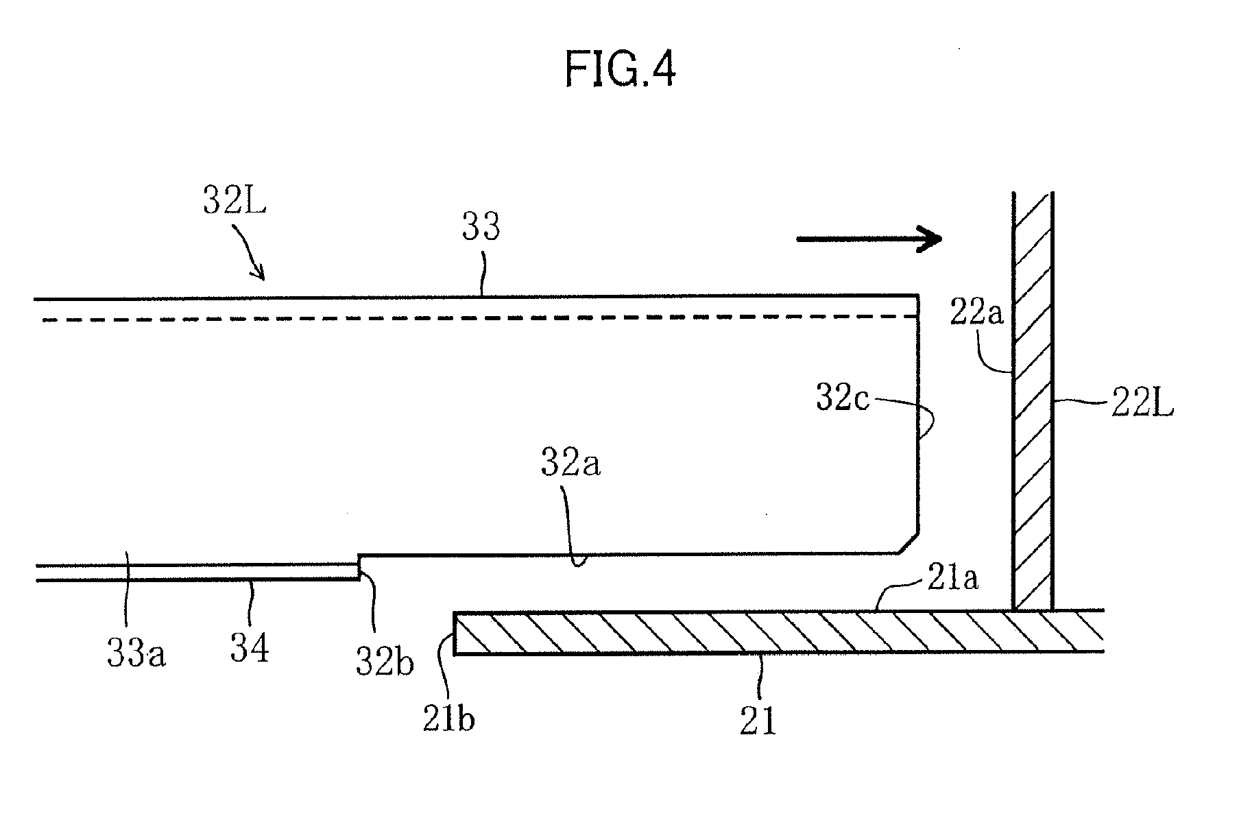
Fig. 4 is a cross-sectional view showing a state before a deck beam is combined to a longitudinal plate; -
Fig. 5 is a cross-sectional view showing a state where a height of a side deck is being adjusted; -
Fig. 6 is a cross-sectional view showing a state where the side deck has been welded to the center section; and -
Fig. 7 is a view corresponding toFig. 5 showing a configuration of a deck beam according to a modification of the present embodiment. - An embodiment of the present invention is described below with reference to the drawings. The following description of a preferred embodiment is essentially no more than description of exemplifications, and is not intended to limit the present invention and application or usage thereof. In
Fig. 1 , up and down, front and rear, and left and right directions are respectively indicated by arrowheads. Unless otherwise specifically stated, the up and down and other directions are described following the directions indicated by the arrowheads. -
Fig. 1 is a perspective view showing a configuration of a construction machine according to the embodiment of the present invention. As shown inFig. 1 , aconstruction machine 10 includes a lower runningbody 11, and an upper rotatingbody 12 rotatably supported on the lower runningbody 11. - The upper rotating
body 12 has anupper frame 15 that becomes a framework base thereof, aworking machine 13 derrickably fitted to theupper frame 15 at a front end part of theupper frame 15, acounterweight 16 fitted to a rear end side of theupper frame 15 to take weight balance with theworking machine 13, and acab 17 arranged at a portion at a left front side of theupper frame 15. - The working
machine 13 is for performing a digging operation and the like. The workingmachine 13 has aboom 13a having a base end part thereof turnably fitted to the upper rotatingbody 12, anarm 13b turnably fitted to a front end side of theboom 13a, and abucket 13c turnably fitted to a front end side of thearm 13b. Theboom 13a, thearm 13b, and thebucket 13c are respectively driven by a correspondinghydraulic cylinder 13d. - As shown in
Fig. 2 , a set ofmembers 15a configuring the upper frame includes acenter section 20 positioned at a central part in a vehicle width direction (a left and right direction), aleft side deck 30L coupled to a left side of thecenter section 20, and aright side deck 30R coupled to a right side of thecenter section 20.Fig. 3 shows anupper frame 15 configured by having both theside decks center section 20. - The
center section 20 has abottom plate 21, and a leftlongitudinal plate 22L and a rightlongitudinal plate 22R that are erected at inner sides than left and right edge parts of thebottom plate 21 and are extended in a front and rear direction. Thebottom plate 21 is formed by a thick steel plate. Thelongitudinal plates bottom plate 21 by welding. - The
left side deck 30L has aleft side frame 31L extended in a front and rear direction, andleft deck beams 32L for coupling theleft side frame 31 L to the leftlongitudinal plate 22L of thecenter section 20. Theright side deck 30R has aright side frame 31R extended in a front and rear direction, andright deck beams 32R for coupling theright side frame 31R to the rightlongitudinal plate 22R of thecenter section 20. Theleft deck beams 32L and theright deck beams 32R are respectively arranged by three, each having a gap in a front and rear direction. Specifically,first deck beams second deck beams Third deck beams - A front end part of each of the
side frames side frames center section 20 side. A rear end part of each of theside frames rear frame 37 that is extended from each of theside frames center section 20 side. Eachfront frame 36 and each front end part of thefirst deck beams coupling frame 38. - The
side decks center section 20. An end part of theleft deck beam 32L at a leftlongitudinal plate 22L side is brought into contact with anexternal side surface 22a of the leftlongitudinal plate 22L, and at the same time, an end part of theright deck beam 32R at a rightlongitudinal plate 22R side is brought into contact with an external side surface of the rightlongitudinal plate 22R so that these components in a contact state are welded to one another, whereby thecenter section 20 and theside decks - In welding the
side decks center section 20, height positions of theside decks center section 20 need to be adjusted. By devising configurations of thedeck beams side decks center section 20 is facilitated. - In the present embodiment, a configuration for facilitating height position adjustment relative to the
center section 20 is employed in theleft side deck 30L on which thecab 17 is mounted. That is, in the present embodiment, theleft deck beams 32L configure "adjustment deck beams" by which a height position relative to thecenter section 20 can be adjusted. Hereinafter, only theleft side deck 30L is described. A similar configuration may be also employed in theright side deck 30R. - In the
left side deck 30L, a firstleft deck beam 32L from the front and a secondleft deck beam 32L from the front are formed in closed cross-sectional shapes. The first and secondleft deck beams 32L havebeam members 33 that have a pair ofvertical plates 33a opposing each other in a front and rear direction and that are formed in cross-sectional concave shapes having openings at lower sides, and reinforcingplates 34 for coupling lower edge parts of the pair ofvertical plates 33a. Front end parts of the beam members 33 (end parts at a leftlongitudinal plate 22L side)configure contactingparts 32c that are brought into contact with theexternal side surface 22a of the leftlongitudinal plate 22L so that the contactingparts 32c can be welded to theexternal side surface 22a. Thebeam members 33 couple theleft side frame 31 L and the leftlongitudinal plate 22L. A thirdleft deck beam 32L from the front is formed by erecting one plate material, and couples theleft side frame 31 L and the leftlongitudinal plate 22L. That is, in the present embodiment, theleft side frame 31L configures an "adjustment frame", and the leftlongitudinal plate 22L configures an "adjustment-side longitudinal plate". - As shown in
Figs. 4 and 5 , a part of a lower part of each of the pair ofvertical plates 33a of thebeam members 33 at a leftlongitudinal plate 22L side is cut off. Accordingly, a second opposingpart 32a that is opposed to anupper surface 21a of thebottom plate 21 is formed by having a height-adjustment gap, at a lower part of thebeam member 33. The secondopposing part 32a has a shape extended in a direction parallel with a horizontal direction. - The reinforcing
plates 34 are arranged to have a predetermined distance in a left and right direction from a front end part (the contactingpart 32c) of thebeam member 33. As shown inFigs. 4 and 5 , a side surface of the reinforcingplate 34 is continuously extended downward from the second opposingpart 32a of thebeam member 33. The side surface of the reinforcingplate 34 configures a first opposingpart 32b that is opposed to aside surface 21b of thebottom plate 21 to enable the first opposingpart 32b to be welded to theside surface 21b when the contactingpart 32c of thebeam member 33 is brought into contact with theexternal side surface 22a of the leftlongitudinal plate 22L. The first opposingpart 32b has a shape extended to a direction parallel with a vertical direction that is vertical to the second opposingpart 32a. - When the contacting
part 32c of thebeam member 33 is brought into contact with theexternal side surface 22a of the leftlongitudinal plate 22L, the first opposingpart 32b of theleft deck beam 32L opposes theside surface 21b of thebottom plate 21. In this state, because a height-adjustment gap is formed in an up and down direction between the second opposingpart 32a of theleft deck beam 32L and theupper surface 21a of thebottom plate 21, theleft side deck 30L can be adjusted to a proper height position by sliding theleft side deck 30L in a height direction (an up and down direction) along a contact surface between the contactingpart 32c of theleft deck beam 32L and theexternal side surface 22a of the leftlongitudinal plate 22L and along an opposing surface between the side surface of the reinforcingplate 34 as the first opposingpart 32b and theside surface 21b of thebottom plate 21. - In the example shown in
Fig. 5 , although the side surface of the reinforcingplate 34 as the first opposingpart 32b and theside surface 21b of thebottom plate 21 are brought into contact with each other, a gap of a size (about 2 mm, for example)which permits welding may be provided between both side surfaces. By providing the gap, a size error of theleft deck beam 32L can be absorbed. This gap is set to a size small enough to allow the gap to be buried by welding the first opposingpart 32b to theside surface 21b of thebottom plate 21. - As shown in
Fig. 6 , after theleft side deck 30L is adjusted to a proper height position, a contact portion between the contactingpart 32c of thebeam member 33 and theexternal side surface 22a of the leftlongitudinal plate 22L, and an opposing portion between the side surface (the first opposingpart 32b) of the reinforcingplate 34 and theside surface 21b of thebottom plate 21 are welded respectively. As a result, theupper frame 15 is configured. At this time, height-position adjustment of theleft side deck 30L becomes easy, by first welding the opposing surface between the first opposingpart 32b and theside surface 21b of thebottom plate 21, and in this state by sliding theleft side deck 30L in a height direction (an up and down direction) along the contact surface between the contactingpart 32c and theexternal side surface 22a of the leftlongitudinal plate 22L. Therefore, it is preferable that theupper frame 15 is configured by first welding the opposing surface between the first opposingpart 32b and theside surface 21b of thebottom plate 21, then by adjusting a height position of theleft side deck 30L in this state, and last by welding the contact surface of the contactingpart 32c to theexternal side surface 22a of the leftlongitudinal plate 22L. - In the above configuration, by adjusting a height position of the
left side deck 30L using the first opposingpart 32b as a pivot point, a height position of theleft side deck 30L to thecenter section 20 becomes easy. Therefore, working efficiency improves. Further, a work of welding a height-adjustment member to a lower part of theleft deck beam 32L and the like can be omitted. This omission contributes to improve working efficiency and also contributes to cost reduction by decreasing the number of parts. - Further, because a load applied to the
left side deck 30L is dispersed to a welding portion between the contactingpart 32c of thebeam member 33 and theexternal side surface 22a of the leftlongitudinal plate 22L and to a welding portion between the side surface (the first opposingpart 32b) of the reinforcingplate 34 and theside surface 21b of thebottom plate 21, rigidity of theupper frame 15 is secured. - The above embodiment may be also configured as follows.
- In the above embodiment, an example of a configuration is described that the first
left deck beam 32L from the front and the secondleft deck beam 32L from the front respectively have the contactingpart 32c, the first opposingpart 32b, and the second opposingpart 32a. That is, the end part of thebeam member 33 at the leftlongitudinal plate 22L side configures the contactingpart 32c, the lower end part of each of the pair ofvertical plates 33a configures the second opposingpart 32a, and the side surface of the reinforcingplate 34 coupled to the lower part of thebeam member 33 configures the first opposingpart 32b. However, shapes of theleft deck beams 32L are not limited to the above example. For example, as shown inFig. 7 , the thirdleft deck beam 32L from the front, that is, theleft deck beam 32L formed by erecting one plate material, may be configured to have the contactingpart 32c, the first opposingpart 32b, and the second opposingpart 32a. Specifically, by cutting off a lower part of a front end part (an end part at a leftlongitudinal plate 22L side) of theleft deck beam 32L configured by a plate material, a remaining portion of the front end part of theleft deck beam 32L may configure the contactingpart 32c, and also this recessed portion may form the second opposingpart 32a and the first opposingpart 32b that is continuously extended downward from the second opposingpart 32a. - The number of the
left deck beam 32L may be one. - As described above, the present invention is extremely useful and has high industrial applicability because high practical utility is obtained that height adjustment of the side decks to the center section is facilitated and working efficiency can be improved in a simple configuration.
- The above detailed embodiment mainly includes inventions having the following configurations.
- The set of members forming an upper frame of a construction machine includes: a center section having a bottom plate, a left longitudinal plate erected at an inner side of a left edge part of the bottom plate, and a right longitudinal plate erected at an inner side of a right edge part of the bottom plate, the left longitudinal plate and the right longitudinal plate extended in a front and rear direction; a left side deck arranged at a left side of the center section; and a right side deck arranged at a right side of the center section. The left side deck has a left side frame extended in a front and rear direction, and a left deck beam for coupling the left side frame to the left longitudinal plate of the center section, and the right side deck has a right side frame extended in a front and rear direction, and a right deck beam for coupling the right side frame to the right longitudinal plate of the center section. At least one of the left deck beam or the right deck beam is an adjustment deck beam by which a height position relative to the center section can be adjusted. The adjustment deck beam has a contacting part that is adapted to be brought into contact with and is also adapted to be welded to an external side surface of an adjustment-side longitudinal plate opposing the adjustment deck beam out of the left longitudinal plate and the right longitudinal plate, a first opposing part that is adapted to be opposed to a side surface of the bottom plate and is also adapted to be welded to the side surface when the contacting part is brought into contact with the external side surface of the adjustment-side longitudinal plate, and a second opposing part that is adapted to be opposed to an upper surface of the bottom plate by having a height-adjustment gap in an up and down direction in a state where the contacting part is brought into contact with the external side surface of the adjustment-side longitudinal plate and also the first opposing part is opposed to the side surface of the bottom plate.
- According to the set of members, height adjustment of the side deck to the center section is facilitated, and working efficiency can be improved in a simple configuration. Specifically, when the contacting part of the adjustment deck beam is brought into contact with the external side surface of the adjustment-side longitudinal plate and also when the first opposing part is opposed to the side surface of the bottom plate, because a height-adjustment gap is formed between the second opposing part and the upper surface of the bottom plate, the side deck can be adjusted to proper height positions by sliding the side deck to a height direction along the contact surface between the contacting part and the external side surface of the adjustment-side longitudinal plate and along the opposing surface between the first opposing part and the side surface of the bottom plate. Therefore, the work of welding the height-adjustment member to a lower part of the deck beam and the like as conventionally required can be omitted. Consequently, working efficiency improves, and cost reduction can be achieved by decreasing the number of parts.
- After the side deck are adjusted to proper height positions, a contact portion between the contact part of the adjustment deck beam and the external side surfaces of the longitudinal plates, and a opposing portion between the first opposing part of the adjustment deck beam and the side surface of the bottom plate are welded respectively. As a result, the upper frame is configured. With this configuration, rigidity of the upper frame is secured because a load applied to each side deck is dispersed to a welding portion between the contacting part of the adjustment deck beam and the external side surface of the longitudinal plate and to a welding portion between the first opposing part of the adjustment deck beam and the side surface of the bottom plate.
- Further, in the set of members, it is preferable that the adjustment deck beam has: a beam member that has downward opening shapes and that couple an adjustment frame opposed to the adjustment-side longitudinal plate, out of the left side frame and the right side frame, to the adjustment-side longitudinal plate, an end part of the beam member at an adjustment-side longitudinal plate side configuring the contacting part; and a reinforcing plate that partially blocks the openings of the beam member. The reinforcing plate is arranged at a predetermined distance in a left and right direction from the contacting part such that when the contacting part of the beam member is brought into contact with the external side surface of the adjustment-side longitudinal plate, a portion of the reinforcing plate opposed to the side surface of bottom plate configures the first opposing part while a portion of the beam member opposed to an upper surface of the bottom plate configures the second opposing part.
- With the above configuration, rigidity of the adjustment-side deck beam can be secured while maintaining easiness of adjusting a height position of the side deck to the center section. Specifically, by arranging the reinforcing plate for securing rigidity of the adjustment-side deck beam to have a predetermined distance in a left and right direction from the contacting part of the beam member, rigidity of the adjustment-side deck beam can be secured because the adjustment-side deck beam is configured by the beam member and the reinforcing plate. Further, the second opposing part is formed in the beam member, and the side surface of the reinforcing plate function as the first opposing part.
- In the set of members, it is preferable that the first opposing part is opposed to the side surface of the bottom plate with a gap therebetween when the contacting part is brought into contact with the external side surface of the adjustment-side longitudinal plate, and the gap has a size small enough to allow the gap to be buried by welding between the first opposing part and the side surface of the bottom plate.
- With the above configuration, a welding work can be performed by absorbing a size error of the adjustment-side deck beam. Specifically, when a distance from the contacting part of the adjustment-side deck beam to the first opposing part is shorter than a distance from the external side surface of the adjustment-side longitudinal plate to the side surface of the bottom plate due to a size error of the adjustment-side deck beam, the first opposing part is brought into contact with the side surface of the bottom plate before the adjustment deck beam is brought into contact with the external side surface of the adjustment-side longitudinal plate. This has a problem in that a gap occurs between the contacting part of the adjustment deck beam and the external side surface of the adjustment-side longitudinal plate.
- On the other hand, according to the present invention, a size error of the adjustment deck beam is absorbed because a gap is provided between the first opposing part and the side surface of the bottom plate. Because this gap has a size (about 2 mm, for example)that permits welding, that is, a size small enough to allow the gap to be buried by welding the first opposing part to the side surface of the bottom plate, the welding work can be securely performed.
- Further, the present invention includes a manufacturing method for manufacturing the upper frame of a construction machine. The manufacturing method includes: a preparing process for preparing the set of members; an adjusting process for adjusting a height position in an up and down direction of each adjustment deck beam to the center section in a state where the contacting part is brought into contact with the external side surface of the adjustment-side longitudinal plate and also the first opposing part is opposed to the side surface of the bottom plate; and a welding process for welding, after the adjusting process, a contact portion between the contacting part and the external side surface of the adjustment-side longitudinal plate and an opposing portion between the first opposing part and the side surface of the bottom plate, respectively.
- According to the present manufacturing method, a height position of the side deck to the center section can be adjusted by only displacing the adjustment deck beam in an up and down direction in a state where the contacting part is brought into contact with the external side surface of the adjustment-side longitudinal plate and also the first opposing part is opposed to the side surface of the bottom plate. Further, the upper frame having sufficient rigidity can be easily configured by welding a contact portion between the contacting part and the external side surface of the adjustment-side longitudinal plate and an opposing portion between the first opposing part and the side surface of the bottom plate.
- This application is based on Japanese Patent application No.
2012-259536 - Although the present invention has been fully described by way of example with reference to the accompanying drawings, it is to be understood that various changes and modifications will be apparent to those skilled in the art. Therefore, unless otherwise such changes and modifications depart from the scope of the present invention hereinafter defined, they should be construed as being included therein.
- A set of members forming an upper frame of a construction machine includes a center section, a left side deck, and a right side deck. The left side deck has a left deck beam. The right side deck has a right deck beam. At least one of the left deck beam or the right deck beam is adjustment deck beams. The adjustment deck beam has a contacting part that is adapted to be brought into contact with and is also adapted to be welded to an external side surface of an adjustment-side longitudinal plate, a first opposing part that is adapted to be opposed to a side surface of the bottom plate and is also adapted to be welded to the side surface, and a second opposing part that is adapted to be opposed to an upper surface of the bottom plate with a height-adjustment gap therebetween.
Claims (4)
- A set of members forming an upper frame of a construction machine, comprising:a center section having a bottom plate, a left longitudinal plate erected at an inner side of a left edge part of the bottom plate, and a right longitudinal plate erected at an inner side of a right edge part of the bottom plate, the left longitudinal plate and the right longitudinal plate extended in a front and rear direction;a left side deck arranged at a left side of the center section; anda right side deck arranged at a right side of the center section, whereinthe left side deck has a left side frame extended in a front and rear direction, and a left deck beam for coupling the left side frame to the left longitudinal plate of the center section,the right side deck has a right side frame extended in a front and rear direction, and a right deck beam for coupling the right side frame to the right longitudinal plate of the center section,at least one of the left deck beam or the right deck beam is an adjustment deck beam by which a height position relative to the center section can be adjusted, andthe adjustment deck beam has a contacting part that is adapted to be brought into contact with and is also adapted to be welded to an external side surface of an adjustment-side longitudinal plate opposing the adjustment deck beam out of the left longitudinal plate and the right longitudinal plate, a first opposing part that is adapted to be opposed to a side surface of the bottom plate and is also adapted to be welded to the side surface when the contacting part is brought into contact with the external side surface of the adjustment-side longitudinal plate, and a second opposing part that is adapted to be opposed to an upper surface of the bottom plate by having a height-adjustment gap in an up and down direction in a state where the contacting part is brought into contact with the external side surface of the adjustment-side longitudinal plate and also the first opposing part is opposed to the side surface of the bottom plate.
- The set of members according to claim 1, wherein
the adjustment deck beam has: a beam member that has downward opening shapes and that couple an adjustment frame opposed to the adjustment-side longitudinal plate, out of the left side frame and the right side frame, to the adjustment-side longitudinal plate, an end part of the beam member at an adjustment-side longitudinal plate side configuring the contacting part; and a reinforcing plate that partially blocks the openings of the beam member, and
the reinforcing plate is arranged at a predetermined distance in a left and right direction from the contacting part such that when the contacting part of the beam member is brought into contact with the external side surface of the adjustment-side longitudinal plate, a portion of the reinforcing plate opposed to the side surface of bottom plate configures the first opposing part while a portion of the beam member opposed to an upper surface of the bottom plate configures the second opposing part. - The set of members according to claim 1, wherein
the first opposing part is opposed to the side surface of the bottom plate with a gap therebetween when the contacting part is brought into contact with the external side surface of the adjustment-side longitudinal plate, and the gap has a size small enough to allow the gap to be buried by welding between the first opposing part and the side surface of the bottom plate. - The set of members according to claim 2, wherein
the first opposing part is opposed to the side surface of the bottom plate with a gap therebetween when the contacting part is brought into contact with the external side surface of the adjustment-side longitudinal plate, and the gap has a size small enough to allow the gap to be buried by welding between the first opposing part and the side surface of the bottom plate.
Applications Claiming Priority (1)
| Application Number | Priority Date | Filing Date | Title |
|---|---|---|---|
| JP2012259536A JP2014105499A (en) | 2012-11-28 | 2012-11-28 | Upper frame of construction machine |
Publications (2)
| Publication Number | Publication Date |
|---|---|
| EP2738315A2 true EP2738315A2 (en) | 2014-06-04 |
| EP2738315A3 EP2738315A3 (en) | 2014-08-06 |
Family
ID=49724456
Family Applications (1)
| Application Number | Title | Priority Date | Filing Date |
|---|---|---|---|
| EP13194216.1A Withdrawn EP2738315A3 (en) | 2012-11-28 | 2013-11-25 | Set of members forming upper frame of construction machine |
Country Status (4)
| Country | Link |
|---|---|
| US (1) | US20140145471A1 (en) |
| EP (1) | EP2738315A3 (en) |
| JP (1) | JP2014105499A (en) |
| CN (1) | CN103850282A (en) |
Families Citing this family (5)
| Publication number | Priority date | Publication date | Assignee | Title |
|---|---|---|---|---|
| EP3212852A1 (en) | 2014-10-28 | 2017-09-06 | Caterpillar Global Mining LLC | Frame assembly for heavy duty vehicles |
| JP6296101B2 (en) * | 2016-06-22 | 2018-03-20 | コベルコ建機株式会社 | Construction machine upper frame |
| JP6458789B2 (en) * | 2016-09-26 | 2019-01-30 | コベルコ建機株式会社 | Work machine |
| JP7286414B2 (en) | 2019-05-24 | 2023-06-05 | キャタピラー エス エー アール エル | construction machine frame |
| JP7201536B2 (en) * | 2019-05-31 | 2023-01-10 | ヤンマーパワーテクノロジー株式会社 | construction machinery |
Citations (1)
| Publication number | Priority date | Publication date | Assignee | Title |
|---|---|---|---|---|
| JP2007030866A (en) | 2005-07-25 | 2007-02-08 | Volvo Construction Equipment Ab | Cab support upper frame structure in construction machine |
Family Cites Families (20)
| Publication number | Priority date | Publication date | Assignee | Title |
|---|---|---|---|---|
| US5445278A (en) * | 1986-12-18 | 1995-08-29 | G & G Intellectual Properties, Inc. | Adjustable vehicle-carrying frame for insertion into differently-sized containers |
| KR200168768Y1 (en) * | 1997-08-29 | 2000-02-01 | 추호석 | Swing frame of excavator |
| US6739624B2 (en) * | 1997-10-16 | 2004-05-25 | Magna International Inc. | Frame assembly for a motor vehicle |
| US6123378A (en) * | 1998-05-04 | 2000-09-26 | Aluminum Company Of America | Cross beam-main beam integral joint |
| JP3971521B2 (en) * | 1998-10-15 | 2007-09-05 | 本田技研工業株式会社 | Pillar joint structure for automobile |
| JP2002061226A (en) * | 2000-08-14 | 2002-02-28 | Hitachi Constr Mach Co Ltd | Slewing frame for construction machine |
| CA2466241C (en) * | 2001-11-09 | 2010-12-14 | Magna International Inc. | Modular underbody for a motor vehicle |
| US7374208B2 (en) * | 2003-03-18 | 2008-05-20 | Kobelco Construction Machinery Co., Ltd. | Working machine |
| US7255191B2 (en) * | 2003-10-31 | 2007-08-14 | Vectrix Corporation | Composite construction vehicle frame |
| DE10394337T5 (en) * | 2003-11-21 | 2006-10-12 | Raufoss Technology Asa | Subframe for a vehicle and method for its manufacture |
| US7857325B2 (en) * | 2005-12-16 | 2010-12-28 | Srats, Inc. | Adjustable-height suspension system |
| US7481350B1 (en) * | 2006-01-26 | 2009-01-27 | Shah Nitin J | Socket-welded pipe joint |
| JP4475241B2 (en) * | 2006-02-06 | 2010-06-09 | コベルコ建機株式会社 | Construction machine upper frame |
| JP4548375B2 (en) * | 2006-03-30 | 2010-09-22 | コベルコ建機株式会社 | Work machine |
| KR100753991B1 (en) * | 2006-09-22 | 2007-08-31 | 볼보 컨스트럭션 이키프먼트 홀딩 스웨덴 에이비 | Upper frame structure supporting the cab of the construction machine |
| US8414082B2 (en) * | 2008-07-25 | 2013-04-09 | Kubota Corporation | Work vehicle |
| JP5177201B2 (en) * | 2010-10-20 | 2013-04-03 | コベルコ建機株式会社 | Piping clamp for construction machinery |
| JP5668421B2 (en) * | 2010-11-10 | 2015-02-12 | コベルコ建機株式会社 | Construction machine upper frame |
| CN103189574B (en) * | 2010-11-15 | 2015-06-10 | 日立建机株式会社 | Construction machine swing frame |
| JP5278509B2 (en) * | 2011-07-27 | 2013-09-04 | コベルコ建機株式会社 | Device mounting method and apparatus for construction machinery |
-
2012
- 2012-11-28 JP JP2012259536A patent/JP2014105499A/en active Pending
-
2013
- 2013-11-20 US US14/085,097 patent/US20140145471A1/en not_active Abandoned
- 2013-11-25 EP EP13194216.1A patent/EP2738315A3/en not_active Withdrawn
- 2013-11-28 CN CN201310618752.XA patent/CN103850282A/en active Pending
Patent Citations (1)
| Publication number | Priority date | Publication date | Assignee | Title |
|---|---|---|---|---|
| JP2007030866A (en) | 2005-07-25 | 2007-02-08 | Volvo Construction Equipment Ab | Cab support upper frame structure in construction machine |
Also Published As
| Publication number | Publication date |
|---|---|
| US20140145471A1 (en) | 2014-05-29 |
| EP2738315A3 (en) | 2014-08-06 |
| CN103850282A (en) | 2014-06-11 |
| JP2014105499A (en) | 2014-06-09 |
Similar Documents
| Publication | Publication Date | Title |
|---|---|---|
| CA2842770C (en) | Excavator bucket and earth moving machine | |
| US20140145471A1 (en) | Set of members forming upper frame of construction machine | |
| US8079636B2 (en) | Cab for construction machine | |
| CN105164046A (en) | Mast assembly with improved operator visibility for a material handling vehicle | |
| EP2039591B1 (en) | Center frame in crawler travel device and method for manufacturing center frame | |
| EP2065293B1 (en) | Track frame for work machine | |
| EP3556717B1 (en) | Construction machine | |
| WO2015174552A1 (en) | Work vehicle cab and method for manufacturing same | |
| EP2281952B1 (en) | Construction machine | |
| JP4619147B2 (en) | Construction machinery | |
| US9243383B2 (en) | Working machine | |
| JP2015199427A (en) | work machine | |
| JP2011105032A (en) | Cab structure of working machine | |
| JP6174969B2 (en) | Construction machinery cab support structure | |
| KR20130116819A (en) | Clamshell bucket | |
| EP2975181A1 (en) | Work vehicle bucket and work vehicle provided with such bucket | |
| EP2980323B1 (en) | Cab for a construction machine | |
| JP5747786B2 (en) | Auxiliary platform structure for construction machinery | |
| JP6331836B2 (en) | Construction machinery | |
| JP2005144536A (en) | Bending method for differential thickness material and bending apparatus for differential thickness material | |
| EP2466016A1 (en) | Frame assembly and a method of manufacturing thereof | |
| KR101102515B1 (en) | Connecting device for work machine | |
| JP6694677B2 (en) | Revolving frame, and working machine equipped with it | |
| KR20060029281A (en) | Slewing Frame Structure of Construction Machinery | |
| KR101942213B1 (en) | Mounting structure of new boom |
Legal Events
| Date | Code | Title | Description |
|---|---|---|---|
| PUAI | Public reference made under article 153(3) epc to a published international application that has entered the european phase |
Free format text: ORIGINAL CODE: 0009012 |
|
| 17P | Request for examination filed |
Effective date: 20131125 |
|
| AK | Designated contracting states |
Kind code of ref document: A2 Designated state(s): AL AT BE BG CH CY CZ DE DK EE ES FI FR GB GR HR HU IE IS IT LI LT LU LV MC MK MT NL NO PL PT RO RS SE SI SK SM TR |
|
| AX | Request for extension of the european patent |
Extension state: BA ME |
|
| PUAL | Search report despatched |
Free format text: ORIGINAL CODE: 0009013 |
|
| AK | Designated contracting states |
Kind code of ref document: A3 Designated state(s): AL AT BE BG CH CY CZ DE DK EE ES FI FR GB GR HR HU IE IS IT LI LT LU LV MC MK MT NL NO PL PT RO RS SE SI SK SM TR |
|
| AX | Request for extension of the european patent |
Extension state: BA ME |
|
| RIC1 | Information provided on ipc code assigned before grant |
Ipc: E02F 9/08 20060101AFI20140701BHEP Ipc: B62D 33/02 20060101ALI20140701BHEP |
|
| STAA | Information on the status of an ep patent application or granted ep patent |
Free format text: STATUS: THE APPLICATION IS DEEMED TO BE WITHDRAWN |
|
| 18D | Application deemed to be withdrawn |
Effective date: 20150207 |