EP2738126A2 - Bobbin accommodating device and automatic winder - Google Patents
Bobbin accommodating device and automatic winder Download PDFInfo
- Publication number
- EP2738126A2 EP2738126A2 EP13184648.7A EP13184648A EP2738126A2 EP 2738126 A2 EP2738126 A2 EP 2738126A2 EP 13184648 A EP13184648 A EP 13184648A EP 2738126 A2 EP2738126 A2 EP 2738126A2
- Authority
- EP
- European Patent Office
- Prior art keywords
- bobbin
- section
- bobbins
- yarn
- bottom portion
- Prior art date
- Legal status (The legal status is an assumption and is not a legal conclusion. Google has not performed a legal analysis and makes no representation as to the accuracy of the status listed.)
- Granted
Links
Images






Classifications
-
- B—PERFORMING OPERATIONS; TRANSPORTING
- B65—CONVEYING; PACKING; STORING; HANDLING THIN OR FILAMENTARY MATERIAL
- B65H—HANDLING THIN OR FILAMENTARY MATERIAL, e.g. SHEETS, WEBS, CABLES
- B65H67/00—Replacing or removing cores, receptacles, or completed packages at paying-out, winding, or depositing stations
- B65H67/06—Supplying cores, receptacles, or packages to, or transporting from, winding or depositing stations
- B65H67/066—Depositing full or empty bobbins into a container or stacking them
-
- B—PERFORMING OPERATIONS; TRANSPORTING
- B65—CONVEYING; PACKING; STORING; HANDLING THIN OR FILAMENTARY MATERIAL
- B65H—HANDLING THIN OR FILAMENTARY MATERIAL, e.g. SHEETS, WEBS, CABLES
- B65H2701/00—Handled material; Storage means
- B65H2701/30—Handled filamentary material
- B65H2701/31—Textiles threads or artificial strands of filaments
Definitions
- the present invention relates to a bobbin accommodating device adapted to accommodate yarn absent bobbins discharged from a winding unit, and an automatic winder including the same.
- a bobbin tray type automatic winder e.g., includes a plurality of winding units, a bobbin transporting device, a yarn absent bobbin taking-out device, or the like.
- the bobbin transporting device transports to each of the winding units, a bobbin around which a yarn spun by a spinning machine is wound (hereinafter referred to as a yarn present bobbin).
- Each of the winding units forms a package by unwinding the yarn from the yarn present bobbin.
- bobbins of which yarn has been unwound in each winding unit are discharged from the winding unit.
- the discharged yarn absent bobbins are transported by trays of the bobbin transporting devices.
- the yarn absent bobbin taking-out device takes out the yarn absent bobbins on the trays of the bobbin transporting device.
- the yarn absent bobbins taken out by the yarn absent bobbin taking-out device are discharged from a yarn absent bobbin chute section.
- the discharged yarn absent bobbins are accommodated in a collection box, e.g.
- orientation of end portions thereof (a top-bottom direction) is made uniform.
- the yarn absent bobbins may jump or the like and change the orientation of the end portions thereof, leading to disarray with random orientations.
- the orientations of the end portions of the yarn absent bobbins needs to be made uniform again. Therefore, in a case where the orientations of the end portions of the yarn absent bobbins are random, an alignment task needs to be performed to make the orientations uniform before returning the yarn absent bobbins to the spinning machine.
- Japanese Unexamined Patent Publication No. 60-81338 discloses a device adapted to temporarily hold a yarn present bobbin (a fully-wound bobbin), which is not a yarn absent bobbin, in a hopper and to accommodate the yarn present bobbin in an accommodation box thereafter.
- the accommodation box is partitioned by a separator and the hopper is arranged in each compartment.
- 6-293473 discloses a device adapted to make orientation of end portions of yarn present bobbins (fully-wound bobbins) uniform while moving a chute and to hold the yarn present bobbins in a collection box.
- the device has a configuration in which the yarn present bobbins are sequentially collected one by one by moving the chute.
- the present invention is made to solve the above-described problem.
- the purpose of the present invention is to provide a bobbin accommodating device and an automatic winder that are capable of preventing the yarn absent bobbins from jumping in an accommodating section or the like, leading to a change in orientation of the end portions thereof, and collecting the yarn absent bobbins with uniform orientation of the end portions thereof.
- the bobbin accommodating device of a first invention is a bobbin accommodating device adapted to accommodate yarn absent bobbins discharged from a winding unit and includes an introduction port, a holding section and an accommodating section.
- the yarn absent bobbins are introduced into the introduction port.
- the holding section temporarily holds the yarn absent bobbins introduced through the introduction port while maintaining a uniform orientation of end portions thereof and, in a case where the amount of the yarn absent bobbins has reached a prescribed amount, discharges the held yarn absent bobbins.
- the accommodating section allocates into a plurality of compartments and accommodates the yarn absent bobbins discharged from the holding section.
- the holding section includes an allocating and discharging mechanism adapted to allocate the held yarn absent bobbins to each of the compartments of the accommodating section.
- a bobbin accommodating device of a second invention is the bobbin accommodating device of the first invention, in which the accommodating section is configured to be capable of installing therein, a collection box adapted to accommodate the yarn absent bobbins.
- the collection box has an interior portion divided into a plurality of compartments.
- a bobbin accommodating device of a third invention is the bobbin accommodating device of the first invention or the second invention, further including a held bobbin detecting sensor and a control section.
- the held bobbin detecting sensor is capable of detecting the amount of the yarn absent bobbins held in the holding section.
- the control section discharges from the holding section, the yarn absent bobbins held in the holding section based on a detection result of the held bobbin detecting sensor.
- a bobbin accommodating device of a fourth invention is the bobbin accommodating device of any one of the first invention through the third invention, in which the holding section includes a bottom portion for regulating a movement of the yarn absent bobbins in a vertical direction, which is a direction where the yarn absent bobbins fall, and a first side wall portion and a second side wall portion both for regulating a movement of the yarn absent bobbins in a horizontal direction.
- the allocating and discharging mechanism forms either of a first discharge port between the bottom portion and the first side wall portion or a second discharge port between the bottom portion and the second side wall portion by driving at least any one of the bottom portion, the first side wall portion and the second side wall portion.
- a bobbin accommodating device of a fifth invention is the bobbin accommodating device of the fourth invention, in which the bottom portion of the holding section is a rectangular plate member having long sides and short sides, and the first side wall portion and the second side wall portion are arranged along the long sides, which face each other, of the bottom portion.
- the allocating and discharging mechanism alternately forms the first discharge port and the second discharge port by simultaneously moving the first side wall portion and the second side wall portion with respect to the bottom portion.
- a bobbin accommodating device of a sixth invention is the bobbin accommodating device of the fourth invention or the fifth invention, in which the holding section is configured such that the bottom portion is removable.
- a bobbin accommodating device of a seventh invention is the bobbin accommodating device of the fourth invention, in which the bottom portion of the holding section includes a first bottom portion and a second bottom portion each having long sides and short sides, and the first side wall portion and the second side wall portion are arranged along the long sides, which face each other, of the bottom portion.
- the allocating and discharging mechanism alternately inclines the bottom portion to the first bottom portion side and to the second bottom portion side and, in a case where the bottom portion is inclined to the first bottom portion side, forms the first discharge port with the first side wall portion and, in a case where the bottom portion is inclined to the second bottom portion side, forms the second discharge port with the second side wall portion.
- a bobbin accommodating device of an eighth invention is the bobbin accommodating device of the seventh invention, in which the first bottom portion and the second bottom portion each having a base portion, a first receiving section and a second receiving section, are symmetric to each other, and while the first receiving section is arranged in a unified manner with the base portion in a side of the base portion where the first bottom portion and the second bottom portion are adjacent to each other, the second receiving section is arranged in a unified manner with the base portion in a side opposite to the side of the base portion where the first bottom portion and the second bottom portion are adjacent to each other.
- a shape of a cross section, which is formed by the base portion, the first receiving section and the second receiving section, in a direction vertical with respect to a swinging shaft of the first bottom portion and the second bottom portion is a recess.
- a bobbin accommodating device of a ninth invention is the bobbin accommodating device of any one of the fifth invention through the eighth invention, in which the holding section further includes a first-1 side wall portion and a first-2 side wall portion both arranged along the short sides of the bottomportion, and an adjustment mechanism adapted to adjust an interval between the first-1 side wall portion and the first-2 side wall portion.
- a bobbin accommodating device of a tenth invention is the bobbin accommodating device of any one of the third invention through the ninth invention, in which the accommodating section further includes a collection box detecting sensor adapted to detect an installation state of the collection box.
- the control section stops discharge of the yarn absent bobbins by the holding section in a case where it is detected based on a detection result of the collection box detecting sensor that the collection box is not installed in the accommodating section.
- a bobbin accommodating device of an eleventh invention is the bobbin accommodating device of the tenth invention, in which the collection box detecting sensor doubles as an accommodated bobbin amount detecting sensor adapted to detect the amount of the yarn absent bobbins accommodated in the collection box.
- the control section stops the discharge of the yarn absent bobbins by the holding section in a case where it is detected based on a detection result of the accommodated bobbin amount detecting sensor that the amount of the yarn absent bobbins accommodated in the collection box has reached a prescribed amount.
- a bobbin accommodating device of a twelfth invention is the bobbin accommodating device of the eleventh invention, in which at least two of each the holding section and the accommodating section are arranged side by side.
- a first accommodating section is set as a priority machine adapted to accommodate the yarn absent bobbins on a priority basis and a second accommodating section is set as an auxiliary machine adapted to accommodate the yarn absent bobbins in a case where the priority machine is unable to accommodate the yarn absent bobbins.
- An automatic winder of a thirteenth invention includes the bobbin accommodating device of any one of the first invention through the twelfth invention and a bobbin supplying device adapted to perform preparation processing for supplying the yarn present bobbins to the winding unit.
- the bobbin accommodating device is arranged on a part of the bobbin supplying device.
- An automatic winder of a fourteenth invention includes the bobbin accommodating device of the twelfth invention, a bobbin transporting device, a bobbin taking-out device and a yarn absent bobbin chute section.
- the bobbin transporting device collects the yarn absent bobbins from the winding unit.
- the bobbin taking-out device takes out the yarn absent bobbins from the bobbin transporting device.
- the yarn absent bobbin chute section guides the yarn absent bobbins that have been taken out by the bobbin taking-out device to the introduction port of the bobbin accommodating device while maintaining the uniform orientation of the end portions of the yarn absent bobbins that have been taken out.
- the yarn absent bobbin chute section determines according to a state of the priority machine whether to guide the yarn absent bobbins to the priority machine or the auxiliary machine.
- An automatic winder of a fifteenth invention is the automatic winder of the fourteenth invention, in which the yarn absent bobbin chute section includes a separator adapted to switch directions to guide the yarn absent bobbins between the prior machine and the auxiliary machine.
- the separator is arranged with a tip end portion thereof facing downstream and a swinging center thereof located upstream of the tip end portion.
- the yarn absent bobbins are prevented from jumping or the like, leading to a change in the orientation of the end portions thereof, thereby allowing the collection of the yarn absent bobbins with the uniform orientation of the end portions thereof.
- the automatic winder 100 of the present embodiment is a bobbin tray type automatic winder.
- the automatic winder 100 mainly includes a plurality of winding units 10, a bobbin transporting device 11, a bobbin supplying device 12, a bobbin taking-out device 13, and a bobbin accommodating device 40.
- Yarn present bobbins YB around which a yarn spun in a spinning machine (not illustrated) is wound are loaded in bulk in a container 8 and are transported to the bobbin supplying device 12, then are introduced into the bobbin supplying device 12.
- the bobbin supplying device 12 isolates one yarn present bobbin YB from a group of the introduced yarn present bobbins YB and mounts the yarn present bobbin YB by inserting the yarn present bobbin YB into a tray 22 of the bobbin transporting device 11.
- the bobbin transporting device 11 transports the yarn present bobbin YB to each of the winding units 10.
- Each of the winding units 10 forms a package by unwinding a yarn from the yarn present bobbin YB mounted to the tray 22.
- a processed yarn absent bobbin B of which yarn has been unwound in each winding unit 10 is discharged from the winding unit 10.
- the discharged yarn absent bobbin B is transported by the tray 22 of the bobbin transporting device 11.
- the yarn absent bobbin taking-out device 13 takes out the yarn absent bobbin B placed on the tray 22 of the bobbin transporting device 11.
- the taken-out yarn absent bobbin B is collected.
- a new yarn present bobbin YB is mounted downstream by the bobbin supplying device 12 to the tray 22 from which the yarn absent bobbin B has been taken out.
- a minimal residual yarn present bobbin which is a bobbin around which a considerably short yarn is wound, is also discharged, and the above-described yarn absent bobbin B includes the minimal residual yarn present bobbin.
- Each of the plurality of the winding units 10 arranged side by side is configured to unwind the yarn wound around the yarn present bobbin YB mounted to the tray 22 and to rewind the yarn around a winding bobbin to form a package.
- the bobbin transporting device 11 is configured to automatically supply the yarn present bobbin YB to each winding unit 10 and to collect the yarn absent bobbin B from each winding unit 10.
- the bobbin transporting device 11 includes a bobbin transport path 21 and a plurality of the trays 22.
- the bobbin transport path 21 transports the trays 22 by a conveyor and the like.
- the yarn present bobbin YB or the yarn absent bobbin B is mounted to a large number of the trays 22 transported on the bobbin transport path 21.
- the bobbin supplying device 12 is configured to supply the yarn present bobbin YB to the tray 22, on which neither the yarn present bobbin YB nor the yarn absent bobbin B are placed, of the transported trays 22.
- the bobbin supplying device 12 includes a bobbin introducing section 23, an isolating section 24, a tray placing section 25, and a bobbin moving section 26.
- the bobbin introducing section 23 is a section into which the group of yarn present bobbins YB, which has been transported by the container 8, is introduced.
- the isolating section 24 is configured to isolate the yarn present bobbin YB while elevating the group of the yarn present bobbins YB introduced into the bobbin introducing section 23.
- the isolating section 24 includes an endless belt 27 and a plurality of bobbin receiving members 28.
- the endless belt 27 is vertically arranged to constitute a conveyor.
- the plurality of bobbin receiving members 28 is mounted to the endless belt 27.
- a surface for having the yarn present bobbin YB placed thereon is arranged in the bobbin receiving member 28.
- the surface is configured to have only one yarn present bobbin YB thereon at a time.
- the yarn present bobbin YB transported to a lower part of the isolating section 24 is placed one by one on the bobbin receiving member 28 by the endless belt 27, which is circularly driven, and is transported upward. In such a manner, the yarn present bobbin YB in the bobbin introducing section 23 can be taken one by one and be isolated.
- the tray placing section 25 receives the yarn present bobbin YB transported upward by the isolating section 24 and determines an end portion on a side of unwinding the yarn present bobbin YB (a top side) and an end portion on a side of supporting the yarn present bobbin YB (a bottom side), then mounts the yarn present bobbin YB by inserting into the tray 22 of the bobbin transporting device 11 with the supporting end portion (the bottom side) downward.
- the tray 22 is in a stand-by state in a part below the tray placing section 25, and the yarn present bobbin YB is mounted by being inserted into the tray 22.
- the configuration of the tray placing section 25 is publicly known and is disclosed, e.g., in Japanese Patent Application Publication No. 8-169525 .
- the bobbin moving section 26 is arranged between the bobbin introducing section 23 and the isolating section 24 and is configured to move the group of the yarn present bobbins YB from the bobbin introducing section 23 to the isolating section 24.
- the bobbin moving section 26 includes a rocking and transporting section 29.
- the rocking and transporting section 29 is a member adapted to transport to the isolating section 24, a prescribed amount of yarn present bobbins YB of the group of the yarn present bobbins YB introduced into the bobbin introducing section 23 by rocking them.
- the rocking and transporting section 29 is configured to be driven and rocked between a position in which the rocking and transporting section 29 is inclined to the isolating section 24 side (a state in FIG. 2 ) and a position in which the rocking and transporting section 29 is inclined to the bobbin introducing section 23 side, which is a side opposite to the isolating section 24.
- the rocking and transporting section 29 in a state of being inclined to the isolating section 24 side blocks the group of the yarn present bobbins YB in the bobbin introducing section 23 from flowing into the isolating section 24.
- the rocking and transporting section 29 is rocked so as to be in a state of inclining to the bobbin introducing section 23 side.
- the blocked yarn present bobbins YB are placed on an upper surface of the rocking and transporting section 29.
- the rocking and transporting section 29 is rocked again so as to be in the state of inclining to the isolating section 24. Since the rocking and transporting section 29 is rocked in a state where a certain amount of the yarn present bobbins YB are placed thereon, only the yarn present bobbins YB, which are placed on the rocking and transporting section 29, are introduced into the isolating section 24. By rocking the rocking and transporting section 29, only the prescribed amount of the yarn present bobbins YB of the group of the yarn present bobbins YB in the bobbin introducing section 23 is transported to the isolating section 24.
- the bobbin taking-out device 13 is a device adapted to take out the yarn absent bobbin B from the tray 22, which has the yarn absent bobbin B discharged from the winding unit 10 placed thereon, among the trays 22 transported to the bobbin transporting device 11.
- the bobbin taking-out device 13 includes a frame 31, a belt member 32, a taking-out lever 33, a residual yarn present bobbin chute section 35, a yarn absent bobbin chute section 36, a residual yarn detecting sensor (not illustrated).
- a bobbin around which a small amount of yarn is wound may be mixed in the yarn absent bobbins B discharged from the winding unit 10.
- the frame 31 constitutes a base body of the bobbin taking-out device 13.
- the belt member 32 is a means for transporting the yarn absent bobbin B.
- the belt member 32 is an endless belt and is arranged towards a vertical direction.
- the taking-out lever 33 is an arm swingably arranged in the frame 31.
- a taking-out pulley 34 is arranged at a tip end of the taking-out lever 33.
- the taking-out lever 33 applies the taking-out pulley 34 to the yarn absent bobbin B on the tray 22 on the transport path 21 to move the yarn absent bobbin B to a side of the belt member 32, and thereafter takes out the yarn absent bobbin B upward from the tray 22 to feed to the belt member 32.
- the residual yarn detecting sensor (not illustrated) is a detection means for detecting the residual yarn present bobbin among the yarn absent bobbins B transported upward along the belt member 32.
- the residual yarn detecting sensor is arranged in a middle of a path where transportation is performed by the belt member 32.
- the residual yarn present bobbin chute section 35 and the yarn absent bobbin chute section 36 are arranged in the path where the belt member 32 transports the yarn absent bobbin B.
- the yarn absent bobbin B of which residual yarn has been detected by the residual yarn detecting sensor is discharged to the residual yarn present bobbin chute section 35 as a residual yarn present bobbin.
- the residual yarn bobbin chute section 35 is inclined, and slides the residual yarn present bobbin to introduce into a collection container (not illustrated) for the residual yarn bobbin.
- the yarn absent bobbin B having no residual yarn is discharged to the yarn absent bobbin chute section 36.
- the yarn absent bobbin chute section 36 is also inclined and slides the yarn absent bobbin B having no residual yarn to introduce it into the bobbin accommodating device 40.
- the yarn absent bobbin B is taken out with the end portion thereof on the unwinding side (the top side) facing upward. Therefore, the yarn absent bobbin B having no residual yarn is introduced from the yarn absent bobbin chute section 36 into the bobbin accommodating device 40 in a position in which the end portion thereof on the unwinding side (the top side) faces in a transporting direction.
- the yarn absent bobbin chute section 36 is arranged from the bobbin taking-out device 13 towards the bobbin accommodating device 40.
- a tip end portion of the yarn absent bobbin chute section 36 is branched into a first guiding path 371 and a second guiding path 372 respectively corresponding to the first introduction port 671 and the second introduction port 672.
- a separator 38 is installed at a branching portion of the first guiding path 371 and the second guiding path 372 of the yarn absent bobbin chute section 36.
- the separator 38 switches between the first introduction port 671 and the second introduction port 672 both serving as an introduction port of the yarn absent bobbin B by switching directions for guiding the yarn absent bobbin B.
- the separator 38 can be switched by a drive source (not illustrated). The switching is performed by a control section 77 arranged in the bobbin supplying device 12.
- a side of the bobbin taking-out device 13 of the yarn absent bobbin chute section 36 and a side of the bobbin accommodating device 40 are respectively referred to as upstream and downstream.
- a tip end portion 381 of the separator 38 in FIG. 3 faces upstream.
- a swinging shaft 382 is arranged downstream of the tip end portion 381.
- a position where the swinging shaft 382 is arranged is adjacent to the branching portion of the first guiding path 371 and the second guiding path 372 and is on a path where the yarn absent bobbin B passes through.
- the separator 38 switches the directions for guiding the yarn absent bobbin B by swinging the tip end portion 381 with the swinging shaft 382 as a center.
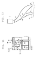
- FIG. 12 illustrates an alternative embodiment of the separator 38.
- the tip end portion 381 of the separator 38 in FIG. 12 faces downstream.
- the swinging shaft 382 is arranged upstream of the tip end portion 381.
- a position where the swinging shaft 382 is arranged is away from the branching portion of the first guiding path 371 and the second guiding path 372 and is off the path where the yarn absent bobbin B passes through.
- the separator 38 switches directions for guiding the yarn absent bobbin B by swinging the tip end portion 381 with the swinging shaft 382 as a center.
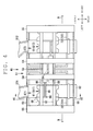
- the bobbin accommodating device 40 of the present invention As illustrated in FIG. 3 , in the present invention, the bobbin accommodating device 40 is installed above and across the rocking and transporting section 29 of the bobbin moving section 26.
- a side where the yarn absent bobbin B is introduced from the yarn absent bobbin chute section 36 is referred to as a front side of the bobbin accommodating device 40 and a side opposite to the front side is referred to as a rear side thereof.
- a right side and a left side of the bobbin accommodating device 40 are defined by viewing from the rear side.
- the bobbin accommodating device 40 includes a device main body 51, a holding section 61, and an accommodating section 71.
- a first holding section 611 and a first accommodating section 711 are respectively arranged as the holding section 61 and the accommodating section 71.
- a second holding section 612 and a second accommodating section 712 are respectively arranged as the holding section 61 and the accommodating section 71.
- the bobbin accommodating device 40 has a substantially left-right symmetric configuration, and the holding section 61 and the accommodating section 71 are substantially symmetric about a center in a left-right direction of the device main body 51.
- the device main body 51 is a part constituting a base body of the bobbin accommodating device 40.
- a front wall portion 52 is arranged in a front side of the device main body 51.
- the first introduction port 671 and the second introduction port 672 are arranged in the front wall portion 52 respectively corresponding to the first guiding path 371 and the second guiding path 372 of the yarn absent bobbin chute section 36.
- a cover (not illustrated) is arranged on an upper part of the device main body 51 to prevent the yarn absent bobbin B from bouncing out or the like when the automatic winder 100 is being operated.
- a rear wall portion 53 facing the front wall portion 52 is arranged in a rear side of the device main body 51.
- Upper surface portions of the front wall portion 52 and the rear wall portion 53 are coupled by a first coupling section 54 and a second coupling section 55.
- Two of the first coupling sections 54 are arranged parallel to each other near a center in the upper surface portions of the front wall portion 52 and the rear wall portion 53.
- the second coupling sections 55 are respectively arranged in left end portions and right end portions of the upper surface portions of the front wall portion 52 and the rear wall portion 53.
- Right side portions and left side portions of the front wall portion 52 and the rear wall portion 53 are coupled by a third coupling section 56 and a fourth coupling section 57.
- a fifth coupling section 58 Lower surface portions of the front wall portion 52 and the rear wall portion 53 are coupled by a fifth coupling section 58.
- a sixth coupling section 59 is arranged inside the device main body 51 so as to partition between a space where the first holding section 611 is installed and a space where the second holding section 612 is installed.
- An opening portion 70 is respectively arranged on a right side surface and a left side surface of the device main body 51 for moving a collection box 72 into/out of the accommodating section 71.
- the opening portion 70 is a region surrounded by the front wall portion 52, the rear wall portion 53, the fourth coupling section 57 and the fifth coupling section 58.
- the accommodating section 71 is adapted to accommodate the yarn absent bobbins B discharged from the holding section 61 in a plurality of compartments.
- the accommodating section 71 is configured to be capable of installing and replacing the collection box 72.
- the first accommodating section 711 and the second accommodating section 712 are arranged as the accommodating section 71.
- the first accommodating section 711 is configured to be capable of installing and replacing a first collection box 721
- the second accommodating section 712 is configured to be capable of installing and replacing a second collection box 722.
- Each interior portion of the first collection box 721 and the second collection box 722 is divided into a plurality of compartments.
- a placing section 73 adapted to place the collection box 72 is arranged in the accommodating section 71.
- the placing section 73 is configured to be capable of adjusting a position in a vertical direction according to a height of the collection box 72.
- a regulating section 74 is arranged in the placing section 73.
- the regulating section 74 is configured to be capable of adjusting a position in a front-rear direction with respect to the placing section 73 according to a front-rear size of the collection box 72.
- the first collection box 721 can be installed in a prescribed reference position.
- positions of the placing section 73 and the regulating section 74 are adjusted such that a front side and an upper end side of the first collection box 721 is positioned in the prescribed reference position.
- a partition 75 is mounted such that the interior portions of the first collection box 721 and the second collection box 722 are each divided into the plurality of compartments.
- each of the interior portions of the first collection box 721 and the second collection box 722 can be partitioned into two compartments.
- the first collection box 721 is partitioned by the partition 75 into a first compartment (1-1 compartment) 761 and a second compartment (1-2 compartment) 762.
- the second collection box 722 is partitioned by the partition 75 into a third compartment (2-1 compartment) 763 and a fourth compartment (2-2 compartment) 764.
- the first collection box 721 and the second collection box 722 are, in a state where the partition 75 is inserted, set such that a length of a short side of each compartment 761, 762, 763 and 764 is shorter than the length of the yarn absent bobbin B.
- a length of a long side of each compartment 761, 762, 763 and 764 is set to be slightly longer than the length of the yarn absent bobbin B.
- the partition 75 can be removed by upwardly taking out even in a state where the yarn absent bobbins B are accommodated in the first collection box 721 and the second collection box 722.
- the holding section 61 temporarily holds the yarn absent bobbins B introduced from the first introduction port 671 and the second introduction port 672 while maintaining a uniform orientation of end portions thereof.
- the first holding section 611 and the second holding section 612 are arranged as the holding section 61.
- the first holding section 611 allocates between the first compartment (1-1 compartment) 761 and the second compartment (1-2 compartment) 762 of the first collection box 721 and discharges the held yarn absent bobbins B.
- the second holding section 612 allocates between the third compartment (2-1 compartment) 763 and the fourth compartment (2-2 compartment) 764 of the second collection box 722 and discharges the held yarn absent bobbins B.
- the holding section 61 includes a bottom portion 62, a first side wall portion 63, a second side wall portion 64 and a third side wall portion 65.
- the bottom portion 62 is a member adapted to regulate a movement of the yarn absent bobbin B in a vertical direction, which is a direction where the yarn absent bobbins B fall.
- the bottom portion 62 is a rectangular plate member having long sides and short sides.
- the bottom portion 62 is, in the first holding section 611, installed above and across the partition 75 adapted to partition between the first compartment (1-1 compartment) 761 and the second compartment (1-2 compartment) 762 of the first collection box 721 and is, in the second holding section 612, installed above and across the partition 75 adapted to partition between the third compartment (2-1 compartment) 763 and the fourth compartment (2-2 compartment) 764 of the second collection box 722.
- the bottom portion 62 is inserted into a slit formed in the rear wall portion 53 and is supported by a slit arranged in the front wall portion 52. The bottom portion 62 can be removed from the device main body 51 by taking out from the slits.
- the first side wall portion 63, the second side wall portion 64 and the third side wall portion 65 are members for regulating movement of the yarn absent bobbin B in a horizontal direction (left-right direction).
- the first side wall portion 63, the second side wall portion 64 and the third side wall portion 65 are arranged along long sides, which face each other, of the bottom portion 62.
- the first side wall portion 63, the second side wall portion 64 and the third side wall portion 65 are configured by arranging side by side two identical shaped side wall members of which cross sections are both substantially U-shaped. Lower end portions of the side wall members 66 are slightly curbed inward.
- lower end portions of the first side wall portion 63 and the third side wall portion 65 are slightly curbed so as to be close to each other, and lower end portions of the second side wall portion 64 and the third side wall portion 65 are also slightly curbed so as to be close to each other.
- the front wall portion 52 as a first-1 side wall portion, and a first-2 side wall portion 68 are arranged in front and rear of the first side wall portion 63, the second side wall portion 64, and the third side wall portion 65.
- the front wall portion 52 (first-1 side wall portion) and the first-2 side wall portion 68 are members for regulating movement of the yarn absent bobbin B in a horizontal direction (front-back direction) (see FIG. 6 ).
- the first-2 side wall portion 68 is arranged across the first coupling section 54 and the second coupling section 55.
- the first-2 side wall portion 68 is extended such that a lower end portion thereof is adjacent to the bottom portion 62.
- the first-2 side wall portion 68 includes an adjustment mechanism for adjusting a position according to the length of the yarn absent bobbin B.
- the first-2 side wall portion 68 is configured to be capable of moving in the front-back direction, in a fixed position with respect to the first coupling section 54 and the second coupling section 55. This allows accommodation of the yarn absent bobbin B by adjusting the position of the first-2 side wall portion 68 even when the yarn absent bobbin B is replaced by a yarn absent bobbin B with a different length.
- a cushioning member 169 is mounted for reducing impact at the time of collision of the yarn absent bobbin B introduced from the yarn absent bobbin chute portion 36.
- a guiding section 87 is arranged in an upper part of the holding section 61.
- a through hole parallel to the left-right direction of the device main body 51 is formed in the guiding section 87, and a shaft 88 is formed through the through hole.
- the shaft 88 is arranged across the second coupling section 55 and the sixth coupling section 59 so as to be parallel to the left-right direction of the device main body 51.
- the holding section 61 can thus move in the left-right direction of the device main body 51 along the shaft 88.
- the first holding section 611 can switch positions between a state where the first side wall portion 63 and the third side wall portion 65 are above the bottom portion 62 (a state of the first holding section 611 illustrated in FIGS. 9A and 10C , which is hereinafter referred to as a "state 1-1") and a state where the second side wall portion 64 and the third side wall portion 65 are above the bottom portion 62 (a state of the first holding section 611 illustrated in FIGS. 9C and 10A , which is hereinafter referred to as a "state 1-2").
- the second holding section 612 also can independently switch positions between a state the first side wall portion 63 and the third side wall portion 65 are above the bottom portion 62 (hereinafter referred to as a "state 2-1") and a state where the second side wall portion 64 and the third side wall portion 65 is above the bottom portion 62 (hereinafter referred to as a "state 2-2").
- the holding section 61 includes an allocating and discharging mechanism 81 adapted to allocate the held yarn absent bobbins B to each compartment 761, 762, 763 and 764 of the accommodating section 71.
- the allocating and discharging mechanism 81 moves the first holding section 611 and the second holding section 612 to form a first discharge port 82 between the bottom portion 62 and the first side wall portion 63 (see FIG. 9B ) and a second discharge port 83 between the bottom portion 62 and the second side wall portion 64 (see FIG. 10B ).
- the allocating and discharging mechanism 81 includes an actuator 84.
- the actuator 84 is held in the first coupling section 54.
- a fixing section 86 is arranged in an upper part of the first holding section 611.
- a rod 85 of the actuator 84 is fixed to the fixing section 86.
- a held bobbin detecting sensor 91 is a sensor adapted to detect the amount of the yarn absent bobbins B held in the holding section 61.
- the held bobbin detecting sensor 91 detects the amount of the yarn absent bobbins B by detecting a position of an upper surface of the yarn absent bobbin B.
- a photoelectric sensor including a light projecting/receiving section 92 and a mirror section 93 is used as the held bobbin detecting sensor 91.
- the light projecting/receiving section 92 is arranged in the third coupling section 56 of the device main body 51.
- the mirror section 93 is arranged on the sixth coupling section 59 of the device main body 51.
- Through holes 99 are formed in each of the first side wall portion 63, the second side wall portion 64 and the third side wall portion 65 to allow light from the light projecting/receiving section 92 to reflect in the mirror section 93 through the through holes 99.
- the held bobbin detecting sensor 91 is configured such that when a prescribed amount of the yarn absent bobbins B is collected in the holding section 61, and thereafter the upper surface of the yarn absent bobbin B blocks the light from the light projecting/receiving section 92, the light projecting/receiving section 92 detects the blocked light and inputs a detection signal to a control section 77 (see FIGS. 9A and 10A ).
- the control section 77 activates the actuator 84 based on the detection signal from the held bobbin detecting sensor 91 to discharge from the holding section 61, the yarn absent bobbins B held in the holding section 61.
- the held bobbin detecting sensor 91 inputs the detection signal to the control section 77.
- the control section 77 activates the actuator 84 based on the detection signal from the held bobbin detecting sensor 91 to shift the first holding section 61 from the "state 1-1" in FIG. 9A to the "state 1-2" in FIG. 9C .
- the yarn absent bobbins B are continuously held from the state in FIG. 9C and, as illustrated in FIG. 10A , when a prescribed amount of the yarn absent bobbins B is held in the first holding section 611 under the "state 1-2", and thereafter the upper surface of the yarn absent bobbin B blocks light from the light projecting/receiving section 92, the held bobbin detecting sensor 91 inputs the detection signal to the control section 77. As illustrated in FIG. 10B , the control section 77 activates the actuator 84 based on the detection signal from the held bobbin detecting sensor 91 to shift the first holding section 611 from the "state 1-2" in FIG. 10A to the "state 1-1" in FIG. 10C .
- a collection box detecting sensor 94 is a sensor adapted to detect an installation state of the collection box 72.
- the collection box detecting sensor 94 is installed in each of the first accommodating section 711 and the second accommodating section 712.
- a photoelectric sensor including a light emitting section 95 and a light receiving section 96 is used as the collection box detecting sensor 94.
- a reflecting section 97 adapted to reflect light from the light emitting section 95 towards the light receiving section 96 is also arranged.
- the light emitting section 95 and the light receiving section 96 are arranged in the fourth coupling section 57 of the device main body 51.
- the reflecting section 97 is swingably supported by a shaft 98 arranged across an interior portion of the device main body 51 in a front-rear direction.
- the reflecting section 97 is pushed by the collection box 72, thereby being upright (see FIG. 8B ).
- the reflecting section 97 is, in a state of being upright, configured to reflect the light of the light emitting section 95 towards the light receiving section 96.
- the reflecting section 97 is in an inclined state (see FIG. 8A ).
- the reflecting section 97 is configured, in the inclined state, to reflect the light of the light emitting section 95 in a direction where the light receiving section 96 cannot receive the light.
- the collection box detecting sensor 94 is configured such that in a case where the collection box 72 is installed in the accommodating section 71, the light receiving section 96 detects the light from the light emitting section 95, which is reflected by the reflecting section 97, and inputs a detection signal to the control section 77.
- the control section 77 based on the detection signal from the collection box detecting sensor 94, brings the holding section 61 into a state where the yarn absent bobbins B can be discharged.
- the control section 77 based on the detection signal from the collection box detecting sensor 94, brings the holding section 61 into a state where the yarn absent bobbins B cannot be discharged.
- the collection box detecting sensor 94 doubles as an accommodated bobbin amount detecting sensor.
- the collection box detecting sensor 94 as the accommodated bobbin amount detecting sensor detects the amount of the yarn absent bobbins B accommodated in the collection box 72.
- the collection box detecting sensor 94 serving as the accommodated bobbin amount detecting sensor is configured such that when a prescribed amount of the yarn absent bobbins B is accommodated in the collection box 72, and thereafter the upper surface of the yarn absent bobbins B blocks the light from the light emitting section 95 or the light reflected from the reflecting section 97, the light receiving section 96 detects the blocked light and inputs the detection signal to the control section 77.
- the control section 77 activates a notifying section such as a lamp based on the detection signal from the collection box detecting sensor 94, which serves as the accommodated bobbin amount detecting sensor, to notify to an operator that the prescribed amount of the yarn absent bobbins B has been collected.
- a notifying section such as a lamp based on the detection signal from the collection box detecting sensor 94, which serves as the accommodated bobbin amount detecting sensor, to notify to an operator that the prescribed amount of the yarn absent bobbins B has been collected.
- priority is set between the first accommodating section 711 on a left side and the second accommodating section 712 on a right side.
- the first accommodating section 711 on the left side is set as a priority machine adapted to accommodate the yarn absent bobbins B on a priority basis.
- the second accommodating section 712 on the right side is set as an auxiliary machine adapted to accommodate the yarn absent bobbins B in a case where the first accommodating section 711 set as the priority machine is unable to accommodate the yarn absent bobbins B.
- Cases where the first accommodating section 711 is unable to accommodate the yarn absent bobbins B are: (1) a case where the yarn absent bobbins B are collected in the first collection box 721 of the first collecting section 711 and the amount thereof has reached a prescribed amount; and (2) a case where the first collection box 721 of the first accommodating section 711 is not installed (including a case of not being properly installed). In case (2), there is included a case where the operator is replacing the first collection box 721 after the yarn absent bobbins B are collected in the first collection box 721.
- the control section switches from the first introduction port 671 (the first accommodating section 711) to the second introduction port 672 (the second accommodating section 712).
- the bobbin accommodating device 40 includes the holding section 61 adapted to temporarily hold the yarn absent bobbins B while maintaining uniform orientation of the end portions thereof and the accommodating section 71 adapted to allocate to a plurality of compartments and to accommodate the yarn absent bobbins B discharged from the holding section 61. Since the holding section 61 collectively discharges a prescribed amount of the yarn absent bobbins B, the yarn absent bobbins B can be prevented from jumping in the accommodating section 71, leading to a change in the orientation of the end portions thereof, thereby allowing collection of the yarn absent bobbins with the uniform orientation of the end portions thereof.
- the yarn absent bobbins B held in the holding section 61 are allocated in the plurality of compartments of the accommodating section 71 and are discharged, the yarn absent bobbins B can be equally accommodated without being concentratedly discharged to one part of the accommodating section 71.
- the bobbin accommodating device 40 is configured to be capable of installing therein, the collection box 72 adapted to accommodate the yarn absent bobbins B.
- the collection box 72 has an interior portion divided into a plurality of compartments. Since the yarn absent bobbins B can be directly accommodated in the collection box 72, which the operator can handle, it is not required for the operator to collect the yarn absent bobbins B in another container for returning the yarn absent bobbins B to a spinning machine. Collecting operation of the yarn absent bobbins B can thus be easily performed in a short time.
- the bobbin accommodating device 40 causes the yarn absent bobbins B held in the holding section 61 to be discharged from the holding section 61. Since this allows the holding section 61 to hold an appropriate amount of the yarn absent bobbins B, the yarn absent bobbin B does not spill over the holding section 61. Furthermore, since the yarn absent bobbins B are not discharged to the accommodating section 71 in a small amount, the yarn absent bobbins B can be prevented from jumping in the accommodating section 71, leading to a change in the orientation of the end portions thereof.
- the allocating and discharging mechanism 81 moves the first side wall portion 63 and the second side wall portion 64 to form the first discharge port 82 between the bottom portion 62 and the first side wall portion 63, and the second discharge port 83 between the bottom portion 62 and the second side wall portion 64.
- the yarn absent bobbins B can thus be allocated with a simple configuration.
- the allocating and discharging mechanism 81 alternately forms the first discharge port 82 and the second discharge port 83.
- the yarn absent bobbins B held in the holding section 61 can thus be moved in a parallel manner and discharged to the accommodating section 71, thereby allowing suppression of impact of the yarn absent bobbins B at the time of discharging the yarn absent bobbins B to the accommodating section 71.
- the bottom portion 62 is configured in a removable manner. Therefore, in cases where the yarn absent bobbins B are stuck in the holding section 61, or the like, the operator can easily perform maintenance on the holding section 61 by removing the bottom portion 62.
- the holding section 61 includes the front wall portion 52 as the first-1 side wall portion and the first-2 side wall portion 68 both arranged along short sides of the bottom portion 62, and an adjustment mechanism (not illustrated) adapted to adjust an interval of the front wall portion 52 as the first-1 side wall portion and the first-2 side wall portion 68. Therefore, size of the holding section 61 in a longitudinal direction can be adjusted in accordance with the size of the yarn absent bobbins B to be temporarily held, thereby allowing accommodation of a plurality of types of the yarn absent bobbins B.
- the bobbin accommodating device 40 stops the discharge of the yarn absent bobbins B by the holding section 61.
- the yarn absent bobbins B can thus be prevented from being discharged from the holding section 61 in a state where the collection box 72 is not installed in the accommodating section 71.
- the collection box detecting sensor 94 doubles as the accommodated bobbin amount detecting sensor adapted to detect the amount of the yarn absent bobbins B accommodated in the collection box 72. Since the collection box detecting sensor 94 doubles as the accommodated bobbin amount detecting sensor, the number of sensors can be reduced. Furthermore, when the accommodated bobbin amount detecting sensor detects that the amount of the yarn absent bobbins B accommodated in the collection box 72 has reached a prescribed amount, the discharge of the yarn absent bobbins B from the holding section 61 is stopped, thereby preventing the yarn absent bobbins B from spilling over the collection box 72.
- the bobbin accommodating device 40 includes at least two of each the holding section 61 and the accommodating section 71 arranged side by side.
- the first accommodating section 711 is set as the priority machine adapted to accommodate the yarn absent bobbins B on a priority basis and the second accommodating section 712 is set as the auxiliary machine adapted to accommodate the yarn absent bobbins B in a case where the priority machine is unable to accommodate the yarn absent bobbins B.
- the bobbin accommodating device 40 is arranged on a part of the bobbin supplying device 12. This allows supply of the yarn present bobbins YB and accommodation of the yarn absent bobbins B both to be performed in positions adjacent to each other, thereby minimizing movement of the operator. Furthermore, a space required for installing the automatic winder 100 can be reduced.
- the yarn absent bobbin chute section 36 determines whether to guide the yarn absent bobbins B to the priority machine or to the auxiliary machine according to a state of the priority machine. Thus, even when collecting operation of the yarn absent bobbins B is being performed in one of the accommodating sections 71, the yarn absent bobbins B can be continuously accommodated in the other of the collecting sections 71.
- Embodiment 2 Next, an automatic winder according to Embodiment 2 of the present invention will be described by use of FIGS. 13 to 17 .
- the automatic winder of the second embodiment is mainly different from the automatic winder 100 of Embodiment 1 in terms of a configuration of a holding section 61' of a bobbin accommodating device 140, however, identical collection boxes 72, 721, 722 may be used.
- the bobbin accommodating device 140 includes a device main body 51', the holding section 61' and an accommodating section 71'.
- a first holding section 611' and a second holding section 612' are arranged as the holding section 61'.
- the first holding section 611' allocates the held yarn absent bobbins B between the first compartment (1-1 compartment) 761 and the second compartment (1-2 compartment) 762 of the first collection box 721 and discharges the held yarn absent bobbins B.
- the second holding section 612' allocates the held yarn absent bobbins B between the third compartment (2-1 compartment) 763 and the fourth compartment (2-2 compartment) 764 of the second collection box 722 and discharges the held yarn absent bobbins B.
- the holding section 61' includes the bottom portion 62', the first side wall portion 63' and the second side wall portion 64'.
- the bottom portion 62' is a member adapted to regulate movement of the yarn absent bobbins B in a vertical direction, which is a direction where the yarn absent bobbins B fall.
- the bottom portion 62' includes a first bottom portion 621 and a second bottom portion 622 both having long sides and short sides.
- the first bottom portion 621 and the second bottom portion 622 each has a shape symmetric to each other.
- the first bottom portion 621 and the second bottom portion 622 are swingably arranged with respect to the device main body 51' with a shaft 67 as an axial center.
- the first bottom portion 621 and the second bottom portion 622 each has a base portion 623, a first receiving section 624 and a second receiving section 625.
- the first receiving section 624 and the second receiving section 625 are each arranged in a unified manner with the base portion 623 on a side of the base portion 623.
- the first receiving section 624 is arranged in a unified manner with the base portion 623 on a side of the base portion 623 where the first bottom portion 621 and the second bottom portion 622 are adjacent to each other
- the second receiving section 625 is arranged in a unified manner with the base portion 623 on a side opposite to the side of the base portion 623 where the first bottom portion 621 and the second bottom portion 622 are adjacent to each other.
- a shape of a cross section formed by cutting the first bottom portion 621 and the second bottom portion 622 vertically with respect to the shaft 67 is a recess such that the base portion 623, the first receiving section 624 and the second receiving section 625 can hold the yarn absent bobbins B.
- the first bottom portion 621 and the second bottom portion 622 are mounted to a fixing section 66', each arranging the first receiving section 624 adjacent to each of them.
- the second receiving section 625 is inverted at substantially 90 degrees with respect to the first receiving section 624.
- the fixing section 66' is mounted to the shaft 67.
- the shaft 67 is rotatably arranged across the front wall portion 52 and the rear wall portion 53 of the device main body 51'.
- the shaft 67 is, in the first holding section 611', installed above and across the partition 75 adapted to partition between the first compartment (1-1 compartment) 761 and the second compartment (1-2 compartment) 762 of the first collection box 721 and is, in the second holding section 612', installed above and across the third compartment (2-1 compartment) 763 and the fourth compartment (2-2 compartment) 764 of the second collection box 722.
- the first side wall portion 63' and the second side wall portion 64' are members adapted to regulate movement of the yarn absent bobbin B in a horizontal direction (left-side direction).
- the first side wall portion 63' is arranged along a free end of the second receiving section 625 of the first bottom portion 621.
- the second side wall portion 64' is arranged along a free end of the second receiving section 625 of the second bottom portion 622.
- the first side wall portion 63' and the second side wall portion 64' are supported by each swinging section 68'.
- Each swinging section 68' is arranged on a shaft 69 in a hanging manner.
- the shaft 69 is arranged across the front wall portion 52 and the rear wall portion 53. The first side wall portion 63' and the second side wall portion 64' can thus be swung with respect to the device main body 51.
- a cam 87' as the guiding section 87 is fixed to the shaft 67, which supports the bottom portion 62, in a side of the front side wall portion 52 of the device main body 51'.
- a follower 89 which abuts against the cam 87', is arranged in the swinging section 68' adapted to support the first side wall portion 63' and the second side wall portion 64'.
- the cam 87' has a shape by which the cam 87' pushes up the first side wall portion 63' via the follower 89 to form a first discharge port 82' between the first bottom portion 621 and the first side wall portion 63' (see FIG.
- a second discharge port 83' between the second bottom portion 622 and the second side wall portion 64' is closed since the second side wall portion 64' is not pushed up.
- the cam 87' has a shape by which the cam 87' pushes up the second side wall portion 64 via the follower 89 to form the second discharge port 83' between the second bottom portion 622 and the second side wall portion 63' (see FIG. 17B ) and at this time, the first discharge port 82' between the first bottom portion 621 and the first side wall portion 63' is closed since the first side wall portion 63' is not pushed up.
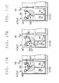
- the first holding section 611 is capable of switching positions between a state where the bottom portion 62' is inclined to the second bottom portion 622 side and the first discharge port 82' between the first bottom portion 621 and the first side wall portion 63' is closed (a state of the first holding section 611' illustrated in FIGS. 16A and 17C , which is hereinafter referred to as a "state 3-1") and a state where the bottom portion 62' is inclined to the first bottom portion 621 side and the second discharge port 83' between the second bottom portion 622 and the second side wall portion 64' is closed (a state of the first holding section 611' illustrated in FIGS. 16C and 17A , which is hereinafter referred to as a "state 3-2").
- the second holding section 612' is also capable of switching positions between a state where the bottom portion 62' is inclined to the second bottom portion 622 side and the first discharge port 82' between the first bottom portion 621 and the first side wall portion 63' is closed (hereinafter referred to as a "state 4-1") and a state where the bottom portion 62' is inclined to the first bottom portion 621 side and the second discharge port 83' between the second bottom portion 622 and the second side wall portion 64' is closed (hereinafter referred to as a "state 4-2").
- the holding section 61' includes an allocating and discharging mechanism 181 adapted to allocate the held yarn absent bobbins B to each compartment 761, 762, 763 and 764 of the accommodating section 71.
- the allocating and discharging mechanism 181 moves (swings) the first holding section 611 and the second holding section 612 to form the first discharge port 82' between the bottom portion 62' and the first side wall portion 63' (see FIG. 16B ) and the second discharge port 83' between the bottom portion 62' and the second side wall portion 64' (see FIG. 17B ).
- the allocating and discharging mechanism 181 includes an actuator 84'.
- the actuator 84' is arranged in an outer side of the front wall portion 52.
- the actuator 84' includes an extendable rod 85'.
- a lever 86' is arranged in the shaft 67, which supports the bottom portion 62'.
- the rod 85' of the actuator 84' is coupled to the lever 86'.
- the held bobbin detecting sensor 91 is a sensor adapted to detect the amount of the yarn absent bobbins B held in the holding section 61'.
- a photoelectric sensor including the light projecting/receiving section 92 and the mirror section 93 is used as the held bobbin detecting sensor 91.
- a configuration is made such that when a prescribed amount of the yarn absent bobbins B is collected in the holding section 61', and thereafter an upper surface of the yarn absent bobbin B blocks light from the light projecting/receiving section 92, the light projecting/receiving section 92 detects the blocked light and inputs a detection signal to the control section 77 (see FIGS. 16A and 17A ).
- the control section 77 activates the actuator 84' based on the detection signal from the held bobbin detecting sensor 91 to discharge from the holding section 61' the yarn absent bobbins B held in the holding section 61.
- the control section 77 activates the actuator 84' based on the detection signal from the held bobbin detecting sensor 91 to shift the first holding section 611' from the "state 3-1" in FIG. 16A to the "state 3-2" in FIG. 16C .
- the yarn absent bobbins B are continuously held from the state in FIG. 16C and as illustrated in FIG. 17A , when a prescribed amount of the yarn absent bobbins B is held in the first holding section 611' under the "state 3-2", and thereafter the upper surface of the yarn absent bobbin B blocks the light from the light projecting/receiving section 92, the held bobbin detecting sensor 91 inputs the detection signal to the control section 77. As illustrated in FIG. 17B , the control section 77 activates the actuator 84' based on the detection signal from the held bobbin detecting sensor 91 to shift the first holding section 611' from the "state 3-2" in FIG. 17A to the "state 3-1" in FIG. 17C .
- the allocating and discharging mechanism 181 alternately inclines the bottom portion 62' to the first bottom portion 621 side and the second bottom portion 622 side.
- the allocating and discharging mechanism 181 forms the first discharge port 82' with the first side wall portion 63' in a case where the bottom portion 62' is inclined to the first bottom portion 621 side, and forms the second discharge port 83' with the second side wall portion 64' in a case where the bottom portion 62' is inclined to the second bottom portion 622 side.
- the yarn absent bobbins B can thus be discharged without being sandwiched by the first discharge port 82', the second discharge port 83', and the like.
- the first bottom portion 621 and the second bottom portion 622 each having the base portion 623, the first receiving section 624 and the second receiving section 625, are symmetric to each other.
- the first receiving section 624 is arranged in a unified manner with the base portion 623 on a side of the bottom portion 623 where the first bottom portion 621 and the second bottom portion 622 are adjacent to each other
- the second receiving section 625 is arranged in a unified manner with the base portion 623 on a side opposite to the side of the base portion 623 where the first bottom portion 621 and the second bottom portion 622 are adjacent to each other.
Landscapes
- Replacing, Conveying, And Pick-Finding For Filamentary Materials (AREA)
Abstract
Description
- The present invention relates to a bobbin accommodating device adapted to accommodate yarn absent bobbins discharged from a winding unit, and an automatic winder including the same.
- Conventionally, there is known an automatic winder configured by arranging a plurality of winding units side by side. A bobbin tray type automatic winder, e.g., includes a plurality of winding units, a bobbin transporting device, a yarn absent bobbin taking-out device, or the like. The bobbin transporting device transports to each of the winding units, a bobbin around which a yarn spun by a spinning machine is wound (hereinafter referred to as a yarn present bobbin). Each of the winding units forms a package by unwinding the yarn from the yarn present bobbin.
- Processed bobbins of which yarn has been unwound in each winding unit (hereinafter referred to as a yarn absent bobbin) are discharged from the winding unit. The discharged yarn absent bobbins are transported by trays of the bobbin transporting devices. The yarn absent bobbin taking-out device takes out the yarn absent bobbins on the trays of the bobbin transporting device. The yarn absent bobbins taken out by the yarn absent bobbin taking-out device are discharged from a yarn absent bobbin chute section. The discharged yarn absent bobbins are accommodated in a collection box, e.g.
- When the yarn absent bobbins are discharged from the yarn absent bobbin chute section, orientation of end portions thereof (a top-bottom direction) is made uniform. However, after the yarn absent bobbins pass through the yarn absent bobbin chute section and are haphazardly introduced into the collection box or the like, the yarn absent bobbins may jump or the like and change the orientation of the end portions thereof, leading to disarray with random orientations. When returning the yarn absent bobbins to the spinning machine thereafter, the orientations of the end portions of the yarn absent bobbins needs to be made uniform again. Therefore, in a case where the orientations of the end portions of the yarn absent bobbins are random, an alignment task needs to be performed to make the orientations uniform before returning the yarn absent bobbins to the spinning machine.
- As an art of collecting the bobbins in the collection box or the like with uniform orientation of the end portions of the bobbins, Japanese Unexamined Patent Publication No.
60-81338 6-293473 - The present invention is made to solve the above-described problem. The purpose of the present invention is to provide a bobbin accommodating device and an automatic winder that are capable of preventing the yarn absent bobbins from jumping in an accommodating section or the like, leading to a change in orientation of the end portions thereof, and collecting the yarn absent bobbins with uniform orientation of the end portions thereof.
- The problem to be solved by the present invention is as mentioned above, and now, the means for solving such problem will be described below.
- That is, the bobbin accommodating device of a first invention is a bobbin accommodating device adapted to accommodate yarn absent bobbins discharged from a winding unit and includes an introduction port, a holding section and an accommodating section. The yarn absent bobbins are introduced into the introduction port. The holding section temporarily holds the yarn absent bobbins introduced through the introduction port while maintaining a uniform orientation of end portions thereof and, in a case where the amount of the yarn absent bobbins has reached a prescribed amount, discharges the held yarn absent bobbins. The accommodating section allocates into a plurality of compartments and accommodates the yarn absent bobbins discharged from the holding section. The holding section includes an allocating and discharging mechanism adapted to allocate the held yarn absent bobbins to each of the compartments of the accommodating section.
- A bobbin accommodating device of a second invention is the bobbin accommodating device of the first invention, in which the accommodating section is configured to be capable of installing therein, a collection box adapted to accommodate the yarn absent bobbins. The collection box has an interior portion divided into a plurality of compartments.
- A bobbin accommodating device of a third invention is the bobbin accommodating device of the first invention or the second invention, further including a held bobbin detecting sensor and a control section. The held bobbin detecting sensor is capable of detecting the amount of the yarn absent bobbins held in the holding section. The control section discharges from the holding section, the yarn absent bobbins held in the holding section based on a detection result of the held bobbin detecting sensor.
- A bobbin accommodating device of a fourth invention is the bobbin accommodating device of any one of the first invention through the third invention, in which the holding section includes a bottom portion for regulating a movement of the yarn absent bobbins in a vertical direction, which is a direction where the yarn absent bobbins fall, and a first side wall portion and a second side wall portion both for regulating a movement of the yarn absent bobbins in a horizontal direction. The allocating and discharging mechanism forms either of a first discharge port between the bottom portion and the first side wall portion or a second discharge port between the bottom portion and the second side wall portion by driving at least any one of the bottom portion, the first side wall portion and the second side wall portion.
- A bobbin accommodating device of a fifth invention is the bobbin accommodating device of the fourth invention, in which the bottom portion of the holding section is a rectangular plate member having long sides and short sides, and the first side wall portion and the second side wall portion are arranged along the long sides, which face each other, of the bottom portion. The allocating and discharging mechanism alternately forms the first discharge port and the second discharge port by simultaneously moving the first side wall portion and the second side wall portion with respect to the bottom portion.
- A bobbin accommodating device of a sixth invention is the bobbin accommodating device of the fourth invention or the fifth invention, in which the holding section is configured such that the bottom portion is removable.
- A bobbin accommodating device of a seventh invention is the bobbin accommodating device of the fourth invention, in which the bottom portion of the holding section includes a first bottom portion and a second bottom portion each having long sides and short sides, and the first side wall portion and the second side wall portion are arranged along the long sides, which face each other, of the bottom portion. The allocating and discharging mechanism alternately inclines the bottom portion to the first bottom portion side and to the second bottom portion side and, in a case where the bottom portion is inclined to the first bottom portion side, forms the first discharge port with the first side wall portion and, in a case where the bottom portion is inclined to the second bottom portion side, forms the second discharge port with the second side wall portion.
- A bobbin accommodating device of an eighth invention is the bobbin accommodating device of the seventh invention, in which the first bottom portion and the second bottom portion each having a base portion, a first receiving section and a second receiving section, are symmetric to each other, and while the first receiving section is arranged in a unified manner with the base portion in a side of the base portion where the first bottom portion and the second bottom portion are adjacent to each other, the second receiving section is arranged in a unified manner with the base portion in a side opposite to the side of the base portion where the first bottom portion and the second bottom portion are adjacent to each other. A shape of a cross section, which is formed by the base portion, the first receiving section and the second receiving section, in a direction vertical with respect to a swinging shaft of the first bottom portion and the second bottom portion is a recess.
- A bobbin accommodating device of a ninth invention is the bobbin accommodating device of any one of the fifth invention through the eighth invention, in which the holding section further includes a first-1 side wall portion and a first-2 side wall portion both arranged along the short sides of the bottomportion, and an adjustment mechanism adapted to adjust an interval between the first-1 side wall portion and the first-2 side wall portion.
- A bobbin accommodating device of a tenth invention is the bobbin accommodating device of any one of the third invention through the ninth invention, in which the accommodating section further includes a collection box detecting sensor adapted to detect an installation state of the collection box. The control section stops discharge of the yarn absent bobbins by the holding section in a case where it is detected based on a detection result of the collection box detecting sensor that the collection box is not installed in the accommodating section.
- A bobbin accommodating device of an eleventh invention is the bobbin accommodating device of the tenth invention, in which the collection box detecting sensor doubles as an accommodated bobbin amount detecting sensor adapted to detect the amount of the yarn absent bobbins accommodated in the collection box. The control section stops the discharge of the yarn absent bobbins by the holding section in a case where it is detected based on a detection result of the accommodated bobbin amount detecting sensor that the amount of the yarn absent bobbins accommodated in the collection box has reached a prescribed amount.
- A bobbin accommodating device of a twelfth invention is the bobbin accommodating device of the eleventh invention, in which at least two of each the holding section and the accommodating section are arranged side by side. A first accommodating section is set as a priority machine adapted to accommodate the yarn absent bobbins on a priority basis and a second accommodating section is set as an auxiliary machine adapted to accommodate the yarn absent bobbins in a case where the priority machine is unable to accommodate the yarn absent bobbins.
- An automatic winder of a thirteenth invention includes the bobbin accommodating device of any one of the first invention through the twelfth invention and a bobbin supplying device adapted to perform preparation processing for supplying the yarn present bobbins to the winding unit. The bobbin accommodating device is arranged on a part of the bobbin supplying device.
- An automatic winder of a fourteenth invention includes the bobbin accommodating device of the twelfth invention, a bobbin transporting device, a bobbin taking-out device and a yarn absent bobbin chute section. The bobbin transporting device collects the yarn absent bobbins from the winding unit. The bobbin taking-out device takes out the yarn absent bobbins from the bobbin transporting device. The yarn absent bobbin chute section guides the yarn absent bobbins that have been taken out by the bobbin taking-out device to the introduction port of the bobbin accommodating device while maintaining the uniform orientation of the end portions of the yarn absent bobbins that have been taken out. The yarn absent bobbin chute section determines according to a state of the priority machine whether to guide the yarn absent bobbins to the priority machine or the auxiliary machine.
- An automatic winder of a fifteenth invention is the automatic winder of the fourteenth invention, in which the yarn absent bobbin chute section includes a separator adapted to switch directions to guide the yarn absent bobbins between the prior machine and the auxiliary machine. In a case where a side of the bobbin taking-out device of the yarn absent bobbin chute section is upstream and a side of the bobbin accommodating device is downstream, the separator is arranged with a tip end portion thereof facing downstream and a swinging center thereof located upstream of the tip end portion.
- With the bobbin accommodating device and the automatic winder of the present invention, the yarn absent bobbins are prevented from jumping or the like, leading to a change in the orientation of the end portions thereof, thereby allowing the collection of the yarn absent bobbins with the uniform orientation of the end portions thereof.
-
-
FIG. 1 is a simplified front view illustrating an automatic winder according toEmbodiment 1; -
FIG. 2 is a front cross-sectional view illustrating a structure of a bobbin supplying device; -
FIG. 3 is a perspective view illustrating the bobbin supplying device; -
FIG. 4 is a plan view illustrating a bobbin accomodating device; -
FIG. 5 is a cross-sectional view ofFIG. 4 taken along a V-V line; -
FIG. 6 is a cross-sectional view ofFIG. 4 taken along a VI-VI line; -
FIG. 7A is a simplified perspective view illustrating a state of being in a process of mounting a partition to a first collection box; -
FIG. 7B is a simplified perspective view illustrating a state after mounting the partition to the first collection box; -
FIG. 8A is a cross-sectional view illustrating a state of being in a process of installing the first collection box in a first accommodating section; -
FIG. 8B is a cross-sectional view illustrating a state after installing the first collection box in the first accommodating section; -
FIGS. 9A, 9B and 9C are each a cross-sectional view illustrating a state where the yarn absent bobbins held in a first holding section are discharged to a first compartment (1-1 compartment) of the first collection box; -
FIGS. 10A, 10B and 10C are each a cross-sectional view illustrating a state where the yarn absent bobbins held in the first holding section are discharged to a second compartment (1-2 compartment) of the first collection box following the states ofFIGS. 9 ; -
FIG. 11 illustrates a case where the yarn absent bobbins are collected in the first collection box of the first accommodating section and the amount thereof reaches a prescribed amount; -
FIG. 12 is a simplified view illustrating an alternative embodiment of a yarn absent bobbin chute section; -
FIG. 13 is a plan view illustrating a bobbin accommodating device of an automatic winder according to Embodiment 2; -
FIG. 14 is a cross-sectional view ofFIG. 13 taken along a XIV-XIV line; -
FIG. 15 is a cross-sectional view ofFIG. 13 taken along a XV-XV line; -
FIGS. 16A, 16B and 16C are each a cross-sectional view illustrating a state where the yarn absent bobbins held in the first holding section are discharged to the first compartment (1-1 compartment) of the first collection box; -
FIGS. 17A, 17B and 17C are each a cross sectional view illustrating a state where the yarn absent bobbins held in the first holding section are discharged to the second compartment (1-2 compartment) of the first collection box following the states ofFIGS. 16 . - (Embodiment 1) Next, an
automatic winder 100 according toEmbodiment 1 of the present invention will be described by use ofFIGS. 1 to 12 . Theautomatic winder 100 of the present embodiment is a bobbin tray type automatic winder. - First, an outline of the
automatic winder 100 will be described. As illustrated inFIG. 1 , theautomatic winder 100 mainly includes a plurality of windingunits 10, abobbin transporting device 11, abobbin supplying device 12, a bobbin taking-outdevice 13, and a bobbinaccommodating device 40. - Yarn present bobbins YB around which a yarn spun in a spinning machine (not illustrated) is wound are loaded in bulk in a container 8 and are transported to the
bobbin supplying device 12, then are introduced into thebobbin supplying device 12. Thebobbin supplying device 12 isolates one yarn present bobbin YB from a group of the introduced yarn present bobbins YB and mounts the yarn present bobbin YB by inserting the yarn present bobbin YB into atray 22 of thebobbin transporting device 11. Thebobbin transporting device 11 transports the yarn present bobbin YB to each of the windingunits 10. Each of the windingunits 10 forms a package by unwinding a yarn from the yarn present bobbin YB mounted to thetray 22. - A processed yarn absent bobbin B of which yarn has been unwound in each winding
unit 10 is discharged from the windingunit 10. The discharged yarn absent bobbin B is transported by thetray 22 of thebobbin transporting device 11. The yarn absent bobbin taking-outdevice 13 takes out the yarn absent bobbin B placed on thetray 22 of thebobbin transporting device 11. The taken-out yarn absent bobbin B is collected. A new yarn present bobbin YB is mounted downstream by thebobbin supplying device 12 to thetray 22 from which the yarn absent bobbin B has been taken out. A minimal residual yarn present bobbin, which is a bobbin around which a considerably short yarn is wound, is also discharged, and the above-described yarn absent bobbin B includes the minimal residual yarn present bobbin. - Next, each device that constitutes the
automatic winder 100 will be described in more detail by use ofFIGS. 1 to 3 . - Each of the plurality of the winding
units 10 arranged side by side is configured to unwind the yarn wound around the yarn present bobbin YB mounted to thetray 22 and to rewind the yarn around a winding bobbin to form a package. - The
bobbin transporting device 11 is configured to automatically supply the yarn present bobbin YB to each windingunit 10 and to collect the yarn absent bobbin B from each windingunit 10. Thebobbin transporting device 11 includes abobbin transport path 21 and a plurality of thetrays 22. Thebobbin transport path 21 transports thetrays 22 by a conveyor and the like. The yarn present bobbin YB or the yarn absent bobbin B is mounted to a large number of thetrays 22 transported on thebobbin transport path 21. - The
bobbin supplying device 12 is configured to supply the yarn present bobbin YB to thetray 22, on which neither the yarn present bobbin YB nor the yarn absent bobbin B are placed, of the transportedtrays 22. Thebobbin supplying device 12 includes abobbin introducing section 23, an isolatingsection 24, atray placing section 25, and abobbin moving section 26. - The
bobbin introducing section 23 is a section into which the group of yarn present bobbins YB, which has been transported by the container 8, is introduced. - The isolating
section 24 is configured to isolate the yarn present bobbin YB while elevating the group of the yarn present bobbins YB introduced into thebobbin introducing section 23. The isolatingsection 24 includes anendless belt 27 and a plurality ofbobbin receiving members 28. Theendless belt 27 is vertically arranged to constitute a conveyor. The plurality ofbobbin receiving members 28 is mounted to theendless belt 27. - A surface for having the yarn present bobbin YB placed thereon is arranged in the
bobbin receiving member 28. The surface is configured to have only one yarn present bobbin YB thereon at a time. The yarn present bobbin YB transported to a lower part of the isolatingsection 24 is placed one by one on thebobbin receiving member 28 by theendless belt 27, which is circularly driven, and is transported upward. In such a manner, the yarn present bobbin YB in thebobbin introducing section 23 can be taken one by one and be isolated. - The
tray placing section 25 receives the yarn present bobbin YB transported upward by the isolatingsection 24 and determines an end portion on a side of unwinding the yarn present bobbin YB (a top side) and an end portion on a side of supporting the yarn present bobbin YB (a bottom side), then mounts the yarn present bobbin YB by inserting into thetray 22 of thebobbin transporting device 11 with the supporting end portion (the bottom side) downward. Thetray 22 is in a stand-by state in a part below thetray placing section 25, and the yarn present bobbin YB is mounted by being inserted into thetray 22. The configuration of thetray placing section 25 is publicly known and is disclosed, e.g., in Japanese Patent Application Publication No.8-169525 - The
bobbin moving section 26 is arranged between thebobbin introducing section 23 and the isolatingsection 24 and is configured to move the group of the yarn present bobbins YB from thebobbin introducing section 23 to the isolatingsection 24. Thebobbin moving section 26 includes a rocking and transportingsection 29. The rocking and transportingsection 29 is a member adapted to transport to the isolatingsection 24, a prescribed amount of yarn present bobbins YB of the group of the yarn present bobbins YB introduced into thebobbin introducing section 23 by rocking them. The rocking and transportingsection 29 is configured to be driven and rocked between a position in which the rocking and transportingsection 29 is inclined to the isolatingsection 24 side (a state inFIG. 2 ) and a position in which the rocking and transportingsection 29 is inclined to thebobbin introducing section 23 side, which is a side opposite to the isolatingsection 24. - The rocking and transporting
section 29 in a state of being inclined to the isolatingsection 24 side blocks the group of the yarn present bobbins YB in thebobbin introducing section 23 from flowing into the isolatingsection 24. In a case of transporting the yarn present bobbins YB in thebobbin introducing section 23 to the isolatingsection 24, firstly, the rocking and transportingsection 29 is rocked so as to be in a state of inclining to thebobbin introducing section 23 side. At this time, the blocked yarn present bobbins YB are placed on an upper surface of the rocking and transportingsection 29. Subsequently, the rocking and transportingsection 29 is rocked again so as to be in the state of inclining to the isolatingsection 24. Since the rocking and transportingsection 29 is rocked in a state where a certain amount of the yarn present bobbins YB are placed thereon, only the yarn present bobbins YB, which are placed on the rocking and transportingsection 29, are introduced into the isolatingsection 24. By rocking the rocking and transportingsection 29, only the prescribed amount of the yarn present bobbins YB of the group of the yarn present bobbins YB in thebobbin introducing section 23 is transported to the isolatingsection 24. - The bobbin taking-out
device 13 is a device adapted to take out the yarn absent bobbin B from thetray 22, which has the yarn absent bobbin B discharged from the windingunit 10 placed thereon, among thetrays 22 transported to thebobbin transporting device 11. The bobbin taking-outdevice 13 includes aframe 31, abelt member 32, a taking-outlever 33, a residual yarn presentbobbin chute section 35, a yarn absentbobbin chute section 36, a residual yarn detecting sensor (not illustrated). A bobbin around which a small amount of yarn is wound (a residual yarn present bobbin) may be mixed in the yarn absent bobbins B discharged from the windingunit 10. - The
frame 31 constitutes a base body of the bobbin taking-outdevice 13. Thebelt member 32 is a means for transporting the yarn absent bobbin B. Thebelt member 32 is an endless belt and is arranged towards a vertical direction. The taking-outlever 33 is an arm swingably arranged in theframe 31. A taking-outpulley 34 is arranged at a tip end of the taking-outlever 33. The taking-outlever 33 applies the taking-outpulley 34 to the yarn absent bobbin B on thetray 22 on thetransport path 21 to move the yarn absent bobbin B to a side of thebelt member 32, and thereafter takes out the yarn absent bobbin B upward from thetray 22 to feed to thebelt member 32. - The residual yarn detecting sensor (not illustrated) is a detection means for detecting the residual yarn present bobbin among the yarn absent bobbins B transported upward along the
belt member 32. The residual yarn detecting sensor is arranged in a middle of a path where transportation is performed by thebelt member 32. The residual yarn presentbobbin chute section 35 and the yarn absentbobbin chute section 36 are arranged in the path where thebelt member 32 transports the yarn absent bobbin B. - The yarn absent bobbin B of which residual yarn has been detected by the residual yarn detecting sensor is discharged to the residual yarn present
bobbin chute section 35 as a residual yarn present bobbin. The residual yarnbobbin chute section 35 is inclined, and slides the residual yarn present bobbin to introduce into a collection container (not illustrated) for the residual yarn bobbin. - In the meantime, the yarn absent bobbin B having no residual yarn is discharged to the yarn absent
bobbin chute section 36. The yarn absentbobbin chute section 36 is also inclined and slides the yarn absent bobbin B having no residual yarn to introduce it into the bobbinaccommodating device 40. In the bobbin taking-outdevice 13, the yarn absent bobbin B is taken out with the end portion thereof on the unwinding side (the top side) facing upward. Therefore, the yarn absent bobbin B having no residual yarn is introduced from the yarn absentbobbin chute section 36 into the bobbinaccommodating device 40 in a position in which the end portion thereof on the unwinding side (the top side) faces in a transporting direction. - The yarn absent
bobbin chute section 36 is arranged from the bobbin taking-outdevice 13 towards the bobbinaccommodating device 40. In the present embodiment, since afirst introduction port 671 and asecond introduction port 672 are arranged in the bobbinaccommodating device 40, a tip end portion of the yarn absentbobbin chute section 36 is branched into afirst guiding path 371 and asecond guiding path 372 respectively corresponding to thefirst introduction port 671 and thesecond introduction port 672. - At a branching portion of the
first guiding path 371 and thesecond guiding path 372 of the yarn absentbobbin chute section 36, aseparator 38 is installed. Theseparator 38 switches between thefirst introduction port 671 and thesecond introduction port 672 both serving as an introduction port of the yarn absent bobbin B by switching directions for guiding the yarn absent bobbin B. Theseparator 38 can be switched by a drive source (not illustrated). The switching is performed by acontrol section 77 arranged in thebobbin supplying device 12. - In
FIG. 3 , a side of the bobbin taking-outdevice 13 of the yarn absentbobbin chute section 36 and a side of the bobbin accommodating device 40 (a side where thefirst guiding path 371 and thesecond guiding path 372 are arranged) are respectively referred to as upstream and downstream. Atip end portion 381 of theseparator 38 inFIG. 3 faces upstream. A swingingshaft 382 is arranged downstream of thetip end portion 381. A position where the swingingshaft 382 is arranged is adjacent to the branching portion of thefirst guiding path 371 and thesecond guiding path 372 and is on a path where the yarn absent bobbin B passes through. Theseparator 38 switches the directions for guiding the yarn absent bobbin B by swinging thetip end portion 381 with the swingingshaft 382 as a center. -
FIG. 12 illustrates an alternative embodiment of theseparator 38. Thetip end portion 381 of theseparator 38 inFIG. 12 faces downstream. The swingingshaft 382 is arranged upstream of thetip end portion 381. A position where the swingingshaft 382 is arranged is away from the branching portion of thefirst guiding path 371 and thesecond guiding path 372 and is off the path where the yarn absent bobbin B passes through. Theseparator 38 switches directions for guiding the yarn absent bobbin B by swinging thetip end portion 381 with the swingingshaft 382 as a center. In a case of this alternative embodiment, even when the yarn absent bobbin B is introduced while theseparator 38 is swinging, the yarn absent bobbin B is not likely to be sandwiched between theseparator 38 and a side of the yarn absentbobbin chute section 36. - Next, a configuration of the bobbin
accommodating device 40 of the present invention will be described in more detail. As illustrated inFIG. 3 , in the present invention, the bobbinaccommodating device 40 is installed above and across the rocking and transportingsection 29 of thebobbin moving section 26. - For the sake of convenience, a side where the yarn absent bobbin B is introduced from the yarn absent
bobbin chute section 36 is referred to as a front side of the bobbinaccommodating device 40 and a side opposite to the front side is referred to as a rear side thereof. A right side and a left side of the bobbinaccommodating device 40 are defined by viewing from the rear side. - As illustrated in
FIGS. 4 to 7 , the bobbinaccommodating device 40 includes a devicemain body 51, a holdingsection 61, and anaccommodating section 71. In a left side of the devicemain body 51, afirst holding section 611 and a firstaccommodating section 711 are respectively arranged as the holdingsection 61 and theaccommodating section 71. In a right side of the devicemain body 51, asecond holding section 612 and a secondaccommodating section 712 are respectively arranged as the holdingsection 61 and theaccommodating section 71. In the present embodiment, the bobbinaccommodating device 40 has a substantially left-right symmetric configuration, and the holdingsection 61 and theaccommodating section 71 are substantially symmetric about a center in a left-right direction of the devicemain body 51. Therefore, a description will be made on a configuration of thefirst holding section 611 and the firstaccommodating section 711 both on the left side and a description on a configuration of thesecond holding section 612 and the secondaccommodating section 712 on the right side may be appropriately omitted in some cases. - The device
main body 51 is a part constituting a base body of the bobbinaccommodating device 40. Afront wall portion 52 is arranged in a front side of the devicemain body 51. Thefirst introduction port 671 and thesecond introduction port 672 are arranged in thefront wall portion 52 respectively corresponding to thefirst guiding path 371 and thesecond guiding path 372 of the yarn absentbobbin chute section 36. A cover (not illustrated) is arranged on an upper part of the devicemain body 51 to prevent the yarn absent bobbin B from bouncing out or the like when theautomatic winder 100 is being operated. - A
rear wall portion 53 facing thefront wall portion 52 is arranged in a rear side of the devicemain body 51. Upper surface portions of thefront wall portion 52 and therear wall portion 53 are coupled by afirst coupling section 54 and asecond coupling section 55. Two of thefirst coupling sections 54 are arranged parallel to each other near a center in the upper surface portions of thefront wall portion 52 and therear wall portion 53. Thesecond coupling sections 55 are respectively arranged in left end portions and right end portions of the upper surface portions of thefront wall portion 52 and therear wall portion 53. Right side portions and left side portions of thefront wall portion 52 and therear wall portion 53 are coupled by athird coupling section 56 and afourth coupling section 57. Lower surface portions of thefront wall portion 52 and therear wall portion 53 are coupled by afifth coupling section 58. Asixth coupling section 59 is arranged inside the devicemain body 51 so as to partition between a space where thefirst holding section 611 is installed and a space where thesecond holding section 612 is installed. An openingportion 70 is respectively arranged on a right side surface and a left side surface of the devicemain body 51 for moving acollection box 72 into/out of theaccommodating section 71. The openingportion 70 is a region surrounded by thefront wall portion 52, therear wall portion 53, thefourth coupling section 57 and thefifth coupling section 58. - The
accommodating section 71 is adapted to accommodate the yarn absent bobbins B discharged from the holdingsection 61 in a plurality of compartments. Theaccommodating section 71 is configured to be capable of installing and replacing thecollection box 72. In the present embodiment, the firstaccommodating section 711 and the secondaccommodating section 712 are arranged as theaccommodating section 71. The firstaccommodating section 711 is configured to be capable of installing and replacing afirst collection box 721, and the secondaccommodating section 712 is configured to be capable of installing and replacing asecond collection box 722. Each interior portion of thefirst collection box 721 and thesecond collection box 722 is divided into a plurality of compartments. - Installment and replacement of the
collection box 72 in theaccommodating section 71 is performed through the openingportion 70 arranged in the devicemain body 51. A placingsection 73 adapted to place thecollection box 72 is arranged in theaccommodating section 71. The placingsection 73 is configured to be capable of adjusting a position in a vertical direction according to a height of thecollection box 72. A regulatingsection 74 is arranged in theplacing section 73. The regulatingsection 74 is configured to be capable of adjusting a position in a front-rear direction with respect to theplacing section 73 according to a front-rear size of thecollection box 72. In this manner, even when thecollection box 72 to be installed in theaccommodating section 71 is changed to a collection box different in size in accordance with the length of the yarn absent bobbin B, thefirst collection box 721 can be installed in a prescribed reference position. In the present embodiment, positions of the placingsection 73 and the regulatingsection 74 are adjusted such that a front side and an upper end side of thefirst collection box 721 is positioned in the prescribed reference position. - As illustrated in
FIG. 7 , apartition 75 is mounted such that the interior portions of thefirst collection box 721 and thesecond collection box 722 are each divided into the plurality of compartments. By inserting thepartition 75 into each of thefirst collection box 721 and thesecond collection box 722, each of the interior portions of thefirst collection box 721 and thesecond collection box 722 can be partitioned into two compartments. Thefirst collection box 721 is partitioned by thepartition 75 into a first compartment (1-1 compartment) 761 and a second compartment (1-2 compartment) 762. Thesecond collection box 722 is partitioned by thepartition 75 into a third compartment (2-1 compartment) 763 and a fourth compartment (2-2 compartment) 764. - The
first collection box 721 and thesecond collection box 722 are, in a state where thepartition 75 is inserted, set such that a length of a short side of eachcompartment compartment partition 75 can be removed by upwardly taking out even in a state where the yarn absent bobbins B are accommodated in thefirst collection box 721 and thesecond collection box 722. - The holding
section 61 temporarily holds the yarn absent bobbins B introduced from thefirst introduction port 671 and thesecond introduction port 672 while maintaining a uniform orientation of end portions thereof. In the present embodiment, thefirst holding section 611 and thesecond holding section 612 are arranged as the holdingsection 61. In a case where the amount of the held yarn absent bobbins B has reached a prescribed amount, thefirst holding section 611 allocates between the first compartment (1-1 compartment) 761 and the second compartment (1-2 compartment) 762 of thefirst collection box 721 and discharges the held yarn absent bobbins B. In a case where the amount of the held yarn absent bobbins B has reached a prescribed amount, thesecond holding section 612 allocates between the third compartment (2-1 compartment) 763 and the fourth compartment (2-2 compartment) 764 of thesecond collection box 722 and discharges the held yarn absent bobbins B. - The holding
section 61 includes abottom portion 62, a firstside wall portion 63, a secondside wall portion 64 and a thirdside wall portion 65. Thebottom portion 62 is a member adapted to regulate a movement of the yarn absent bobbin B in a vertical direction, which is a direction where the yarn absent bobbins B fall. Thebottom portion 62 is a rectangular plate member having long sides and short sides. Thebottom portion 62 is, in thefirst holding section 611, installed above and across thepartition 75 adapted to partition between the first compartment (1-1 compartment) 761 and the second compartment (1-2 compartment) 762 of thefirst collection box 721 and is, in thesecond holding section 612, installed above and across thepartition 75 adapted to partition between the third compartment (2-1 compartment) 763 and the fourth compartment (2-2 compartment) 764 of thesecond collection box 722. Thebottom portion 62 is inserted into a slit formed in therear wall portion 53 and is supported by a slit arranged in thefront wall portion 52. Thebottom portion 62 can be removed from the devicemain body 51 by taking out from the slits. - The first
side wall portion 63, the secondside wall portion 64 and the thirdside wall portion 65 are members for regulating movement of the yarn absent bobbin B in a horizontal direction (left-right direction). The firstside wall portion 63, the secondside wall portion 64 and the thirdside wall portion 65 are arranged along long sides, which face each other, of thebottom portion 62. The firstside wall portion 63, the secondside wall portion 64 and the thirdside wall portion 65 are configured by arranging side by side two identical shaped side wall members of which cross sections are both substantially U-shaped. Lower end portions of theside wall members 66 are slightly curbed inward. Therefore, lower end portions of the firstside wall portion 63 and the thirdside wall portion 65 are slightly curbed so as to be close to each other, and lower end portions of the secondside wall portion 64 and the thirdside wall portion 65 are also slightly curbed so as to be close to each other. By curbing the lower end portions of the firstside wall portion 63 and the secondside wall portion 64 and the thirdside wall portion 65 in such a manner, when discharging a plurality of yarn absent bobbins B, the yarn absent bobbins B are likely to collectively fall. - The
front wall portion 52 as a first-1 side wall portion, and a first-2side wall portion 68 are arranged in front and rear of the firstside wall portion 63, the secondside wall portion 64, and the thirdside wall portion 65. The front wall portion 52 (first-1 side wall portion) and the first-2side wall portion 68 are members for regulating movement of the yarn absent bobbin B in a horizontal direction (front-back direction) (seeFIG. 6 ). The first-2side wall portion 68 is arranged across thefirst coupling section 54 and thesecond coupling section 55. The first-2side wall portion 68 is extended such that a lower end portion thereof is adjacent to thebottom portion 62. The first-2side wall portion 68 includes an adjustment mechanism for adjusting a position according to the length of the yarn absent bobbin B. Specifically, the first-2side wall portion 68 is configured to be capable of moving in the front-back direction, in a fixed position with respect to thefirst coupling section 54 and thesecond coupling section 55. This allows accommodation of the yarn absent bobbin B by adjusting the position of the first-2side wall portion 68 even when the yarn absent bobbin B is replaced by a yarn absent bobbin B with a different length. In the front wall portion 52 (first-1 side wall portion) and the first-2side wall portion 68, a cushioningmember 169 is mounted for reducing impact at the time of collision of the yarn absent bobbin B introduced from the yarn absentbobbin chute portion 36. - A guiding
section 87 is arranged in an upper part of the holdingsection 61. A through hole parallel to the left-right direction of the devicemain body 51 is formed in the guidingsection 87, and ashaft 88 is formed through the through hole. Theshaft 88 is arranged across thesecond coupling section 55 and thesixth coupling section 59 so as to be parallel to the left-right direction of the devicemain body 51. The holdingsection 61 can thus move in the left-right direction of the devicemain body 51 along theshaft 88. - The
first holding section 611 can switch positions between a state where the firstside wall portion 63 and the thirdside wall portion 65 are above the bottom portion 62 (a state of thefirst holding section 611 illustrated inFIGS. 9A and10C , which is hereinafter referred to as a "state 1-1") and a state where the secondside wall portion 64 and the thirdside wall portion 65 are above the bottom portion 62 (a state of thefirst holding section 611 illustrated inFIGS. 9C and10A , which is hereinafter referred to as a "state 1-2"). Furthermore, thesecond holding section 612 also can independently switch positions between a state the firstside wall portion 63 and the thirdside wall portion 65 are above the bottom portion 62 (hereinafter referred to as a "state 2-1") and a state where the secondside wall portion 64 and the thirdside wall portion 65 is above the bottom portion 62 (hereinafter referred to as a "state 2-2"). - The holding
section 61 includes an allocating and dischargingmechanism 81 adapted to allocate the held yarn absent bobbins B to eachcompartment accommodating section 71. The allocating and dischargingmechanism 81 moves thefirst holding section 611 and thesecond holding section 612 to form afirst discharge port 82 between thebottom portion 62 and the first side wall portion 63 (seeFIG. 9B ) and asecond discharge port 83 between thebottom portion 62 and the second side wall portion 64 (seeFIG. 10B ). - The allocating and discharging
mechanism 81 includes anactuator 84. Theactuator 84 is held in thefirst coupling section 54. A fixingsection 86 is arranged in an upper part of thefirst holding section 611. Arod 85 of theactuator 84 is fixed to the fixingsection 86. By extending and contracting therod 85 of theactuator 84, thefirst holding section 611 can be switched between the "state 1-1" and the "state 1-2". Thesecond holding section 612 can be switched independently between the "state 2-1" and the "state 2-2". - A held
bobbin detecting sensor 91 is a sensor adapted to detect the amount of the yarn absent bobbins B held in the holdingsection 61. In the present embodiment, in a case where the amount of the yarn absent bobbins B held in thefirst holding section 611 or thesecond holding section 612 has reached a prescribed amount, the heldbobbin detecting sensor 91 detects the amount of the yarn absent bobbins B by detecting a position of an upper surface of the yarn absent bobbin B. A photoelectric sensor including a light projecting/receivingsection 92 and amirror section 93 is used as the heldbobbin detecting sensor 91. The light projecting/receivingsection 92 is arranged in thethird coupling section 56 of the devicemain body 51. Themirror section 93 is arranged on thesixth coupling section 59 of the devicemain body 51. Throughholes 99 are formed in each of the firstside wall portion 63, the secondside wall portion 64 and the thirdside wall portion 65 to allow light from the light projecting/receivingsection 92 to reflect in themirror section 93 through the through holes 99. - The held
bobbin detecting sensor 91 is configured such that when a prescribed amount of the yarn absent bobbins B is collected in the holdingsection 61, and thereafter the upper surface of the yarn absent bobbin B blocks the light from the light projecting/receivingsection 92, the light projecting/receivingsection 92 detects the blocked light and inputs a detection signal to a control section 77 (seeFIGS. 9A and10A ). Thecontrol section 77 activates theactuator 84 based on the detection signal from the heldbobbin detecting sensor 91 to discharge from the holdingsection 61, the yarn absent bobbins B held in the holdingsection 61. - This operation will be described with the
first holding section 611 as an example. As illustrated inFIG. 9A , when a prescribed amount of the yarn absent bobbins B is held in thefirst holding section 611 under the "state 1-1", and thereafter the upper surface of the yarn absent bobbin B blocks the light from the light projecting/receivingsection 92, the heldbobbin detecting sensor 91 inputs the detection signal to thecontrol section 77. As illustrated inFIG. 9B , thecontrol section 77 activates theactuator 84 based on the detection signal from the heldbobbin detecting sensor 91 to shift thefirst holding section 61 from the "state 1-1" inFIG. 9A to the "state 1-2" inFIG. 9C . In a process of shifting from the "state 1-1" to the "state 1-2", when thefirst discharge port 82 is formed between thebottom portion 62 and the firstside wall portion 63, the yarn absent bobbins B held in thefirst holding section 611 are discharged from thefirst holding section 611 to the first compartment (1-1 compartment) 761. As illustrated inFIG. 9C , when thefirst holding section 611 reaches the "state 1-2", theactuator 84 stops and, in this state, thefirst holding section 611 continues to hold the yarn absent bobbins B. - The yarn absent bobbins B are continuously held from the state in
FIG. 9C and, as illustrated inFIG. 10A , when a prescribed amount of the yarn absent bobbins B is held in thefirst holding section 611 under the "state 1-2", and thereafter the upper surface of the yarn absent bobbin B blocks light from the light projecting/receivingsection 92, the heldbobbin detecting sensor 91 inputs the detection signal to thecontrol section 77. As illustrated inFIG. 10B , thecontrol section 77 activates theactuator 84 based on the detection signal from the heldbobbin detecting sensor 91 to shift thefirst holding section 611 from the "state 1-2" inFIG. 10A to the "state 1-1" inFIG. 10C . In a process of shifting from the "state 1-2" to the "state 1-1", when thesecond discharge port 83 is formed between thebottom portion 62 and the secondside wall portion 64, the yarn absent bobbins B held in thefirst holding section 611 are discharged from thefirst holding section 611 to the second compartment (1-2 compartment) 762. As illustrated inFIG. 10C , when thefirst holding section 611 reaches the "state 1-1", theactuator 84 stops and, in this state, thefirst holding section 611 continues to hold the yarn absent bobbins B. - A collection
box detecting sensor 94 is a sensor adapted to detect an installation state of thecollection box 72. In the present embodiment, the collectionbox detecting sensor 94 is installed in each of the firstaccommodating section 711 and the secondaccommodating section 712. A photoelectric sensor including a light emitting section 95 and a light receiving section 96 is used as the collectionbox detecting sensor 94. A reflectingsection 97 adapted to reflect light from the light emitting section 95 towards the light receiving section 96 is also arranged. The light emitting section 95 and the light receiving section 96 are arranged in thefourth coupling section 57 of the devicemain body 51. The reflectingsection 97 is swingably supported by ashaft 98 arranged across an interior portion of the devicemain body 51 in a front-rear direction. - In a case where the
collection box 72 is installed in theaccommodating section 71, the reflectingsection 97 is pushed by thecollection box 72, thereby being upright (seeFIG. 8B ). The reflectingsection 97 is, in a state of being upright, configured to reflect the light of the light emitting section 95 towards the light receiving section 96. In a case where thecollection box 72 is not installed in the accommodating section 71 (including a case where thecollection box 72 is not properly installed in a prescribed position, e.g., a case where thecollection box 72 is not fully pushed into an interior portion of the accommodating section 71), the reflectingsection 97 is in an inclined state (seeFIG. 8A ). The reflectingsection 97 is configured, in the inclined state, to reflect the light of the light emitting section 95 in a direction where the light receiving section 96 cannot receive the light. - The collection
box detecting sensor 94 is configured such that in a case where thecollection box 72 is installed in theaccommodating section 71, the light receiving section 96 detects the light from the light emitting section 95, which is reflected by the reflectingsection 97, and inputs a detection signal to thecontrol section 77. In this case, thecontrol section 77, based on the detection signal from the collectionbox detecting sensor 94, brings the holdingsection 61 into a state where the yarn absent bobbins B can be discharged. In a case where thecollection box 72 is not installed in the accommodating section 71 (including the case of not being properly installed), since the reflectingsection 97 is inclined, the light from the light emitting section 95 is not detected by the light receiving section 96. In this case, thecontrol section 77, based on the detection signal from the collectionbox detecting sensor 94, brings the holdingsection 61 into a state where the yarn absent bobbins B cannot be discharged. - The collection
box detecting sensor 94 doubles as an accommodated bobbin amount detecting sensor. The collectionbox detecting sensor 94 as the accommodated bobbin amount detecting sensor detects the amount of the yarn absent bobbins B accommodated in thecollection box 72. The collectionbox detecting sensor 94 serving as the accommodated bobbin amount detecting sensor is configured such that when a prescribed amount of the yarn absent bobbins B is accommodated in thecollection box 72, and thereafter the upper surface of the yarn absent bobbins B blocks the light from the light emitting section 95 or the light reflected from the reflectingsection 97, the light receiving section 96 detects the blocked light and inputs the detection signal to thecontrol section 77. Thecontrol section 77 activates a notifying section such as a lamp based on the detection signal from the collectionbox detecting sensor 94, which serves as the accommodated bobbin amount detecting sensor, to notify to an operator that the prescribed amount of the yarn absent bobbins B has been collected. - In the present embodiment, priority is set between the first
accommodating section 711 on a left side and the secondaccommodating section 712 on a right side. The firstaccommodating section 711 on the left side is set as a priority machine adapted to accommodate the yarn absent bobbins B on a priority basis. The secondaccommodating section 712 on the right side is set as an auxiliary machine adapted to accommodate the yarn absent bobbins B in a case where the firstaccommodating section 711 set as the priority machine is unable to accommodate the yarn absent bobbins B. Cases where the firstaccommodating section 711 is unable to accommodate the yarn absent bobbins B are: (1) a case where the yarn absent bobbins B are collected in thefirst collection box 721 of thefirst collecting section 711 and the amount thereof has reached a prescribed amount; and (2) a case where thefirst collection box 721 of the firstaccommodating section 711 is not installed (including a case of not being properly installed). In case (2), there is included a case where the operator is replacing thefirst collection box 721 after the yarn absent bobbins B are collected in thefirst collection box 721. In this case, by activating a drive source of theseparator 38 in the yarn absentbobbin chute section 36 and switching directions for guiding the yarn absent bobbins B, the control section switches from the first introduction port 671 (the first accommodating section 711) to the second introduction port 672 (the second accommodating section 712). - With the bobbin
accommodating device 40 and theautomatic winder 100 according to the above-described present embodiment, the following effects are provided. - The bobbin
accommodating device 40 includes the holdingsection 61 adapted to temporarily hold the yarn absent bobbins B while maintaining uniform orientation of the end portions thereof and theaccommodating section 71 adapted to allocate to a plurality of compartments and to accommodate the yarn absent bobbins B discharged from the holdingsection 61. Since the holdingsection 61 collectively discharges a prescribed amount of the yarn absent bobbins B, the yarn absent bobbins B can be prevented from jumping in theaccommodating section 71, leading to a change in the orientation of the end portions thereof, thereby allowing collection of the yarn absent bobbins with the uniform orientation of the end portions thereof. Furthermore, since the yarn absent bobbins B held in the holdingsection 61 are allocated in the plurality of compartments of theaccommodating section 71 and are discharged, the yarn absent bobbins B can be equally accommodated without being concentratedly discharged to one part of theaccommodating section 71. - The bobbin
accommodating device 40 is configured to be capable of installing therein, thecollection box 72 adapted to accommodate the yarn absent bobbins B. Thecollection box 72 has an interior portion divided into a plurality of compartments. Since the yarn absent bobbins B can be directly accommodated in thecollection box 72, which the operator can handle, it is not required for the operator to collect the yarn absent bobbins B in another container for returning the yarn absent bobbins B to a spinning machine. Collecting operation of the yarn absent bobbins B can thus be easily performed in a short time. - In a case where the amount of the yarn absent bobbins B held in the holding
section 61 has reached a prescribed amount, the bobbinaccommodating device 40 causes the yarn absent bobbins B held in the holdingsection 61 to be discharged from the holdingsection 61. Since this allows the holdingsection 61 to hold an appropriate amount of the yarn absent bobbins B, the yarn absent bobbin B does not spill over the holdingsection 61. Furthermore, since the yarn absent bobbins B are not discharged to theaccommodating section 71 in a small amount, the yarn absent bobbins B can be prevented from jumping in theaccommodating section 71, leading to a change in the orientation of the end portions thereof. - In the bobbin
accommodating device 40, the allocating and dischargingmechanism 81 moves the firstside wall portion 63 and the secondside wall portion 64 to form thefirst discharge port 82 between thebottom portion 62 and the firstside wall portion 63, and thesecond discharge port 83 between thebottom portion 62 and the secondside wall portion 64. The yarn absent bobbins B can thus be allocated with a simple configuration. - In the bobbin
accommodating device 40, by simultaneously moving the firstside wall portion 63 and the secondside wall portion 64 with respect to thebottom portion 62, the allocating and dischargingmechanism 81 alternately forms thefirst discharge port 82 and thesecond discharge port 83. The yarn absent bobbins B held in the holdingsection 61 can thus be moved in a parallel manner and discharged to theaccommodating section 71, thereby allowing suppression of impact of the yarn absent bobbins B at the time of discharging the yarn absent bobbins B to theaccommodating section 71. - In the bobbin
accommodating device 40, thebottom portion 62 is configured in a removable manner. Therefore, in cases where the yarn absent bobbins B are stuck in the holdingsection 61, or the like, the operator can easily perform maintenance on the holdingsection 61 by removing thebottom portion 62. - In the bobbin
accommodating device 40, the holdingsection 61 includes thefront wall portion 52 as the first-1 side wall portion and the first-2side wall portion 68 both arranged along short sides of thebottom portion 62, and an adjustment mechanism (not illustrated) adapted to adjust an interval of thefront wall portion 52 as the first-1 side wall portion and the first-2side wall portion 68. Therefore, size of the holdingsection 61 in a longitudinal direction can be adjusted in accordance with the size of the yarn absent bobbins B to be temporarily held, thereby allowing accommodation of a plurality of types of the yarn absent bobbins B. - In a case of detecting that the
collection box 72 is not installed in theaccommodating section 71, the bobbinaccommodating device 40 stops the discharge of the yarn absent bobbins B by the holdingsection 61. The yarn absent bobbins B can thus be prevented from being discharged from the holdingsection 61 in a state where thecollection box 72 is not installed in theaccommodating section 71. - In the bobbin
accommodating device 40, the collectionbox detecting sensor 94 doubles as the accommodated bobbin amount detecting sensor adapted to detect the amount of the yarn absent bobbins B accommodated in thecollection box 72. Since the collectionbox detecting sensor 94 doubles as the accommodated bobbin amount detecting sensor, the number of sensors can be reduced. Furthermore, when the accommodated bobbin amount detecting sensor detects that the amount of the yarn absent bobbins B accommodated in thecollection box 72 has reached a prescribed amount, the discharge of the yarn absent bobbins B from the holdingsection 61 is stopped, thereby preventing the yarn absent bobbins B from spilling over thecollection box 72. - The bobbin
accommodating device 40 includes at least two of each the holdingsection 61 and theaccommodating section 71 arranged side by side. The firstaccommodating section 711 is set as the priority machine adapted to accommodate the yarn absent bobbins B on a priority basis and the secondaccommodating section 712 is set as the auxiliary machine adapted to accommodate the yarn absent bobbins B in a case where the priority machine is unable to accommodate the yarn absent bobbins B. By arranging a plurality of theaccommodating sections section 711 and thecollecting section 712 allows prevention of theaccommodating sections - In the
automatic winder 100, the bobbinaccommodating device 40 is arranged on a part of thebobbin supplying device 12. This allows supply of the yarn present bobbins YB and accommodation of the yarn absent bobbins B both to be performed in positions adjacent to each other, thereby minimizing movement of the operator. Furthermore, a space required for installing theautomatic winder 100 can be reduced. - In the
automatic winder 100, the yarn absentbobbin chute section 36 determines whether to guide the yarn absent bobbins B to the priority machine or to the auxiliary machine according to a state of the priority machine. Thus, even when collecting operation of the yarn absent bobbins B is being performed in one of theaccommodating sections 71, the yarn absent bobbins B can be continuously accommodated in the other of the collectingsections 71. - (Embodiment 2) Next, an automatic winder according to Embodiment 2 of the present invention will be described by use of
FIGS. 13 to 17 . The automatic winder of the second embodiment is mainly different from theautomatic winder 100 ofEmbodiment 1 in terms of a configuration of a holding section 61' of a bobbinaccommodating device 140, however,identical collection boxes - As illustrated in
FIGS. 13 to 17 , the bobbinaccommodating device 140 includes a device main body 51', the holding section 61' and an accommodating section 71'. A first holding section 611' and a second holding section 612' are arranged as the holding section 61'. In a case where the amount of the held yarn absent bobbins B has reached a prescribed amount, the first holding section 611' allocates the held yarn absent bobbins B between the first compartment (1-1 compartment) 761 and the second compartment (1-2 compartment) 762 of thefirst collection box 721 and discharges the held yarn absent bobbins B. In a case where the amount of held yarn absent bobbins B has reached a prescribed amount, the second holding section 612' allocates the held yarn absent bobbins B between the third compartment (2-1 compartment) 763 and the fourth compartment (2-2 compartment) 764 of thesecond collection box 722 and discharges the held yarn absent bobbins B. - The holding section 61' includes the bottom portion 62', the first side wall portion 63' and the second side wall portion 64'. The bottom portion 62' is a member adapted to regulate movement of the yarn absent bobbins B in a vertical direction, which is a direction where the yarn absent bobbins B fall. The bottom portion 62' includes a
first bottom portion 621 and asecond bottom portion 622 both having long sides and short sides. Thefirst bottom portion 621 and thesecond bottom portion 622 each has a shape symmetric to each other. Thefirst bottom portion 621 and thesecond bottom portion 622 are swingably arranged with respect to the device main body 51' with ashaft 67 as an axial center. Thefirst bottom portion 621 and thesecond bottom portion 622 each has abase portion 623, afirst receiving section 624 and asecond receiving section 625. Thefirst receiving section 624 and thesecond receiving section 625 are each arranged in a unified manner with thebase portion 623 on a side of thebase portion 623. Thefirst receiving section 624 is arranged in a unified manner with thebase portion 623 on a side of thebase portion 623 where thefirst bottom portion 621 and thesecond bottom portion 622 are adjacent to each other, and thesecond receiving section 625 is arranged in a unified manner with thebase portion 623 on a side opposite to the side of thebase portion 623 where thefirst bottom portion 621 and thesecond bottom portion 622 are adjacent to each other. A shape of a cross section formed by cutting thefirst bottom portion 621 and thesecond bottom portion 622 vertically with respect to theshaft 67 is a recess such that thebase portion 623, thefirst receiving section 624 and thesecond receiving section 625 can hold the yarn absent bobbins B. - The
first bottom portion 621 and thesecond bottom portion 622 are mounted to a fixing section 66', each arranging thefirst receiving section 624 adjacent to each of them. Thesecond receiving section 625 is inverted at substantially 90 degrees with respect to thefirst receiving section 624. The fixing section 66' is mounted to theshaft 67. Theshaft 67 is rotatably arranged across thefront wall portion 52 and therear wall portion 53 of the device main body 51'. Theshaft 67 is, in the first holding section 611', installed above and across thepartition 75 adapted to partition between the first compartment (1-1 compartment) 761 and the second compartment (1-2 compartment) 762 of thefirst collection box 721 and is, in the second holding section 612', installed above and across the third compartment (2-1 compartment) 763 and the fourth compartment (2-2 compartment) 764 of thesecond collection box 722. - The first side wall portion 63' and the second side wall portion 64' are members adapted to regulate movement of the yarn absent bobbin B in a horizontal direction (left-side direction). The first side wall portion 63' is arranged along a free end of the
second receiving section 625 of thefirst bottom portion 621. The second side wall portion 64' is arranged along a free end of thesecond receiving section 625 of thesecond bottom portion 622. The first side wall portion 63' and the second side wall portion 64' are supported by each swinging section 68'. Each swinging section 68' is arranged on ashaft 69 in a hanging manner. Theshaft 69 is arranged across thefront wall portion 52 and therear wall portion 53. The first side wall portion 63' and the second side wall portion 64' can thus be swung with respect to the devicemain body 51. - A cam 87' as the guiding
section 87 is fixed to theshaft 67, which supports thebottom portion 62, in a side of the frontside wall portion 52 of the device main body 51'. Afollower 89, which abuts against the cam 87', is arranged in the swinging section 68' adapted to support the first side wall portion 63' and the second side wall portion 64'. In a case where the bottom portion 62' is inclined to thefirst bottom portion 621 side, the cam 87' has a shape by which the cam 87' pushes up the first side wall portion 63' via thefollower 89 to form a first discharge port 82' between thefirst bottom portion 621 and the first side wall portion 63' (seeFIG. 16B ) and at this time, a second discharge port 83' between thesecond bottom portion 622 and the second side wall portion 64' is closed since the second side wall portion 64' is not pushed up. In a case where the bottom portion 62' is inclined to thesecond bottom portion 622 side, the cam 87' has a shape by which the cam 87' pushes up the secondside wall portion 64 via thefollower 89 to form the second discharge port 83' between thesecond bottom portion 622 and the second side wall portion 63' (seeFIG. 17B ) and at this time, the first discharge port 82' between thefirst bottom portion 621 and the first side wall portion 63' is closed since the first side wall portion 63' is not pushed up. - The
first holding section 611 is capable of switching positions between a state where the bottom portion 62' is inclined to thesecond bottom portion 622 side and the first discharge port 82' between thefirst bottom portion 621 and the first side wall portion 63' is closed (a state of the first holding section 611' illustrated inFIGS. 16A and17C , which is hereinafter referred to as a "state 3-1") and a state where the bottom portion 62' is inclined to thefirst bottom portion 621 side and the second discharge port 83' between thesecond bottom portion 622 and the second side wall portion 64' is closed (a state of the first holding section 611' illustrated inFIGS. 16C and17A , which is hereinafter referred to as a "state 3-2"). The second holding section 612' is also capable of switching positions between a state where the bottom portion 62' is inclined to thesecond bottom portion 622 side and the first discharge port 82' between thefirst bottom portion 621 and the first side wall portion 63' is closed (hereinafter referred to as a "state 4-1") and a state where the bottom portion 62' is inclined to thefirst bottom portion 621 side and the second discharge port 83' between thesecond bottom portion 622 and the second side wall portion 64' is closed (hereinafter referred to as a "state 4-2"). - The holding section 61' includes an allocating and discharging
mechanism 181 adapted to allocate the held yarn absent bobbins B to eachcompartment accommodating section 71. The allocating and dischargingmechanism 181 moves (swings) thefirst holding section 611 and thesecond holding section 612 to form the first discharge port 82' between the bottom portion 62' and the first side wall portion 63' (seeFIG. 16B ) and the second discharge port 83' between the bottom portion 62' and the second side wall portion 64' (seeFIG. 17B ). - The allocating and discharging
mechanism 181 includes an actuator 84'. The actuator 84' is arranged in an outer side of thefront wall portion 52. The actuator 84' includes an extendable rod 85'. A lever 86' is arranged in theshaft 67, which supports the bottom portion 62'. The rod 85' of the actuator 84' is coupled to the lever 86'. By extending/contracting the rod 85' of the actuator 84' and thereby swinging the bottom portion 62', the first holding section 611' can be switched between the "state 3-1" and the "state 3-2". The second holding section 612' can be switched between the "state 4-1" and the "state 4-2". - The held
bobbin detecting sensor 91 is a sensor adapted to detect the amount of the yarn absent bobbins B held in the holding section 61'. In the present embodiment, a photoelectric sensor including the light projecting/receivingsection 92 and themirror section 93 is used as the heldbobbin detecting sensor 91. A configuration is made such that when a prescribed amount of the yarn absent bobbins B is collected in the holding section 61', and thereafter an upper surface of the yarn absent bobbin B blocks light from the light projecting/receivingsection 92, the light projecting/receivingsection 92 detects the blocked light and inputs a detection signal to the control section 77 (seeFIGS. 16A and17A ). The control section 77activates the actuator 84' based on the detection signal from the heldbobbin detecting sensor 91 to discharge from the holding section 61' the yarn absent bobbins B held in the holdingsection 61. - This operation will be described with the first holding section 611' as an example. As illustrated in
FIG. 16A , a prescribed amount of the yarn absent bobbins B is held in thefirst holding section 611 under the "state 3-1", and thereafter the upper surface of the yarn absent bobbin B blocks the light from the light projecting/receivingsection 92, the heldbobbin detecting sensor 91 inputs the detection signal to thecontrol section 77. As illustrated inFIG. 16B , thecontrol section 77 activates the actuator 84' based on the detection signal from the heldbobbin detecting sensor 91 to shift the first holding section 611' from the "state 3-1" inFIG. 16A to the "state 3-2" inFIG. 16C . In a process of shifting from the "state 3-1" to the "state 3-2", when thefirst discharge port 82 is formed between thefirst bottom portion 621 and the first side wall portion 63', the yarn absent bobbins B held in the first holding section 611' are discharged from the first holding section 611' to the first compartment (compartment 1-1) 761. As illustrated inFIG. 16C , when the first holding section 611' reaches the "state 3-2", the actuator 84' stops and, in this state, the first holding section 611' continues to hold the yarn absent bobbins B. - The yarn absent bobbins B are continuously held from the state in
FIG. 16C and as illustrated inFIG. 17A , when a prescribed amount of the yarn absent bobbins B is held in the first holding section 611' under the "state 3-2", and thereafter the upper surface of the yarn absent bobbin B blocks the light from the light projecting/receivingsection 92, the heldbobbin detecting sensor 91 inputs the detection signal to thecontrol section 77. As illustrated inFIG. 17B , thecontrol section 77 activates the actuator 84' based on the detection signal from the heldbobbin detecting sensor 91 to shift the first holding section 611' from the "state 3-2" inFIG. 17A to the "state 3-1" inFIG. 17C . In a process of shifting from the "state 3-2" to the "state 3-1", when the second discharge port 83' is formed between thesecond bottom portion 622 and the second side wall portion 64', the yarn absent bobbins B held in the first holding section 611' are discharged from the first holding section 611' to the second compartment (compartment 1-2) 762. As illustrated inFIG. 17C , when the first holding section 611' reaches the "state 3-1", the actuator 84' stops and, in this state, the first holding section 611' continues to hold the yarn absent bobbins B. - With the bobbin
accommodating device 140 and the automatic winder according to the above-described second embodiment, the following effects are provided. - In the bobbin
accommodating device 140, the allocating and dischargingmechanism 181 alternately inclines the bottom portion 62' to thefirst bottom portion 621 side and thesecond bottom portion 622 side. The allocating and dischargingmechanism 181 forms the first discharge port 82' with the first side wall portion 63' in a case where the bottom portion 62' is inclined to thefirst bottom portion 621 side, and forms the second discharge port 83' with the second side wall portion 64' in a case where the bottom portion 62' is inclined to thesecond bottom portion 622 side. The yarn absent bobbins B can thus be discharged without being sandwiched by the first discharge port 82', the second discharge port 83', and the like. - In the bobbin
accommodating device 140, thefirst bottom portion 621 and thesecond bottom portion 622 each having thebase portion 623, thefirst receiving section 624 and thesecond receiving section 625, are symmetric to each other. Thefirst receiving section 624 is arranged in a unified manner with thebase portion 623 on a side of thebottom portion 623 where thefirst bottom portion 621 and thesecond bottom portion 622 are adjacent to each other, and thesecond receiving section 625 is arranged in a unified manner with thebase portion 623 on a side opposite to the side of thebase portion 623 where thefirst bottom portion 621 and thesecond bottom portion 622 are adjacent to each other. A shape of a cross section, which is formed by thebase portion 623, thefirst receiving section 624 and thesecond receiving section 625, in a direction vertical with respect to theshaft 67, which is a swinging shaft of thefirst bottom portion 621 and thesecond bottom portion 622, is a recess. Therefore, at the time of shifting from a state of holding the yarn absent bobbins B to a state of discharging the yarn absent bobbins B, by inclining thefirst bottom portion 621 and thesecond bottom portion 622, the first discharge port 82' and the second discharge port 83', which are adapted to discharge the yarn absent bobbins B downward, can be formed large. Furthermore, in the state of holding the yarn absent bobbins B, the yarn absent bobbins B can be held without being carelessly discharged. - The embodiments of the present invention have been described thus far, but the present invention is not limited to the above-described embodiments and various changes may be made thereto.
Claims (15)
- A bobbin accommodating device (40; 140) adapted to accommodate yarn absent bobbins (B) discharged from a winding unit (10) comprising:an introduction port (671, 672) into which the yarn absent bobbins (B) are introduced;a holding section (61) adapted to temporarily hold the yarn absent bobbins (B) introduced through the introduction port (671, 672) while maintaining a uniform orientation of end portions thereof and, in a case where an amount of the held yarn absent bobbins (B) has reached a prescribed amount, to discharge the held yarn absent bobbins (B); andan accommodating section (71) adapted to allocate to a plurality of compartments and accommodate the yarn absent bobbins (B) discharged from the holding section (61); characterized in thatthe holding section (61) includes an allocating and discharging mechanism (81) adapted to allocate the held yarn absent bobbins (B) to each of the compartments of the accommodating section (71).
- The bobbin accommodating device (40; 140) according to claim 1, characterized in that the accommodating section (71) is configured to be capable of installing therein, a collection box (72) adapted to accommodate the yarn absent bobbins (B) and the collection box (72) has an interior portion divided into a plurality of compartments.
- The bobbin accommodating device (40; 140) according to claim 1 or claim 2, further characterized by:a held bobbin detecting sensor (91) adapted to be capable of detecting an amount of the yarn absent bobbins (B) held in the holding section (61); anda control section (77) adapted to discharge from the holding section (61), the yarn absent bobbins (B) held in the holding section (61) based on a detection result of the held bobbin detecting sensor (91).
- The bobbin accommodating device (40; 140) according to any one of claim 1 through claim 3, characterized in that the holding section (61) includes a bottom portion (62) adapted to regulate a movement of the yarn absent bobbins (B) in a vertical direction, which is a direction where the yarn absent bobbins (B) fall, and a first side wall portion (63) and a second side wall portion (64) both adapted to regulate a movement of the yarn absent bobbins (B) in a horizontal direction; and
the allocating and discharging mechanism (81) forms either of a first discharge port (82) between the bottom portion (62) and the first side wall portion (63) or a second discharge port (83) between the bottom portion (62) and the second side wall portion (64) by driving at least any one of the bottom portion (62), the first side wall portion (63) and the second side wall portion (64). - The bobbin accommodating device (40) according to claim 4, characterized in that the bottom portion (62) of the holding portion (61) is a rectangular plate member having long sides and short sides, and the first side wall portion (63) and the second side wall portion (64) are arranged along the long sides, which face each other, of the bottom portion (62); and
the allocating and discharging mechanism (81) alternately forms the first discharge port (82) and the second discharge port (83) by simultaneously moving the first side wall portion (63) and the second side wall portion (64) with respect to the bottom portion (62). - The bobbin accommodating device (40) according to claim 4 or claim 5, characterized in that the holding section (61) is configured such that the bottom portion (62) is removable.
- The bobbin accommodating device (140) according to claim 4, characterized in that the bottom portion (62') of the holding section (61') includes a first bottom portion (621) and a second bottom portion (622) each having long sides and short sides, and the first side wall portion (63') and the second side wall portion (64') are arranged along the long sides, which face each other, of the bottom portion (62'); and
the allocating and discharging mechanism (81) alternately inclines the bottom portion (62') to the first bottom portion (621) side and to the second bottom portion (622) side and, in a case where the bottom portion(62') is inclined to the first bottom portion (621) side, forms the first discharge port (82') with the first side wall portion (63') and, in a case where the bottom portion (62') is inclined to the second bottom portion (622) side, forms the second discharge port (83') with the second side wall portion (64'). - The bobbin accommodating device (140) according to claim 7, characterized in that the first bottomportion (621) and the second bottom portion (622) each having a base portion (623), a first receiving section (624) and a second receiving section (625) are symmetric to each other;
the first receiving section (624) is arranged in a unified manner with the base portion (623) in a side of the base portion (623) where the first bottom portion (621) and the second bottom portion (622) are adjacent to each other, and the second receiving section (625) is arranged in a unified manner with the base portion (623) in a side opposite to the side of the base portion (623) where the first bottom portion (621) and the second bottom portion (622) of the base portion (623) are adjacent to each other; and
a shape of a cross section, which is formed by the base portion (623), the first receiving section (624) and the second receiving section (625), in a direction vertical with respect to a swinging shaft of the first bottom portion (621) and the second bottom portion (622) is a recess. - The bobbin accommodating device (140) according to claim 5 through claim 8, characterized in that the holding section (61') further includes a first-1 side wall portion (52) and a first-2 side wall portion (68') both arranged along the short sides of the bottom portion (62'), and an adjustment mechanism adapted to adjust an interval between the first-1 side wall portion (52) and the first-2 side wall portion (68').
- The bobbin accommodating device (40; 140) according to any one of claim 3 through claim 9, characterized in that the accommodating section (71) further includes a collection box detecting sensor (94) adapted to detect an installation state of the collection box (72); and
the control section (77) stops discharge of the yarn absent bobbins (B) by the holding section (61) in a case where it is detected based on a detection result of the collection box detecting sensor (94) that the collection box (72) is not installed in the accommodating section (71). - The bobbin accommodating device (40; 140) according to claim 10, characterized in that the collection box detecting sensor (94) doubles as an accommodated bobbin amount detecting sensor (94) adapted to detect an amount of the yarn absent bobbins (B) accommodated in the collection box (72); and
the control section (77) stops the discharge of the yarn absent bobbins (B) by the holding section (61) in a case where it is detected based on a detection result of the accommodated bobbin amount detecting sensor (94) that an amount of the yarn absent bobbins (B) accommodated in the collection box (72) has reached a prescribed amount. - The bobbin accommodating device (40; 140) according to claim 11, characterized in that at least two of each the holding section (61) and the accommodating section (71) are arranged side by side; and
a first accommodating section (71) is set as a priority machine adapted to accommodate the yarn absent bobbins (B) on a priority basis and a second accommodating section (71) is set as an auxiliary machine adapted to accommodate the yarn absent bobbins (B) in a case where the priority machine is unable to accommodate the yarn absent bobbins (B). - An automatic winder (100) comprising:the bobbin accommodating device (40; 140) according to any one of claim 1 through claim 12; anda bobbin supplying device (12) adapted to perform preparation processing for supplying yarn present bobbins (YB) to the winding unit (10);characterized in that the bobbin accommodating device (40; 140) is arranged on a part of the bobbin supplying device (12).
- An automatic winder (100) characterized by:the bobbin accommodating device (40; 140) according to claim 12;a bobbin transporting device (11) adapted to collect the yarn absent bobbins (B) from the winding unit (10);a bobbin taking-out device (13) adapted to take out the yarn absent bobbins (B) from the bobbin transporting device (11); anda yarn absent bobbin chute section (36) adapted to guide the yarn absent bobbins (B) that have been taken out by the bobbin taking-out device (13) to the introduction port of the bobbin accommodating device (40) while maintaining a uniform orientation of end portions of the yarn absent bobbins (B) that have been taken out;wherein the yarn absent bobbin chute section (36) determines according to a state of the priority machine whether to guide the yarn absent bobbins (B) to the priority machine or the auxiliary machine.
- The automatic winder (100) according to claim 14, characterized in that the yarn absent bobbin chute section (36) includes a separator (38) adapted to switch directions to guide the yarn absent bobbins (B) between the priority machine and the auxiliary machine; and
in a case where a side of the bobbin taking-out device (13) of the yarn absent bobbin chute section (36) is upstream and a side of the bobbin accommodating device (40; 140) is downstream, the separator (38) is arranged with a tip end portion thereof facing downstream and a swinging center thereof located upstream of the tip end portion.
Applications Claiming Priority (2)
| Application Number | Priority Date | Filing Date | Title |
|---|---|---|---|
| JP2012263088 | 2012-11-30 | ||
| JP2013111167A JP2014129178A (en) | 2012-11-30 | 2013-05-27 | Bobbin housing device and automatic winder |
Publications (3)
| Publication Number | Publication Date |
|---|---|
| EP2738126A2 true EP2738126A2 (en) | 2014-06-04 |
| EP2738126A3 EP2738126A3 (en) | 2014-12-31 |
| EP2738126B1 EP2738126B1 (en) | 2016-05-04 |
Family
ID=49237014
Family Applications (1)
| Application Number | Title | Priority Date | Filing Date |
|---|---|---|---|
| EP13184648.7A Not-in-force EP2738126B1 (en) | 2012-11-30 | 2013-09-16 | Bobbin accommodating device and automatic winder |
Country Status (3)
| Country | Link |
|---|---|
| EP (1) | EP2738126B1 (en) |
| JP (1) | JP2014129178A (en) |
| CN (1) | CN103848284B (en) |
Cited By (1)
| Publication number | Priority date | Publication date | Assignee | Title |
|---|---|---|---|---|
| CN113135440A (en) * | 2020-01-17 | 2021-07-20 | 村田机械株式会社 | Empty bobbin recovery device |
Families Citing this family (2)
| Publication number | Priority date | Publication date | Assignee | Title |
|---|---|---|---|---|
| JP2017088326A (en) * | 2015-11-11 | 2017-05-25 | 村田機械株式会社 | Bobbin supply device |
| CN112981686B (en) * | 2021-02-21 | 2022-08-30 | 福建泳力泰针织机械有限公司 | High numerical control intelligent circular knitting machine |
Citations (3)
| Publication number | Priority date | Publication date | Assignee | Title |
|---|---|---|---|---|
| JPS6081338A (en) | 1983-10-04 | 1985-05-09 | Toa Seiki Kogyo Kk | Apparatus for packing wound yarn in box |
| JPH06293473A (en) | 1991-02-21 | 1994-10-21 | Nippon Boseki Yohin Kenkyusho:Kk | Full bobbin alignment collection device |
| JPH08169525A (en) | 1994-12-16 | 1996-07-02 | Murata Mach Ltd | Bobbin supply device |
Family Cites Families (5)
| Publication number | Priority date | Publication date | Assignee | Title |
|---|---|---|---|---|
| JPS5414038U (en) * | 1977-06-20 | 1979-01-29 | ||
| JPS5649960Y2 (en) * | 1978-04-24 | 1981-11-21 | ||
| JPH02193873A (en) * | 1988-12-07 | 1990-07-31 | Murao & Co Ltd | Feeding device for bobbin |
| EP0531910B1 (en) * | 1991-09-12 | 1995-06-14 | Barmag Ag | Spinning plant |
| JPH07101636A (en) * | 1993-10-05 | 1995-04-18 | Murata Mach Ltd | Bobbin stocker |
-
2013
- 2013-05-27 JP JP2013111167A patent/JP2014129178A/en active Pending
- 2013-09-16 EP EP13184648.7A patent/EP2738126B1/en not_active Not-in-force
- 2013-11-12 CN CN201310560057.2A patent/CN103848284B/en active Active
Patent Citations (3)
| Publication number | Priority date | Publication date | Assignee | Title |
|---|---|---|---|---|
| JPS6081338A (en) | 1983-10-04 | 1985-05-09 | Toa Seiki Kogyo Kk | Apparatus for packing wound yarn in box |
| JPH06293473A (en) | 1991-02-21 | 1994-10-21 | Nippon Boseki Yohin Kenkyusho:Kk | Full bobbin alignment collection device |
| JPH08169525A (en) | 1994-12-16 | 1996-07-02 | Murata Mach Ltd | Bobbin supply device |
Cited By (1)
| Publication number | Priority date | Publication date | Assignee | Title |
|---|---|---|---|---|
| CN113135440A (en) * | 2020-01-17 | 2021-07-20 | 村田机械株式会社 | Empty bobbin recovery device |
Also Published As
| Publication number | Publication date |
|---|---|
| EP2738126A3 (en) | 2014-12-31 |
| EP2738126B1 (en) | 2016-05-04 |
| CN103848284A (en) | 2014-06-11 |
| JP2014129178A (en) | 2014-07-10 |
| CN103848284B (en) | 2017-10-20 |
Similar Documents
| Publication | Publication Date | Title |
|---|---|---|
| EP2671833B1 (en) | Automatic winder | |
| EP2495191B1 (en) | Bobbin delivering device and automatic winder | |
| JP3521085B2 (en) | Method and apparatus for conveying sliver containers in an apparatus for processing and processing sliver | |
| EP2738126B1 (en) | Bobbin accommodating device and automatic winder | |
| JP2012184075A (en) | Bobbin separator and automatic winder | |
| EP2297712B1 (en) | Product vending machine | |
| JP4974554B2 (en) | Method and apparatus for controlling filling of a feeding channel for supplying tobacco products | |
| JPH08204388A (en) | Automatic replenishing device for chip parts | |
| JPH08204386A (en) | Alignment and supply device for chip parts | |
| CN105908294A (en) | Yarn feeding bobbin direction changing deivce and bobbin supply system | |
| CN104944221A (en) | Coil support means and yarn winding machine | |
| JP2016155632A (en) | Yarn feeding bobbin distribution device and bobbin supply system | |
| CN105143710B (en) | Automatic distributor for balance weight | |
| JP2013252965A (en) | Collection container | |
| CN107620138B (en) | Yarn supply bobbin direction switching device and yarn supply bobbin discharging device | |
| US5244079A (en) | Take-up tube transporting apparatus | |
| KR102205366B1 (en) | Paper sheet processing device | |
| JP2022188381A (en) | Job cart and yarn wind-up machine | |
| US5184713A (en) | Take-up tube transporting apparatus | |
| JPH04214428A (en) | Device for supplying and discharging bobbin | |
| US5137222A (en) | Cop feeding apparatus for automatic winder | |
| JPH0748735A (en) | Yarn carrier exchange station for spinning machines | |
| CN113135440A (en) | Empty bobbin recovery device | |
| JP6943433B2 (en) | Climbing gold processing equipment | |
| JP2004345800A (en) | Winding bobbin stocker |
Legal Events
| Date | Code | Title | Description |
|---|---|---|---|
| PUAI | Public reference made under article 153(3) epc to a published international application that has entered the european phase |
Free format text: ORIGINAL CODE: 0009012 |
|
| 17P | Request for examination filed |
Effective date: 20130916 |
|
| AK | Designated contracting states |
Kind code of ref document: A2 Designated state(s): AL AT BE BG CH CY CZ DE DK EE ES FI FR GB GR HR HU IE IS IT LI LT LU LV MC MK MT NL NO PL PT RO RS SE SI SK SM TR |
|
| AX | Request for extension of the european patent |
Extension state: BA ME |
|
| PUAL | Search report despatched |
Free format text: ORIGINAL CODE: 0009013 |
|
| AK | Designated contracting states |
Kind code of ref document: A3 Designated state(s): AL AT BE BG CH CY CZ DE DK EE ES FI FR GB GR HR HU IE IS IT LI LT LU LV MC MK MT NL NO PL PT RO RS SE SI SK SM TR |
|
| AX | Request for extension of the european patent |
Extension state: BA ME |
|
| RIC1 | Information provided on ipc code assigned before grant |
Ipc: B65H 67/06 20060101AFI20141121BHEP |
|
| R17P | Request for examination filed (corrected) |
Effective date: 20150224 |
|
| RBV | Designated contracting states (corrected) |
Designated state(s): AL AT BE BG CH CY CZ DE DK EE ES FI FR GB GR HR HU IE IS IT LI LT LU LV MC MK MT NL NO PL PT RO RS SE SI SK SM TR |
|
| GRAP | Despatch of communication of intention to grant a patent |
Free format text: ORIGINAL CODE: EPIDOSNIGR1 |
|
| INTG | Intention to grant announced |
Effective date: 20151124 |
|
| GRAS | Grant fee paid |
Free format text: ORIGINAL CODE: EPIDOSNIGR3 |
|
| GRAA | (expected) grant |
Free format text: ORIGINAL CODE: 0009210 |
|
| AK | Designated contracting states |
Kind code of ref document: B1 Designated state(s): AL AT BE BG CH CY CZ DE DK EE ES FI FR GB GR HR HU IE IS IT LI LT LU LV MC MK MT NL NO PL PT RO RS SE SI SK SM TR |
|
| REG | Reference to a national code |
Ref country code: GB Ref legal event code: FG4D |
|
| REG | Reference to a national code |
Ref country code: CH Ref legal event code: EP |
|
| REG | Reference to a national code |
Ref country code: AT Ref legal event code: REF Ref document number: 796720 Country of ref document: AT Kind code of ref document: T Effective date: 20160515 |
|
| REG | Reference to a national code |
Ref country code: IE Ref legal event code: FG4D |
|
| REG | Reference to a national code |
Ref country code: DE Ref legal event code: R096 Ref document number: 602013007225 Country of ref document: DE |
|
| REG | Reference to a national code |
Ref country code: NL Ref legal event code: MP Effective date: 20160504 |
|
| REG | Reference to a national code |
Ref country code: LT Ref legal event code: MG4D |
|
| PG25 | Lapsed in a contracting state [announced via postgrant information from national office to epo] |
Ref country code: NL Free format text: LAPSE BECAUSE OF FAILURE TO SUBMIT A TRANSLATION OF THE DESCRIPTION OR TO PAY THE FEE WITHIN THE PRESCRIBED TIME-LIMIT Effective date: 20160504 Ref country code: LT Free format text: LAPSE BECAUSE OF FAILURE TO SUBMIT A TRANSLATION OF THE DESCRIPTION OR TO PAY THE FEE WITHIN THE PRESCRIBED TIME-LIMIT Effective date: 20160504 Ref country code: NO Free format text: LAPSE BECAUSE OF FAILURE TO SUBMIT A TRANSLATION OF THE DESCRIPTION OR TO PAY THE FEE WITHIN THE PRESCRIBED TIME-LIMIT Effective date: 20160804 Ref country code: FI Free format text: LAPSE BECAUSE OF FAILURE TO SUBMIT A TRANSLATION OF THE DESCRIPTION OR TO PAY THE FEE WITHIN THE PRESCRIBED TIME-LIMIT Effective date: 20160504 |
|
| REG | Reference to a national code |
Ref country code: AT Ref legal event code: MK05 Ref document number: 796720 Country of ref document: AT Kind code of ref document: T Effective date: 20160504 |
|
| PG25 | Lapsed in a contracting state [announced via postgrant information from national office to epo] |
Ref country code: GR Free format text: LAPSE BECAUSE OF FAILURE TO SUBMIT A TRANSLATION OF THE DESCRIPTION OR TO PAY THE FEE WITHIN THE PRESCRIBED TIME-LIMIT Effective date: 20160805 Ref country code: ES Free format text: LAPSE BECAUSE OF FAILURE TO SUBMIT A TRANSLATION OF THE DESCRIPTION OR TO PAY THE FEE WITHIN THE PRESCRIBED TIME-LIMIT Effective date: 20160504 Ref country code: SE Free format text: LAPSE BECAUSE OF FAILURE TO SUBMIT A TRANSLATION OF THE DESCRIPTION OR TO PAY THE FEE WITHIN THE PRESCRIBED TIME-LIMIT Effective date: 20160504 Ref country code: PT Free format text: LAPSE BECAUSE OF FAILURE TO SUBMIT A TRANSLATION OF THE DESCRIPTION OR TO PAY THE FEE WITHIN THE PRESCRIBED TIME-LIMIT Effective date: 20160905 Ref country code: RS Free format text: LAPSE BECAUSE OF FAILURE TO SUBMIT A TRANSLATION OF THE DESCRIPTION OR TO PAY THE FEE WITHIN THE PRESCRIBED TIME-LIMIT Effective date: 20160504 Ref country code: LV Free format text: LAPSE BECAUSE OF FAILURE TO SUBMIT A TRANSLATION OF THE DESCRIPTION OR TO PAY THE FEE WITHIN THE PRESCRIBED TIME-LIMIT Effective date: 20160504 Ref country code: HR Free format text: LAPSE BECAUSE OF FAILURE TO SUBMIT A TRANSLATION OF THE DESCRIPTION OR TO PAY THE FEE WITHIN THE PRESCRIBED TIME-LIMIT Effective date: 20160504 |
|
| PG25 | Lapsed in a contracting state [announced via postgrant information from national office to epo] |
Ref country code: SK Free format text: LAPSE BECAUSE OF FAILURE TO SUBMIT A TRANSLATION OF THE DESCRIPTION OR TO PAY THE FEE WITHIN THE PRESCRIBED TIME-LIMIT Effective date: 20160504 Ref country code: CZ Free format text: LAPSE BECAUSE OF FAILURE TO SUBMIT A TRANSLATION OF THE DESCRIPTION OR TO PAY THE FEE WITHIN THE PRESCRIBED TIME-LIMIT Effective date: 20160504 Ref country code: DK Free format text: LAPSE BECAUSE OF FAILURE TO SUBMIT A TRANSLATION OF THE DESCRIPTION OR TO PAY THE FEE WITHIN THE PRESCRIBED TIME-LIMIT Effective date: 20160504 Ref country code: EE Free format text: LAPSE BECAUSE OF FAILURE TO SUBMIT A TRANSLATION OF THE DESCRIPTION OR TO PAY THE FEE WITHIN THE PRESCRIBED TIME-LIMIT Effective date: 20160504 Ref country code: RO Free format text: LAPSE BECAUSE OF FAILURE TO SUBMIT A TRANSLATION OF THE DESCRIPTION OR TO PAY THE FEE WITHIN THE PRESCRIBED TIME-LIMIT Effective date: 20160504 |
|
| REG | Reference to a national code |
Ref country code: DE Ref legal event code: R097 Ref document number: 602013007225 Country of ref document: DE |
|
| PG25 | Lapsed in a contracting state [announced via postgrant information from national office to epo] |
Ref country code: AT Free format text: LAPSE BECAUSE OF FAILURE TO SUBMIT A TRANSLATION OF THE DESCRIPTION OR TO PAY THE FEE WITHIN THE PRESCRIBED TIME-LIMIT Effective date: 20160504 Ref country code: BE Free format text: LAPSE BECAUSE OF NON-PAYMENT OF DUE FEES Effective date: 20160504 Ref country code: SM Free format text: LAPSE BECAUSE OF FAILURE TO SUBMIT A TRANSLATION OF THE DESCRIPTION OR TO PAY THE FEE WITHIN THE PRESCRIBED TIME-LIMIT Effective date: 20160504 Ref country code: PL Free format text: LAPSE BECAUSE OF FAILURE TO SUBMIT A TRANSLATION OF THE DESCRIPTION OR TO PAY THE FEE WITHIN THE PRESCRIBED TIME-LIMIT Effective date: 20160504 |
|
| PLBE | No opposition filed within time limit |
Free format text: ORIGINAL CODE: 0009261 |
|
| STAA | Information on the status of an ep patent application or granted ep patent |
Free format text: STATUS: NO OPPOSITION FILED WITHIN TIME LIMIT |
|
| 26N | No opposition filed |
Effective date: 20170207 |
|
| PG25 | Lapsed in a contracting state [announced via postgrant information from national office to epo] |
Ref country code: MC Free format text: LAPSE BECAUSE OF FAILURE TO SUBMIT A TRANSLATION OF THE DESCRIPTION OR TO PAY THE FEE WITHIN THE PRESCRIBED TIME-LIMIT Effective date: 20160504 |
|
| REG | Reference to a national code |
Ref country code: CH Ref legal event code: PL |
|
| PG25 | Lapsed in a contracting state [announced via postgrant information from national office to epo] |
Ref country code: SI Free format text: LAPSE BECAUSE OF FAILURE TO SUBMIT A TRANSLATION OF THE DESCRIPTION OR TO PAY THE FEE WITHIN THE PRESCRIBED TIME-LIMIT Effective date: 20160504 |
|
| REG | Reference to a national code |
Ref country code: IE Ref legal event code: MM4A |
|
| REG | Reference to a national code |
Ref country code: FR Ref legal event code: ST Effective date: 20170531 |
|
| PG25 | Lapsed in a contracting state [announced via postgrant information from national office to epo] |
Ref country code: LI Free format text: LAPSE BECAUSE OF NON-PAYMENT OF DUE FEES Effective date: 20160930 Ref country code: CH Free format text: LAPSE BECAUSE OF NON-PAYMENT OF DUE FEES Effective date: 20160930 Ref country code: IE Free format text: LAPSE BECAUSE OF NON-PAYMENT OF DUE FEES Effective date: 20160916 Ref country code: FR Free format text: LAPSE BECAUSE OF NON-PAYMENT OF DUE FEES Effective date: 20160930 |
|
| PG25 | Lapsed in a contracting state [announced via postgrant information from national office to epo] |
Ref country code: LU Free format text: LAPSE BECAUSE OF NON-PAYMENT OF DUE FEES Effective date: 20160916 |
|
| GBPC | Gb: european patent ceased through non-payment of renewal fee |
Effective date: 20170916 |
|
| PG25 | Lapsed in a contracting state [announced via postgrant information from national office to epo] |
Ref country code: CY Free format text: LAPSE BECAUSE OF FAILURE TO SUBMIT A TRANSLATION OF THE DESCRIPTION OR TO PAY THE FEE WITHIN THE PRESCRIBED TIME-LIMIT Effective date: 20160504 Ref country code: HU Free format text: LAPSE BECAUSE OF FAILURE TO SUBMIT A TRANSLATION OF THE DESCRIPTION OR TO PAY THE FEE WITHIN THE PRESCRIBED TIME-LIMIT; INVALID AB INITIO Effective date: 20130916 |
|
| PG25 | Lapsed in a contracting state [announced via postgrant information from national office to epo] |
Ref country code: MT Free format text: LAPSE BECAUSE OF NON-PAYMENT OF DUE FEES Effective date: 20160930 Ref country code: MK Free format text: LAPSE BECAUSE OF FAILURE TO SUBMIT A TRANSLATION OF THE DESCRIPTION OR TO PAY THE FEE WITHIN THE PRESCRIBED TIME-LIMIT Effective date: 20160504 Ref country code: IS Free format text: LAPSE BECAUSE OF FAILURE TO SUBMIT A TRANSLATION OF THE DESCRIPTION OR TO PAY THE FEE WITHIN THE PRESCRIBED TIME-LIMIT Effective date: 20160504 |
|
| PG25 | Lapsed in a contracting state [announced via postgrant information from national office to epo] |
Ref country code: BG Free format text: LAPSE BECAUSE OF FAILURE TO SUBMIT A TRANSLATION OF THE DESCRIPTION OR TO PAY THE FEE WITHIN THE PRESCRIBED TIME-LIMIT Effective date: 20160504 Ref country code: GB Free format text: LAPSE BECAUSE OF NON-PAYMENT OF DUE FEES Effective date: 20170916 |
|
| PG25 | Lapsed in a contracting state [announced via postgrant information from national office to epo] |
Ref country code: TR Free format text: LAPSE BECAUSE OF FAILURE TO SUBMIT A TRANSLATION OF THE DESCRIPTION OR TO PAY THE FEE WITHIN THE PRESCRIBED TIME-LIMIT Effective date: 20160504 Ref country code: AL Free format text: LAPSE BECAUSE OF FAILURE TO SUBMIT A TRANSLATION OF THE DESCRIPTION OR TO PAY THE FEE WITHIN THE PRESCRIBED TIME-LIMIT Effective date: 20160504 |
|
| PGFP | Annual fee paid to national office [announced via postgrant information from national office to epo] |
Ref country code: IT Payment date: 20230822 Year of fee payment: 11 |
|
| PGFP | Annual fee paid to national office [announced via postgrant information from national office to epo] |
Ref country code: DE Payment date: 20230822 Year of fee payment: 11 |
|
| REG | Reference to a national code |
Ref country code: DE Ref legal event code: R119 Ref document number: 602013007225 Country of ref document: DE |
|
| PG25 | Lapsed in a contracting state [announced via postgrant information from national office to epo] |
Ref country code: DE Free format text: LAPSE BECAUSE OF NON-PAYMENT OF DUE FEES Effective date: 20250401 |
|
| PG25 | Lapsed in a contracting state [announced via postgrant information from national office to epo] |
Ref country code: IT Free format text: LAPSE BECAUSE OF NON-PAYMENT OF DUE FEES Effective date: 20240916 |