EP2737886A1 - Absorbent article and method for producing same - Google Patents
Absorbent article and method for producing same Download PDFInfo
- Publication number
- EP2737886A1 EP2737886A1 EP12819796.9A EP12819796A EP2737886A1 EP 2737886 A1 EP2737886 A1 EP 2737886A1 EP 12819796 A EP12819796 A EP 12819796A EP 2737886 A1 EP2737886 A1 EP 2737886A1
- Authority
- EP
- European Patent Office
- Prior art keywords
- adhesive regions
- adhesive
- backsheet
- longitudinal direction
- absorbent article
- Prior art date
- Legal status (The legal status is an assumption and is not a legal conclusion. Google has not performed a legal analysis and makes no representation as to the accuracy of the status listed.)
- Granted
Links
Images

Classifications
-
- A—HUMAN NECESSITIES
- A61—MEDICAL OR VETERINARY SCIENCE; HYGIENE
- A61F—FILTERS IMPLANTABLE INTO BLOOD VESSELS; PROSTHESES; DEVICES PROVIDING PATENCY TO, OR PREVENTING COLLAPSING OF, TUBULAR STRUCTURES OF THE BODY, e.g. STENTS; ORTHOPAEDIC, NURSING OR CONTRACEPTIVE DEVICES; FOMENTATION; TREATMENT OR PROTECTION OF EYES OR EARS; BANDAGES, DRESSINGS OR ABSORBENT PADS; FIRST-AID KITS
- A61F13/00—Bandages or dressings; Absorbent pads
- A61F13/15—Absorbent pads, e.g. sanitary towels, swabs or tampons for external or internal application to the body; Supporting or fastening means therefor; Tampon applicators
- A61F13/56—Supporting or fastening means
- A61F13/5605—Supporting or fastening means specially adapted for sanitary napkins or the like
- A61F13/5611—Supporting or fastening means specially adapted for sanitary napkins or the like using fastening strips, e.g. adhesive, on the undergarment-facing side
-
- A—HUMAN NECESSITIES
- A61—MEDICAL OR VETERINARY SCIENCE; HYGIENE
- A61F—FILTERS IMPLANTABLE INTO BLOOD VESSELS; PROSTHESES; DEVICES PROVIDING PATENCY TO, OR PREVENTING COLLAPSING OF, TUBULAR STRUCTURES OF THE BODY, e.g. STENTS; ORTHOPAEDIC, NURSING OR CONTRACEPTIVE DEVICES; FOMENTATION; TREATMENT OR PROTECTION OF EYES OR EARS; BANDAGES, DRESSINGS OR ABSORBENT PADS; FIRST-AID KITS
- A61F13/00—Bandages or dressings; Absorbent pads
- A61F13/15—Absorbent pads, e.g. sanitary towels, swabs or tampons for external or internal application to the body; Supporting or fastening means therefor; Tampon applicators
- A61F13/15203—Properties of the article, e.g. stiffness or absorbency
- A61F13/15211—Properties of the article, e.g. stiffness or absorbency soluble or disintegratable in liquid
-
- A—HUMAN NECESSITIES
- A61—MEDICAL OR VETERINARY SCIENCE; HYGIENE
- A61F—FILTERS IMPLANTABLE INTO BLOOD VESSELS; PROSTHESES; DEVICES PROVIDING PATENCY TO, OR PREVENTING COLLAPSING OF, TUBULAR STRUCTURES OF THE BODY, e.g. STENTS; ORTHOPAEDIC, NURSING OR CONTRACEPTIVE DEVICES; FOMENTATION; TREATMENT OR PROTECTION OF EYES OR EARS; BANDAGES, DRESSINGS OR ABSORBENT PADS; FIRST-AID KITS
- A61F13/00—Bandages or dressings; Absorbent pads
- A61F13/15—Absorbent pads, e.g. sanitary towels, swabs or tampons for external or internal application to the body; Supporting or fastening means therefor; Tampon applicators
- A61F13/15577—Apparatus or processes for manufacturing
- A61F13/15699—Forming webs by bringing together several webs, e.g. by laminating or folding several webs, with or without additional treatment of the webs
-
- Y—GENERAL TAGGING OF NEW TECHNOLOGICAL DEVELOPMENTS; GENERAL TAGGING OF CROSS-SECTIONAL TECHNOLOGIES SPANNING OVER SEVERAL SECTIONS OF THE IPC; TECHNICAL SUBJECTS COVERED BY FORMER USPC CROSS-REFERENCE ART COLLECTIONS [XRACs] AND DIGESTS
- Y10—TECHNICAL SUBJECTS COVERED BY FORMER USPC
- Y10T—TECHNICAL SUBJECTS COVERED BY FORMER US CLASSIFICATION
- Y10T156/00—Adhesive bonding and miscellaneous chemical manufacture
- Y10T156/10—Methods of surface bonding and/or assembly therefor
- Y10T156/1052—Methods of surface bonding and/or assembly therefor with cutting, punching, tearing or severing
Definitions
- the present invention relates to absorbent articles and methods for producing the same and more specifically to water-disintegrable sanitary napkins, pantiliners and urine-absorbent pads and methods for producing the same.
- patent literature 1 discloses the absorbent article having a topsheet, a backsheet and an absorbent layer interposed between the top- and backsheets.
- material for the topsheet and the backsheet water-disintegrable fibrous nonwoven fabric is used in this known absorbent article.
- This absorbent article as a whole is water-disintegrable and piping system should not be clogged after the used article has been disposed into flushing water of a lavatory.
- a plurality of the adhesive regions is formed so as to be spaced apart from each other in the longitudinal direction as well as in the transverse direction.
- Each of these adhesive regions has a circular shape of which the diameter is in a range of 10 mm to 1 mm.
- Such small adhesive regions have weak adhesive strength and, to compensate this, pressure-sensitive adhesive agent of high adhesive strength should be used.
- the backsheet of such absorbent article is attached to the wearer's undergarment too tightly and, when the wearer tries to peel off the article from the undergarment after used, the component fibers in the fibrous nonwoven fabric as material for the backsheet might dissociate from the backsheet and left on the undergarment together with the pressure-sensitive adhesive agent.
- An object of the present invention is to provide an absorbent article improved to be easily peeled off the wearer's undergarment after used.
- the present invention includes first and second aspects.
- the first aspect relates to an absorbent article having a longitudinal direction and a transverse direction and including a body-side, a non-body-side opposite to the body-side, a water-disintegrable topsheet lying on the body-side, a water-disintegrable backsheet lying on the non-body-side, a water-disintegrable body-fluid absorbent body interposed between these top- and backsheets, and adhesive regions formed on the non-body-side of the backsheet and through which the backsheet is attachable to a wearer's undergarment.
- the backsheet is formed of a fibrous nonwoven fabric of which component fibers have an orientation extending in the longitudinal direction
- the adhesive regions include first adhesive regions extending in the longitudinal direction and second adhesive regions allocated on both outer sides in the transverse direction of the first adhesive regions so as to be spaced apart from the first adhesive regions in the transverse direction and at least part of the first adhesive regions is allocated in a space area defined in the longitudinal direction between the second adhesive regions.
- the expression "the absorbent article is attachable to the wearer's undergarment” means that the absorbent article may be attached to the wearer's undergarment through the adhesive regions and, after used, the article may be peeled off the wearer's undergarment. It is suggested by this expression that adhesive strength may be at a level allowing the article once attached to the wearer's undergarment to be easily peeled off the wearer's undergarment after used. For the adhesive regions, a pressure-sensitive adhesive agent may be used.
- the second aspect relates to a method of producing the absorbent article as described above.
- a method for producing the absorbent article including the steps of: transporting a first fibrous web in a machine direction; laminating an absorbent web on the first fibrous web and securing them to each other; laminating a second fibrous web on the first fibrous web through the absorbent web and securing them to each other; forming adhesive regions on a surface of one of the first fibrous web and the second fibrous web opposite to the absorbent web; laminating a release sheet on the adhesive regions; and cutting a laminate composed of the first and second fibrous webs, the absorbent web and the release sheet.
- an adhesive coater having first nozzles arranged in the cross direction being orthogonal to the machine direction and second nozzles allocated on the both outsides in the cross direction of the first nozzles distributes an adhesive agent at some intervals and thereby forms the adhesive regions.
- water-disintegrable sheet means a fibrous nonwoven fabric sheet formed of component fibers having a fiber length of 7 mm or less and oriented so that a mechanical entanglement of the fibers may be broken up in flushing water of the lavatory.
- the first and second adhesive regions are formed on the backsheet so as to extend in the longitudinal direction, some of the fibers underlying the first and second adhesive regions of the backsheet should not dissociate from the backsheet and adhered to the wearer's undergarment together with the adhesive agent.
- the arrangement that the first adhesive regions are allocated also in the space area defined by the second adhesive regions spaced apart from each other in the longitudinal direction is effective to prevent the portions of the backsheet including the first and second adhesive regions from being entangled with each other and forming a chunk possibly causing the piping system to become clogged.
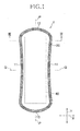
- Fig. 1 is a plan view of a pantiliner 1 as an example of the absorbent articles according to the present invention as viewed from the side of a topsheet 20
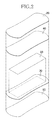
- Fig. 2 is an exploded perspective view of the pantiliner 1
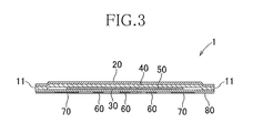
- Fig. 3 is a sectional view taken along line III-III in Fig. 1
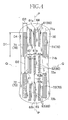
- Fig. 4 is a plan view of the pantiliner 1 as viewed from the side of a backsheet 30 thereof.
- Fig. 4 illustrates adhesive zones in an exposed state after a release sheet 80 has been peeled off.
- the pantiliner 1 has a longitudinal direction Y, a transverse direction X being orthogonal to the longitudinal direction Y, an imaginary longitudinal center line P-P bisecting a dimension in the transverse direction X and an imaginary transverse center line Q-Q bisecting a dimension in the longitudinal direction Y.
- Both side edges 11 extending in the longitudinal direction Y are curved inwardly in such a manner that a spacing between these side edges 11 gradually decreases as these side edges 11 come closer to the imaginary transverse center line Q-Q.
- Front and rear ends 12, 13 extending in the transverse direction X are curved in such a manner that a spacing between these both ends 12, 13 gradually increases, namely, the respective ends 12, 13 become convex outwardly as these both ends 12, 13 come closer to the imaginary longitudinal center line P-P.
- the pantiliner 1 includes the topsheet 20 adapted to extend on the wearer's body side, the backsheet 30 adapted to extend on the non-body-side opposite to the wearer's body side (the side of the wearer's undergarment), a bodily fluid absorbent body 40 interposed between the top- and backsheets 20, 30 and a leakage-barrier sheet 50 interposed between the backsheet 30 and the absorbent body 40.
- a fibrous nonwoven fabric more specifically, a spunlace fibrous nonwoven fabric having a mass per unit area in a range of about 30 to about 40 g/m 2 may be used.
- the topsheet 20 is liquid-permeable but the backsheet 30 is coated on its non-body-side with a water-disintegrable resin so that the material strength thereof may be improved and at the same time the liquid-permeability may be inhibited.
- a water-disintegrable resin for example, "AQ55S" (trade name) of Eastman Chemical Co. may be used.
- the fibrous nonwoven fabric from which the top- and backsheets 20, 30 are formed has water-disintegrable property.
- water-disintegrable fibrous nonwoven fabric means the fibrous nonwoven fabric formed of mechanically entangled fibers each having a fiber length of 7 mm or less and adapted to be rapidly disintegrated from the mechanically entangled state in flushing water of the lavatory.
- a piping system should not be clogged if the top- and backsheets 20, 30 are disposed into the lavatory.
- the fiber length of component fibers of the backsheet 30 is measured in conformity with JIS L 1015 8. 4. 1: Testing method for chemical fiber staple. Specifically, the pantiliner is immersed in toluene to elute an adhesive agent with which the respective sheets have been joined to one another, then the backsheet 30 is taken out and the fibers of this sheet are disentangled. To disentangle the fibers, the backsheet 30 is transferred together with 300 ml of water into a 300 ml beaker and shaken at 600 +/- 10 rpm with use of a magnetic stirrer.
- the backsheet 30 is transferred together with 1200 ml of water into a 2000 ml wide-mouth jar and shaken at 270 +/- 20 rpm with use of an appropriate shaker.
- the fiber length of the disintegrated fibers is measured by the method specified in the above-mentioned JIS. From the measured values, an average value +/- standard variation is calculated as the fiber length in the backsheet 30.
- At least the constituent fibers of the backsheet 30 have an orientation extending in the longitudinal direction Y.
- the expression that the fibers have the orientation extending in the longitudinal direction Y means that a breaking strength in the transverse direction X is 75% or less of a breaking strength in the longitudinal direction Y.
- the orientation was measured according to the method described below.
- Pieces each having a length dimension of 150 mm in the longitudinal direction Y and a length dimension of 25 mm in the transverse direction X were cut off the backsheet 30 to obtain longitudinal test pieces.
- pieces each having a length dimension of 25 mm in the longitudinal direction Y and a length dimension of 150 mm were cut off the backsheet 30 to obtain transverse test pieces.
- Measurement of breaking strength was conducted on these longitudinal test pieces and transverse test pieces.
- Tensile Tester manufactured by Instron Co. Ltd.
- a spacing between a pair of grippers of the tester was set to 100 mm, with both ends in the longitudinal direction of the test piece gripped by the gripper, the test piece was pulled at a rate of 100 mm/min and the maximum tensile strength at the break point was measured.
- the measurement was conducted under WET condition wherein the measurement was made after the test piece had been immersed in water and under DRY condition wherein the measurement was made without immersing the test piece in water.
- the orientation value was calculated according to the following formula: Maximum strength of transverse test piece / maximum strength of longitudinal test piece ⁇ 100
- the orientation measured under WET condition was 29% and the orientation measured under DRY condition was 36%, both values verifying that the test pieces have the orientation in the longitudinal direction.
- the absorbent body 40 is the same to the top- and backsheets 20, 30 in shape as well as in size and may be formed of airlaid pulp having a mass per unit area in a range of about 60 to about 80 g/m 2 . specifically, fluff wood pulp may be integrated together with the use of a spray binder to form the absorbent body 40.
- the absorbent body 40 formed in this manner is water-disintegrable and the integrated fluff wood pulp is broken up in flushing water of the lavatory without clogging the piping system.
- the leakage-barrier sheet 50 is liquid-impermeable and, specifically, water-disintegrable tissue paper having a mass per unit area in a range of about 10 to about 20 g/m 2 and laminated with the use of polylactic acidmaybe used as the leakage-barrier sheet 50.
- the leakage-barrier sheet 50 has an area smaller than those of the top- and backsheets 20, 30 and the absorbent body 40 and has a substantially rectangular shape.
- the polylactic acid becomes low-molecular in the presence of water and, in consequence, the leakage-barrier sheet 50 as a whole is sufficiently water-disintegrable to be broken up in flushing water of the lavatory without clogging the piping system.
- securing means such as a hot melt adhesive is distributed between the topsheet 20 and the absorbent body 40, between the absorbent body 40 and the leakage-barrier sheet 50 and between the leakage-barrier sheet 50 and the backsheet 30, respectively, to join them to each other.
- securing means such as a hot melt adhesive is distributed between the topsheet 20 and the absorbent body 40, between the absorbent body 40 and the leakage-barrier sheet 50 and between the leakage-barrier sheet 50 and the backsheet 30, respectively, to join them to each other.
- the backsheet 30 is disposed on the non-body-side with adhesive regions in which the backsheet 30 may be attached to the wearer's garment such as undergarment.
- the adhesive regions include first adhesive regions 60 allocated adjacent to the imaginary longitudinal center line P-P as viewed in the transverse direction X and second adhesive regions 70 allocated on both sides of the first adhesive regions 60 so as to be spaced apart from the first adhesive regions 60 as viewed in the transverse direction X.
- a hot melt adhesive may be used.
- a water-insoluble adhesive such as a rubber-based hot melt adhesive and an olefin-based hot melt adhesive is used.
- the use of a water-soluble adhesive is not excluded and both types of adhesive may be selectively used.
- the first adhesive regions 60 include front first adhesive regions 61, rear first adhesive regions 63 and central first adhesive regions 62 wherein two or more adhesive regions are arranged in the transverse direction X in each of the respective rows.
- three adhesive regions are arranged in the transverse direction X in the respective adhesive regions 61, 62, 63, and the middle adhesive regions in the respective rows are allocated on the imaginary longitudinal center line P-P.
- the front first adhesive regions 61 have front end edges 61a and rear end edges 61b aligned in the transverse direction X, respectively.
- the central first adhesive regions 62 also have front end edges 62a and rear end edges 62b aligned in the transverse direction X, respectively.
- the rear first adhesive regions 63 have front end edges 63a and rear end edges 63b aligned in the transverse direction X, respectively.
- a length dimension d1 in the longitudinal direction Y of the first adhesive region 60 is longer than the fiber length in the fibrous nonwoven fabric used as the backsheet 30 and shorter than 50.0 mm.
- the length dimension d1 is about 30.0 mm in the present embodiment.
- a spacing dimension d2 in the longitudinal direction Y between two rows of the first adhesive regions 60 being adjacent to each other in the longitudinal direction Y is in a range of about 5.0 to about 50.0 mm and preferably longer than the fiber length of the fibrous nonwoven fabric used as the backsheet 30.
- the spacing dimension d2 is about 17.6 mm in the present embodiment.
- a width dimension d3 in the transverse direction X of the first adhesive region 60 is about 3.0 mm and a spacing dimension d4 in the transverse direction X between the first adhesive regions 50 being adjacent to each other in the transverse direction X is in a range of about 3.0 to 10.0 mm and preferably shorter than the fiber length of the fibrous nonwoven fabric used as the backsheet 30.
- the spacing dimension d4 is about 5.0 mm in the present embodiment.
- the second adhesive region 70 includes front second adhesive regions 71 and rear second adhesive regions 72.
- two pairs of the front and rear second adhesive regions 71, 72 are spaced apart from each other in the longitudinal direction Y and allocated on straight lines extending substantially in parallel to the imaginary longitudinal center line P-P.
- a length dimension D1 in the longitudinal direction Y of the front and rear second adhesive regions 71, 72 is longer than the fiber length of the fibrous nonwoven fabric used as the backsheet 30 and shorter than 50.0 mm. This length dimension D1 is about 43.0 mm in the present embodiment.
- a spacing dimension D2 in the longitudinal direction Y between the front and rear adhesive regions 71, 72 is in a range of about 5.0 to about 50.0 mm and preferably longer than the fiber length of the fibrous nonwoven fabric used as the backsheet 30 This spacing dimension is about 28.6 mm in the present embodiment.
- a width dimension D3 in the transverse direction X of the respective adhesive regions 71, 72 is in a range of about 2.0 to 15.0 mm. In the present embodiment, this width dimension D3 is about 7.0 mm.
- a spacing dimension D4 in the transverse direction X between the first adhesive region 60 and the adjacent second adhesive region 70 is in a range of about 3.0 to about 10.0 mm and preferably shorter than the fiber length of the fibrous nonwoven fabric used as the backsheet 30. Such spacing dimension D4 is about 5.0 mm in the present embodiment.
- the central first adhesive regions 62 are formed in a space area defined between the front second adhesive regions 71 and the rear second adhesive regions 72 so as be allocated nearer to the imaginary longitudinal center line than the front and rear second adhesive regions 71,72 as viewed in the transverse direction X. More specifically, the central first adhesive regions 62 are allocated between an imaginary line extending so as to flush with respective rear end edges 71b of the front second adhesive regions 71 in parallel to the imaginary transverse center line Q-Q and an imaginary line extending so as to flush with respective front end edges 72a of the rear second adhesive regions 72.
- the central first adhesive regions 62 may be selectively dimensioned so as to intersect with these imaginary lines or so as not to intersect with these imaginary lines.
- the front end edges 62a of the central first adhesive regions 62 are aligned in the transverse direction X with the rear end edges 71b of the front second adhesive regions 71 and the rear end edges 62b of the central first adhesive regions 62 are aligned in the transverse direction X with the front end edges 72a of the rear second adhesive regions 72.
- the imaginary line extending in parallel to the imaginary transverse center line Q-Q and collinearly with the front end edges 62a extends so as to be collinear with the rear end edges 71b of the front second adhesive regions 71.
- the imaginary line extending in parallel to the imaginary transverse center line Q-Q and collinearly with the rear end edges 62b extends so as to be collinear also with the front end edges 72a of the rear second adhesive regions 72.
- the front end edges 61a are positioned outboard of the front end edges 71a of the front second adhesive regions 71 as viewed in the longitudinal direction Y and the rear end edges 61b are out of alignment with the 71a of the front second adhesive regions 71 in the transverse direction X.
- the imaginary line extending collinearly with the rear end edges 61b and in parallel to the imaginary transverse center line Q-Q intersects with these front second adhesive regions 71.
- the rear end edges 63b of the rear first adhesive regions 63 are positioned outboard of the rear end edges 72b of the rear second adhesive regions 72 as viewed in the longitudinal direction Y.
- the imaginary line extending collinearly with the front end edges 63a and extending in parallel to the imaginary transverse center line Q-Q intersects with these rear second adhesive regions 72.
- front and rear non-adhesive regions 64, 65 are formed.
- the front non-adhesive region 64 is formed to be longer in the longitudinal direction Y than the rear non-adhesive region 65 so as to assure an area larger than an area of the rear non-adhesive region 65.
- the first and second adhesive regions 60, 70 as described above are covered with the release sheet 80 of the same shape and size as the top- and backsheets 20, 30. By peeling the release sheet 80 off the first and second adhesive regions 60, 70, these first and second adhesive regions 60, 70 may be exposed without deteriorating adhesive force thereof.
- the pantiliner 1 may be attached to the wearer's undergarment through the intermediary of the exposed first and second adhesive regions 60, 70.
- the front and rear non-adhesive regions 64, 65 from which the release sheet 80 may be easily peeled off.
- the front non-adhesive region 64 has its area larger than the area of the rear non-adhesive region 65 and facilitates the release sheet 80 to be pinched with the wearer's fingers to peel off this.
- the central first adhesive regions 62 are allocated in the space area defined between the front and rear second adhesive regions 71, 72 and, in consequence, the pantiliner 1 attached to the wearer's undergarments might rise up from the undergarment. Assuming that none of the central first adhesive regions 62 is formed in the space area defined between the front and rear second adhesive regions and this space area remains non-adhesive to the wearer's undergarment, this space area will rise up from the wearer's undergarments until this space area will be put in contact with the wearer's body, eventually causing skin problems such as eczema. Generally, the pantiliner 1 is liable to rise up adjacent to the imaginary transverse center line Q-Q and, in view of this, it is desirable to form the adhesive region at least adjacent to the imaginary transverse centerline Q-Q.
- the second adhesive regions 70 allocated on the outer sides of the first adhesive regions 60 in the transverse direction X are dimensioned to be relatively large in the longitudinal direction Y as well as in the transverse direction X to improve the adhesive force to the wearer's undergarment, thereby preventing the pantiliner 1 from being peeled off and curled along the lateral edges 11.
- the pantiliner 1 as described above is composed of the top-and backsheets 20, 30, the absorbent body 40 and the leakage-barrier sheet 50 all having a sufficient degree of water-disintegrable property to be thrown away into the lavatory after used.
- the used pantiliner 1 thrown into the lavatory is finely disintegrated in flushing water of the lavatory and the piping system of the lavatory should not be clogged.
- the backsheet 30 includes the first and second adhesive regions 60, 70 formed thereon and these adhesive regions are not easily disintegrated in flushing water. In consequence, the portions of the backsheet 30 provided with these adhesive regions 60, 70 are also not easily disintegrated. However, these adhesive regions 60, 70 are formed so as to be spaced apart from each other in the longitudinal direction Y as well as in the transverse direction X and the backsheet 30 should not stay as a chunk in the piping system.
- the dimension in the longitudinal direction Y of the first and second adhesive regions 60, 70 is longer than the fiber length of the backsheet 30 and shorter than 50 mm and consequently the fragments of the backsheet 30 respectively including the adhesive regions 60, 70 are sufficiently small to flow smoothly through the piping system even when these fragments of the backsheet 30 including the adhesive regions are not finely disintegrated in flushing water. Assuming that the dimension in the longitudinal direction Y of the first and second adhesive regions 60, 70 exceeds 50 mm, the fragments of the backsheet 30 respectively including the adhesive regions 60, 70 relatively long in the longitudinal direction Y might remain not disintegrated and these fragments might be entangled with each other to form a chunk causing clogging of the piping system.
- the dimension as described above is shorter than the fiber length of the backsheet 30, some of the fibers underlying the first and second adhesive regions 60, 70 of the backsheet 30 might dissociate from the backsheet 30 and attached to the wearer's undergarment together with the adhesive agent.
- the first and second adhesive regions 60, 70 may be dimensioned to be longer than the fiber length in the first and second adhesive regions 60, 70 to resolve such inconvenience, and to assure the pantiliner 1 to be attached to the wearer's undergarment.
- by orienting the component fibers of the backsheet 30 in the longitudinal direction Y and forming the first and second adhesive regions 60, 70 so as to extend in the longitudinal direction Y it is possible to inhibit the undesirable dissociation of the fibers more reliably.
- the spacing dimension d2 in the longitudinal direction Y between two rows of the first adhesive regions 60 being adjacent to each other in the longitudinal direction Y and the spacing dimension D2 in the longitudinal direction Y between the front and rear adhesive regions 71, 72 are preferably larger than the fiber length of the component fibers in the fibrous nonwoven fabric used as the backsheet 30.
- the spacing dimension d4 in the transverse direction X between each pair of the adjacent first adhesive regions 60 and the spacing dimension D4 in the transverse direction X between each pair of the adjacent second adhesive region 70 and the first adhesive region 60 are preferably smaller than the fiber length of component fibers in the fibrous nonwoven fabric used as the backsheet 30.
- the component fibers are oriented in the longitudinal direction Y and it is unnecessary to widen the spacing dimensions d4 and D4 so as to be larger than the length dimension of the fiber length in the backsheet 30.
- a spacing dimension between the rear end edge 71b and the associated front end edge 62 is preferably in a range of about 1.0 to about 5.0 mm.
- the central first adhesive regions 62 are allocated in the space area defined between the front second adhesive regions 71 and the rear second adhesive regions 72 and whereby it is possible to prevent the space area defined between these front and rear second adhesive regions 71, 72 from rising up above the wearer's undergarment.
- the respective dimensions may be selectively determined so long as such advantageous effect is ensured.
- the first adhesive region 60 includes a plurality of adhesive regions arranged in the transverse direction X and the second adhesive region 70 includes two adhesive regions allocated outboard in the transverse direction X of the front and rear first adhesive regions.
- each of the second adhesive regions 70 is formed so as to have its dimension in the transverse direction X larger than that of the first adhesive regions 60 and whereby the pantiliner 1 may be reliably attached to the wearer's undergarment.
- a plurality of the first adhesive regions 60 and a plurality of the second adhesive regions 70 are arranged in the transverse direction X so as to be spaced apart from each other and whereby the water-disintegrable property may be reliably maintained.
- the number and the dimension of the first adhesive regions 60 in the longitudinal direction Y and in the transverse direction X as well as the number and the dimension of the second adhesive regions 70 in the longitudinal direction Y and in the transverse direction X are not limited to those in the embodiment described hereinbefore but may be appropriately selected.
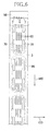
- Fig. 5 is a schematic diagram illustrating the method for producing the pantiliner 1.
- Fig. 6 is a diagram illustrating a step in which the first and second adhesive regions 60, 70 are formed and schematically illustrating a coater 98 so that a positional relation between nozzles and adhesive regions may be understood.
- a first fibrous web 2 to form the topsheet 20 is transported via a first roller 91 in a machine direction MD.
- An absorbent web 4 to form the absorbent body 40 is transported via a second roller 92 in the machine direction MD.
- the absorbent web 4 is coated by a coater 93 with a hot melt adhesive and laminated on the first web 2 and secured thereto.
- a coater 94 distributes hot melt adhesive onto a surface of the absorbent web 4 opposite to its surface being in face-to-face relationship with the first fibrous web 2.
- a leakage-barrier film 5 as material of the leakage-barrier sheet 50 is transported via a third roller 95 in the machine direction MD, laminated on the absorbent web 4 and bonded thereto. In this regard, the leakage-barrier film 5 is preliminarily cut in the machine direction MD and then transported via the third roller 95 to the absorbent web 4.
- a coater 96 distributes a hot melt adhesive to a surface of the leakage-barrier film 5 opposite to its surface being in face-to-face relationship with the absorbent web 4.
- a second fibrous web 3 as material for the backsheet 30 is transported via a fourth roller 97 in the machine direction and MD and laminated on the leakage-barrier film 5 through the intermediary of hot melt adhesive and bonded thereto.
- the hot melt adhesive distributed by the coaters 93, 94, 96 is, for example, evenly distributed substantially over the entire area of the respective webs or the film by spray coating.
- a coater 98 distribute a hot melt adhesive to a surface of the second fibrous web 3 opposite to its surface in face-to-face relationship with the leakage-barrier film 5 to form the first and second adhesive regions 60, 70.
- the coater 98 has first nozzles 6 serving to form the first adhesive region 60 and second nozzles 7 lying on both outsides of the first nozzles 6 as viewed in a cross direction CD being orthogonal to the machine direction MD. This means that the same coater is provided with the first nozzles 6 and the second nozzles 7.
- the hot melt adhesive distributed from these first and second nozzles 6, 7 make it possible to form linear and continuous adhesive regions.
- a dimension in the CD direction of the discharge opening of the second nozzles 7 is larger than that of the first nozzles 6.
- the hot melt adhesive discharge timings of the first nozzles 6 and the second nozzles 7 separately controlled by separately prepared programs to form the first and second adhesive regions 60, 70 having different dimensions in the longitudinal direction Y as well as in the transverse direction.
- the first and second adhesive regions 60, 70 can be formed at once with no loss of production time.
- the release web 8 as material for the release sheet 80 is laminated on the second fibrous web 3 which was provided with the first and second adhesive regions 60, 70 by the coater 98.
- the release web 8 is bonded to the second fibrous web 3 through the intermediary of the first and second adhesive regions 60, 70.
- Such laminate web is cut by a cutter (not shown) along an imaginary line 99 indicated in Fig. 6 to form the individual pantiliners 1.
- the laminate web as described above is formed in a manner that the first and second adhesive regions 60, 70 do not overlap the imaginary line 99. In consequence, it is possible to prevent adhesive agent of the first and second adhesive regions 60, 70 from adhering to the cutter blade.
- the continuous laminate may be cut in this manner to form a large amount of the pantiliners 1 in a small amount of time.
- the present invention includes first and second aspects.
- An absorbent article 1 has a longitudinal direction Y and a transverse direction X and includes a body-side, non-body-side opposite to the body-side, a water-disintegrable topsheet 20 lying on the body-side, a water-disintegrable backsheet 30 lying on the non-body-side, a water-disintegrable absorbent body 40 interposed between these top- and backsheets 20, 30 and adhesive regions 60, 70 formed on the non-body-side of the backsheet 30 and through which the backsheet 30 is attachable to a wearer's undergarment.
- the backsheet 30 is formed of a fibrous nonwoven fabric of which component fibers have an orientation extending in the longitudinal direction Y.
- the adhesive regions include first adhesive regions 60 extending in the longitudinal direction Y and second adhesive regions 70 allocated on both outer sides in the transverse direction X of the first adhesive regions 60 so as to be spaced apart from the first adhesive regions 60 in the transverse direction X. At least a part of the first adhesive regions 60 is allocated in a space area defined in the longitudinal direction between the second adhesive regions 70.
- the first aspect may include at least following embodiments.
- the second aspect relates to improvement in a method of producing the absorbent article as described above.
- a method for producing the absorbent article including the steps of: transporting first fibrous web in a machine direction MD; laminating an absorbent web 4 on the first fibrous web 2 and securing them to each other; laminating second fibrous web 3 on the first fibrous web 2 through the absorbent web 4 and securing them to each other; forming adhesive regions on a surface of one of the first fibrous web 2 and the second fibrous web 3 opposite to the absorbent web 4; and laminating a release sheet 8 on the adhesive regions 60, 70 and cutting a laminate composed of the first and second fibrous webs 2, 3, the absorbent web 4 and the release sheet 8.
- the second invention lies in that an adhesive coater 98 having first nozzles 6 arranged in the cross direction being orthogonal to the machine direction MD and second nozzles 7 allocated outboard in the cross direction CD of the first nozzles distribute adhesive agent and thereby forms the adhesive regions 60, 70.
- the second invention may include at least an embodiment as described below.
- the laminate may be cut between each pair of the adjacent adhesive regions 60, 70 arranged in the longitudinal direction Y so as to be spaced apart from each other.
- the respective constituent elements of the pantiliner 1 as an example of the absorbent articles are not limited to those described in this description but other various types of material widely used in the relevant technical field may be used without limitation.
- the terms “first”, “second”, “third” and “fourth” used in the description of the present invention are used merely to distinguish the similar elements or similar positions.
Landscapes
- Health & Medical Sciences (AREA)
- Epidemiology (AREA)
- Engineering & Computer Science (AREA)
- Biomedical Technology (AREA)
- Heart & Thoracic Surgery (AREA)
- Vascular Medicine (AREA)
- Life Sciences & Earth Sciences (AREA)
- Animal Behavior & Ethology (AREA)
- General Health & Medical Sciences (AREA)
- Public Health (AREA)
- Veterinary Medicine (AREA)
- Manufacturing & Machinery (AREA)
- Absorbent Articles And Supports Therefor (AREA)
Abstract
Description
- The present invention relates to absorbent articles and methods for producing the same and more specifically to water-disintegrable sanitary napkins, pantiliners and urine-absorbent pads and methods for producing the same.
- Conventionally, sanitary napkins or pantiliners as examples of the water-disintegrable absorbent articles are known. For example, patent literature 1 discloses the absorbent article having a topsheet, a backsheet and an absorbent layer interposed between the top- and backsheets. As material for the topsheet and the backsheet, water-disintegrable fibrous nonwoven fabric is used in this known absorbent article. On the lower surface of the backsheet, pressure-sensitive adhesive regions are formed. This absorbent article as a whole is water-disintegrable and piping system should not be clogged after the used article has been disposed into flushing water of a lavatory.
- {PTL 1}:
JP 3748022 B - In the absorbent article disclosed in PTL 1, a plurality of the adhesive regions is formed so as to be spaced apart from each other in the longitudinal direction as well as in the transverse direction. Each of these adhesive regions has a circular shape of which the diameter is in a range of 10 mm to 1 mm. Such small adhesive regions have weak adhesive strength and, to compensate this, pressure-sensitive adhesive agent of high adhesive strength should be used. As a result, the backsheet of such absorbent article is attached to the wearer's undergarment too tightly and, when the wearer tries to peel off the article from the undergarment after used, the component fibers in the fibrous nonwoven fabric as material for the backsheet might dissociate from the backsheet and left on the undergarment together with the pressure-sensitive adhesive agent.
- An object of the present invention is to provide an absorbent article improved to be easily peeled off the wearer's undergarment after used.
- The present invention includes first and second aspects.
- The first aspect relates to an absorbent article having a longitudinal direction and a transverse direction and including a body-side, a non-body-side opposite to the body-side, a water-disintegrable topsheet lying on the body-side, a water-disintegrable backsheet lying on the non-body-side, a water-disintegrable body-fluid absorbent body interposed between these top- and backsheets, and adhesive regions formed on the non-body-side of the backsheet and through which the backsheet is attachable to a wearer's undergarment.
- In the absorbent article, the backsheet is formed of a fibrous nonwoven fabric of which component fibers have an orientation extending in the longitudinal direction, the adhesive regions include first adhesive regions extending in the longitudinal direction and second adhesive regions allocated on both outer sides in the transverse direction of the first adhesive regions so as to be spaced apart from the first adhesive regions in the transverse direction and at least part of the first adhesive regions is allocated in a space area defined in the longitudinal direction between the second adhesive regions.
- As used herein, the expression "the absorbent article is attachable to the wearer's undergarment" means that the absorbent article may be attached to the wearer's undergarment through the adhesive regions and, after used, the article may be peeled off the wearer's undergarment. It is suggested by this expression that adhesive strength may be at a level allowing the article once attached to the wearer's undergarment to be easily peeled off the wearer's undergarment after used. For the adhesive regions, a pressure-sensitive adhesive agent may be used.
- The second aspect relates to a method of producing the absorbent article as described above. Namely, a method for producing the absorbent article including the steps of: transporting a first fibrous web in a machine direction; laminating an absorbent web on the first fibrous web and securing them to each other; laminating a second fibrous web on the first fibrous web through the absorbent web and securing them to each other; forming adhesive regions on a surface of one of the first fibrous web and the second fibrous web opposite to the absorbent web; laminating a release sheet on the adhesive regions; and cutting a laminate composed of the first and second fibrous webs, the absorbent web and the release sheet.
- In the method for producing the absorbent article, an adhesive coater having first nozzles arranged in the cross direction being orthogonal to the machine direction and second nozzles allocated on the both outsides in the cross direction of the first nozzles distributes an adhesive agent at some intervals and thereby forms the adhesive regions.
- As used herein, the term "water-disintegrable sheet" means a fibrous nonwoven fabric sheet formed of component fibers having a fiber length of 7 mm or less and oriented so that a mechanical entanglement of the fibers may be broken up in flushing water of the lavatory.
- According to one or more embodiments of the present invention, since the first and second adhesive regions are formed on the backsheet so as to extend in the longitudinal direction, some of the fibers underlying the first and second adhesive regions of the backsheet should not dissociate from the backsheet and adhered to the wearer's undergarment together with the adhesive agent. The arrangement that the first adhesive regions are allocated also in the space area defined by the second adhesive regions spaced apart from each other in the longitudinal direction is effective to prevent the portions of the backsheet including the first and second adhesive regions from being entangled with each other and forming a chunk possibly causing the piping system to become clogged.
-
- {
Fig. 1} Fig. 1 is a plan view of a pantiliner as an embodiment of the absorbent articles. - {
Fig. 2} Fig. 2 is an exploded perspective view of the pantiliner. - {
Fig. 3} Fig. 3 is a sectional view taken along line III-III inFig. 1 . - {
Fig. 4} Fig. 4 is a plan view of the pantiliner as viewed from the side of a backsheet thereof. - {
Fig. 5} Fig. 5 is a schematic diagram illustrating a production process for the absorbent article. - {
Fig. 6} Fig. 6 is a diagram illustrating a process of forming adhesive zones. -
Fig. 1 is a plan view of a pantiliner 1 as an example of the absorbent articles according to the present invention as viewed from the side of atopsheet 20,Fig. 2 is an exploded perspective view of the pantiliner 1,Fig. 3 is a sectional view taken along line III-III inFig. 1 andFig. 4 is a plan view of the pantiliner 1 as viewed from the side of abacksheet 30 thereof. For convenience of illustration,Fig. 4 illustrates adhesive zones in an exposed state after arelease sheet 80 has been peeled off. - As illustrated in
Figs. 1 through 4 , the pantiliner 1 has a longitudinal direction Y, a transverse direction X being orthogonal to the longitudinal direction Y, an imaginary longitudinal center line P-P bisecting a dimension in the transverse direction X and an imaginary transverse center line Q-Q bisecting a dimension in the longitudinal direction Y. Bothside edges 11 extending in the longitudinal direction Y are curved inwardly in such a manner that a spacing between theseside edges 11 gradually decreases as theseside edges 11 come closer to the imaginary transverse center line Q-Q. Front andrear ends 12, 13 extending in the transverse direction X are curved in such a manner that a spacing between these bothends 12, 13 gradually increases, namely, therespective ends 12, 13 become convex outwardly as these bothends 12, 13 come closer to the imaginary longitudinal center line P-P. - The pantiliner 1 includes the
topsheet 20 adapted to extend on the wearer's body side, thebacksheet 30 adapted to extend on the non-body-side opposite to the wearer's body side (the side of the wearer's undergarment), a bodily fluidabsorbent body 40 interposed between the top- andbacksheets barrier sheet 50 interposed between thebacksheet 30 and theabsorbent body 40. As material for the top- andbacksheets topsheet 20 is liquid-permeable but thebacksheet 30 is coated on its non-body-side with a water-disintegrable resin so that the material strength thereof may be improved and at the same time the liquid-permeability may be inhibited. As such a water-disintegrable resin, for example, "AQ55S" (trade name) of Eastman Chemical Co. may be used. - The fibrous nonwoven fabric from which the top- and
backsheets backsheets - The fiber length of component fibers of the
backsheet 30 is measured in conformity with JIS L 1015 8. 4. 1: Testing method for chemical fiber staple. Specifically, the pantiliner is immersed in toluene to elute an adhesive agent with which the respective sheets have been joined to one another, then thebacksheet 30 is taken out and the fibers of this sheet are disentangled. To disentangle the fibers, thebacksheet 30 is transferred together with 300 ml of water into a 300 ml beaker and shaken at 600 +/- 10 rpm with use of a magnetic stirrer. Alternatively, thebacksheet 30 is transferred together with 1200 ml of water into a 2000 ml wide-mouth jar and shaken at 270 +/- 20 rpm with use of an appropriate shaker. The fiber length of the disintegrated fibers is measured by the method specified in the above-mentioned JIS. From the measured values, an average value +/- standard variation is calculated as the fiber length in thebacksheet 30. - At least the constituent fibers of the
backsheet 30 have an orientation extending in the longitudinal direction Y. The expression that the fibers have the orientation extending in the longitudinal direction Y means that a breaking strength in the transverse direction X is 75% or less of a breaking strength in the longitudinal direction Y. The orientation was measured according to the method described below. - Pieces each having a length dimension of 150 mm in the longitudinal direction Y and a length dimension of 25 mm in the transverse direction X were cut off the
backsheet 30 to obtain longitudinal test pieces. In the same manner, pieces each having a length dimension of 25 mm in the longitudinal direction Y and a length dimension of 150 mm were cut off thebacksheet 30 to obtain transverse test pieces. Measurement of breaking strength was conducted on these longitudinal test pieces and transverse test pieces. For the measurement, Tensile Tester (manufactured by Instron Co. Ltd.) was used. For the longitudinal pieces and the transverse test pieces, a spacing between a pair of grippers of the tester was set to 100 mm, with both ends in the longitudinal direction of the test piece gripped by the gripper, the test piece was pulled at a rate of 100 mm/min and the maximum tensile strength at the break point was measured. The measurement was conducted under WET condition wherein the measurement was made after the test piece had been immersed in water and under DRY condition wherein the measurement was made without immersing the test piece in water. The orientation value was calculated according to the following formula:
- According to this embodiment, the orientation measured under WET condition was 29% and the orientation measured under DRY condition was 36%, both values verifying that the test pieces have the orientation in the longitudinal direction.
- The
absorbent body 40 is the same to the top- andbacksheets absorbent body 40. Theabsorbent body 40 formed in this manner is water-disintegrable and the integrated fluff wood pulp is broken up in flushing water of the lavatory without clogging the piping system. - The leakage-
barrier sheet 50 is liquid-impermeable and, specifically, water-disintegrable tissue paper having a mass per unit area in a range of about 10 to about 20 g/m2 and laminated with the use of polylactic acidmaybe used as the leakage-barrier sheet 50. The leakage-barrier sheet 50 has an area smaller than those of the top- andbacksheets absorbent body 40 and has a substantially rectangular shape. The polylactic acid becomes low-molecular in the presence of water and, in consequence, the leakage-barrier sheet 50 as a whole is sufficiently water-disintegrable to be broken up in flushing water of the lavatory without clogging the piping system. - Though not illustrated, securing means such as a hot melt adhesive is distributed between the
topsheet 20 and theabsorbent body 40, between theabsorbent body 40 and the leakage-barrier sheet 50 and between the leakage-barrier sheet 50 and thebacksheet 30, respectively, to join them to each other. Along the inside of the both side edges 11 and the front and rear end edges 12, 13 of the pantiliner 1, thetopsheet 20, theabsorbent body 40 and thebacksheet 30 are heated under a pressure to seal them together. - Referring to
Fig. 4 , thebacksheet 30 is disposed on the non-body-side with adhesive regions in which thebacksheet 30 may be attached to the wearer's garment such as undergarment. The adhesive regions include firstadhesive regions 60 allocated adjacent to the imaginary longitudinal center line P-P as viewed in the transverse direction X and secondadhesive regions 70 allocated on both sides of the firstadhesive regions 60 so as to be spaced apart from the firstadhesive regions 60 as viewed in the transverse direction X. To be disposed with the first and secondadhesive regions - The first
adhesive regions 60 include front firstadhesive regions 61, rear firstadhesive regions 63 and central firstadhesive regions 62 wherein two or more adhesive regions are arranged in the transverse direction X in each of the respective rows. In the present embodiment, three adhesive regions are arranged in the transverse direction X in the respectiveadhesive regions adhesive regions 61 have front end edges 61a and rear end edges 61b aligned in the transverse direction X, respectively. The central firstadhesive regions 62 also have front end edges 62a and rear end edges 62b aligned in the transverse direction X, respectively. In the same manner, the rear firstadhesive regions 63 have front end edges 63a and rear end edges 63b aligned in the transverse direction X, respectively. - A length dimension d1 in the longitudinal direction Y of the first
adhesive region 60 is longer than the fiber length in the fibrous nonwoven fabric used as thebacksheet 30 and shorter than 50.0 mm. The length dimension d1 is about 30.0 mm in the present embodiment. A spacing dimension d2 in the longitudinal direction Y between two rows of the firstadhesive regions 60 being adjacent to each other in the longitudinal direction Y is in a range of about 5.0 to about 50.0 mm and preferably longer than the fiber length of the fibrous nonwoven fabric used as thebacksheet 30. The spacing dimension d2 is about 17.6 mm in the present embodiment. A width dimension d3 in the transverse direction X of the firstadhesive region 60 is about 3.0 mm and a spacing dimension d4 in the transverse direction X between the firstadhesive regions 50 being adjacent to each other in the transverse direction X is in a range of about 3.0 to 10.0 mm and preferably shorter than the fiber length of the fibrous nonwoven fabric used as thebacksheet 30. The spacing dimension d4 is about 5.0 mm in the present embodiment. - The second
adhesive region 70 includes front secondadhesive regions 71 and rear secondadhesive regions 72. According to the present embodiment, two pairs of the front and rear secondadhesive regions adhesive regions backsheet 30 and shorter than 50.0 mm. This length dimension D1 is about 43.0 mm in the present embodiment. A spacing dimension D2 in the longitudinal direction Y between the front and rearadhesive regions backsheet 30 This spacing dimension is about 28.6 mm in the present embodiment. A width dimension D3 in the transverse direction X of the respectiveadhesive regions adhesive region 60 and the adjacent secondadhesive region 70 is in a range of about 3.0 to about 10.0 mm and preferably shorter than the fiber length of the fibrous nonwoven fabric used as thebacksheet 30. Such spacing dimension D4 is about 5.0 mm in the present embodiment. - The central first
adhesive regions 62 are formed in a space area defined between the front secondadhesive regions 71 and the rear secondadhesive regions 72 so as be allocated nearer to the imaginary longitudinal center line than the front and rear secondadhesive regions adhesive regions 62 are allocated between an imaginary line extending so as to flush with respective rear end edges 71b of the front secondadhesive regions 71 in parallel to the imaginary transverse center line Q-Q and an imaginary line extending so as to flush with respective front end edges 72a of the rear secondadhesive regions 72. The central firstadhesive regions 62 may be selectively dimensioned so as to intersect with these imaginary lines or so as not to intersect with these imaginary lines. - According to the present embodiment, the front end edges 62a of the central first
adhesive regions 62 are aligned in the transverse direction X with the rear end edges 71b of the front secondadhesive regions 71 and the rear end edges 62b of the central firstadhesive regions 62 are aligned in the transverse direction X with the front end edges 72a of the rear secondadhesive regions 72. Specifically, the imaginary line extending in parallel to the imaginary transverse center line Q-Q and collinearly with thefront end edges 62a extends so as to be collinear with the rear end edges 71b of the front secondadhesive regions 71. The imaginary line extending in parallel to the imaginary transverse center line Q-Q and collinearly with therear end edges 62b extends so as to be collinear also with the front end edges 72a of the rear secondadhesive regions 72. In the front firstadhesive regions 61, thefront end edges 61a are positioned outboard of the front end edges 71a of the front secondadhesive regions 71 as viewed in the longitudinal direction Y and the rear end edges 61b are out of alignment with the 71a of the front secondadhesive regions 71 in the transverse direction X. In other words, the imaginary line extending collinearly with the rear end edges 61b and in parallel to the imaginary transverse center line Q-Q intersects with these front secondadhesive regions 71. In a similar fashion, the rear end edges 63b of the rear firstadhesive regions 63 are positioned outboard of the rear end edges 72b of the rear secondadhesive regions 72 as viewed in the longitudinal direction Y. In other words, the imaginary line extending collinearly with the front end edges 63a and extending in parallel to the imaginary transverse center line Q-Q intersects with these rear secondadhesive regions 72. - Outboard in the longitudinal direction Y of the front and rear first
adhesive regions non-adhesive regions non-adhesive region 64 is formed to be longer in the longitudinal direction Y than the rearnon-adhesive region 65 so as to assure an area larger than an area of the rearnon-adhesive region 65. - The first and second
adhesive regions release sheet 80 of the same shape and size as the top- andbacksheets release sheet 80 off the first and secondadhesive regions adhesive regions adhesive regions - At least outboard in the longitudinal direction Y of the first
adhesive regions 60, there are formed with the front and rearnon-adhesive regions release sheet 80 may be easily peeled off. Particularly, the frontnon-adhesive region 64 has its area larger than the area of the rearnon-adhesive region 65 and facilitates therelease sheet 80 to be pinched with the wearer's fingers to peel off this. - In the pantiliner 1 described above, the central first
adhesive regions 62 are allocated in the space area defined between the front and rear secondadhesive regions adhesive regions 62 is formed in the space area defined between the front and rear second adhesive regions and this space area remains non-adhesive to the wearer's undergarment, this space area will rise up from the wearer's undergarments until this space area will be put in contact with the wearer's body, eventually causing skin problems such as eczema. Generally, the pantiliner 1 is liable to rise up adjacent to the imaginary transverse center line Q-Q and, in view of this, it is desirable to form the adhesive region at least adjacent to the imaginary transverse centerline Q-Q. - According to the present embodiment, the second
adhesive regions 70 allocated on the outer sides of the firstadhesive regions 60 in the transverse direction X are dimensioned to be relatively large in the longitudinal direction Y as well as in the transverse direction X to improve the adhesive force to the wearer's undergarment, thereby preventing the pantiliner 1 from being peeled off and curled along the lateral edges 11. In this regard, it is also possible for the same purpose to enlarge the dimension of the secondadhesive regions 70 only in the longitudinal direction Y and the transverse direction X. - The pantiliner 1 as described above is composed of the top-and
backsheets absorbent body 40 and the leakage-barrier sheet 50 all having a sufficient degree of water-disintegrable property to be thrown away into the lavatory after used. The used pantiliner 1 thrown into the lavatory is finely disintegrated in flushing water of the lavatory and the piping system of the lavatory should not be clogged. Thebacksheet 30 includes the first and secondadhesive regions backsheet 30 provided with theseadhesive regions adhesive regions backsheet 30 should not stay as a chunk in the piping system. - The dimension in the longitudinal direction Y of the first and second
adhesive regions backsheet 30 and shorter than 50 mm and consequently the fragments of thebacksheet 30 respectively including theadhesive regions backsheet 30 including the adhesive regions are not finely disintegrated in flushing water. Assuming that the dimension in the longitudinal direction Y of the first and secondadhesive regions backsheet 30 respectively including theadhesive regions backsheet 30, some of the fibers underlying the first and secondadhesive regions backsheet 30 might dissociate from thebacksheet 30 and attached to the wearer's undergarment together with the adhesive agent. However, the first and secondadhesive regions adhesive regions backsheet 30 in the longitudinal direction Y and forming the first and secondadhesive regions - The spacing dimension d2 in the longitudinal direction Y between two rows of the first
adhesive regions 60 being adjacent to each other in the longitudinal direction Y and the spacing dimension D2 in the longitudinal direction Y between the front and rearadhesive regions backsheet 30. By dimensioning in this manner, it is assured to prevent the adhesive regions arranged in alignment with each other in the longitudinal direction Y from becoming contiguous to each other under an influence of the component fibers of the backsheet 30 oriented in the longitudinal direction Y. In this way, the adhesive regions arranged on thebacksheet 30 to be in alignment with each other in the longitudinal direction Y are easily separated from each other in the flushing water and these adhesive regions might be entangled together to form a chunk remaining in the piping system. - The spacing dimension d4 in the transverse direction X between each pair of the adjacent first
adhesive regions 60 and the spacing dimension D4 in the transverse direction X between each pair of the adjacent secondadhesive region 70 and the firstadhesive region 60 are preferably smaller than the fiber length of component fibers in the fibrous nonwoven fabric used as thebacksheet 30. In thebacksheet 30, the component fibers are oriented in the longitudinal direction Y and it is unnecessary to widen the spacing dimensions d4 and D4 so as to be larger than the length dimension of the fiber length in thebacksheet 30. Even if the spacing dimensions as described above are shorter than the fiber length of the component fibers in thebacksheet 30, it is possible to break up the continuity in the transverse direction X between each pair of the adjacent firstadhesive regions 60 or each pair of the adjacent first and secondadhesive regions adhesive regions 60 and the spacing dimension between each pair of the firstadhesive region 60 and the adjacent secondadhesive region 70, a total adhesive area on thebacksheet 30 as a whole can be enlarged and whereby an adhesive force to the wearer's undergarment may be improved. - While the respective rear end edges 71b of the front second
adhesive regions 71 are aligned with the respective front end edges 62a of the central firstadhesive regions 62 in the transverse direction X according to the present embodiment, it is also possible to arrange these adhesive regions in such a manner that the respectivefront end edges 62a are out of alignment with the respective rear end edges 71 in the longitudinal direction Y. In such a case, a spacing dimension between therear end edge 71b and the associatedfront end edge 62 is preferably in a range of about 1.0 to about 5.0 mm. In the present invention, the central firstadhesive regions 62 are allocated in the space area defined between the front secondadhesive regions 71 and the rear secondadhesive regions 72 and whereby it is possible to prevent the space area defined between these front and rear secondadhesive regions - According to this embodiment, the first
adhesive region 60 includes a plurality of adhesive regions arranged in the transverse direction X and the secondadhesive region 70 includes two adhesive regions allocated outboard in the transverse direction X of the front and rear first adhesive regions. In these adhesive regions, each of the secondadhesive regions 70 is formed so as to have its dimension in the transverse direction X larger than that of the firstadhesive regions 60 and whereby the pantiliner 1 may be reliably attached to the wearer's undergarment. In addition, a plurality of the firstadhesive regions 60 and a plurality of the secondadhesive regions 70 are arranged in the transverse direction X so as to be spaced apart from each other and whereby the water-disintegrable property may be reliably maintained. In this regard, the number and the dimension of the firstadhesive regions 60 in the longitudinal direction Y and in the transverse direction X as well as the number and the dimension of the secondadhesive regions 70 in the longitudinal direction Y and in the transverse direction X are not limited to those in the embodiment described hereinbefore but may be appropriately selected. - The pantiliner as has been described hereinabove is manufactured by a method as described hereunder with reference to the accompanying drawings.
Fig. 5 is a schematic diagram illustrating the method for producing the pantiliner 1.Fig. 6 is a diagram illustrating a step in which the first and secondadhesive regions coater 98 so that a positional relation between nozzles and adhesive regions may be understood. - Referring to
Fig. 5 , a firstfibrous web 2 to form thetopsheet 20 is transported via afirst roller 91 in a machine direction MD. An absorbent web 4 to form theabsorbent body 40 is transported via asecond roller 92 in the machine direction MD. The absorbent web 4 is coated by acoater 93 with a hot melt adhesive and laminated on thefirst web 2 and secured thereto. Acoater 94 distributes hot melt adhesive onto a surface of the absorbent web 4 opposite to its surface being in face-to-face relationship with the firstfibrous web 2. A leakage-barrier film 5 as material of the leakage-barrier sheet 50 is transported via athird roller 95 in the machine direction MD, laminated on the absorbent web 4 and bonded thereto. In this regard, the leakage-barrier film 5 is preliminarily cut in the machine direction MD and then transported via thethird roller 95 to the absorbent web 4. - A
coater 96 distributes a hot melt adhesive to a surface of the leakage-barrier film 5 opposite to its surface being in face-to-face relationship with the absorbent web 4. A secondfibrous web 3 as material for thebacksheet 30 is transported via afourth roller 97 in the machine direction and MD and laminated on the leakage-barrier film 5 through the intermediary of hot melt adhesive and bonded thereto. The hot melt adhesive distributed by thecoaters - A
coater 98 distribute a hot melt adhesive to a surface of the secondfibrous web 3 opposite to its surface in face-to-face relationship with the leakage-barrier film 5 to form the first and secondadhesive regions Fig. 6 , thecoater 98 hasfirst nozzles 6 serving to form the firstadhesive region 60 andsecond nozzles 7 lying on both outsides of thefirst nozzles 6 as viewed in a cross direction CD being orthogonal to the machine direction MD. This means that the same coater is provided with thefirst nozzles 6 and thesecond nozzles 7. The hot melt adhesive distributed from these first andsecond nozzles second nozzles 7 is larger than that of thefirst nozzles 6. The hot melt adhesive discharge timings of thefirst nozzles 6 and thesecond nozzles 7 separately controlled by separately prepared programs to form the first and secondadhesive regions adhesive regions adhesive regions - Referring again to
Fig. 5 , the release web 8 as material for therelease sheet 80 is laminated on the secondfibrous web 3 which was provided with the first and secondadhesive regions coater 98. The release web 8 is bonded to the secondfibrous web 3 through the intermediary of the first and secondadhesive regions imaginary line 99 indicated inFig. 6 to form the individual pantiliners 1. - The laminate web as described above is formed in a manner that the first and second
adhesive regions imaginary line 99. In consequence, it is possible to prevent adhesive agent of the first and secondadhesive regions - The present invention described above may be arranged in at least one or more of the following features:
- The present invention includes first and second aspects.
- The first aspect relates to an improved absorbent article as described below. An absorbent article 1 has a longitudinal direction Y and a transverse direction X and includes a body-side, non-body-side opposite to the body-side, a water-
disintegrable topsheet 20 lying on the body-side, a water-disintegrable backsheet 30 lying on the non-body-side, a water-disintegrableabsorbent body 40 interposed between these top- andbacksheets adhesive regions backsheet 30 and through which thebacksheet 30 is attachable to a wearer's undergarment. - In the absorbent article 1 according to the first aspect, the
backsheet 30 is formed of a fibrous nonwoven fabric of which component fibers have an orientation extending in the longitudinal direction Y. The adhesive regions include firstadhesive regions 60 extending in the longitudinal direction Y and secondadhesive regions 70 allocated on both outer sides in the transverse direction X of the firstadhesive regions 60 so as to be spaced apart from the firstadhesive regions 60 in the transverse direction X. At least a part of the firstadhesive regions 60 is allocated in a space area defined in the longitudinal direction between the secondadhesive regions 70. - The first aspect may include at least following embodiments.
- (1) Respective length dimensions in the longitudinal direction Y of the
adhesive regions backsheet 30. - (2) The first
adhesive regions 60 may include front firstadhesive regions 61, rear firstadhesive regions 63 and centraladhesive regions 62 allocated between the front and rearadhesive regions - (3) The second
adhesive regions 70 may have front secondadhesive regions 71 and rear secondadhesive regions 72. - (4) A width dimension in the transverse direction X of the first and second
adhesive regions - (5) A space dimension in the longitudinal direction Y between the first and second
adhesive regions - (6) A space dimension in the transverse direction X between the first and second
adhesive regions - (7) A length dimension in the longitudinal direction Y of the second
adhesive regions 70 may be longer than a length dimension in the longitudinal dimension of the firstadhesive regions 60. - (8)
Non-adhesive regions adhesive regions 60. - (9) A liquid-impermeable leakage-
barrier sheet 50 may be interposed between theabsorbent body 40 and thebacksheet 30 and at least one of the first and secondadhesive regions barrier sheet 50. - The second aspect relates to improvement in a method of producing the absorbent article as described above. Namely, a method for producing the absorbent article including the steps of: transporting first fibrous web in a machine direction MD; laminating an absorbent web 4 on the first
fibrous web 2 and securing them to each other; laminating secondfibrous web 3 on the firstfibrous web 2 through the absorbent web 4 and securing them to each other; forming adhesive regions on a surface of one of the firstfibrous web 2 and the secondfibrous web 3 opposite to the absorbent web 4; and laminating a release sheet 8 on theadhesive regions fibrous webs - In the method for producing the absorbent article, the second invention lies in that an
adhesive coater 98 havingfirst nozzles 6 arranged in the cross direction being orthogonal to the machine direction MD andsecond nozzles 7 allocated outboard in the cross direction CD of the first nozzles distribute adhesive agent and thereby forms theadhesive regions - The second invention may include at least an embodiment as described below.
- The laminate may be cut between each pair of the adjacent
adhesive regions - The respective constituent elements of the pantiliner 1 as an example of the absorbent articles are not limited to those described in this description but other various types of material widely used in the relevant technical field may be used without limitation. The terms "first", "second", "third" and "fourth" used in the description of the present invention are used merely to distinguish the similar elements or similar positions.
-
- 1
- absorbent article (pantiliner)
- 20
- topsheet
- 30
- backsheet
- 40
- absorbent body
- 50
- leakage-barrier sheet
- 60
- first adhesive region
- 61
- front first adhesive region
- 62
- central first adhesive region
- 63
- rear first adhesive region
- 64
- non-adhesive region
- 65
- non-adhesive region
- 70
- second adhesive region
- 71
- front second adhesive region
- 72
- rear second adhesive region
- 80
- release sheet
- 2
- first fibrous web
- 3
- second fibrous web
- 4
- absorbent web
- 5
- leakage-barrier film
- 6
- first nozzle
- 7
- second nozzle
- 8
- release web
- 98
- coater
- X
- transverse direction
- Y
- longitudinal direction
- P-P
- imaginary longitudinal center line
- Q-Q
- imaginary transverse center line
- MD
- machine direction
- CD
- cross direction
Claims (12)
- An absorbent article having a longitudinal direction and a transverse direction, and including:a body-side;a non-body-side opposite to the body-side;a water-disintegrable topsheet lying on the body-side;a water-disintegrable backsheet lying on the non-body-side;a water-disintegrable absorbent body interposed between these top- and backsheets; andadhesive regions formed on the non-body-side of the backsheet and through which the backsheet is attachable to a wearer's undergarment, wherein:the backsheet is formed of a fibrous nonwoven fabric of which component fibers have an orientation extending in the longitudinal direction, andthe adhesive regions include first adhesive regions extending in the longitudinal direction and second adhesive regions allocated on both outer sides in the transverse direction of the first adhesive regions so as to be spaced apart from the first adhesive regions in the transverse direction and at least part of the first adhesive regions is allocated in a space area defined in the longitudinal direction between the second adhesive regions.
- The absorbent article according to Claim 1, wherein respective length dimensions in the longitudinal direction of the first and second adhesive regions may be set to be longer than a fiber length of component fibers in a fibrous nonwoven fabric as material of the backsheet.
- The absorbent article according to Claim 1 or 2, wherein the first adhesive regions include front first adhesive regions, rear first adhesive regions and central first adhesive regions allocated between the front and rear first adhesive regions.
- The absorbent article according to any one of Claims 1 through 3, wherein the second adhesive regions have front second adhesive regions and rear second adhesive regions.
- The absorbent article according to any one of Claims 1 through 4, wherein a width dimension in the transverse direction of the first and second adhesive regions is in a range of 2.0 to 15.0 mm.
- The absorbent article according to any one of Claims 1 through 5, wherein a space dimension in the longitudinal direction between the first and second adhesive regions is longer than a fiber length of component fibers in a fibrous nonwoven fabric as material of the backsheet.
- The absorbent article according to any one of Claims 1 through 6, wherein a space dimension in the transverse direction between the first and second adhesive regions is shorter than the fiber length of the component fibers in a fibrous nonwoven fabric as material of the backsheet.
- The absorbent article according to any one of Claims 1 through 7, wherein a length dimension in the longitudinal direction of the second adhesive regions is longer than a length dimension in the longitudinal dimension of the first adhesive regions.
- The absorbent article according to any one of Claims 1 through 8, wherein non-adhesive regions are formed on the outer sides in the longitudinal direction of the first adhesive regions.
- The absorbent article according to any one of Claims 1 through 9, wherein a liquid-impermeable leakage-barrier sheet is interposed between the absorbent body and the backsheet and at least one of the first and second adhesive regions are allocated to overwrap both side edges of the leakage-barrier sheet.
- A method for producing the absorbent article including the steps of:transporting first fibrous web in a machine direction;laminating an absorbent web on the first fibrous web and securing them to each other;laminating second fibrous web on the first fibrous web through the absorbent web and securing them to each other;forming adhesive regions on a surface of one of the first fibrous web and the second fibrous web opposite to the absorbent web;laminating a release sheet on the adhesive regions; andcutting a laminate composed of the first and second fibrous webs, the absorbent web and the release sheet, wherein:an adhesive coater having first nozzles arranged in the cross direction being orthogonal to the machine direction and second nozzles allocated on the both outsides in the cross direction of the first nozzles distributes an adhesive agent and thereby forms the adhesive regions.
- The method for producing the absorbent article according to Claim 11, wherein the laminate is cut between each pair of the adjacent adhesive regions arranged in the longitudinal direction so as to be spaced apart from each other.
Applications Claiming Priority (2)
| Application Number | Priority Date | Filing Date | Title |
|---|---|---|---|
| JP2011167750A JP5896639B2 (en) | 2011-07-29 | 2011-07-29 | Absorbent articles |
| PCT/JP2012/064655 WO2013018433A1 (en) | 2011-07-29 | 2012-06-07 | Absorbent article and method for producing same |
Publications (3)
| Publication Number | Publication Date |
|---|---|
| EP2737886A1 true EP2737886A1 (en) | 2014-06-04 |
| EP2737886A4 EP2737886A4 (en) | 2015-04-15 |
| EP2737886B1 EP2737886B1 (en) | 2017-07-26 |
Family
ID=47628973
Family Applications (1)
| Application Number | Title | Priority Date | Filing Date |
|---|---|---|---|
| EP12819796.9A Not-in-force EP2737886B1 (en) | 2011-07-29 | 2012-06-07 | Absorbent article and method for producing same |
Country Status (5)
| Country | Link |
|---|---|
| US (1) | US9439817B2 (en) |
| EP (1) | EP2737886B1 (en) |
| JP (1) | JP5896639B2 (en) |
| TW (1) | TWI538664B (en) |
| WO (1) | WO2013018433A1 (en) |
Cited By (4)
| Publication number | Priority date | Publication date | Assignee | Title |
|---|---|---|---|---|
| WO2015190965A1 (en) * | 2014-06-13 | 2015-12-17 | Sca Hygiene Products Ab | Method for forming a wrapping sheet having improved sealing |
| US9834355B2 (en) | 2014-06-13 | 2017-12-05 | Sca Hygiene Products Ab | Packaging unit having improved sealing, and a method for forming such a packaging unit |
| US10017309B2 (en) | 2014-06-13 | 2018-07-10 | Sca Hygiene Products Ab | Packaging unit for hygiene articles and a method of forming a packaging unit |
| US10086989B2 (en) | 2014-06-13 | 2018-10-02 | Sca Hygiene Products Ab | Packaging unit for hygiene articles and a method of forming a packaging unit |
Families Citing this family (6)
| Publication number | Priority date | Publication date | Assignee | Title |
|---|---|---|---|---|
| JP6174977B2 (en) * | 2013-11-15 | 2017-08-02 | 花王株式会社 | Absorbent articles |
| CN106456418A (en) | 2014-06-13 | 2017-02-22 | Sca卫生用品公司 | A packaging unit having improved sealing and a user prompting device, and a method for forming such a packaging unit |
| JP6474169B1 (en) * | 2017-10-04 | 2019-02-27 | 株式会社光洋 | Absorption pad |
| JP7093184B2 (en) | 2018-01-09 | 2022-06-29 | 株式会社リブドゥコーポレーション | Disposable diapers |
| EP3893828A1 (en) * | 2018-12-10 | 2021-10-20 | The Procter & Gamble Company | Adhesive attachment for absorbent article |
| JP7332704B2 (en) | 2019-03-05 | 2023-08-23 | ザ プロクター アンド ギャンブル カンパニー | Absorbent article with adhesive pattern |
Family Cites Families (12)
| Publication number | Priority date | Publication date | Assignee | Title |
|---|---|---|---|---|
| US3688771A (en) | 1971-06-03 | 1972-09-05 | Kimberly Clark Co | Sanitary napkin with convertible attachment means |
| US4690680A (en) * | 1986-06-27 | 1987-09-01 | The Procter & Gamble Company | Adhesive attachment means for absorbent articles |
| DK0548188T3 (en) * | 1990-09-12 | 1995-09-25 | Procter & Gamble | Shape and adhesive fastener for an absorbent article |
| KR19990087336A (en) * | 1996-02-28 | 1999-12-27 | 데이비드 엠 모이어 | Absorbent products |
| JP3748022B2 (en) * | 1999-11-19 | 2006-02-22 | ユニ・チャーム株式会社 | Water-decomposable absorbent article and method for producing the same |
| US8211074B2 (en) * | 2002-02-22 | 2012-07-03 | The Procter And Gamble Company | Absorbent article including undergarment fastener adhesive having improved adhesive pattern |
| JP4303227B2 (en) * | 2005-08-04 | 2009-07-29 | ユニ・チャーム株式会社 | Method for manufacturing absorbent article having wing member |
| US20090062761A1 (en) * | 2007-08-30 | 2009-03-05 | Kimberly-Clark Worldwide, Inc. | Attachment Pattern for Undergarment Attached Absorbent Articles |
| JP4540127B2 (en) * | 2007-09-26 | 2010-09-08 | 大王製紙株式会社 | Absorbent articles |
| JP5290615B2 (en) | 2008-04-30 | 2013-09-18 | ユニ・チャーム株式会社 | Absorbent article and method for manufacturing absorbent article |
| EP2292201A4 (en) | 2008-06-24 | 2014-05-07 | Unicharm Corp | Absorptive article and manufacturing method therefor |
| JP5830225B2 (en) * | 2010-01-08 | 2015-12-09 | ユニ・チャーム株式会社 | Fluid discharge device |
-
2011
- 2011-07-29 JP JP2011167750A patent/JP5896639B2/en active Active
-
2012
- 2012-06-07 US US14/130,172 patent/US9439817B2/en not_active Expired - Fee Related
- 2012-06-07 EP EP12819796.9A patent/EP2737886B1/en not_active Not-in-force
- 2012-06-07 WO PCT/JP2012/064655 patent/WO2013018433A1/en not_active Ceased
- 2012-07-10 TW TW101124781A patent/TWI538664B/en not_active IP Right Cessation
Cited By (9)
| Publication number | Priority date | Publication date | Assignee | Title |
|---|---|---|---|---|
| WO2015190965A1 (en) * | 2014-06-13 | 2015-12-17 | Sca Hygiene Products Ab | Method for forming a wrapping sheet having improved sealing |
| AU2014396899B2 (en) * | 2014-06-13 | 2017-02-23 | Essity Hygiene And Health Aktiebolag | Method for forming a wrapping sheet having improved sealing |
| CN106687094A (en) * | 2014-06-13 | 2017-05-17 | Sca卫生用品公司 | Method for forming a wrapping sheet having improved sealing |
| US9834355B2 (en) | 2014-06-13 | 2017-12-05 | Sca Hygiene Products Ab | Packaging unit having improved sealing, and a method for forming such a packaging unit |
| RU2644113C1 (en) * | 2014-06-13 | 2018-02-07 | Ска Хайджин Продактс Аб | Method for producing wrapping sheet having improved sealing capacity |
| US9943448B2 (en) | 2014-06-13 | 2018-04-17 | Sca Hygiene Products Ab | Method for forming a wrapping sheet having improved sealing |
| US10017309B2 (en) | 2014-06-13 | 2018-07-10 | Sca Hygiene Products Ab | Packaging unit for hygiene articles and a method of forming a packaging unit |
| US10086989B2 (en) | 2014-06-13 | 2018-10-02 | Sca Hygiene Products Ab | Packaging unit for hygiene articles and a method of forming a packaging unit |
| CN106687094B (en) * | 2014-06-13 | 2020-06-19 | 易希提卫生与保健公司 | Method for forming a wrapping sheet with improved sealing properties |
Also Published As
| Publication number | Publication date |
|---|---|
| WO2013018433A1 (en) | 2013-02-07 |
| TWI538664B (en) | 2016-06-21 |
| EP2737886B1 (en) | 2017-07-26 |
| US20140155852A1 (en) | 2014-06-05 |
| JP2013027676A (en) | 2013-02-07 |
| TW201315449A (en) | 2013-04-16 |
| EP2737886A4 (en) | 2015-04-15 |
| JP5896639B2 (en) | 2016-03-30 |
| US9439817B2 (en) | 2016-09-13 |
Similar Documents
| Publication | Publication Date | Title |
|---|---|---|
| EP2737886B1 (en) | Absorbent article and method for producing same | |
| CN103140196B (en) | Absorbent article | |
| KR100787069B1 (en) | Absorbent article | |
| EP2582344B1 (en) | Hygiene article closure tab | |
| KR101513244B1 (en) | Absorbent article | |
| US20130085464A1 (en) | Absorbent article and method of manufacturing absorbent article | |
| JP2009028139A (en) | Absorbent article | |
| JP3748022B2 (en) | Water-decomposable absorbent article and method for producing the same | |
| US10660803B2 (en) | Absorbent article with multi-use protection layer | |
| JP5290615B2 (en) | Absorbent article and method for manufacturing absorbent article | |
| CN101175460B (en) | Absorbent article | |
| KR101756987B1 (en) | Individually packaged absorbent article | |
| CN102076293B (en) | Absorptive article and manufacturing method therefor | |
| EP1875887B1 (en) | Pull-on disposable wearing article | |
| JP5791332B2 (en) | Absorbent article and method for manufacturing absorbent article | |
| TW202228619A (en) | Absorbent article | |
| JP4146609B2 (en) | Absorbent articles | |
| SE520687C2 (en) | Absorbent articles with side tabs mechanically connected to the surface layer | |
| HK1108109B (en) | Pull-on disposable wearing article |
Legal Events
| Date | Code | Title | Description |
|---|---|---|---|
| PUAI | Public reference made under article 153(3) epc to a published international application that has entered the european phase |
Free format text: ORIGINAL CODE: 0009012 |
|
| 17P | Request for examination filed |
Effective date: 20131218 |
|
| AK | Designated contracting states |
Kind code of ref document: A1 Designated state(s): AL AT BE BG CH CY CZ DE DK EE ES FI FR GB GR HR HU IE IS IT LI LT LU LV MC MK MT NL NO PL PT RO RS SE SI SK SM TR |
|
| DAX | Request for extension of the european patent (deleted) | ||
| RA4 | Supplementary search report drawn up and despatched (corrected) |
Effective date: 20150317 |
|
| RIC1 | Information provided on ipc code assigned before grant |
Ipc: A61F 13/472 20060101ALI20150311BHEP Ipc: A61F 13/15 20060101AFI20150311BHEP Ipc: A61F 13/551 20060101ALI20150311BHEP |
|
| 17Q | First examination report despatched |
Effective date: 20160718 |
|
| GRAP | Despatch of communication of intention to grant a patent |
Free format text: ORIGINAL CODE: EPIDOSNIGR1 |
|
| INTG | Intention to grant announced |
Effective date: 20170310 |
|
| GRAS | Grant fee paid |
Free format text: ORIGINAL CODE: EPIDOSNIGR3 |
|
| GRAA | (expected) grant |
Free format text: ORIGINAL CODE: 0009210 |
|
| AK | Designated contracting states |
Kind code of ref document: B1 Designated state(s): AL AT BE BG CH CY CZ DE DK EE ES FI FR GB GR HR HU IE IS IT LI LT LU LV MC MK MT NL NO PL PT RO RS SE SI SK SM TR |
|
| REG | Reference to a national code |
Ref country code: GB Ref legal event code: FG4D |
|
| REG | Reference to a national code |
Ref country code: CH Ref legal event code: EP |
|
| REG | Reference to a national code |
Ref country code: AT Ref legal event code: REF Ref document number: 911777 Country of ref document: AT Kind code of ref document: T Effective date: 20170815 |
|
| REG | Reference to a national code |
Ref country code: IE Ref legal event code: FG4D |
|
| REG | Reference to a national code |
Ref country code: DE Ref legal event code: R096 Ref document number: 602012035113 Country of ref document: DE |
|
| REG | Reference to a national code |
Ref country code: NL Ref legal event code: MP Effective date: 20170726 |
|
| REG | Reference to a national code |
Ref country code: LT Ref legal event code: MG4D |
|
| REG | Reference to a national code |
Ref country code: AT Ref legal event code: MK05 Ref document number: 911777 Country of ref document: AT Kind code of ref document: T Effective date: 20170726 |
|
| PG25 | Lapsed in a contracting state [announced via postgrant information from national office to epo] |
Ref country code: HR Free format text: LAPSE BECAUSE OF FAILURE TO SUBMIT A TRANSLATION OF THE DESCRIPTION OR TO PAY THE FEE WITHIN THE PRESCRIBED TIME-LIMIT Effective date: 20170726 Ref country code: FI Free format text: LAPSE BECAUSE OF FAILURE TO SUBMIT A TRANSLATION OF THE DESCRIPTION OR TO PAY THE FEE WITHIN THE PRESCRIBED TIME-LIMIT Effective date: 20170726 Ref country code: NL Free format text: LAPSE BECAUSE OF FAILURE TO SUBMIT A TRANSLATION OF THE DESCRIPTION OR TO PAY THE FEE WITHIN THE PRESCRIBED TIME-LIMIT Effective date: 20170726 Ref country code: NO Free format text: LAPSE BECAUSE OF FAILURE TO SUBMIT A TRANSLATION OF THE DESCRIPTION OR TO PAY THE FEE WITHIN THE PRESCRIBED TIME-LIMIT Effective date: 20171026 Ref country code: LT Free format text: LAPSE BECAUSE OF FAILURE TO SUBMIT A TRANSLATION OF THE DESCRIPTION OR TO PAY THE FEE WITHIN THE PRESCRIBED TIME-LIMIT Effective date: 20170726 Ref country code: AT Free format text: LAPSE BECAUSE OF FAILURE TO SUBMIT A TRANSLATION OF THE DESCRIPTION OR TO PAY THE FEE WITHIN THE PRESCRIBED TIME-LIMIT Effective date: 20170726 Ref country code: SE Free format text: LAPSE BECAUSE OF FAILURE TO SUBMIT A TRANSLATION OF THE DESCRIPTION OR TO PAY THE FEE WITHIN THE PRESCRIBED TIME-LIMIT Effective date: 20170726 |
|
| PG25 | Lapsed in a contracting state [announced via postgrant information from national office to epo] |
Ref country code: RS Free format text: LAPSE BECAUSE OF FAILURE TO SUBMIT A TRANSLATION OF THE DESCRIPTION OR TO PAY THE FEE WITHIN THE PRESCRIBED TIME-LIMIT Effective date: 20170726 Ref country code: PL Free format text: LAPSE BECAUSE OF FAILURE TO SUBMIT A TRANSLATION OF THE DESCRIPTION OR TO PAY THE FEE WITHIN THE PRESCRIBED TIME-LIMIT Effective date: 20170726 Ref country code: GR Free format text: LAPSE BECAUSE OF FAILURE TO SUBMIT A TRANSLATION OF THE DESCRIPTION OR TO PAY THE FEE WITHIN THE PRESCRIBED TIME-LIMIT Effective date: 20171027 Ref country code: ES Free format text: LAPSE BECAUSE OF FAILURE TO SUBMIT A TRANSLATION OF THE DESCRIPTION OR TO PAY THE FEE WITHIN THE PRESCRIBED TIME-LIMIT Effective date: 20170726 Ref country code: BG Free format text: LAPSE BECAUSE OF FAILURE TO SUBMIT A TRANSLATION OF THE DESCRIPTION OR TO PAY THE FEE WITHIN THE PRESCRIBED TIME-LIMIT Effective date: 20171026 Ref country code: LV Free format text: LAPSE BECAUSE OF FAILURE TO SUBMIT A TRANSLATION OF THE DESCRIPTION OR TO PAY THE FEE WITHIN THE PRESCRIBED TIME-LIMIT Effective date: 20170726 Ref country code: IS Free format text: LAPSE BECAUSE OF FAILURE TO SUBMIT A TRANSLATION OF THE DESCRIPTION OR TO PAY THE FEE WITHIN THE PRESCRIBED TIME-LIMIT Effective date: 20171126 |
|
| PG25 | Lapsed in a contracting state [announced via postgrant information from national office to epo] |
Ref country code: CZ Free format text: LAPSE BECAUSE OF FAILURE TO SUBMIT A TRANSLATION OF THE DESCRIPTION OR TO PAY THE FEE WITHIN THE PRESCRIBED TIME-LIMIT Effective date: 20170726 Ref country code: DK Free format text: LAPSE BECAUSE OF FAILURE TO SUBMIT A TRANSLATION OF THE DESCRIPTION OR TO PAY THE FEE WITHIN THE PRESCRIBED TIME-LIMIT Effective date: 20170726 Ref country code: RO Free format text: LAPSE BECAUSE OF FAILURE TO SUBMIT A TRANSLATION OF THE DESCRIPTION OR TO PAY THE FEE WITHIN THE PRESCRIBED TIME-LIMIT Effective date: 20170726 |
|
| REG | Reference to a national code |
Ref country code: DE Ref legal event code: R097 Ref document number: 602012035113 Country of ref document: DE |
|
| REG | Reference to a national code |
Ref country code: FR Ref legal event code: PLFP Year of fee payment: 7 |
|
| PG25 | Lapsed in a contracting state [announced via postgrant information from national office to epo] |
Ref country code: EE Free format text: LAPSE BECAUSE OF FAILURE TO SUBMIT A TRANSLATION OF THE DESCRIPTION OR TO PAY THE FEE WITHIN THE PRESCRIBED TIME-LIMIT Effective date: 20170726 Ref country code: IT Free format text: LAPSE BECAUSE OF FAILURE TO SUBMIT A TRANSLATION OF THE DESCRIPTION OR TO PAY THE FEE WITHIN THE PRESCRIBED TIME-LIMIT Effective date: 20170726 Ref country code: SK Free format text: LAPSE BECAUSE OF FAILURE TO SUBMIT A TRANSLATION OF THE DESCRIPTION OR TO PAY THE FEE WITHIN THE PRESCRIBED TIME-LIMIT Effective date: 20170726 Ref country code: SM Free format text: LAPSE BECAUSE OF FAILURE TO SUBMIT A TRANSLATION OF THE DESCRIPTION OR TO PAY THE FEE WITHIN THE PRESCRIBED TIME-LIMIT Effective date: 20170726 |
|
| PLBE | No opposition filed within time limit |
Free format text: ORIGINAL CODE: 0009261 |
|
| STAA | Information on the status of an ep patent application or granted ep patent |
Free format text: STATUS: NO OPPOSITION FILED WITHIN TIME LIMIT |
|
| 26N | No opposition filed |
Effective date: 20180430 |
|
| PGFP | Annual fee paid to national office [announced via postgrant information from national office to epo] |
Ref country code: DE Payment date: 20180522 Year of fee payment: 7 |
|
| PG25 | Lapsed in a contracting state [announced via postgrant information from national office to epo] |
Ref country code: SI Free format text: LAPSE BECAUSE OF FAILURE TO SUBMIT A TRANSLATION OF THE DESCRIPTION OR TO PAY THE FEE WITHIN THE PRESCRIBED TIME-LIMIT Effective date: 20170726 |
|
| PGFP | Annual fee paid to national office [announced via postgrant information from national office to epo] |
Ref country code: FR Payment date: 20180511 Year of fee payment: 7 |
|
| PGFP | Annual fee paid to national office [announced via postgrant information from national office to epo] |
Ref country code: GB Payment date: 20180606 Year of fee payment: 7 |
|
| REG | Reference to a national code |
Ref country code: CH Ref legal event code: PL |
|
| REG | Reference to a national code |
Ref country code: BE Ref legal event code: MM Effective date: 20180630 |
|
| REG | Reference to a national code |
Ref country code: IE Ref legal event code: MM4A |
|
| PG25 | Lapsed in a contracting state [announced via postgrant information from national office to epo] |
Ref country code: MC Free format text: LAPSE BECAUSE OF FAILURE TO SUBMIT A TRANSLATION OF THE DESCRIPTION OR TO PAY THE FEE WITHIN THE PRESCRIBED TIME-LIMIT Effective date: 20170726 Ref country code: LU Free format text: LAPSE BECAUSE OF NON-PAYMENT OF DUE FEES Effective date: 20180607 |
|
| PG25 | Lapsed in a contracting state [announced via postgrant information from national office to epo] |
Ref country code: IE Free format text: LAPSE BECAUSE OF NON-PAYMENT OF DUE FEES Effective date: 20180607 Ref country code: LI Free format text: LAPSE BECAUSE OF NON-PAYMENT OF DUE FEES Effective date: 20180630 Ref country code: CH Free format text: LAPSE BECAUSE OF NON-PAYMENT OF DUE FEES Effective date: 20180630 |
|
| PG25 | Lapsed in a contracting state [announced via postgrant information from national office to epo] |
Ref country code: BE Free format text: LAPSE BECAUSE OF NON-PAYMENT OF DUE FEES Effective date: 20180630 |
|
| REG | Reference to a national code |
Ref country code: DE Ref legal event code: R119 Ref document number: 602012035113 Country of ref document: DE |
|
| PG25 | Lapsed in a contracting state [announced via postgrant information from national office to epo] |
Ref country code: MT Free format text: LAPSE BECAUSE OF NON-PAYMENT OF DUE FEES Effective date: 20180607 |
|
| GBPC | Gb: european patent ceased through non-payment of renewal fee |
Effective date: 20190607 |
|
| PG25 | Lapsed in a contracting state [announced via postgrant information from national office to epo] |
Ref country code: TR Free format text: LAPSE BECAUSE OF FAILURE TO SUBMIT A TRANSLATION OF THE DESCRIPTION OR TO PAY THE FEE WITHIN THE PRESCRIBED TIME-LIMIT Effective date: 20170726 |
|
| PG25 | Lapsed in a contracting state [announced via postgrant information from national office to epo] |
Ref country code: GB Free format text: LAPSE BECAUSE OF NON-PAYMENT OF DUE FEES Effective date: 20190607 Ref country code: DE Free format text: LAPSE BECAUSE OF NON-PAYMENT OF DUE FEES Effective date: 20200101 |
|
| PG25 | Lapsed in a contracting state [announced via postgrant information from national office to epo] |
Ref country code: HU Free format text: LAPSE BECAUSE OF FAILURE TO SUBMIT A TRANSLATION OF THE DESCRIPTION OR TO PAY THE FEE WITHIN THE PRESCRIBED TIME-LIMIT; INVALID AB INITIO Effective date: 20120607 Ref country code: PT Free format text: LAPSE BECAUSE OF FAILURE TO SUBMIT A TRANSLATION OF THE DESCRIPTION OR TO PAY THE FEE WITHIN THE PRESCRIBED TIME-LIMIT Effective date: 20170726 |
|
| PG25 | Lapsed in a contracting state [announced via postgrant information from national office to epo] |
Ref country code: MK Free format text: LAPSE BECAUSE OF NON-PAYMENT OF DUE FEES Effective date: 20170726 Ref country code: FR Free format text: LAPSE BECAUSE OF NON-PAYMENT OF DUE FEES Effective date: 20190630 Ref country code: CY Free format text: LAPSE BECAUSE OF FAILURE TO SUBMIT A TRANSLATION OF THE DESCRIPTION OR TO PAY THE FEE WITHIN THE PRESCRIBED TIME-LIMIT Effective date: 20170726 |
|
| PG25 | Lapsed in a contracting state [announced via postgrant information from national office to epo] |
Ref country code: AL Free format text: LAPSE BECAUSE OF FAILURE TO SUBMIT A TRANSLATION OF THE DESCRIPTION OR TO PAY THE FEE WITHIN THE PRESCRIBED TIME-LIMIT Effective date: 20170726 |