EP2737631B1 - Wireless long term evolution radio architecture system and method - Google Patents
Wireless long term evolution radio architecture system and method Download PDFInfo
- Publication number
- EP2737631B1 EP2737631B1 EP12735630.1A EP12735630A EP2737631B1 EP 2737631 B1 EP2737631 B1 EP 2737631B1 EP 12735630 A EP12735630 A EP 12735630A EP 2737631 B1 EP2737631 B1 EP 2737631B1
- Authority
- EP
- European Patent Office
- Prior art keywords
- radio
- signals
- power
- output ports
- power amplifiers
- Prior art date
- Legal status (The legal status is an assumption and is not a legal conclusion. Google has not performed a legal analysis and makes no representation as to the accuracy of the status listed.)
- Active
Links
- 238000000034 method Methods 0.000 title claims description 21
- 230000007774 longterm Effects 0.000 title description 3
- 239000011159 matrix material Substances 0.000 claims description 66
- 238000012545 processing Methods 0.000 claims description 21
- 238000011176 pooling Methods 0.000 claims description 20
- 238000006243 chemical reaction Methods 0.000 claims description 19
- 238000004891 communication Methods 0.000 claims description 19
- 238000005070 sampling Methods 0.000 claims description 7
- 230000005540 biological transmission Effects 0.000 claims description 4
- 238000003860 storage Methods 0.000 claims description 4
- 230000008569 process Effects 0.000 claims description 2
- 229920005994 diacetyl cellulose Polymers 0.000 claims 3
- 230000008878 coupling Effects 0.000 claims 2
- 238000010168 coupling process Methods 0.000 claims 2
- 238000005859 coupling reaction Methods 0.000 claims 2
- 230000005465 channeling Effects 0.000 claims 1
- 238000009826 distribution Methods 0.000 description 9
- 238000010586 diagram Methods 0.000 description 5
- 238000001914 filtration Methods 0.000 description 5
- 239000000969 carrier Substances 0.000 description 3
- 238000004590 computer program Methods 0.000 description 3
- 230000006870 function Effects 0.000 description 3
- 230000009467 reduction Effects 0.000 description 3
- 230000008901 benefit Effects 0.000 description 2
- 230000001413 cellular effect Effects 0.000 description 2
- 238000005516 engineering process Methods 0.000 description 2
- 230000003044 adaptive effect Effects 0.000 description 1
- 230000003321 amplification Effects 0.000 description 1
- 238000004883 computer application Methods 0.000 description 1
- 230000007423 decrease Effects 0.000 description 1
- 230000001419 dependent effect Effects 0.000 description 1
- 230000001066 destructive effect Effects 0.000 description 1
- 238000011161 development Methods 0.000 description 1
- 230000018109 developmental process Effects 0.000 description 1
- 230000010365 information processing Effects 0.000 description 1
- 238000012423 maintenance Methods 0.000 description 1
- 238000004519 manufacturing process Methods 0.000 description 1
- 239000000463 material Substances 0.000 description 1
- 238000005259 measurement Methods 0.000 description 1
- 238000010295 mobile communication Methods 0.000 description 1
- 238000012986 modification Methods 0.000 description 1
- 230000004048 modification Effects 0.000 description 1
- 238000003199 nucleic acid amplification method Methods 0.000 description 1
- 238000002360 preparation method Methods 0.000 description 1
- 238000007493 shaping process Methods 0.000 description 1
- 238000001228 spectrum Methods 0.000 description 1
Images


Classifications
-
- H—ELECTRICITY
- H04—ELECTRIC COMMUNICATION TECHNIQUE
- H04B—TRANSMISSION
- H04B1/00—Details of transmission systems, not covered by a single one of groups H04B3/00 - H04B13/00; Details of transmission systems not characterised by the medium used for transmission
- H04B1/02—Transmitters
- H04B1/04—Circuits
- H04B1/0475—Circuits with means for limiting noise, interference or distortion
-
- H—ELECTRICITY
- H03—ELECTRONIC CIRCUITRY
- H03F—AMPLIFIERS
- H03F1/00—Details of amplifiers with only discharge tubes, only semiconductor devices or only unspecified devices as amplifying elements
- H03F1/34—Negative-feedback-circuit arrangements with or without positive feedback
-
- H—ELECTRICITY
- H03—ELECTRONIC CIRCUITRY
- H03F—AMPLIFIERS
- H03F3/00—Amplifiers with only discharge tubes or only semiconductor devices as amplifying elements
- H03F3/20—Power amplifiers, e.g. Class B amplifiers, Class C amplifiers
- H03F3/24—Power amplifiers, e.g. Class B amplifiers, Class C amplifiers of transmitter output stages
-
- H—ELECTRICITY
- H03—ELECTRONIC CIRCUITRY
- H03F—AMPLIFIERS
- H03F3/00—Amplifiers with only discharge tubes or only semiconductor devices as amplifying elements
- H03F3/68—Combinations of amplifiers, e.g. multi-channel amplifiers for stereophonics
-
- H—ELECTRICITY
- H04—ELECTRIC COMMUNICATION TECHNIQUE
- H04B—TRANSMISSION
- H04B1/00—Details of transmission systems, not covered by a single one of groups H04B3/00 - H04B13/00; Details of transmission systems not characterised by the medium used for transmission
- H04B1/02—Transmitters
- H04B1/04—Circuits
- H04B2001/0408—Circuits with power amplifiers
- H04B2001/0433—Circuits with power amplifiers with linearisation using feedback
Definitions
- Document EP 2 178 204 A1 may be construed to disclose a radio transmission system comprising a plurality of power amplifiers (PAs); a plurality of Volterra Engine (VE) linearizers corresponding to the PAs; a plurality of feedback loops corresponding to the PAs; at least one digital hybrid matrix (DHM) coupled to the VE linearizers; and an analog hybrid matrix (AHM) coupled to the PAs, wherein the feedback loops are connected to the AHM and the VE linearizers but not to the PAs to reduce the number of feedback loops.
- PAs power amplifiers
- VE Volterra Engine
- DLM digital hybrid matrix
- AHM analog hybrid matrix
- FIG. 1 a diagram of a wireless communication system constructed in accordance with principles of the present invention and denoted generally as "10."
- the wireless communication system 10 includes a base station 12 having a radio 14 that employs power pooling circuitry 16, feedback circuit 17, and direct up converters 18 in the transmitter, as explained below.
- the radio 14 may also employ direct down conversion in the receiver.
- An exemplary wireless transceiver (radio) 14 constructed in accordance with principles of the present invention is described with reference to FIG. 2 .
- Data is received at the radio from a data source at a distribution network device 24, and data is transmitted from the radio to a location external to the radio via the distribution network device 24.
- the distribution network device 24 provides an interface from the radio to the radio controlling equipment. More particularly, the distribution network device 24 distributes multiple single channel samples to the digital transmit processors 26 and from the digital receivers 28.
- FIG. 2 also shows a plurality of digital transmit processors 26 for processing each of a plurality of channels.
- Each digital transmit processor 26 performs baseband processing of the single carriers including, automatic level control (ALC), filtering (pulse shaping) equalization, gain/phase shifting and power measurements.
- a digital transmit processor 26 changes the sample rate of a single carrier signal to a rate that allows frequency shifting and summation into a multi-carrier signal. More particularly, the digital transmit processor 26 shifts the single carrier in preparation of summation into a multi-carrier signal.
- the digital transmit processor 26 adds the input up-sampled frequency-shifted carriers to create one multi-carrier signal per path. Power control can also be performed by the digital transmit processor 26.
- the outputs of the DBM 30 are fed to a direct up-converter (DUC) 36.
- the direct up-converter 36 processes the signals from the outputs of the DBM 30 to drive a digital analog converter (not shown in FIG. 2 ) to provide a desired radio frequency (RF) analog signal.
- Direct up-conversion is implemented by up-sampling by a factor of N and filtering about a carrier frequency of the desired RF signal.
- Linearizers (not shown in FIG. 2 ) receive feedback signals from the power amplifiers 32 to linearize the outputs of the power amplifiers 32.
- the digital signals are coupled to the digital receivers 28.
- the digital receivers 28 receive the multi-carrier digital signals and frequency-shift them to baseband.
- the digital receivers 28 perform filtering, equalization, gain and phase shifting, and power control functions. Note that in some embodiments, the receiver components 44, 46 and 28 may be replaced by direct digital down-conversion components which filter the received signals and down-sample them to baseband.
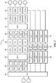
- FIG. 3 is a more detailed block diagram of a transmitter 21 constructed in accordance with principles of the present invention.
- the transmitter 21 includes a digital processing transmit section 31, a plurality of power amplifiers 32, an analog processing transmit section 33, and radio output ports 20.
- the digital processing transmit section 31 includes a digital matrix 30, linearizers 48, direct up-converters 36, and digital to analog converters 50.
- the analog processing transmit section 33 includes couplers 38, an analog matrix 34 and couplers 40.
- the digital matrix 30 distributes a plurality of carrier signals to the plurality of power amplifier channels after adjusting a gain and phase of each carrier signal based on feedback signals from couplers 40 such that the outputs of the plurality of power amplifiers are channeled by the analog matrix 34 to a selected one or more radio output ports 20.
- the outputs of the combiners 52 are coupled to the couplers 38.
- a sample of the power from each combiner 52 is coupled to an RF multiplexer 54 and fed back to the linearizers 48 via an analog to digital converter 56 and a direct down converter 58.
- Most of the power from combiners 52 are coupled by couplers 38 to the analog matrix 34, which channels the amplified up-sampled adjusted carrier signals to a selected one or more radio output ports 20.
- Samples of the outputs of the analog matrix 34 are coupled by couplers 40 to the RF multiplexer 54 to the digital matrix 30.
- the portion of the outputs of the analog matrix coupled by the couplers 40 are used as feedback signals that control gain and phase adjustments of the carrier signals received by the digital matrix 30.
- the feedback circuit 17 includes the couplers 40, the RF multiplexer 54, the ADC 56 and the DDC 58.
- the remainder of the power from the analog matrix 34 is coupled by couplers 40 to the duplexers 42, which in turn, couple the power to the output ports 20.
- the output ports 20 are coupled to antennas (not shown) which are oriented to transmit to one or more geographical sectors serviced by the radio.
- a single RF multiplexer 54 may be provided for the feedback signals from the couplers 38 and the couplers 40.
- one multiplexer is provided for the feedback from the couplers 38 and another multiplexer is provided for the feedback from the couplers 40.
- one embodiment is a radio for wireless communication that uses power pooling and direct up-conversion to reduce the number of radios required support all potential frequencies and modulation arrangements within a market space.
- the radio includes one or more radio output ports 20 fed by a plurality of power amplifiers 32.
- the radio includes a digital processing transmit section 31 and an analog processing transmit section 33.
- the digital processing transmit section 31 includes a digital matrix 30 that distributes a plurality of carrier signals to the plurality of power amplifiers 32.
- the digital matrix 30 adjusts a gain and phase of each carrier signal based on first feedback signals such that the outputs of the plurality of power amplifiers 32 are channeled to a selected one or more radio output ports 20.
- the digital processing section 31 also includes a plurality of direct up-converters 36 that are each in communication directly or indirectly with a corresponding one of the plurality of power amplifiers 32. Each direct up-converter up-samples the gain and phase adjusted carrier signals from the digital matrix 30.
- the plurality of power amplifiers 32 amplify the up-sampled adjusted carrier signals.
- the analog processing transmit section 33 includes an analog matrix 34, such as an analog Butler matrix, which channels the amplified up-sampled adjusted carrier signals to the selected one or more radio output ports 20.
- a plurality of couplers 40 couple first feedback signals from the analog matrix 34 to the digital matrix 30 to enable the digital matrix to adjust the gain and phase of each carrier signals, such that the outputs of the plurality of power amplifiers 32 are channeled to the selected one or more radio output ports 20.
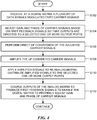
- a plurality of data signals modulated onto carrier signals are received at a digital matrix (step S102). Within the digital matrix, the gain and phase of each carrier signal is adjusted based on feedback signals so that the outputs of power amplifiers are directed to one or more radio output ports (step S104). Direct up-conversion of the adjusted carrier signals is performed (step S106). The up-converted carrier signals are amplified by a plurality of power amplifiers (step S108). The amplified signals are applied to an analog matrix which distributes the amplified signals to the selected one or more radio output ports (step S110). Outputs of the analog matrix are coupled as feedback signals to enable the digital matrix to adjust gain and phase of the carrier signals to cause distribution of the amplified signals to the selected one or more radio output ports (step S112).
- the gain and phase adjusted carrier signals are up-converted by a direct up-conversion module.
- the up-converted adjusted carrier signals are amplified in power amplifiers.
- the amplified up-converted adjusted carrier signals are applied to an analog matrix, which channels the signals to the selected one or more radio output ports. Outputs of the analog matrix are also used to provide feedback signals at the digital matrix to enable the digital matrix to adjust the phase and gain of the carrier signals as needed to cause the signals to be channeled to the selected one or more radio output ports.
- the present invention can be realized in hardware, or a combination of hardware and software. Any kind of computing system, or other apparatus adapted for carrying out the methods described herein, is suited to perform the functions described herein.
- a typical combination of hardware and software could be a specialized computer system, e.g., a router, having one or more processing elements and a computer program stored on a storage medium that, when loaded and executed, controls the computer system such that it carries out the methods described herein.
- the present invention can also be embedded in a computer program product, which comprises all the features enabling the implementation of the methods described herein, and which, when loaded in a computing system is able to carry out these methods.
- Storage medium refers to any volatile or nonvolatile storage device.
Description
- The present invention relates to wireless communications, and in particular to a long term evolution (LTE) radio system and method.
- Cellular radio base stations in wireless communication networks are characterized by having more than 100 product properties. As many as 20 of these properties define the radio portion of these base stations. These product properties drive different radio variants, some of which can be addressed by designing the radio to comply with multiple standards and or making the radio programmable. Making the radios programmable or to comply with multiple standards vastly decreases the number of radio variants needed for a base station.
- However, several irreducible factors limit the reduction in the number of radio variants needed. These include a number of transmit and receive antennas per sector, which can typically be 1, 2, 4 or 8 transmit antennas, and as many receive antennas. Another factor, is the required transmit power, which, for a base station covering a wide area could be 60 watts to 100 watts or greater. For a medium range base station the required power may be on the order of 6 watts, and for a local area base station may be less than 250 milli-watts. Yet another factor that affects the number of required radio variants is the set of bands of the evolved universal terrestrial radio access (EUTRA) network standard. Also, another factor is whether the radio is used indoors or outdoors. In consideration of these factors, there are about 960 radios needed to cover the complete market space.
- With about 960 radios required to cover the complete market space, manufacturers and cellular radio operators are faced with a daunting problem. The manufacturer has the problem of efficiently manufacturing a large number of radio variants and the operator has a problem of radio variant inventory, maintenance and handling. One way to reduce the number of radios required to cover the market space is by increasing the instantaneous bandwidth of each radio to reduce the number of radios needed to cover the EUTRA bands. For example, an instantaneous bandwidth of 400 Mega Hertz (MHz) enables an operator to span all EUTRA bands with only 4 radios. In this case the total number of radios required to span the market space is about 380, still a very large number.
- Therefore, there is a need for a radio system architecture that reduces a number of radios required to span the market space in a wireless communication system.
- Document
EP 2 178 204 A1 may be construed to disclose a radio transmission system comprising a plurality of power amplifiers (PAs); a plurality of Volterra Engine (VE) linearizers corresponding to the PAs; a plurality of feedback loops corresponding to the PAs; at least one digital hybrid matrix (DHM) coupled to the VE linearizers; and an analog hybrid matrix (AHM) coupled to the PAs, wherein the feedback loops are connected to the AHM and the VE linearizers but not to the PAs to reduce the number of feedback loops. Also included is a radio system comprising a plurality of PAs; a Volterra DHM (VDHM) coupled to the PAs; a plurality of feedback loops corresponding to the PAs; and an AHM coupled to the PAs, wherein the feedback loops are connected to the AHM but not to the PAs to reduce the number of feedback loops. - Document
US 2004/014500 A1 may be construed to disclose a power pooling apparatus that uniformly distributes sector loads in a mobile communication system. The power pooling apparatus comprises a distributor for distributing signals output from a signal generator according to respective sectors; a radio signal processor for performing signal processing to provide an output of the distributor to an antenna; and an adaptive signal processor for determining a characteristic matrix of the distributor by using an output in a predetermined position on a signal processing path of the radio signal processor, and providing the characteristic matrix of the distributor to the distributor - Document
WO 2007/134615 A1 may be construed to disclose a device for a wireless telecommunications system, comprising a first plurality of power amplifiers, each with an input and an output port. The device also comprises means for distributing a second plurality of input signals over the input ports of the first plurality of power amplifiers, and means for recreating a power amplified replica of said second plurality of input signals at the output ports of said first plurality of power amplifiers. The device is fed with the second plurality of input signals with a phase and amplitude distribution between the input signals, and comprises tapering means arranged to alter the phase and/or amplitude distribution of the input signals before being input to the distribution means, as well as means for reverse tapering at the output of the device. - According to the invention, there are provided an apparatus, a method and a computer-readable medium according to the independent claims. Developments are set forth in the dependent claims.
- There may be provided a method and system for an improved radio architecture in an LTE wireless communication system. There may be a radio for wireless communication that uses power pooling and direct up-conversion to reduce a number of radios required to span a market space. The radio may include radio output ports driven by a plurality of power amplifiers. The radio may include power pooling circuitry. The power pooling circuitry may adjust gains and phases of a plurality of carrier signals based on first feedback signals, and selectively direct output signals from the power amplifiers to a selected one or more radio outputs. The first feedback signals may be based on the selectively directed output signals. A plurality of direct up-converters may be each in communication directly or indirectly with a corresponding one of the plurality of power amplifiers. Each direct up-converter may up-sample the gain and phase adjusted carrier signals. The plurality of power amplifiers may amplify the up-sampled adjusted carrier signals and output the amplified the adjusted up-sampled carrier signals for transmission using the selected at least one radio output port.
- There may be a method of processing multiple signals in a transmitter of a wireless communication base station, where the transmitter has a plurality of power amplifiers and a plurality of radio output ports. The method may include receiving at a digital matrix a plurality of data-bearing carrier signals. The gain and phase of the carrier signals may be adjusted in the digital matrix based on first feedback signals such that the outputs of the power amplifiers are channeled to a selected one or more of the plurality of radio output ports. The gain and phase adjusted carrier signals may be up-converted by a direct up-conversion module. The up-converted adjusted carrier signals may be amplified in power amplifiers. The amplified up-converted adjusted carrier signals may be applied to an analog matrix which channels the signals to the selected one or more radio output ports. Outputs of the analog matrix may also be used to provide feedback signals at the digital matrix to enable the digital matrix to adjust the phase and gain of the carrier signals as needed to cause the signals to be channeled to the selected one or more radio output ports.
- There may be a radio in a wireless communication system. The radio may include a plurality of radio output ports, a transmitter, a plurality of antennas and a receiver. The transmitter may include a digital matrix to adjust the gain and phase of data-bearing carrier signals to be transmitted by the radio. The adjustments to the gain and phase of the carrier signals may be based on feedback signals such that the data-bearing carrier signals are channeled to a selected at least one radio output port. The transmitter may also include a plurality of direct up-converters that receive and up-convert the adjusted carrier signals. The transmitter may also include a plurality of power amplifiers that amplify the adjusted up-converted carrier signal. An analog matrix may distribute the amplified signals to the selected one or more radio output ports. A plurality of couplers in the transmitter couple may feedback signals from the analog matrix to the digital matrix. The receiver may receive signals from the antennas during reception and may, optionally, perform direct down-conversion of the received signals.
- A more complete understanding of the present invention, and the attendant advantages and features thereof, will be more readily understood by reference to the following detailed description when considered in conjunction with the accompanying drawings wherein:
-
FIG. 1 is a diagram of a wireless communication system constructed in accordance with principles of the present invention; -
FIG. 2 is a block diagram of a wireless transceiver constructed in accordance with principles of the present invention; -
FIG. 3 is a more detailed block diagram of a transmitter constructed in accordance with principles of the present invention; and -
FIG. 4 is a flow chart of an exemplary method of processing signals in a transmitter constructed according to principles of the present invention - Before describing in detail exemplary embodiments that are in accordance with the present invention, it is noted that the embodiments reside primarily in combinations of apparatus components and processing steps related to implementing a system and method for providing an efficient architecture for a long term evolution (LTE) radio. Accordingly, the system and method components have been represented where appropriate by conventional symbols in the drawings, showing only those specific details that are pertinent to understanding the embodiments of the present invention so as not to obscure the disclosure with details that will be readily apparent to those of ordinary skill in the art having the benefit of the description herein.
- As used herein, relational terms, such as "first" and "second," "top" and "bottom," and the like, may be used solely to distinguish one entity or element from another entity or element without necessarily requiring or implying any physical or logical relationship or order between such entities or elements.
- Referring now to the drawing figures, in which like reference designators denote like elements, there is shown in
FIG. 1 a diagram of a wireless communication system constructed in accordance with principles of the present invention and denoted generally as "10." Thewireless communication system 10 includes abase station 12 having aradio 14 that employspower pooling circuitry 16,feedback circuit 17, and direct upconverters 18 in the transmitter, as explained below. In some embodiments, theradio 14 may also employ direct down conversion in the receiver. - Power pooling is an arrangement by which the power available from a set of power amplifiers having low power can be controlled to coherently add at one or more output ports. The power per port is 1/N where N is the number of output ports to be used. Thus, for example, by pooling the outputs of four 25 watt (W) power amplifiers, one may deliver 100W at one port, 50W at two ports, 33W at three ports and 25W at four ports are all available from one single
radio hardware unit 14. Power pooling alone results in a reduction of a number of required radios to about 240. Power pooling 16 receives a feedback signal viafeedback circuit 17 based on the outputs of an analog matrix, as is described below. The feedback signal fromfeedback circuit 17 is used to determine gain and phase adjustments applied to carrier signals to enable the power to be directed to desired ports. - Direct up-conversion is a technology that enables the EUTRA bands to be covered by as few as 3 or 4 radios. Direct up-conversion involves up-sampling a signal by a factor of N to create an image spectrum at a transmit frequency which is selected by a filter. Direct down-conversion involves filtering and down sampling by a factor of N. Direct up/down sampling technology reduces the number of radio variants by a factor of 10/4, i.e., from about 960 to about 380. In some embodiments, the direct up-conversion and direct down conversion are programmable.
- Combining power pooling and direct up and down-conversion achieves a reduction in a number of required radios to span the market space by a factor of 10, resulting in the number of required radios being reduced to approximately 96.
- The
base station 12 includesoutput ports output ports 20. Note that theoutput ports 20 are shown separately from theradio 14 for convenience and ease of explanation, but that the output ports may be considered part of theradio 14. Thebase station 12 is in wireless communication with a plurality ofmobile subscriber units less output ports 20 and more or less mobile units 22 may be included in a wireless communication device than are shown inFIG. 1 . Also, a base station will typically include a plurality of radios, even though only one radio is shown inFIG. 1 . - An exemplary wireless transceiver (radio) 14 constructed in accordance with principles of the present invention is described with reference to
FIG. 2 . Data is received at the radio from a data source at adistribution network device 24, and data is transmitted from the radio to a location external to the radio via thedistribution network device 24. Thedistribution network device 24 provides an interface from the radio to the radio controlling equipment. More particularly, thedistribution network device 24 distributes multiple single channel samples to the digital transmitprocessors 26 and from thedigital receivers 28. -
FIG. 2 also shows a plurality of digital transmitprocessors 26 for processing each of a plurality of channels. Each digital transmitprocessor 26 performs baseband processing of the single carriers including, automatic level control (ALC), filtering (pulse shaping) equalization, gain/phase shifting and power measurements. A digital transmitprocessor 26 changes the sample rate of a single carrier signal to a rate that allows frequency shifting and summation into a multi-carrier signal. More particularly, the digital transmitprocessor 26 shifts the single carrier in preparation of summation into a multi-carrier signal. The digital transmitprocessor 26 adds the input up-sampled frequency-shifted carriers to create one multi-carrier signal per path. Power control can also be performed by the digital transmitprocessor 26. -
FIG. 2 also shows a digital Butler matrix (DBM) 30 that distributes the multi-carrier signals from the digital transmitprocessors 26 to the power amplifier chains with appropriate phase and gain adjustments so that the outputs of a plurality ofpower amplifiers 32 are channeled to a selected one or moreradio output ports 20. The phase and gain adjustments are based on feedback signals from an analog Butler matrix (ABM) 34. For example, the phase and gain adjustments may be adjusted to cause constructive interference at oneoutput port 20 and to cause destructive interference at anotheroutput port 20. Note that thematrix 30 is shown as a digital Butler matrix, but other matrix architectures may be employed. - The outputs of the
DBM 30 are fed to a direct up-converter (DUC) 36. The direct up-converter 36 processes the signals from the outputs of theDBM 30 to drive a digital analog converter (not shown inFIG. 2 ) to provide a desired radio frequency (RF) analog signal. Direct up-conversion is implemented by up-sampling by a factor of N and filtering about a carrier frequency of the desired RF signal. Linearizers (not shown inFIG. 2 ) receive feedback signals from thepower amplifiers 32 to linearize the outputs of thepower amplifiers 32. - The
power amplifiers 32 provide power amplification. The total power available to theoutput ports 20 is the total power of allavailable power amplifiers 32. For example, if each power amplifier is capable of providing 25W of output power, a total of 100W is available for distribution to one or more of theoutput ports 20. - A coupler/
circulator 38 for each power amplifier chain has a first output and a second output. The first output couples a sample of the output powers of eachpower amplifier 32 to provide feedback for power amplifier linearization. The second output of eachcoupler 38 couples the output of each power amplifier to an analog Butler matrix (ABM) 34. - The
ABM 34 combines the RF signals from thecouplers 38 and distributes these signals to a particular set of output ports. Note that although an analog Butler matrix is shown inFIG. 2 , other matrix architectures may be employed. The output ports to which the RF signals are distributed are selected based on the phase and gain adjustments of theDBM 30. A portion of the outputs of theABM 34 are coupled by thecouplers 40 back to theDBM 30 to provide feedback to determine in theDBM 30 the gain and phase adjustments necessary to channel the output power into the desiredports 20. The desired ports may be selected based on a desired output power for each port. -
Duplexers 42 couple the power fromcouplers 40 to theoutput ports 20 during transmission, and couple the power received from theoutput ports 20 to theanalog receivers 44 during reception. Theanalog receivers 44 amplify and demodulate received signals and couple the amplified and demodulated signals to the analog todigital converters 46. The analog todigital converters 46 convert the amplified, demodulated analog signals to digital signals. - The digital signals are coupled to the
digital receivers 28. Thedigital receivers 28 receive the multi-carrier digital signals and frequency-shift them to baseband. Thedigital receivers 28 perform filtering, equalization, gain and phase shifting, and power control functions. Note that in some embodiments, thereceiver components -
FIG. 3 is a more detailed block diagram of atransmitter 21 constructed in accordance with principles of the present invention. Thetransmitter 21 includes a digital processing transmitsection 31, a plurality ofpower amplifiers 32, an analog processing transmitsection 33, andradio output ports 20. The digital processing transmitsection 31 includes adigital matrix 30,linearizers 48, direct up-converters 36, and digital toanalog converters 50. The analog processing transmitsection 33 includescouplers 38, ananalog matrix 34 andcouplers 40. - The
digital matrix 30 distributes a plurality of carrier signals to the plurality of power amplifier channels after adjusting a gain and phase of each carrier signal based on feedback signals fromcouplers 40 such that the outputs of the plurality of power amplifiers are channeled by theanalog matrix 34 to a selected one or moreradio output ports 20. - The
linearizers 48 pre-amplify the gain/phase adjusted carrier signals to compensate for non-linearity of the power amplifiers based on feedback signals from thecouplers 38. The feedback signals from thecouplers 38 are samples of the signal from thepower amplifiers 32.
The direct up-converters 36 up-convert the carrier signals by over-sampling the carrier signals and filtering the over-sampled carrier signals about a desired carrier frequency. The digital toanalog converters 50 convert the digital carriers to analog RF signals. Thedigital analog converters 50 may operate at a sample rate that is based on a highest frequency of a carrier signal. The digital toanalog converters 50 may thus have fixed sample rates selected to up-convert the adjusted carrier signals to a plurality of separate frequency bands. The analog RF signals are fed to thepower amplifiers 32 which amplify the RF signals before they are combined by thecombiners 52. - In the configuration of
FIG. 3 there are two power amplifier chains per channel. For example the power amplifiers may be Doherty amplifiers, having one amplifier for amplifying peak power signals and having another amplifier for amplifying signals at less than peak power. In some embodiments, only a single power amplifier chain is provided for each channel. - The outputs of the
combiners 52 are coupled to thecouplers 38. A sample of the power from eachcombiner 52 is coupled to anRF multiplexer 54 and fed back to thelinearizers 48 via an analog todigital converter 56 and adirect down converter 58. Most of the power fromcombiners 52 are coupled bycouplers 38 to theanalog matrix 34, which channels the amplified up-sampled adjusted carrier signals to a selected one or moreradio output ports 20. - Samples of the outputs of the
analog matrix 34 are coupled bycouplers 40 to theRF multiplexer 54 to thedigital matrix 30. The portion of the outputs of the analog matrix coupled by thecouplers 40 are used as feedback signals that control gain and phase adjustments of the carrier signals received by thedigital matrix 30. Thefeedback circuit 17 includes thecouplers 40, theRF multiplexer 54, theADC 56 and theDDC 58. The remainder of the power from theanalog matrix 34 is coupled bycouplers 40 to theduplexers 42, which in turn, couple the power to theoutput ports 20. Theoutput ports 20 are coupled to antennas (not shown) which are oriented to transmit to one or more geographical sectors serviced by the radio. - Note that in one embodiment, a
single RF multiplexer 54 may be provided for the feedback signals from thecouplers 38 and thecouplers 40. In alternative embodiments, one multiplexer is provided for the feedback from thecouplers 38 and another multiplexer is provided for the feedback from thecouplers 40. - Thus, one embodiment is a radio for wireless communication that uses power pooling and direct up-conversion to reduce the number of radios required support all potential frequencies and modulation arrangements within a market space. The radio includes one or more
radio output ports 20 fed by a plurality ofpower amplifiers 32. The radio includes a digital processing transmitsection 31 and an analog processing transmitsection 33. - The digital processing transmit
section 31 includes adigital matrix 30 that distributes a plurality of carrier signals to the plurality ofpower amplifiers 32. Thedigital matrix 30 adjusts a gain and phase of each carrier signal based on first feedback signals such that the outputs of the plurality ofpower amplifiers 32 are channeled to a selected one or moreradio output ports 20. Thedigital processing section 31 also includes a plurality of direct up-converters 36 that are each in communication directly or indirectly with a corresponding one of the plurality ofpower amplifiers 32. Each direct up-converter up-samples the gain and phase adjusted carrier signals from thedigital matrix 30. The plurality ofpower amplifiers 32 amplify the up-sampled adjusted carrier signals. - The analog processing transmit
section 33 includes ananalog matrix 34, such as an analog Butler matrix, which channels the amplified up-sampled adjusted carrier signals to the selected one or moreradio output ports 20. A plurality ofcouplers 40 couple first feedback signals from theanalog matrix 34 to thedigital matrix 30 to enable the digital matrix to adjust the gain and phase of each carrier signals, such that the outputs of the plurality ofpower amplifiers 32 are channeled to the selected one or moreradio output ports 20. - An exemplary method of processing signals in a transmitter is described with reference to
FIG. 4 . A plurality of data signals modulated onto carrier signals are received at a digital matrix (step S102). Within the digital matrix, the gain and phase of each carrier signal is adjusted based on feedback signals so that the outputs of power amplifiers are directed to one or more radio output ports (step S104). Direct up-conversion of the adjusted carrier signals is performed (step S106). The up-converted carrier signals are amplified by a plurality of power amplifiers (step S108). The amplified signals are applied to an analog matrix which distributes the amplified signals to the selected one or more radio output ports (step S110). Outputs of the analog matrix are coupled as feedback signals to enable the digital matrix to adjust gain and phase of the carrier signals to cause distribution of the amplified signals to the selected one or more radio output ports (step S112). - Thus, one embodiment is a method of processing multiple signals in a transmitter of a wireless communication base station, where the transmitter has a plurality of power amplifiers and a plurality of radio output ports. The method includes receiving at a digital matrix a plurality of data-bearing carrier signals. The gain and phase of the carrier signals are adjusted in the digital matrix based on first feedback signals such that the outputs of the power amplifiers are channeled to a selected one or more of the plurality of radio output ports.
- The gain and phase adjusted carrier signals are up-converted by a direct up-conversion module. The up-converted adjusted carrier signals are amplified in power amplifiers. The amplified up-converted adjusted carrier signals are applied to an analog matrix, which channels the signals to the selected one or more radio output ports. Outputs of the analog matrix are also used to provide feedback signals at the digital matrix to enable the digital matrix to adjust the phase and gain of the carrier signals as needed to cause the signals to be channeled to the selected one or more radio output ports.
- The present invention can be realized in hardware, or a combination of hardware and software. Any kind of computing system, or other apparatus adapted for carrying out the methods described herein, is suited to perform the functions described herein. A typical combination of hardware and software could be a specialized computer system, e.g., a router, having one or more processing elements and a computer program stored on a storage medium that, when loaded and executed, controls the computer system such that it carries out the methods described herein. The present invention can also be embedded in a computer program product, which comprises all the features enabling the implementation of the methods described herein, and which, when loaded in a computing system is able to carry out these methods. Storage medium refers to any volatile or nonvolatile storage device.
- Computer program or application in the present context means any expression, in any language, code or notation, of a set of instructions intended to cause a system having an information processing capability to perform a particular function either directly or after either or both of the following a) conversion to another language, code or notation; b) reproduction in a different material form.
- In addition, unless mention was made above to the contrary, it should be noted that all of the accompanying drawings are not to scale. It will be appreciated by persons skilled in the art that the present invention is not limited to what has been particularly shown and described herein above. In addition, unless mention was made above to the contrary, it should be noted that all of the accompanying drawings are not to scale. A variety of modifications and variations are possible in light of the above teachings without departing from the scope of the invention, which is limited only by the following claims.
Claims (16)
- A radio (14) for wireless communication, the radio comprising:a plurality of radio output ports (20);a plurality of power amplifiers (32);power pooling circuitry, the power pooling circuitry being configured to:- adjust gains and phases of a plurality of carrier signals based on first feedback signals; and- selectively direct output signals from the power amplifiers (32) to N selected radio output ports, so that 1/N of a total output of all the power amplifiers (32) is allocated to each of the N selected radio output ports (20), N being less than a total number of the plurality of radio output ports (20), the first feedback signals being based on the selectively directed output signals;a plurality of direct up-converters (36), each of the plurality of direct up-converters being configured to communicate with a corresponding power amplifier (32), each of the plurality of direct up-converters being configured to process the adjusted carrier signals, the processing including up-sampling the adjusted carrier signals; andthe plurality of power amplifiers (32) being configured to:- amplify the adjusted up-sampled carrier signals and- output the amplified adjusted up-sampled carrier signals for transmission using the selected at least one radio output port (20).
- The radio of Claim 1, wherein:
the power pooling circuitry comprises:a digital matrix (30), the digital matrix being configured to:- distribute the plurality of carrier signals to the plurality of power amplifiers (32) via the direct up-converters (36), and- adjust a gain and phase of each carrier signal based on the first feedback signals such that outputs of the plurality of power amplifiers are channeled to the N selected radio output ports; and/orwherein the power pooling circuitry comprises:
an analog matrix (34), the analog matrix having a plurality of inputs configured to receive the amplified up-sampled adjusted carrier signals from a corresponding power amplifier (32) and having a plurality of outputs configured to channel the amplified up-sampled adjusted carrier signals to the N selected radio output ports (20). - The radio of Claim 1, further comprising first couplers (34) configured to couple the first feedback signals from the selectively directed output signals to the power pooling circuitry.
- The radio of Claim 3, further comprising an RF multiplexer (54), the RF multiplexer being configured to multiplex the first feedback signals from the plurality of first couplers (38).
- The radio of Claim 1, wherein the power pooling circuitry comprises a plurality of linearity devices (48), each linearity device:electrically coupled to at least one direct up-converter (36); andconfigured to provide linearity correction to a power amplifier (32) corresponding to the direct up-converter (36).
- The radio of Claim 5,wherein each of the plurality of power amplifiers (32) has a power amplifier output and the linearity devices (48) are configured to receive second feedback signals from a corresponding power amplifier output; and optionally,further comprising a plurality of second couplers (40), the plurality of second couplers coupled to the power amplifiers and configured to provide the second feedback signals; and optionally,wherein the radio is configured to convert the multiplexed first feedback signals to digital signals (56) before coupling the first feedback signals to the power pooling circuitry.
- The radio of Claim 1,further comprising a plurality of digital-to-analog converters, DACs, (50), each DAC coupled to a corresponding power amplifier (32), the plurality of DACs (50) being configured to operate at a sample rate that is based on a highest frequency of a carrier signal; orwherein the radio is configured to select the N selected radio output ports based on a desired power per radio output port (20).
- The radio of Claim 1, further comprising a plurality of antennas, each antenna coupled to a corresponding radio output port (20).
- The radio of Claim 8, wherein each antenna is directed to a different geographical sector serviced by the radio (21).
- The radio of claim 1, all features of claim 2, claim 3 and claim 8 for use in a wireless communication system, the radio comprising:a transmitter, the transmitter including:- the digital matrix (30);- the plurality of direct up-converters (36);- the plurality of power amplifiers (32);- the analog matrix (34);- the plurality of couplers (40); and- the plurality of antennas, each antenna coupled to a radio output port (20); anda receiver (44, 46, 28), the receiver receiving signals from the antennas during reception.
- The radio of Claim 10, wherein:the receiver (44, 46, 28) comprises a direct down-conversion unit, the direct down-conversion unit being configured to down-convert the received signals via direct sampling of the received signals; orthe direct up-converters (36) include digital to analog converters having fixed sample rates selected to up-convert the adjusted carrier signals to a plurality of separate frequency bands.
- The radio of Claim 10, wherein a selected one of the output ports (20) receives power from a plurality of the power amplifiers (32).
- The radio of Claim 12, wherein the power from the plurality of power amplifiers (32) is combined by the analog matrix (34).
- The radio of claim 1, wherein the power pooling circuitry is further configured to adjust gains and phases of a plurality of carrier signals based on first feedback signals such that outputs of the plurality of power amplifiers add coherently only at the N selected ones of the plurality of radio output ports and destructively interfere at remaining radio output ports.
- A method for processing multiple signals in a transmitter of a wireless communication base station, the transmitter having a plurality of power amplifiers (32) and a plurality of radio output ports (20), the method comprising:receiving (S102), at a digital matrix (30), a plurality of data-bearing carrier signals;selecting N radio output ports, N being less than a total number of the plurality of radio output ports (20);adjusting (S104) gain and phase of the carrier signals in the digital matrix (30) and distributing the adjusted carrier signals to the plurality of power amplifiers (32), the adjusting based on first feedback signals such that outputs of the power amplifiers are channeled to the N selected radio output ports (20), so that 1/N of a total output power of all the power amplifiers (32) is allocated to each of the N selected radio output ports (20);performing (S106) direct up-conversion of the adjusted carrier signals;amplifying (S108) the up-converted adjusted carrier signals in the power amplifiers (32);applying (S110) the amplified up-converted adjusted carrier signals to an analog matrix (34), the analog matrix channeling the applied signals to the selected at least one radio output port (20); andcoupling (S112) outputs of the analog matrix (34) to produce the first feedback signals at the digital matrix (30) to enable the digital matrix to adjust the phase and gain of the carrier signals.
- Computer readable storage medium storing a program that, when loaded and executed, controls a computer system to perform all steps of the method of claim 15.
Applications Claiming Priority (2)
| Application Number | Priority Date | Filing Date | Title |
|---|---|---|---|
| US13/194,508 US8750210B2 (en) | 2011-07-29 | 2011-07-29 | Wireless long term evolution radio architecture system and method |
| PCT/IB2012/052925 WO2013017965A1 (en) | 2011-07-29 | 2012-06-08 | Wireless long term evolution radio architecture system and method |
Publications (2)
| Publication Number | Publication Date |
|---|---|
| EP2737631A1 EP2737631A1 (en) | 2014-06-04 |
| EP2737631B1 true EP2737631B1 (en) | 2019-03-06 |
Family
ID=46514715
Family Applications (1)
| Application Number | Title | Priority Date | Filing Date |
|---|---|---|---|
| EP12735630.1A Active EP2737631B1 (en) | 2011-07-29 | 2012-06-08 | Wireless long term evolution radio architecture system and method |
Country Status (4)
| Country | Link |
|---|---|
| US (1) | US8750210B2 (en) |
| EP (1) | EP2737631B1 (en) |
| MX (1) | MX2014001120A (en) |
| WO (1) | WO2013017965A1 (en) |
Families Citing this family (5)
| Publication number | Priority date | Publication date | Assignee | Title |
|---|---|---|---|---|
| US8750174B2 (en) * | 2012-03-30 | 2014-06-10 | Broadcom Corporation | Dual carrier separation |
| US9197327B2 (en) * | 2012-09-04 | 2015-11-24 | Cisco Technology, Inc. | Optical communication transmitter system |
| WO2015168696A1 (en) * | 2014-05-02 | 2015-11-05 | Parkervision, Inc. | Antenna array for communication system |
| KR20180037556A (en) | 2016-10-04 | 2018-04-12 | 삼성전자주식회사 | Wireless communication apparatus and controling method therefor |
| US11039850B2 (en) | 2018-02-28 | 2021-06-22 | Gi Supply | Endoscopic tool with suction for facilitating injection of a fluid into a submucosal layer of tissue |
Family Cites Families (17)
| Publication number | Priority date | Publication date | Assignee | Title |
|---|---|---|---|---|
| US5574967A (en) * | 1994-01-11 | 1996-11-12 | Ericsson Ge Mobile Communications, Inc. | Waste energy control and management in power amplifiers |
| US5955920A (en) * | 1997-07-29 | 1999-09-21 | Metawave Communications Corporation | Signal feed matrix LPA reduction system and method |
| US6006111A (en) * | 1997-10-08 | 1999-12-21 | Nortel Networks Corporation | Self-balancing matrix amplifier |
| US5966048A (en) * | 1997-11-25 | 1999-10-12 | Hughes Electronics Corporation | Low IMD amplification method and apparatus |
| US6381212B1 (en) * | 1998-06-17 | 2002-04-30 | Radio Frequency Systems, Inc. | Power sharing amplifier system for amplifying multiple input signals with shared power amplifiers |
| US6243038B1 (en) * | 1998-12-17 | 2001-06-05 | Metawave Communications Corporation | System and method providing amplification of narrow band signals with multi-channel amplifiers |
| KR100703337B1 (en) | 2002-07-13 | 2007-04-03 | 삼성전자주식회사 | Adaptive power pooling method and apparatus in a mobile communication system |
| US7206355B2 (en) | 2002-12-02 | 2007-04-17 | Nortel Networks Limited | Digitally convertible radio |
| US7248656B2 (en) | 2002-12-02 | 2007-07-24 | Nortel Networks Limited | Digital convertible radio SNR optimization |
| AU2002360071A1 (en) * | 2002-12-20 | 2004-07-14 | Telefonaktiebolaget Lm Ericsson (Publ) | Peak power limitation in an amplifier pooling scenario |
| US7606322B2 (en) * | 2004-10-07 | 2009-10-20 | Microelectronics Technology Inc. | Digital pre-distortion technique using nonlinear filters |
| US7558541B2 (en) | 2004-12-01 | 2009-07-07 | The Boeing Company | Amplifier gain and phase stabilizer |
| ATE446596T1 (en) | 2006-05-19 | 2009-11-15 | Ericsson Telefon Ab L M | SHARED POWER AMPLIFIER DEVICE FOR USE IN A WIRELESS TELECOMMUNICATIONS SYSTEM |
| WO2008119164A1 (en) | 2007-03-30 | 2008-10-09 | Nortel Networks Limited | Amplifier pre-distortion systems and methods |
| US8213880B2 (en) | 2008-10-15 | 2012-07-03 | Rockstar Bidco, LP | Minimum feedback radio architecture with digitally configurable adaptive linearization |
| US8553807B2 (en) | 2008-10-20 | 2013-10-08 | Apple Inc. | Methods and systems for programmable digital up-conversion |
| US20120328050A1 (en) * | 2011-06-21 | 2012-12-27 | Telefonaktiebolaget L M Ericsson (Publ) | Centralized adaptor architecture for power amplifier linearizations in advanced wireless communication systems |
-
2011
- 2011-07-29 US US13/194,508 patent/US8750210B2/en active Active
-
2012
- 2012-06-08 WO PCT/IB2012/052925 patent/WO2013017965A1/en active Application Filing
- 2012-06-08 EP EP12735630.1A patent/EP2737631B1/en active Active
- 2012-06-08 MX MX2014001120A patent/MX2014001120A/en active IP Right Grant
Non-Patent Citations (1)
| Title |
|---|
| None * |
Also Published As
| Publication number | Publication date |
|---|---|
| US8750210B2 (en) | 2014-06-10 |
| US20130028178A1 (en) | 2013-01-31 |
| MX2014001120A (en) | 2014-02-27 |
| WO2013017965A1 (en) | 2013-02-07 |
| EP2737631A1 (en) | 2014-06-04 |
Similar Documents
| Publication | Publication Date | Title |
|---|---|---|
| CN102948081B (en) | There is remote radio frequency head unit and the method for wideband power amplifer | |
| US9923524B2 (en) | Digital pre-distortion for multi-antenna systems | |
| US9461590B2 (en) | Envelope tracking in connection with simultaneous transmission in one or more frequency bands | |
| US8665845B2 (en) | Communication system, network element and method for antenna array beam-forming | |
| US20180323813A1 (en) | High efficiency, remotely reconfigurable remote radio head unit system and method for wireless communications | |
| US9106453B2 (en) | Remote radio head unit system with wideband power amplifier and method | |
| CN102082752B (en) | Digital predistortion processing method and equipment | |
| US10623049B2 (en) | Digital predistortion processing method and apparatus | |
| US20070110177A1 (en) | RF power distribution in the frequency domain | |
| US8923370B2 (en) | Radio communication apparatus method | |
| US20140024325A1 (en) | Method and system for providing wireless base station radio with non-disruptive service power class switching | |
| KR20100042233A (en) | Minimum feedback radio architecture with digitally configurable adaptive linearization | |
| EP2737631B1 (en) | Wireless long term evolution radio architecture system and method | |
| KR20130103732A (en) | Apparatus and method for a multiband radio operating in a wireless network | |
| US20090233644A1 (en) | Multiple carrier radio systems and methods employing polar active antenna elements | |
| JP2000228646A (en) | Portable mobile terminal and transmitter | |
| JP2005348116A (en) | Radio communication device | |
| JP4624517B2 (en) | Base station with active antenna | |
| US10637525B2 (en) | Wireless device and wireless communication method | |
| EP1890386A1 (en) | Digital front-end for multi-standard transmitter and multi-standard base station | |
| CN106489277B (en) | A kind of method for handling carriers and device based on identical networking | |
| KR20050077855A (en) | A method of transmission power control of a power amplifier for a wireless telecommunication system | |
| KR20050034923A (en) | System for controlling linear power amplification |
Legal Events
| Date | Code | Title | Description |
|---|---|---|---|
| PUAI | Public reference made under article 153(3) epc to a published international application that has entered the european phase |
Free format text: ORIGINAL CODE: 0009012 |
|
| 17P | Request for examination filed |
Effective date: 20140123 |
|
| AK | Designated contracting states |
Kind code of ref document: A1 Designated state(s): AL AT BE BG CH CY CZ DE DK EE ES FI FR GB GR HR HU IE IS IT LI LT LU LV MC MK MT NL NO PL PT RO RS SE SI SK SM TR |
|
| DAX | Request for extension of the european patent (deleted) | ||
| GRAP | Despatch of communication of intention to grant a patent |
Free format text: ORIGINAL CODE: EPIDOSNIGR1 |
|
| STAA | Information on the status of an ep patent application or granted ep patent |
Free format text: STATUS: GRANT OF PATENT IS INTENDED |
|
| INTG | Intention to grant announced |
Effective date: 20181026 |
|
| GRAS | Grant fee paid |
Free format text: ORIGINAL CODE: EPIDOSNIGR3 |
|
| GRAA | (expected) grant |
Free format text: ORIGINAL CODE: 0009210 |
|
| STAA | Information on the status of an ep patent application or granted ep patent |
Free format text: STATUS: THE PATENT HAS BEEN GRANTED |
|
| AK | Designated contracting states |
Kind code of ref document: B1 Designated state(s): AL AT BE BG CH CY CZ DE DK EE ES FI FR GB GR HR HU IE IS IT LI LT LU LV MC MK MT NL NO PL PT RO RS SE SI SK SM TR |
|
| REG | Reference to a national code |
Ref country code: GB Ref legal event code: FG4D |
|
| REG | Reference to a national code |
Ref country code: CH Ref legal event code: EP Ref country code: AT Ref legal event code: REF Ref document number: 1105945 Country of ref document: AT Kind code of ref document: T Effective date: 20190315 |
|
| REG | Reference to a national code |
Ref country code: DE Ref legal event code: R096 Ref document number: 602012057443 Country of ref document: DE |
|
| REG | Reference to a national code |
Ref country code: IE Ref legal event code: FG4D |
|
| REG | Reference to a national code |
Ref country code: NL Ref legal event code: MP Effective date: 20190306 |
|
| REG | Reference to a national code |
Ref country code: LT Ref legal event code: MG4D |
|
| PG25 | Lapsed in a contracting state [announced via postgrant information from national office to epo] |
Ref country code: SE Free format text: LAPSE BECAUSE OF FAILURE TO SUBMIT A TRANSLATION OF THE DESCRIPTION OR TO PAY THE FEE WITHIN THE PRESCRIBED TIME-LIMIT Effective date: 20190306 Ref country code: FI Free format text: LAPSE BECAUSE OF FAILURE TO SUBMIT A TRANSLATION OF THE DESCRIPTION OR TO PAY THE FEE WITHIN THE PRESCRIBED TIME-LIMIT Effective date: 20190306 Ref country code: NO Free format text: LAPSE BECAUSE OF FAILURE TO SUBMIT A TRANSLATION OF THE DESCRIPTION OR TO PAY THE FEE WITHIN THE PRESCRIBED TIME-LIMIT Effective date: 20190606 Ref country code: LT Free format text: LAPSE BECAUSE OF FAILURE TO SUBMIT A TRANSLATION OF THE DESCRIPTION OR TO PAY THE FEE WITHIN THE PRESCRIBED TIME-LIMIT Effective date: 20190306 |
|
| PG25 | Lapsed in a contracting state [announced via postgrant information from national office to epo] |
Ref country code: BG Free format text: LAPSE BECAUSE OF FAILURE TO SUBMIT A TRANSLATION OF THE DESCRIPTION OR TO PAY THE FEE WITHIN THE PRESCRIBED TIME-LIMIT Effective date: 20190606 Ref country code: GR Free format text: LAPSE BECAUSE OF FAILURE TO SUBMIT A TRANSLATION OF THE DESCRIPTION OR TO PAY THE FEE WITHIN THE PRESCRIBED TIME-LIMIT Effective date: 20190607 Ref country code: HR Free format text: LAPSE BECAUSE OF FAILURE TO SUBMIT A TRANSLATION OF THE DESCRIPTION OR TO PAY THE FEE WITHIN THE PRESCRIBED TIME-LIMIT Effective date: 20190306 Ref country code: LV Free format text: LAPSE BECAUSE OF FAILURE TO SUBMIT A TRANSLATION OF THE DESCRIPTION OR TO PAY THE FEE WITHIN THE PRESCRIBED TIME-LIMIT Effective date: 20190306 Ref country code: NL Free format text: LAPSE BECAUSE OF FAILURE TO SUBMIT A TRANSLATION OF THE DESCRIPTION OR TO PAY THE FEE WITHIN THE PRESCRIBED TIME-LIMIT Effective date: 20190306 Ref country code: RS Free format text: LAPSE BECAUSE OF FAILURE TO SUBMIT A TRANSLATION OF THE DESCRIPTION OR TO PAY THE FEE WITHIN THE PRESCRIBED TIME-LIMIT Effective date: 20190306 |
|
| REG | Reference to a national code |
Ref country code: AT Ref legal event code: MK05 Ref document number: 1105945 Country of ref document: AT Kind code of ref document: T Effective date: 20190306 |
|
| PG25 | Lapsed in a contracting state [announced via postgrant information from national office to epo] |
Ref country code: IT Free format text: LAPSE BECAUSE OF FAILURE TO SUBMIT A TRANSLATION OF THE DESCRIPTION OR TO PAY THE FEE WITHIN THE PRESCRIBED TIME-LIMIT Effective date: 20190306 Ref country code: ES Free format text: LAPSE BECAUSE OF FAILURE TO SUBMIT A TRANSLATION OF THE DESCRIPTION OR TO PAY THE FEE WITHIN THE PRESCRIBED TIME-LIMIT Effective date: 20190306 Ref country code: RO Free format text: LAPSE BECAUSE OF FAILURE TO SUBMIT A TRANSLATION OF THE DESCRIPTION OR TO PAY THE FEE WITHIN THE PRESCRIBED TIME-LIMIT Effective date: 20190306 Ref country code: CZ Free format text: LAPSE BECAUSE OF FAILURE TO SUBMIT A TRANSLATION OF THE DESCRIPTION OR TO PAY THE FEE WITHIN THE PRESCRIBED TIME-LIMIT Effective date: 20190306 Ref country code: EE Free format text: LAPSE BECAUSE OF FAILURE TO SUBMIT A TRANSLATION OF THE DESCRIPTION OR TO PAY THE FEE WITHIN THE PRESCRIBED TIME-LIMIT Effective date: 20190306 Ref country code: AL Free format text: LAPSE BECAUSE OF FAILURE TO SUBMIT A TRANSLATION OF THE DESCRIPTION OR TO PAY THE FEE WITHIN THE PRESCRIBED TIME-LIMIT Effective date: 20190306 Ref country code: PT Free format text: LAPSE BECAUSE OF FAILURE TO SUBMIT A TRANSLATION OF THE DESCRIPTION OR TO PAY THE FEE WITHIN THE PRESCRIBED TIME-LIMIT Effective date: 20190706 Ref country code: SK Free format text: LAPSE BECAUSE OF FAILURE TO SUBMIT A TRANSLATION OF THE DESCRIPTION OR TO PAY THE FEE WITHIN THE PRESCRIBED TIME-LIMIT Effective date: 20190306 |
|
| PG25 | Lapsed in a contracting state [announced via postgrant information from national office to epo] |
Ref country code: PL Free format text: LAPSE BECAUSE OF FAILURE TO SUBMIT A TRANSLATION OF THE DESCRIPTION OR TO PAY THE FEE WITHIN THE PRESCRIBED TIME-LIMIT Effective date: 20190306 Ref country code: SM Free format text: LAPSE BECAUSE OF FAILURE TO SUBMIT A TRANSLATION OF THE DESCRIPTION OR TO PAY THE FEE WITHIN THE PRESCRIBED TIME-LIMIT Effective date: 20190306 |
|
| REG | Reference to a national code |
Ref country code: DE Ref legal event code: R097 Ref document number: 602012057443 Country of ref document: DE |
|
| PG25 | Lapsed in a contracting state [announced via postgrant information from national office to epo] |
Ref country code: AT Free format text: LAPSE BECAUSE OF FAILURE TO SUBMIT A TRANSLATION OF THE DESCRIPTION OR TO PAY THE FEE WITHIN THE PRESCRIBED TIME-LIMIT Effective date: 20190306 Ref country code: IS Free format text: LAPSE BECAUSE OF FAILURE TO SUBMIT A TRANSLATION OF THE DESCRIPTION OR TO PAY THE FEE WITHIN THE PRESCRIBED TIME-LIMIT Effective date: 20190706 |
|
| PLBE | No opposition filed within time limit |
Free format text: ORIGINAL CODE: 0009261 |
|
| STAA | Information on the status of an ep patent application or granted ep patent |
Free format text: STATUS: NO OPPOSITION FILED WITHIN TIME LIMIT |
|
| PG25 | Lapsed in a contracting state [announced via postgrant information from national office to epo] |
Ref country code: MC Free format text: LAPSE BECAUSE OF FAILURE TO SUBMIT A TRANSLATION OF THE DESCRIPTION OR TO PAY THE FEE WITHIN THE PRESCRIBED TIME-LIMIT Effective date: 20190306 Ref country code: DK Free format text: LAPSE BECAUSE OF FAILURE TO SUBMIT A TRANSLATION OF THE DESCRIPTION OR TO PAY THE FEE WITHIN THE PRESCRIBED TIME-LIMIT Effective date: 20190306 |
|
| REG | Reference to a national code |
Ref country code: CH Ref legal event code: PL |
|
| 26N | No opposition filed |
Effective date: 20191209 |
|
| PG25 | Lapsed in a contracting state [announced via postgrant information from national office to epo] |
Ref country code: SI Free format text: LAPSE BECAUSE OF FAILURE TO SUBMIT A TRANSLATION OF THE DESCRIPTION OR TO PAY THE FEE WITHIN THE PRESCRIBED TIME-LIMIT Effective date: 20190306 |
|
| REG | Reference to a national code |
Ref country code: BE Ref legal event code: MM Effective date: 20190630 |
|
| PG25 | Lapsed in a contracting state [announced via postgrant information from national office to epo] |
Ref country code: TR Free format text: LAPSE BECAUSE OF FAILURE TO SUBMIT A TRANSLATION OF THE DESCRIPTION OR TO PAY THE FEE WITHIN THE PRESCRIBED TIME-LIMIT Effective date: 20190306 |
|
| PG25 | Lapsed in a contracting state [announced via postgrant information from national office to epo] |
Ref country code: IE Free format text: LAPSE BECAUSE OF NON-PAYMENT OF DUE FEES Effective date: 20190608 |
|
| PG25 | Lapsed in a contracting state [announced via postgrant information from national office to epo] |
Ref country code: CH Free format text: LAPSE BECAUSE OF NON-PAYMENT OF DUE FEES Effective date: 20190630 Ref country code: LI Free format text: LAPSE BECAUSE OF NON-PAYMENT OF DUE FEES Effective date: 20190630 Ref country code: LU Free format text: LAPSE BECAUSE OF NON-PAYMENT OF DUE FEES Effective date: 20190608 Ref country code: BE Free format text: LAPSE BECAUSE OF NON-PAYMENT OF DUE FEES Effective date: 20190630 |
|
| PG25 | Lapsed in a contracting state [announced via postgrant information from national office to epo] |
Ref country code: CY Free format text: LAPSE BECAUSE OF FAILURE TO SUBMIT A TRANSLATION OF THE DESCRIPTION OR TO PAY THE FEE WITHIN THE PRESCRIBED TIME-LIMIT Effective date: 20190306 |
|
| PG25 | Lapsed in a contracting state [announced via postgrant information from national office to epo] |
Ref country code: HU Free format text: LAPSE BECAUSE OF FAILURE TO SUBMIT A TRANSLATION OF THE DESCRIPTION OR TO PAY THE FEE WITHIN THE PRESCRIBED TIME-LIMIT; INVALID AB INITIO Effective date: 20120608 Ref country code: MT Free format text: LAPSE BECAUSE OF FAILURE TO SUBMIT A TRANSLATION OF THE DESCRIPTION OR TO PAY THE FEE WITHIN THE PRESCRIBED TIME-LIMIT Effective date: 20190306 |
|
| PG25 | Lapsed in a contracting state [announced via postgrant information from national office to epo] |
Ref country code: MK Free format text: LAPSE BECAUSE OF FAILURE TO SUBMIT A TRANSLATION OF THE DESCRIPTION OR TO PAY THE FEE WITHIN THE PRESCRIBED TIME-LIMIT Effective date: 20190306 |
|
| PGFP | Annual fee paid to national office [announced via postgrant information from national office to epo] |
Ref country code: FR Payment date: 20220627 Year of fee payment: 11 |
|
| PGFP | Annual fee paid to national office [announced via postgrant information from national office to epo] |
Ref country code: DE Payment date: 20220629 Year of fee payment: 11 |
|
| PGFP | Annual fee paid to national office [announced via postgrant information from national office to epo] |
Ref country code: GB Payment date: 20230627 Year of fee payment: 12 |
|
| REG | Reference to a national code |
Ref country code: DE Ref legal event code: R119 Ref document number: 602012057443 Country of ref document: DE |