EP2737191B1 - Turbo-compressor train with rolling bearings and single lube pump - Google Patents
Turbo-compressor train with rolling bearings and single lube pump Download PDFInfo
- Publication number
- EP2737191B1 EP2737191B1 EP12740578.5A EP12740578A EP2737191B1 EP 2737191 B1 EP2737191 B1 EP 2737191B1 EP 12740578 A EP12740578 A EP 12740578A EP 2737191 B1 EP2737191 B1 EP 2737191B1
- Authority
- EP
- European Patent Office
- Prior art keywords
- compressor
- train
- shaft
- turbo
- lube pump
- Prior art date
- Legal status (The legal status is an assumption and is not a legal conclusion. Google has not performed a legal analysis and makes no representation as to the accuracy of the status listed.)
- Active
Links
Images






Classifications
-
- F—MECHANICAL ENGINEERING; LIGHTING; HEATING; WEAPONS; BLASTING
- F01—MACHINES OR ENGINES IN GENERAL; ENGINE PLANTS IN GENERAL; STEAM ENGINES
- F01D—NON-POSITIVE DISPLACEMENT MACHINES OR ENGINES, e.g. STEAM TURBINES
- F01D25/00—Component parts, details, or accessories, not provided for in, or of interest apart from, other groups
- F01D25/16—Arrangement of bearings; Supporting or mounting bearings in casings
-
- F—MECHANICAL ENGINEERING; LIGHTING; HEATING; WEAPONS; BLASTING
- F01—MACHINES OR ENGINES IN GENERAL; ENGINE PLANTS IN GENERAL; STEAM ENGINES
- F01D—NON-POSITIVE DISPLACEMENT MACHINES OR ENGINES, e.g. STEAM TURBINES
- F01D25/00—Component parts, details, or accessories, not provided for in, or of interest apart from, other groups
- F01D25/18—Lubricating arrangements
-
- F—MECHANICAL ENGINEERING; LIGHTING; HEATING; WEAPONS; BLASTING
- F02—COMBUSTION ENGINES; HOT-GAS OR COMBUSTION-PRODUCT ENGINE PLANTS
- F02C—GAS-TURBINE PLANTS; AIR INTAKES FOR JET-PROPULSION PLANTS; CONTROLLING FUEL SUPPLY IN AIR-BREATHING JET-PROPULSION PLANTS
- F02C6/00—Plural gas-turbine plants; Combinations of gas-turbine plants with other apparatus; Adaptations of gas-turbine plants for special use
- F02C6/04—Gas-turbine plants providing heated or pressurised working fluid for other apparatus, e.g. without mechanical power output
- F02C6/06—Gas-turbine plants providing heated or pressurised working fluid for other apparatus, e.g. without mechanical power output providing compressed gas
-
- F—MECHANICAL ENGINEERING; LIGHTING; HEATING; WEAPONS; BLASTING
- F02—COMBUSTION ENGINES; HOT-GAS OR COMBUSTION-PRODUCT ENGINE PLANTS
- F02C—GAS-TURBINE PLANTS; AIR INTAKES FOR JET-PROPULSION PLANTS; CONTROLLING FUEL SUPPLY IN AIR-BREATHING JET-PROPULSION PLANTS
- F02C7/00—Features, components parts, details or accessories, not provided for in, or of interest apart form groups F02C1/00 - F02C6/00; Air intakes for jet-propulsion plants
- F02C7/32—Arrangement, mounting, or driving, of auxiliaries
-
- F—MECHANICAL ENGINEERING; LIGHTING; HEATING; WEAPONS; BLASTING
- F02—COMBUSTION ENGINES; HOT-GAS OR COMBUSTION-PRODUCT ENGINE PLANTS
- F02C—GAS-TURBINE PLANTS; AIR INTAKES FOR JET-PROPULSION PLANTS; CONTROLLING FUEL SUPPLY IN AIR-BREATHING JET-PROPULSION PLANTS
- F02C7/00—Features, components parts, details or accessories, not provided for in, or of interest apart form groups F02C1/00 - F02C6/00; Air intakes for jet-propulsion plants
- F02C7/36—Power transmission arrangements between the different shafts of the gas turbine plant, or between the gas-turbine plant and the power user
-
- F—MECHANICAL ENGINEERING; LIGHTING; HEATING; WEAPONS; BLASTING
- F05—INDEXING SCHEMES RELATING TO ENGINES OR PUMPS IN VARIOUS SUBCLASSES OF CLASSES F01-F04
- F05D—INDEXING SCHEME FOR ASPECTS RELATING TO NON-POSITIVE-DISPLACEMENT MACHINES OR ENGINES, GAS-TURBINES OR JET-PROPULSION PLANTS
- F05D2260/00—Function
- F05D2260/40—Transmission of power
-
- Y—GENERAL TAGGING OF NEW TECHNOLOGICAL DEVELOPMENTS; GENERAL TAGGING OF CROSS-SECTIONAL TECHNOLOGIES SPANNING OVER SEVERAL SECTIONS OF THE IPC; TECHNICAL SUBJECTS COVERED BY FORMER USPC CROSS-REFERENCE ART COLLECTIONS [XRACs] AND DIGESTS
- Y02—TECHNOLOGIES OR APPLICATIONS FOR MITIGATION OR ADAPTATION AGAINST CLIMATE CHANGE
- Y02T—CLIMATE CHANGE MITIGATION TECHNOLOGIES RELATED TO TRANSPORTATION
- Y02T50/00—Aeronautics or air transport
- Y02T50/60—Efficient propulsion technologies, e.g. for aircraft
Definitions
- the present disclosure generally relates to mechanisms and techniques for providing an entire turbo-compressor train with a single lube pump and a single lubrication oil medium.
- EP 1 930 553 A2 discloses a gas turbine engine including a centrifugal compressor having a rotor and a thrust bearing disposed in connection with the rotor.
- US 4 834 622 A discloses a turbo-compressor train with a gas turbine engine, a load compressor, an accessory gearbox, a lube pump and ball bearings.
- DE 26 28 401 A1 discloses a gas turbine engine with an alternator using synthetic oil, ball bearings and a single oil pump.
- EP 1 683 943 A2 discloses a turbogenerator with a single oil pump for a gas turbine engine and a generator.
- US 2007/0060442 A1 discloses a turbo-compressor train with a gas turbine engine, a centrifugal compressor and an additional gearbox.
- Gas turbine engines are used in many sectors of the industry, from military to power generation. They are used mainly to produce electrical energy. However, some gas turbine engines are used to propel various vehicles, airplanes, ships, etc. In the oil and gas field, the gas turbine engines are used to drive compressors, pumps and/or generators. As shown in Figure 1 , a gas turbine engine 12 may be connected to a compressor or generator 14 and to an auxiliary equipment 16. A gear box 18 or other equipment may be provided between the gas turbine engine 12 and the compressor or generator 14. All these elements form a turbo-compressor train 10.
- the gas turbine engine 12 may include a compressor 20 that is configured to receive a gas (e.g., air) at an input 22 and to provide the gas compressed to a predetermined pressure at an outlet 24.
- the compressed gas is then input to a combustor 26 where it is mixed with a fuel provided from a line 28.
- the mixture of gas and fuel is ignited and the hot gases at high pressure are provided to an input 30 of an expander 32.
- the exhaust gases are then released at output 34 of the expander 32.
- the expansion of the hot gases through the expander 32 determines a rotation of a rotoric part (not shown) which is coupled, through the gear box 18 to a shaft of the compressor 14.
- the compressor 14 is driven by the expander 32.
- One or more of the components of the turbo-compressor train 10 involves heavy rotoric parts (e.g., shaft, impeller, etc.) that rotate at a high speed. In order to promote the rotational motion of these components and to minimize the friction, various bearing units are provided in the train. A few arrangements of conventional turbo-compressor trains are discussed next.
- Figures 2A-C show the train 10 of Figure 1 in which some elements have rolling bearings and the remaining elements have hydro-dynamic bearings. Those elements having the rolling bearings are identified with A and those having the hydro-dynamic bearings are identified with B. Further, it is noted that the rolling bearings need to use synthetic oil while the hydro-dynamic bearings need to use mineral oil. Thus, the arrangements shown in Figures 2A and 2B need two lube pumps, one for each type of bearings while the arrangement shown in Figure 2C uses one lube pump and the mineral oil. These arrangements have a higher weight and maintenance cost due to the dual lube pump, they have a large footprint and require higher plant complexity. A disadvantage of the configuration shown in Figure 2C is the higher lube oil consumption needed for hydrodynamic bearings.
- the components of the entire turbo-compressor train are provided with rolling bearings.
- no component has hydro-dynamic bearings, which is different from the traditional trains in which the compressors have hydro-dynamic bearings.
- traditional centrifugal compressors do not have rolling bearings because for this solution it is more complex to compensate the axial thrust.
- the dynamic behavior of the compressor with rolling bearings is negatively influenced by the high stiffness, while the solution with hydrodynamic bearings is much more damped.
- a single lube pump is used for all the components, which results in a lower weight of the train, lower machine cost, lower footprint, and higher reliability. By removing the mineral lube oil pump for the hydro-dynamic bearings, depending on the machine, up to 250 kW of energy may be saved. Therefore, according to this configuration, all the components of the train use synthetic oil.
- the single lump pump is part of the train.
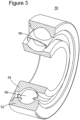
- a generic rolling bearing 50 is shown in Figure 3 .
- the rolling bearing 50 includes two races, an exterior race 52 and an interior race 54. These two races guide rolling elements 56.
- the rolling elements 56 may be balls, as shown in the figure, or may have other shapes, e.g., cylinders, etc. They may be tapered or not.
- a cage 58 may be used for keeping the rolling elements at desired distances one from the other. Other types of rolling bearings exist and are known in the art.
- the rolling bearing 50 shown in Figure 3 is traditionally lubed with synthetic oil or grease, depending on the application.
- Synthetic oil is a lubricant that includes chemical compounds which are artificially made (synthesized).
- the synthetic lubricants can be manufactured using chemically modified petroleum components rather than crude oil, but can also be synthesized from other raw materials.
- Synthetic oil is used as a substitute for lubricant refined from petroleum when operating in extreme temperature, because it generally provides superior mechanical and chemical properties than those found in traditional mineral oils.
- a generic hydro-dynamic bearing 60 includes a ring 62 that is configured to hold plural pads 64, each having a working surface 64a.
- the pads 64 are retained by a blocking plate 66 to prevent them from sliding in a rotational direction A when a shaft (not shown) rotates at high speeds inside the ring 62, in direction A.
- Corresponding retention plates 68 for preventing axial dislocation, retain the pads 64 in the proximity of the ring 62.
- Ring 62, blocking plate 66 and retention plates 68 define a predetermined volume in which pad 64 may pivot about a retaining head (not shown).
- Mineral oil is provided on the working surface 64a so that an oil film forms between the rotating shaft (not shown) and the pads 64.
- the mineral oil is a liquid by-product of the distillation of petroleum to produce gasoline and other petroleum based products from crude oil.
- the mineral oil includes mainly alkanes (typically 15 to 40 carbons) and cyclic paraffins, related to petroleum jelly (also known as "white petrolatum”).
- a turbo-compressor train is configured to have only rolling bearings and no hydro-dynamic bearings.
- the compressor in the turbo-compressor train is a centrifugal compressor, no hydro-dynamic bearings are used.
- the conventional centrifugal compressors do not use rolling bearings but only hydro-dynamic bearings.
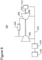
- a train 200 includes all the components shown in Figure 5 for the train 100 except that the pump 216 is not part of the train. Further, the pump 216 is not mechanically (rotational motion) connected to the train. In this exemplary embodiment, the pump is supplied with, for example, electrical power from a power source 218 (e.g., power grid or a power generator of the train). In this regard, it is noted that all the embodiments discussed in this application (e.g., Figures 5 and 8 ) have the pump mechanically connected to the train.
- a power source 218 e.g., power grid or a power generator of the train.
- the pump 116, the auxiliary gearbox 114, the compressor 102, the expander 106, and the centrifugal compressor 112 each has rolling bearings.
- a single lube pump is used and the only oil used is the synthetic oil.
- the centrifugal compressor 112 is replaced by a generator.
- the generator has rolling bearings and not hydro-dynamic bearings. Because the rolling bearings may not support enough axial trust in comparison to the hydro-dynamic bearings, a dedicated thrust balance system (developed by the assignee of this patent application) is necessary.
- a generic centrifugal compressor 140 modified as discussed above is shown in Figure 7 and is defined by the fact that air intake reaches along an X direction, at position 142, an impeller 144 and exits along a Y direction at position 146 having increased the speed of the air due to the centrifugal motion through the impeller 144.
- the impeller 144 is shown connected to the shaft 110, which is supported by the rolling bearings 148 and 150.
- piping 170 connects the lube pump 116 to each of the components of the turbo-compressor train for supplying the necessary synthetic oil.
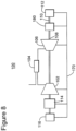
- a gearbox 180 may be provided between the shaft 108 of the expander 106 and the shaft 110 of the centrifugal compressor or generator 112. In this case, the gearbox 180 is configured to use synthetic oil and rolling bearings.
- a method for assembling a train as discussed above includes a step 900 of mechanically connecting a gas turbine engine to a centrifugal compressor; a step 902 of mechanically or electrically connecting a lube pump to the gas turbine engine; and a step 904 of providing each of the gas turbine engine, the centrifugal compressor and the lube pump only with rolling bearings and the lube pump is configured to pump synthetic oil.
- the disclosed exemplary embodiments provide a turbo-compressor and a method for providing rolling bearings to each component of the turbo-compressor. It should be understood that this description is not intended to limit the invention. On the contrary, the exemplary embodiments are intended to cover modifications, which are included in the scope of the invention as defined by the appended claims. Further, in the detailed description of the exemplary embodiments, numerous specific details are set forth in order to provide a comprehensive understanding of the claimed invention. However, one skilled in the art would understand that various embodiments may be practiced without such specific details.
Landscapes
- Engineering & Computer Science (AREA)
- Mechanical Engineering (AREA)
- General Engineering & Computer Science (AREA)
- Chemical & Material Sciences (AREA)
- Combustion & Propulsion (AREA)
- Structures Of Non-Positive Displacement Pumps (AREA)
- Rolling Contact Bearings (AREA)
- Supercharger (AREA)
Description
- The present disclosure generally relates to mechanisms and techniques for providing an entire turbo-compressor train with a single lube pump and a single lubrication oil medium.
-
EP 1 930 553 A2 discloses a gas turbine engine including a centrifugal compressor having a rotor and a thrust bearing disposed in connection with the rotor.US 4 834 622 A discloses a turbo-compressor train with a gas turbine engine, a load compressor, an accessory gearbox, a lube pump and ball bearings.DE 26 28 401 A1 discloses a gas turbine engine with an alternator using synthetic oil, ball bearings and a single oil pump.EP 1 683 943 A2 discloses a turbogenerator with a single oil pump for a gas turbine engine and a generator.US 2007/0060442 A1 discloses a turbo-compressor train with a gas turbine engine, a centrifugal compressor and an additional gearbox. - Gas turbine engines are used in many sectors of the industry, from military to power generation. They are used mainly to produce electrical energy. However, some gas turbine engines are used to propel various vehicles, airplanes, ships, etc. In the oil and gas field, the gas turbine engines are used to drive compressors, pumps and/or generators. As shown in
Figure 1 , agas turbine engine 12 may be connected to a compressor orgenerator 14 and to anauxiliary equipment 16. Agear box 18 or other equipment may be provided between thegas turbine engine 12 and the compressor orgenerator 14. All these elements form a turbo-compressor train 10. - The
gas turbine engine 12 may include acompressor 20 that is configured to receive a gas (e.g., air) at aninput 22 and to provide the gas compressed to a predetermined pressure at anoutlet 24. The compressed gas is then input to acombustor 26 where it is mixed with a fuel provided from aline 28. The mixture of gas and fuel is ignited and the hot gases at high pressure are provided to aninput 30 of anexpander 32. The exhaust gases are then released atoutput 34 of theexpander 32. - The expansion of the hot gases through the
expander 32 determines a rotation of a rotoric part (not shown) which is coupled, through thegear box 18 to a shaft of thecompressor 14. Thus, thecompressor 14 is driven by theexpander 32. One or more of the components of the turbo-compressor train 10 involves heavy rotoric parts (e.g., shaft, impeller, etc.) that rotate at a high speed. In order to promote the rotational motion of these components and to minimize the friction, various bearing units are provided in the train. A few arrangements of conventional turbo-compressor trains are discussed next. -
Figures 2A-C show thetrain 10 ofFigure 1 in which some elements have rolling bearings and the remaining elements have hydro-dynamic bearings. Those elements having the rolling bearings are identified with A and those having the hydro-dynamic bearings are identified with B. Further, it is noted that the rolling bearings need to use synthetic oil while the hydro-dynamic bearings need to use mineral oil. Thus, the arrangements shown inFigures 2A and 2B need two lube pumps, one for each type of bearings while the arrangement shown inFigure 2C uses one lube pump and the mineral oil. These arrangements have a higher weight and maintenance cost due to the dual lube pump, they have a large footprint and require higher plant complexity. A disadvantage of the configuration shown inFigure 2C is the higher lube oil consumption needed for hydrodynamic bearings. - Accordingly, it would be desirable to provide systems and methods that avoid the afore-described problems and drawbacks.
- The present invention is defined in the accompanying claims.
- The accompanying drawings, which are incorporated in and constitute a part of the specification, illustrate one or more embodiments and, together with the description, explain these embodiments. In the drawings:
-
Figure 1 is a schematic diagram of a conventional turbo-compressor train; -
Figures 2A-C are schematic diagrams of conventional turbo-compressor trains having two lube pumps or being supplied only with mineral oil; -
Figure 3 is a schematic diagram of a rolling bearing; -
Figure 4 is a schematic diagram of a hydro-dynamic bearing not forming part of the present invention; -
Figure 5 is a schematic diagram of a turbo-compressor train having a single lube pump according to an embodiment of the present invention -
Figure 6 is a schematic diagram of a turbo-compressor train having a single lube pump electrically connected to the train not forming part of the present invention; -
Figure 7 is a schematic diagram of a centrifugal compressor; -
Figure 8 is a schematic diagram of another turbo-compressor train having a single lube pump according to an embodiment of the present invention; and -
Figure 9 is a flowchart of a method for assembling a turbo-compressor train with a single lube pump according to an exemplary embodiment. - The following description of the exemplary embodiments refers to the accompanying drawings. The same reference numbers in different drawings identify the same or similar elements. The following detailed description does not limit the invention. Instead, the scope of the invention is defined by the appended claims. The following embodiments are discussed, for simplicity, with regard to the terminology and structure of a gas turbine engine system connected to a compressor or generator. However, the embodiments to be discussed next are not limited to these systems, but may be applied to other systems that have plural machines connected to each other and each machine has its own bearing system.
- Reference throughout the specification to "one embodiment" or "an embodiment" means that a particular feature, structure, or characteristic described in connection with an embodiment is included in at least one embodiment of the subject matter disclosed. Thus, the appearance of the phrases "in one embodiment" or "in an embodiment" in various places throughout the specification is not necessarily referring to the same embodiment. Further, the particular features, structures or characteristics may be combined in any suitable manner in one or more embodiments.
- According to the present invention, the components of the entire turbo-compressor train are provided with rolling bearings. Thus, no component has hydro-dynamic bearings, which is different from the traditional trains in which the compressors have hydro-dynamic bearings. In this regard, it is noted that traditional centrifugal compressors do not have rolling bearings because for this solution it is more complex to compensate the axial thrust. Moreover, the dynamic behavior of the compressor with rolling bearings is negatively influenced by the high stiffness, while the solution with hydrodynamic bearings is much more damped. In this configuration, a single lube pump is used for all the components, which results in a lower weight of the train, lower machine cost, lower footprint, and higher reliability. By removing the mineral lube oil pump for the hydro-dynamic bearings, depending on the machine, up to 250 kW of energy may be saved. Therefore, according to this configuration, all the components of the train use synthetic oil. The single lump pump is part of the train.
- Prior to discussing the arrangement of the novel train, a brief description of a rolling bearing, hydro-dynamic bearing, mineral oil and synthetic oil is believed to be in order. A generic rolling
bearing 50 is shown inFigure 3 . The rollingbearing 50 includes two races, anexterior race 52 and aninterior race 54. These two races guide rollingelements 56. The rollingelements 56 may be balls, as shown in the figure, or may have other shapes, e.g., cylinders, etc. They may be tapered or not. Acage 58 may be used for keeping the rolling elements at desired distances one from the other. Other types of rolling bearings exist and are known in the art. - The rolling
bearing 50 shown inFigure 3 is traditionally lubed with synthetic oil or grease, depending on the application. Synthetic oil is a lubricant that includes chemical compounds which are artificially made (synthesized). The synthetic lubricants can be manufactured using chemically modified petroleum components rather than crude oil, but can also be synthesized from other raw materials. Synthetic oil is used as a substitute for lubricant refined from petroleum when operating in extreme temperature, because it generally provides superior mechanical and chemical properties than those found in traditional mineral oils. - A generic hydro-
dynamic bearing 60 includes aring 62 that is configured to holdplural pads 64, each having a workingsurface 64a. Thepads 64 are retained by a blockingplate 66 to prevent them from sliding in a rotational direction A when a shaft (not shown) rotates at high speeds inside thering 62, in direction A.Corresponding retention plates 68, for preventing axial dislocation, retain thepads 64 in the proximity of thering 62.Ring 62, blockingplate 66 andretention plates 68 define a predetermined volume in whichpad 64 may pivot about a retaining head (not shown). Mineral oil is provided on the workingsurface 64a so that an oil film forms between the rotating shaft (not shown) and thepads 64. - The mineral oil is a liquid by-product of the distillation of petroleum to produce gasoline and other petroleum based products from crude oil. The mineral oil includes mainly alkanes (typically 15 to 40 carbons) and cyclic paraffins, related to petroleum jelly (also known as "white petrolatum").
- As discussed above, according to the present invention, a turbo-compressor train is configured to have only rolling bearings and no hydro-dynamic bearings. Thus, since the compressor in the turbo-compressor train is a centrifugal compressor, no hydro-dynamic bearings are used. In this regard, it is noted that the conventional centrifugal compressors do not use rolling bearings but only hydro-dynamic bearings.
-
Figure 5 shows an embodiment of a turbo-compressor train 100 according to the present invention having all components provided with rolling bearings and no hydro-dynamic bearings. The turbo-compressor train 100 includes acompressor 102 fluidly connected to acombustion chamber 104 in which fuel and air are mixed together and ignited. The hot gasses are provided to anexpander 106 whose shaft is rotated by the expansion of the hot gasses. Theexpander 106 may be an axial expander. Ashaft 108 of theexpander 106 is connected to ashaft 110 of acentrifugal compressor 112 and also to thecompressor 102. A shaft of thecompressor 102 is connected to anauxiliary gear box 114 that is configured to transmit rotational motion to a shaft of apump 116. Thepump 116 is the lube pump for the synthetic oil necessary to the rolling bearings of the various components of the turbo-compressor train. - According to a comparative example illustrated in
Figure 6 not forming part of the present invention, atrain 200 includes all the components shown inFigure 5 for thetrain 100 except that thepump 216 is not part of the train. Further, thepump 216 is not mechanically (rotational motion) connected to the train. In this exemplary embodiment, the pump is supplied with, for example, electrical power from a power source 218 (e.g., power grid or a power generator of the train). In this regard, it is noted that all the embodiments discussed in this application (e.g.,Figures 5 and8 ) have the pump mechanically connected to the train. - According to the present invention, the
pump 116, theauxiliary gearbox 114, thecompressor 102, theexpander 106, and thecentrifugal compressor 112 each has rolling bearings. Thus, according to this configuration, a single lube pump is used and the only oil used is the synthetic oil. In one application not forming part of the present invention, thecentrifugal compressor 112 is replaced by a generator. In this case, the generator has rolling bearings and not hydro-dynamic bearings. Because the rolling bearings may not support enough axial trust in comparison to the hydro-dynamic bearings, a dedicated thrust balance system (developed by the assignee of this patent application) is necessary. - A generic
centrifugal compressor 140 modified as discussed above is shown inFigure 7 and is defined by the fact that air intake reaches along an X direction, atposition 142, animpeller 144 and exits along a Y direction atposition 146 having increased the speed of the air due to the centrifugal motion through theimpeller 144. Theimpeller 144 is shown connected to theshaft 110, which is supported by the rollingbearings - Returning to
Figure 5 , it is noted that piping 170 connects thelube pump 116 to each of the components of the turbo-compressor train for supplying the necessary synthetic oil. According to an embodiment illustrated inFigure 8 , agearbox 180 may be provided between theshaft 108 of theexpander 106 and theshaft 110 of the centrifugal compressor orgenerator 112. In this case, thegearbox 180 is configured to use synthetic oil and rolling bearings. - According to an exemplary embodiment illustrated in
Figure 9 , a method for assembling a train as discussed above is not described. The method includes astep 900 of mechanically connecting a gas turbine engine to a centrifugal compressor; astep 902 of mechanically or electrically connecting a lube pump to the gas turbine engine; and astep 904 of providing each of the gas turbine engine, the centrifugal compressor and the lube pump only with rolling bearings and the lube pump is configured to pump synthetic oil. - The disclosed exemplary embodiments provide a turbo-compressor and a method for providing rolling bearings to each component of the turbo-compressor. It should be understood that this description is not intended to limit the invention. On the contrary, the exemplary embodiments are intended to cover modifications, which are included in the scope of the invention as defined by the appended claims. Further, in the detailed description of the exemplary embodiments, numerous specific details are set forth in order to provide a comprehensive understanding of the claimed invention. However, one skilled in the art would understand that various embodiments may be practiced without such specific details.
- This written description uses examples of the subject matter disclosed to enable any person skilled in the art to practice the same. The patentable scope of the subject matter is defined by the claims.
Claims (4)
- A turbo-compressor train (100) for use in the oil and gas field industry to drive a compressor, the train comprising a gas turbine engine (102, 104, 106), a centrifugal compressor (112), an auxiliary gearbox (114), a lube pump (116), a bearing system and a thrust balance system,the gas turbine engine including a compressor (102) fluidly connected to a combustion chamber (104) in which fuel and air are mixed together and ignited, the hot gases being provided to an expander (106), the gas turbine engine (102, 104, 106) configured to transform thermal energy into mechanical energy, andthe centrifugal compressor (112) having a shaft (110) connected to a shaft (108) of the expander (106),characterized in thatthe lube pump is a single lube pump (116) connected to oil piping (170) and configured to provide synthetic oil to the gas turbine engine (102, 104, 106), the centrifugal compressor (112) and the auxiliary gearbox (114),the auxiliary gearbox (114) connecting a shaft of the compressor (102) to a shaft of the lube pump (116), and the auxiliary gearbox (114) is configured to work with synthetic oil, andthe bearing system of the entire turbo-compressor train (100) being provided with rolling bearings, wherein no component of the train (100) has hydro-dynamic bearings and no mineral oil is used in any component of the train (100),wherein the bearings of the gas turbine engine (102, 104, 106), the centrifugal compressor (112), the single lube pump (116) and the auxiliary gearbox (114) each comprise only rolling bearings configured to be lubricated by the synthetic oil provided by the single lube pump (116); andwherein the thrust balance system is configured to compensate axial thrust in the turbo-compressor train (100).
- The train of claim 1, wherein the gas turbine engine (102, 104, 106) includes an axial expander (106).
- The train of any preceding claim, further comprising: a gearbox (180) configured to mechanically connect the shaft (108) of the expander (106) and the shaft (110) of the centrifugal compressor (112).
- A method for assembling a turbo-compressor train (100) for use in the oil and gas field industry as claimed in any preceding claim, the method comprising:mechanically connecting the shaft (108) of the expander (106) to the shaft (110) of the centrifugal compressor (112);mechanically connecting via the auxiliary gearbox (114) the shaft of the single lube pump (116) to the shaft of the compressor (102); andproviding each of the gas turbine engine (102, 104, 106), the centrifugal compressor (112), the single lube pump (116) and the auxiliary gearbox (114) only with rolling bearings configured to be lubricated by the synthetic oil provided by the single lube pump (116).
Applications Claiming Priority (2)
| Application Number | Priority Date | Filing Date | Title |
|---|---|---|---|
| IT000031A ITCO20110031A1 (en) | 2011-07-28 | 2011-07-28 | TRAIN OF TURBOCHARGERS WITH ROTATING SUPPORTS AND METHOD |
| PCT/EP2012/064615 WO2013014198A1 (en) | 2011-07-28 | 2012-07-25 | Turbo - compressor train with rolling bearings and related assembly method |
Publications (2)
| Publication Number | Publication Date |
|---|---|
| EP2737191A1 EP2737191A1 (en) | 2014-06-04 |
| EP2737191B1 true EP2737191B1 (en) | 2024-09-11 |
Family
ID=44675665
Family Applications (1)
| Application Number | Title | Priority Date | Filing Date |
|---|---|---|---|
| EP12740578.5A Active EP2737191B1 (en) | 2011-07-28 | 2012-07-25 | Turbo-compressor train with rolling bearings and single lube pump |
Country Status (12)
| Country | Link |
|---|---|
| US (1) | US20140157750A1 (en) |
| EP (1) | EP2737191B1 (en) |
| JP (2) | JP2014521862A (en) |
| KR (1) | KR101941320B1 (en) |
| CN (1) | CN103717856B (en) |
| AU (1) | AU2012288836B2 (en) |
| BR (1) | BR112014001115B1 (en) |
| CA (1) | CA2843112C (en) |
| ES (1) | ES2991985T3 (en) |
| IT (1) | ITCO20110031A1 (en) |
| RU (1) | RU2623058C2 (en) |
| WO (1) | WO2013014198A1 (en) |
Families Citing this family (9)
| Publication number | Priority date | Publication date | Assignee | Title |
|---|---|---|---|---|
| ITCO20130043A1 (en) * | 2013-10-02 | 2015-04-03 | Nuovo Pignone Srl | METHOD AND SYSTEM TO MONITOR THE FUNCTIONING OF A FLEXIBLE COUPLING DEVICE |
| FR3014543B1 (en) * | 2013-12-06 | 2018-11-09 | L'air Liquide, Societe Anonyme Pour L'etude Et L'exploitation Des Procedes Georges Claude | LOW TEMPERATURE COOLING AND / OR LIQUEFACTION DEVICE AND METHOD |
| ITUB20155049A1 (en) | 2015-10-20 | 2017-04-20 | Nuovo Pignone Tecnologie Srl | INTEGRATED TRAIN OF POWER GENERATION AND COMPRESSION, AND METHOD |
| FR3049006B1 (en) * | 2016-03-15 | 2018-03-16 | Safran Aircraft Engines | TURBOREACTOR HAVING A SIMPLIFIED BEARING LUBRICATION GROUP |
| FR3049007B1 (en) * | 2016-03-15 | 2019-05-10 | Safran Aircraft Engines | TURBOREACTOR HAVING A SIMPLIFIED BEARING LUBRICATION GROUP |
| IT201700008681A1 (en) * | 2017-01-26 | 2018-07-26 | Nuovo Pignone Tecnologie Srl | GAS TURBINE SYSTEM |
| JP2019017926A (en) * | 2017-07-21 | 2019-02-07 | 株式会社三洋物産 | Game machine |
| US11187437B2 (en) | 2019-01-09 | 2021-11-30 | Heatcraft Refrigeration Products Llc | Cooling system |
| CN119712614B (en) * | 2025-03-03 | 2025-05-27 | 盈德气体工程(浙江)有限公司 | Interface structure of centrifugal compressor and diffuser |
Citations (8)
| Publication number | Priority date | Publication date | Assignee | Title |
|---|---|---|---|---|
| US3216712A (en) * | 1962-08-15 | 1965-11-09 | United Aircraft Corp | Air supply for a blast furnace |
| US3687233A (en) * | 1970-07-23 | 1972-08-29 | Garrett Corp | Integral lubrication system |
| JPS61187539A (en) * | 1985-02-15 | 1986-08-21 | Hitachi Ltd | Gas turbine equipped with shaft driven fuel gas compressor |
| US20050279102A1 (en) * | 2004-06-17 | 2005-12-22 | Pratt & Whitney Canada Corp. | Modulated current gas turbine engine starting system |
| EP1683943A2 (en) * | 2004-12-23 | 2006-07-26 | NUOVO PIGNONE S.p.A. | Turbogenerator |
| EP1722074A2 (en) * | 2005-05-06 | 2006-11-15 | General Electric Company | Lubrication system for a gas turbine engine and corresponding gas turbine |
| US20070060442A1 (en) * | 2005-09-14 | 2007-03-15 | Ransbarger Weldon L | Rotation coupling employing torque converter and synchronization motor |
| US7452181B2 (en) * | 2005-01-28 | 2008-11-18 | Hitachi, Ltd. | Plant facility |
Family Cites Families (38)
| Publication number | Priority date | Publication date | Assignee | Title |
|---|---|---|---|---|
| US3170292A (en) * | 1960-04-04 | 1965-02-23 | Ford Motor Co | Lubricating system for a gas turbine engine |
| US3722212A (en) * | 1971-03-04 | 1973-03-27 | Avco Corp | Gas turbine engine lubrication system |
| JPS5211313A (en) * | 1975-06-24 | 1977-01-28 | Deere & Co | Gas turbine engine |
| FR2475656A1 (en) * | 1980-02-12 | 1981-08-14 | Snecma | ROLLER BEARING COMPRISING A LUBRING DEVICE FOR THE INNER BEARING TRACK |
| US4431372A (en) * | 1980-07-01 | 1984-02-14 | Westinghouse Electric Corp. | Method and apparatus for lubricating turbine bearings |
| DE3461398D1 (en) * | 1983-04-29 | 1987-01-08 | Bbc Brown Boveri & Cie | Self-priming centrifugal lubrication pump for a turbo charger |
| US4834622A (en) * | 1983-06-15 | 1989-05-30 | Sundstrand Corporation | Gas turbine engine/load compressor power plants |
| US4627234A (en) * | 1983-06-15 | 1986-12-09 | Sundstrand Corporation | Gas turbine engine/load compressor power plants |
| JPH0740777B2 (en) * | 1984-11-19 | 1995-05-01 | トヨタ自動車株式会社 | High speed generator for gas turbine |
| JPS61226524A (en) * | 1985-03-29 | 1986-10-08 | Nissan Motor Co Ltd | Turbosupercharger |
| JPS6453023A (en) * | 1987-08-18 | 1989-03-01 | Suntory Ltd | Steam recycling system in beer malt juice boiling process |
| IT239879Y1 (en) * | 1996-12-23 | 2001-03-13 | Elasis Sistema Ricerca Fiat | REFINEMENTS TO A PISTON PUMP, IN PARTICULAR TO A RADIAL APISTON PUMP FOR THE FUEL OF AN INTERNAL COMBUSTION ENGINE. |
| GB2410380B (en) * | 2000-11-30 | 2005-08-31 | Richard Julius Gozdawa | Rotor for electric generator or motor |
| DE10122695A1 (en) * | 2001-05-10 | 2002-11-21 | Siemens Ag | Process for cooling a gas turbine and gas turbine plant |
| DE10138056A1 (en) * | 2001-08-03 | 2003-02-13 | Atlas Copco Energas | turbomachinery |
| SE521349C2 (en) * | 2001-12-14 | 2003-10-21 | Atlas Copco Tools Ab | Compressor unit with control system |
| US7462948B2 (en) * | 2003-03-06 | 2008-12-09 | Thinktank Phoenix Co., Ltd. | Midget gas turbine |
| GB2410982A (en) * | 2004-02-14 | 2005-08-17 | Richard Julius Gozdawa | Turbomachinery electric generator arrangement with component cooling |
| US7296398B2 (en) * | 2004-10-29 | 2007-11-20 | General Electric Company | Counter-rotating turbine engine and method of assembling same |
| JP4349314B2 (en) * | 2005-04-22 | 2009-10-21 | トヨタ自動車株式会社 | Thrust adjustment device |
| US7805947B2 (en) * | 2005-05-19 | 2010-10-05 | Djamal Moulebhar | Aircraft with disengageable engine and auxiliary power unit components |
| DE102005054088A1 (en) * | 2005-11-12 | 2007-05-16 | Mtu Aero Engines Gmbh | planetary gear |
| US7641457B2 (en) * | 2006-03-28 | 2010-01-05 | Jtekt Corporation | Internal gear pump |
| US7743600B2 (en) * | 2006-04-04 | 2010-06-29 | United Technologies Corporation | Gas turbine engine telemetry module |
| US7621117B2 (en) * | 2006-06-19 | 2009-11-24 | Pratt & Whitney Canada Corp. | Apparatus and method for controlling engine windmilling |
| US8424646B2 (en) * | 2006-07-10 | 2013-04-23 | United Technologies Corporation | Interruption tolerant lubrication system |
| US7815417B2 (en) * | 2006-09-01 | 2010-10-19 | United Technologies Corporation | Guide vane for a gas turbine engine |
| US7824151B2 (en) * | 2006-12-06 | 2010-11-02 | United Technologies Corporation | Zero running clearance centrifugal compressor |
| JP5135969B2 (en) * | 2007-09-25 | 2013-02-06 | 株式会社ジェイテクト | Turbocharger |
| US20130004291A1 (en) * | 2011-06-28 | 2013-01-03 | Williams International Co., L.L.C. | Turbomachine Fluid-Conduit Housing Coupling System and Method |
| JP5314517B2 (en) * | 2009-07-06 | 2013-10-16 | 三菱重工業株式会社 | Bearing device, bearing unit and rotating machine |
| DE102009053102B4 (en) * | 2009-11-13 | 2013-03-28 | Continental Automotive Gmbh | Turbocharger having a thrust bearing arrangement for a shaft of the turbocharger |
| RU93462U1 (en) * | 2009-12-17 | 2010-04-27 | Государственное образовательное учреждение высшего профессионального образования "Саратовский государственный технический университет" (СГТУ) | LUBRICATION SYSTEM OF THE TURBOCHARGER OF THE INTERNAL COMBUSTION ENGINE |
| IT1397707B1 (en) * | 2009-12-22 | 2013-01-24 | Nuovo Pignone Spa | DYNAMIC BALANCE OF PUSHING FOR CENTRIFUGAL COMPRESSORS. |
| US20130091859A1 (en) * | 2011-10-17 | 2013-04-18 | Omar I. Osorio | Auxiliary power unit fluid system fluid control |
| DE102011086674A1 (en) * | 2011-11-18 | 2013-05-23 | Rolls-Royce Deutschland Ltd & Co Kg | Storage device and turbomachinery with storage device |
| US9441541B2 (en) * | 2012-04-27 | 2016-09-13 | General Electric Company | Oil scoop manifold |
| US20160047308A1 (en) * | 2014-08-15 | 2016-02-18 | General Electric Company | Mechanical drive architectures with low-loss lubricant bearings and low-density materials |
-
2011
- 2011-07-28 IT IT000031A patent/ITCO20110031A1/en unknown
-
2012
- 2012-07-25 WO PCT/EP2012/064615 patent/WO2013014198A1/en not_active Ceased
- 2012-07-25 AU AU2012288836A patent/AU2012288836B2/en active Active
- 2012-07-25 EP EP12740578.5A patent/EP2737191B1/en active Active
- 2012-07-25 ES ES12740578T patent/ES2991985T3/en active Active
- 2012-07-25 JP JP2014522082A patent/JP2014521862A/en active Pending
- 2012-07-25 KR KR1020147002117A patent/KR101941320B1/en active Active
- 2012-07-25 CN CN201280037895.5A patent/CN103717856B/en active Active
- 2012-07-25 US US14/235,228 patent/US20140157750A1/en not_active Abandoned
- 2012-07-25 CA CA2843112A patent/CA2843112C/en active Active
- 2012-07-25 RU RU2014100848A patent/RU2623058C2/en active
- 2012-07-25 BR BR112014001115-0A patent/BR112014001115B1/en active IP Right Grant
-
2017
- 2017-02-28 JP JP2017035729A patent/JP6462024B2/en active Active
Patent Citations (8)
| Publication number | Priority date | Publication date | Assignee | Title |
|---|---|---|---|---|
| US3216712A (en) * | 1962-08-15 | 1965-11-09 | United Aircraft Corp | Air supply for a blast furnace |
| US3687233A (en) * | 1970-07-23 | 1972-08-29 | Garrett Corp | Integral lubrication system |
| JPS61187539A (en) * | 1985-02-15 | 1986-08-21 | Hitachi Ltd | Gas turbine equipped with shaft driven fuel gas compressor |
| US20050279102A1 (en) * | 2004-06-17 | 2005-12-22 | Pratt & Whitney Canada Corp. | Modulated current gas turbine engine starting system |
| EP1683943A2 (en) * | 2004-12-23 | 2006-07-26 | NUOVO PIGNONE S.p.A. | Turbogenerator |
| US7452181B2 (en) * | 2005-01-28 | 2008-11-18 | Hitachi, Ltd. | Plant facility |
| EP1722074A2 (en) * | 2005-05-06 | 2006-11-15 | General Electric Company | Lubrication system for a gas turbine engine and corresponding gas turbine |
| US20070060442A1 (en) * | 2005-09-14 | 2007-03-15 | Ransbarger Weldon L | Rotation coupling employing torque converter and synchronization motor |
Also Published As
| Publication number | Publication date |
|---|---|
| ITCO20110031A1 (en) | 2013-01-29 |
| US20140157750A1 (en) | 2014-06-12 |
| RU2623058C2 (en) | 2017-06-21 |
| AU2012288836B2 (en) | 2016-09-08 |
| RU2014100848A (en) | 2015-09-10 |
| KR101941320B1 (en) | 2019-01-22 |
| CA2843112A1 (en) | 2013-01-31 |
| CN103717856A (en) | 2014-04-09 |
| ES2991985T3 (en) | 2024-12-05 |
| AU2012288836A1 (en) | 2014-02-06 |
| JP6462024B2 (en) | 2019-01-30 |
| EP2737191A1 (en) | 2014-06-04 |
| BR112014001115B1 (en) | 2021-01-19 |
| JP2017141835A (en) | 2017-08-17 |
| JP2014521862A (en) | 2014-08-28 |
| WO2013014198A1 (en) | 2013-01-31 |
| KR20140044378A (en) | 2014-04-14 |
| BR112014001115A2 (en) | 2017-02-14 |
| CN103717856B (en) | 2017-06-27 |
| CA2843112C (en) | 2020-01-21 |
Similar Documents
| Publication | Publication Date | Title |
|---|---|---|
| CA2843112C (en) | Turbo-compressor train with rolling bearings and related assembly method | |
| US7500365B2 (en) | Accessory gearbox | |
| US9062611B2 (en) | Split accessory drive system | |
| Gritsenko et al. | Development of combined ICE startup system by means of hydraulic starter | |
| US10711642B2 (en) | Gas turbine engine lubrication system and apparatus with boost pump system | |
| US20060107647A1 (en) | Turbine, particularly useful for small aircraft | |
| US20170298830A1 (en) | Oil-free gas turbine engine | |
| US6881027B2 (en) | Gearless/oilless gas turbine engine | |
| US10145260B2 (en) | Accessory drive case for a turboprop | |
| US9097186B2 (en) | Bevel gear arrangement for axial accessory gearbox | |
| EP2964928A1 (en) | Non-contacting seals for geared gas turbine engine bearing compartments | |
| EP3502499A1 (en) | Fuel lubricated foil bearing | |
| US9726037B2 (en) | Bearing systems for turbochargers used on internal combustion engines | |
| US20190010841A1 (en) | Engine transportation apparatus | |
| US10670077B2 (en) | Sealed bearing assembly and method of forming same | |
| MX2014001151A (en) | Turbo - compressor train with rolling bearings and related assembly method. | |
| Bruckner | A Propulsion System Analysis of Oil Free Turbomachinery for Aviation Turbofan Engines | |
| RU2711895C2 (en) | Double-flow jet turbine engine | |
| US9540952B2 (en) | Turbocharger with oil-free hydrostatic bearing | |
| Sato et al. | Design, Analysis, and Tests of Differential Planetary Gear System for Open Rotor Power Gearbox | |
| CN121175482A (en) | Turbine engine comprising an accessory drive, a lubrication unit and an oil tank | |
| Linn | Lubrication Problems and Requirements of Gas Turbine Equipment | |
| Buss | Running on air... bearings | |
| Howe et al. | Design of a gear drive for counter-rotating fan rotors |
Legal Events
| Date | Code | Title | Description |
|---|---|---|---|
| PUAI | Public reference made under article 153(3) epc to a published international application that has entered the european phase |
Free format text: ORIGINAL CODE: 0009012 |
|
| 17P | Request for examination filed |
Effective date: 20140228 |
|
| AK | Designated contracting states |
Kind code of ref document: A1 Designated state(s): AL AT BE BG CH CY CZ DE DK EE ES FI FR GB GR HR HU IE IS IT LI LT LU LV MC MK MT NL NO PL PT RO RS SE SI SK SM TR |
|
| DAX | Request for extension of the european patent (deleted) | ||
| STAA | Information on the status of an ep patent application or granted ep patent |
Free format text: STATUS: EXAMINATION IS IN PROGRESS |
|
| 17Q | First examination report despatched |
Effective date: 20180516 |
|
| P01 | Opt-out of the competence of the unified patent court (upc) registered |
Effective date: 20230526 |
|
| GRAP | Despatch of communication of intention to grant a patent |
Free format text: ORIGINAL CODE: EPIDOSNIGR1 |
|
| STAA | Information on the status of an ep patent application or granted ep patent |
Free format text: STATUS: GRANT OF PATENT IS INTENDED |
|
| INTG | Intention to grant announced |
Effective date: 20240209 |
|
| GRAS | Grant fee paid |
Free format text: ORIGINAL CODE: EPIDOSNIGR3 |
|
| GRAA | (expected) grant |
Free format text: ORIGINAL CODE: 0009210 |
|
| STAA | Information on the status of an ep patent application or granted ep patent |
Free format text: STATUS: THE PATENT HAS BEEN GRANTED |
|
| AK | Designated contracting states |
Kind code of ref document: B1 Designated state(s): AL AT BE BG CH CY CZ DE DK EE ES FI FR GB GR HR HU IE IS IT LI LT LU LV MC MK MT NL NO PL PT RO RS SE SI SK SM TR |
|
| REG | Reference to a national code |
Ref country code: GB Ref legal event code: FG4D |
|
| REG | Reference to a national code |
Ref country code: CH Ref legal event code: EP |
|
| REG | Reference to a national code |
Ref country code: DE Ref legal event code: R096 Ref document number: 602012081061 Country of ref document: DE |
|
| REG | Reference to a national code |
Ref country code: IE Ref legal event code: FG4D |
|
| REG | Reference to a national code |
Ref country code: ES Ref legal event code: FG2A Ref document number: 2991985 Country of ref document: ES Kind code of ref document: T3 Effective date: 20241205 |
|
| REG | Reference to a national code |
Ref country code: LT Ref legal event code: MG9D |
|
| REG | Reference to a national code |
Ref country code: NL Ref legal event code: MP Effective date: 20240911 |
|
| PG25 | Lapsed in a contracting state [announced via postgrant information from national office to epo] |
Ref country code: GR Free format text: LAPSE BECAUSE OF FAILURE TO SUBMIT A TRANSLATION OF THE DESCRIPTION OR TO PAY THE FEE WITHIN THE PRESCRIBED TIME-LIMIT Effective date: 20241212 Ref country code: FI Free format text: LAPSE BECAUSE OF FAILURE TO SUBMIT A TRANSLATION OF THE DESCRIPTION OR TO PAY THE FEE WITHIN THE PRESCRIBED TIME-LIMIT Effective date: 20240911 |
|
| PG25 | Lapsed in a contracting state [announced via postgrant information from national office to epo] |
Ref country code: BG Free format text: LAPSE BECAUSE OF FAILURE TO SUBMIT A TRANSLATION OF THE DESCRIPTION OR TO PAY THE FEE WITHIN THE PRESCRIBED TIME-LIMIT Effective date: 20240911 |
|
| PG25 | Lapsed in a contracting state [announced via postgrant information from national office to epo] |
Ref country code: LV Free format text: LAPSE BECAUSE OF FAILURE TO SUBMIT A TRANSLATION OF THE DESCRIPTION OR TO PAY THE FEE WITHIN THE PRESCRIBED TIME-LIMIT Effective date: 20240911 |
|
| PG25 | Lapsed in a contracting state [announced via postgrant information from national office to epo] |
Ref country code: HR Free format text: LAPSE BECAUSE OF FAILURE TO SUBMIT A TRANSLATION OF THE DESCRIPTION OR TO PAY THE FEE WITHIN THE PRESCRIBED TIME-LIMIT Effective date: 20240911 |
|
| PG25 | Lapsed in a contracting state [announced via postgrant information from national office to epo] |
Ref country code: RS Free format text: LAPSE BECAUSE OF FAILURE TO SUBMIT A TRANSLATION OF THE DESCRIPTION OR TO PAY THE FEE WITHIN THE PRESCRIBED TIME-LIMIT Effective date: 20241211 |
|
| PG25 | Lapsed in a contracting state [announced via postgrant information from national office to epo] |
Ref country code: RS Free format text: LAPSE BECAUSE OF FAILURE TO SUBMIT A TRANSLATION OF THE DESCRIPTION OR TO PAY THE FEE WITHIN THE PRESCRIBED TIME-LIMIT Effective date: 20241211 Ref country code: LV Free format text: LAPSE BECAUSE OF FAILURE TO SUBMIT A TRANSLATION OF THE DESCRIPTION OR TO PAY THE FEE WITHIN THE PRESCRIBED TIME-LIMIT Effective date: 20240911 Ref country code: HR Free format text: LAPSE BECAUSE OF FAILURE TO SUBMIT A TRANSLATION OF THE DESCRIPTION OR TO PAY THE FEE WITHIN THE PRESCRIBED TIME-LIMIT Effective date: 20240911 Ref country code: GR Free format text: LAPSE BECAUSE OF FAILURE TO SUBMIT A TRANSLATION OF THE DESCRIPTION OR TO PAY THE FEE WITHIN THE PRESCRIBED TIME-LIMIT Effective date: 20241212 Ref country code: FI Free format text: LAPSE BECAUSE OF FAILURE TO SUBMIT A TRANSLATION OF THE DESCRIPTION OR TO PAY THE FEE WITHIN THE PRESCRIBED TIME-LIMIT Effective date: 20240911 Ref country code: BG Free format text: LAPSE BECAUSE OF FAILURE TO SUBMIT A TRANSLATION OF THE DESCRIPTION OR TO PAY THE FEE WITHIN THE PRESCRIBED TIME-LIMIT Effective date: 20240911 |
|
| REG | Reference to a national code |
Ref country code: AT Ref legal event code: MK05 Ref document number: 1722861 Country of ref document: AT Kind code of ref document: T Effective date: 20240911 |
|
| PG25 | Lapsed in a contracting state [announced via postgrant information from national office to epo] |
Ref country code: NL Free format text: LAPSE BECAUSE OF FAILURE TO SUBMIT A TRANSLATION OF THE DESCRIPTION OR TO PAY THE FEE WITHIN THE PRESCRIBED TIME-LIMIT Effective date: 20240911 |
|
| PG25 | Lapsed in a contracting state [announced via postgrant information from national office to epo] |
Ref country code: PT Free format text: LAPSE BECAUSE OF FAILURE TO SUBMIT A TRANSLATION OF THE DESCRIPTION OR TO PAY THE FEE WITHIN THE PRESCRIBED TIME-LIMIT Effective date: 20250113 Ref country code: IS Free format text: LAPSE BECAUSE OF FAILURE TO SUBMIT A TRANSLATION OF THE DESCRIPTION OR TO PAY THE FEE WITHIN THE PRESCRIBED TIME-LIMIT Effective date: 20250111 |
|
| PG25 | Lapsed in a contracting state [announced via postgrant information from national office to epo] |
Ref country code: SM Free format text: LAPSE BECAUSE OF FAILURE TO SUBMIT A TRANSLATION OF THE DESCRIPTION OR TO PAY THE FEE WITHIN THE PRESCRIBED TIME-LIMIT Effective date: 20240911 Ref country code: RO Free format text: LAPSE BECAUSE OF FAILURE TO SUBMIT A TRANSLATION OF THE DESCRIPTION OR TO PAY THE FEE WITHIN THE PRESCRIBED TIME-LIMIT Effective date: 20240911 |
|
| PG25 | Lapsed in a contracting state [announced via postgrant information from national office to epo] |
Ref country code: EE Free format text: LAPSE BECAUSE OF FAILURE TO SUBMIT A TRANSLATION OF THE DESCRIPTION OR TO PAY THE FEE WITHIN THE PRESCRIBED TIME-LIMIT Effective date: 20240911 Ref country code: AT Free format text: LAPSE BECAUSE OF FAILURE TO SUBMIT A TRANSLATION OF THE DESCRIPTION OR TO PAY THE FEE WITHIN THE PRESCRIBED TIME-LIMIT Effective date: 20240911 |
|
| PG25 | Lapsed in a contracting state [announced via postgrant information from national office to epo] |
Ref country code: PL Free format text: LAPSE BECAUSE OF FAILURE TO SUBMIT A TRANSLATION OF THE DESCRIPTION OR TO PAY THE FEE WITHIN THE PRESCRIBED TIME-LIMIT Effective date: 20240911 Ref country code: CZ Free format text: LAPSE BECAUSE OF FAILURE TO SUBMIT A TRANSLATION OF THE DESCRIPTION OR TO PAY THE FEE WITHIN THE PRESCRIBED TIME-LIMIT Effective date: 20240911 |
|
| PG25 | Lapsed in a contracting state [announced via postgrant information from national office to epo] |
Ref country code: SK Free format text: LAPSE BECAUSE OF FAILURE TO SUBMIT A TRANSLATION OF THE DESCRIPTION OR TO PAY THE FEE WITHIN THE PRESCRIBED TIME-LIMIT Effective date: 20240911 Ref country code: IT Free format text: LAPSE BECAUSE OF FAILURE TO SUBMIT A TRANSLATION OF THE DESCRIPTION OR TO PAY THE FEE WITHIN THE PRESCRIBED TIME-LIMIT Effective date: 20240911 |
|
| REG | Reference to a national code |
Ref country code: DE Ref legal event code: R097 Ref document number: 602012081061 Country of ref document: DE |
|
| PG25 | Lapsed in a contracting state [announced via postgrant information from national office to epo] |
Ref country code: DK Free format text: LAPSE BECAUSE OF FAILURE TO SUBMIT A TRANSLATION OF THE DESCRIPTION OR TO PAY THE FEE WITHIN THE PRESCRIBED TIME-LIMIT Effective date: 20240911 |
|
| PGFP | Annual fee paid to national office [announced via postgrant information from national office to epo] |
Ref country code: GB Payment date: 20250619 Year of fee payment: 14 |
|
| PGFP | Annual fee paid to national office [announced via postgrant information from national office to epo] |
Ref country code: NO Payment date: 20250623 Year of fee payment: 14 |
|
| PGFP | Annual fee paid to national office [announced via postgrant information from national office to epo] |
Ref country code: FR Payment date: 20250620 Year of fee payment: 14 |
|
| PLBE | No opposition filed within time limit |
Free format text: ORIGINAL CODE: 0009261 |
|
| STAA | Information on the status of an ep patent application or granted ep patent |
Free format text: STATUS: NO OPPOSITION FILED WITHIN TIME LIMIT |
|
| 26N | No opposition filed |
Effective date: 20250612 |
|
| PG25 | Lapsed in a contracting state [announced via postgrant information from national office to epo] |
Ref country code: SE Free format text: LAPSE BECAUSE OF FAILURE TO SUBMIT A TRANSLATION OF THE DESCRIPTION OR TO PAY THE FEE WITHIN THE PRESCRIBED TIME-LIMIT Effective date: 20240911 |
|
| PGFP | Annual fee paid to national office [announced via postgrant information from national office to epo] |
Ref country code: ES Payment date: 20250801 Year of fee payment: 14 |
|
| PGFP | Annual fee paid to national office [announced via postgrant information from national office to epo] |
Ref country code: DE Payment date: 20250620 Year of fee payment: 14 |
|
| PGFP | Annual fee paid to national office [announced via postgrant information from national office to epo] |
Ref country code: CH Payment date: 20250801 Year of fee payment: 14 |
|
| PG25 | Lapsed in a contracting state [announced via postgrant information from national office to epo] |
Ref country code: LU Free format text: LAPSE BECAUSE OF NON-PAYMENT OF DUE FEES Effective date: 20250725 |
|
| REG | Reference to a national code |
Ref country code: BE Ref legal event code: MM Effective date: 20250731 |
|
| PG25 | Lapsed in a contracting state [announced via postgrant information from national office to epo] |
Ref country code: BE Free format text: LAPSE BECAUSE OF NON-PAYMENT OF DUE FEES Effective date: 20250731 |