EP2736675B1 - Modular dual-action device - Google Patents
Modular dual-action device Download PDFInfo
- Publication number
- EP2736675B1 EP2736675B1 EP12740832.6A EP12740832A EP2736675B1 EP 2736675 B1 EP2736675 B1 EP 2736675B1 EP 12740832 A EP12740832 A EP 12740832A EP 2736675 B1 EP2736675 B1 EP 2736675B1
- Authority
- EP
- European Patent Office
- Prior art keywords
- module
- backing plate
- spindle
- housing
- pad
- Prior art date
- Legal status (The legal status is an assumption and is not a legal conclusion. Google has not performed a legal analysis and makes no representation as to the accuracy of the status listed.)
- Active
Links
Images



Classifications
-
- B—PERFORMING OPERATIONS; TRANSPORTING
- B24—GRINDING; POLISHING
- B24B—MACHINES, DEVICES, OR PROCESSES FOR GRINDING OR POLISHING; DRESSING OR CONDITIONING OF ABRADING SURFACES; FEEDING OF GRINDING, POLISHING, OR LAPPING AGENTS
- B24B41/00—Component parts such as frames, beds, carriages, headstocks
- B24B41/04—Headstocks; Working-spindles; Features relating thereto
- B24B41/047—Grinding heads for working on plane surfaces
-
- B—PERFORMING OPERATIONS; TRANSPORTING
- B24—GRINDING; POLISHING
- B24B—MACHINES, DEVICES, OR PROCESSES FOR GRINDING OR POLISHING; DRESSING OR CONDITIONING OF ABRADING SURFACES; FEEDING OF GRINDING, POLISHING, OR LAPPING AGENTS
- B24B23/00—Portable grinding machines, e.g. hand-guided; Accessories therefor
- B24B23/02—Portable grinding machines, e.g. hand-guided; Accessories therefor with rotating grinding tools; Accessories therefor
- B24B23/022—Spindle-locking devices, e.g. for mounting or removing the tool
-
- B—PERFORMING OPERATIONS; TRANSPORTING
- B24—GRINDING; POLISHING
- B24B—MACHINES, DEVICES, OR PROCESSES FOR GRINDING OR POLISHING; DRESSING OR CONDITIONING OF ABRADING SURFACES; FEEDING OF GRINDING, POLISHING, OR LAPPING AGENTS
- B24B23/00—Portable grinding machines, e.g. hand-guided; Accessories therefor
- B24B23/02—Portable grinding machines, e.g. hand-guided; Accessories therefor with rotating grinding tools; Accessories therefor
- B24B23/03—Portable grinding machines, e.g. hand-guided; Accessories therefor with rotating grinding tools; Accessories therefor the tool being driven in a combined movement
-
- B—PERFORMING OPERATIONS; TRANSPORTING
- B24—GRINDING; POLISHING
- B24B—MACHINES, DEVICES, OR PROCESSES FOR GRINDING OR POLISHING; DRESSING OR CONDITIONING OF ABRADING SURFACES; FEEDING OF GRINDING, POLISHING, OR LAPPING AGENTS
- B24B47/00—Drives or gearings; Equipment therefor
- B24B47/10—Drives or gearings; Equipment therefor for rotating or reciprocating working-spindles carrying grinding wheels or workpieces
- B24B47/12—Drives or gearings; Equipment therefor for rotating or reciprocating working-spindles carrying grinding wheels or workpieces by mechanical gearing or electric power
Definitions
- Modular devices are provided for processing a substrate. More particularly, modular devices are provided for performing orbital rotation (dual-action) processing on a substrate.
- Rotary sanders, grinders, polishers, buffers, and cleaners are used in a wide range of applications, including carpentry, metal working, vehicle detailing, and vehicle repair. These tools can also be used with diverse substrates, including marble, glass, upholstery, wood, metal and painted surfaces. The tools are sometimes adapted for specialized applications, for example when there is risk of damaging the substrate.
- One such application is in automotive and marine exterior detailing.
- Car exteriors typically include several layers of paint, which are then topped with a protective clear coat layer.
- Boats typically utilize a gel coat in lieu of the protective clear coat layer that may be treated in a similar fashion to automotive finishes.
- car enthusiasts apply a wax or liquid polish composition to the exterior of the car and then use a rotary polisher to spread the composition and remove swirls and minor scratches from the clear coat layer.
- Simple rotary (or "single-action") polishers use a work member that rapidly spins about a fixed axis of rotation relative to the polishing device. While these devices are capable of polishing the substrate at a high cut rates, this action can also generate significant heat because the polishing head rotates at such high speeds. In the hands of an untrained operator, a single-action polisher can generate enough heat to risk "burning" the paint, which refers to the undesirable removal of paint residing below the clear coat surface. Decreasing the rotational speed of the work member can reduce this risk, but doing so can also reduce polishing efficiency below acceptable levels.
- Dual action polishers use a work member that spins about a central spindle, while the spindle itself rotates around an eccentric offset. Like a planet orbiting around the sun, the head of a dual-action polisher spins about a first axis while orbiting around a second axis displaced from the first axis. For this reason, these dual-action devices are also sometimes referred to as orbital polishers.
- the combined rotating/orbiting motion dissipates heat and can effectively prevent the polisher from burning the paint. This safety feature makes dual-action devices an attractive option for hobbyists and professionals alike.
- GB 677 518 A relates to a mounting for an eccentrically driven rubbing head of a rubbing attachment for an electric hand drilling machine.
- the mounting comprises a dead fram, a primary parallel motion linkage connected thereto, an intermediate frame connected to the linkage, a secondary parallel motion linkage connected to the intermediate frame and to the rubbing head, with the plane of movement of the secondary linkage at right angles to that of the primary linkage.
- the dead frame has an aperture thereon to receive a drive motor with its drive axis normal to the plane of the rubbing head, and the rubbing head has drive coupling means secured thereto and offset with respect to the drive axis.
- US 2,492,372 A and DE 91 11 520 U1 relate to a sanding or buffing devices of the type adapted to be operated by a hand drill.
- Conventional dual-action devices use a freely-rotating work member (or head unit) coupled to an orbital mechanism.
- This mechanism is powered by a dedicated drive motor that operates at high speeds, typically in excess of 8,000-10,000 rotations per minute (rpm). These high orbital speeds are sufficient to induce self-rotation of the work member about the second axis based on the inertia of the work member as it is flung around in its orbital motion about the first axis.
- the inertial drive mechanism can produce satisfactory results at high drive speeds (e.g. in the range of 8,000-10,000 rpm), the mechanism encounters performance limitations at lower drive speeds. At lower drive speeds, the orbital speed is also lower, which significantly reduces the driving force that rotates the work member. Since the driving force is reduced, friction between the work member and the substrate can retard or halt entirely the rotation of the work member, resulting in poor performance. The manufacturer of the device thus faces an unfortunate dilemma. While the diameter of the work member can be substantially reduced to lower the drag on the work member, this forces the operator to make additional passes to get the same job done. Use of intermediate diameters with higher orbital speeds might be feasible, but this approach increases power consumption and potentially limits the scope of applications for the device. Obviously, none of these options are ideal.
- the provided devices overcome the above problem by using a direct drive (or a forced rotation) mechanism that enables the dual-action motion to be provided by a modular component releasably coupled to an external drive motor.
- This approach conveniently enables the device to be used with household power drills, which typically operate at relatively low drive speeds not exceeding 2,500 rpm.
- These devices include a handle attached to the housing, which allows the spindle motion driven by the drive motor and the motion of the housing to be effectively decoupled from each other.
- the handle can be positioned close to the substrate, thus providing enhanced operator control over the dual-action head unit.
- these dual-action modules are further described herein by way of illustration and example.
- these dual-action modules are capable of being coupled to a handheld power drill and are usable in applications including, but not limited to, sanding, compounding, cleaning, polishing, waxing and buffing automotive and marine exteriors. Analogous uses could exist in metal finishing, upholstery cleaning, and wood working.
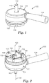
- FIG. 1 A module according to one exemplary embodiment is shown in FIG. 1 and broadly designated by the numeral 100.
- the module 100 includes a housing 102, the housing 102 having at least two sides, such as a top side 104 and a bottom side 106.
- a top side 104 a top side 104
- a bottom side 106 a bottom side 106.
- top and bottom are merely used in a relative sense and the exact location of the sides can be any suitable location, such as top, bottom, left, right, etc.
- the top side 104 is disposed generally opposite the bottom side 106.
- One or both of the top and bottom sides 104, 106 may be planar or curved.
- the top and bottom sides 104 and 106 are planar and parallel to each other.
- the housing 102 as shown has a generally cylindrical shaped wall section, but other suitable shapes are within the scope of the present disclosure.
- the housing 102 could optionally have a square or hexagonal cross-section.
- the top side 104 has an aperture 108 located in the top side 104.
- the term "aperture” refers to a passageway extending partially or entirely through a given object.
- the aperture 108 may be symmetrically disposed about the cylindrical axis of the housing 102.
- the aperture may be circular and it may be disposed at the geometric center of the top side 104.
- a rotatable spindle 110 extends outwardly through the aperture 108, protruding in a direction perpendicular to the top side 104 of the housing 102.
- the spindle 110 extends at an acute angle relative to the top side 104 or has one or more flexible joints allowing the longitudinal axis of the spindle 110 to change along its length.
- the spindle 110 has an outer end 112 adapted for releasable coupling to a power drill (not shown in this figure).
- the outer end 112 has a diameter of about 0.25 inches (6.35 millimeters) or less.
- the term "diameter" refers to the widest lateral dimension of an object, which need not be circular.
- the lateral dimension is measured along a cross-sectional plane perpendicular to the longitudinal axis of the spindle 110.
- the outer end 112 can have a round or polygonal cross-sectional shape. In some embodiments, the outer end has a hexagonal cross-section to facilitate engagement to common household power drills.
- a handle 114 is coupled to the housing 102 and extends outwardly from the housing 102 in a lateral direction.
- the handle 114 could be made integral with the housing 102.
- the handle 114 facilitates control of the module 100 by allowing an operator to grasp the handle 114 on the housing 102 with one hand while operating the power drill with the other hand. Because of the close proximity of the handle 114 to the substrate being acted upon by the module 100, gripping the handle 114 and power drill together affords the operator a significantly greater degree of control than gripping the power drill alone.
- substrate generically refers to an outer surface of a workpiece that is acted upon by the module 100.
- a dual-action assembly 116 Adjacent to and extending slightly past the bottom side 106 of the housing 102 is a dual-action assembly 116. Additional details of the assembly 116 are shown in FIGS. 2 and 3 . In these figures the module 100 is inverted, showing bottom-facing components of the assembly 116. As shown in FIG. 2 , the assembly 116 partially resides in a cavity 118 located on the bottom side 106 of the housing 102.
- the assembly 116 also has a generally cylindrical configuration. However, the diameter of the assembly 116 is smaller than that of the cavity 118, allowing the assembly 116 to rotate about a first axis 120 that represents the cylindrical axis of the assembly 116 while simultaneously orbiting about a second axis 122 that represents the cylindrical axis of the outer end 112 of the spindle 110. As shown, the axis 120 is slightly offset from the second axis 122, such that the assembly 116, as a whole, traces a circular path relative to the housing 100 during operation.
- the assembly 116 includes a generally circular backing plate 124 having a planar bottom surface and a semi-circular counterweight 126 adjacent to the backing plate 124.
- the backing plate 124 and counterweight 126 are commonly coupled to underlying components of the assembly 116 by a screw 128.
- the counterweight 126 has a size and weight that is precisely calibrated to compensate for the off-center disposition of the assembly 116 relative to the housing 102. By balancing the weight across the bottom side 106 of the housing 102, the counterweight 126 helps minimize flutter and wobbling of the module 100 during operation.
- the backing plate 124 provides six screws 130 located along its annular rim on the bottom side of the assembly 116.
- the screws 130 are preferably arranged in a standardized configuration that allows the backing plate 124 to be attached to a wide variety of work members adapted to contact the substrate, or one or more intermediary components (e.g. an interface backing plate).
- work members include abrasive discs, polishing pads, sanding pads, buffing pads, cleaning pads, and brushes.
- the second axis 122 or rotational axis of the spindle 110, forms a fixed angle with respect to the plane of the backing plate 124.
- this fixed angle is about 90 degrees, such that the shaft of the power drill is perpendicular to the substrate being abraded, polished, or cleaned. This perpendicular orientation provides the operator with enhanced control over the normal force applied to the substrate by the backing plate 124.
- each of the housing 102 and dual-action assembly 116 of the module 100 has a weight distribution that is generally symmetric about the axis 122. This also helps the operator apply even pressure across the surface of the work member.
- FIG. 4 presents the components of the module 100 in exploded view, showing the bottom-facing surfaces of each component.
- FIG. 5 is an exploded view taken from the opposite direction, showing the top-facing surfaces of each component.
- the internal components of the module 100 are preferably made from stainless steel (such as 300-series stainless steel) or polymeric composite materials. Some exterior components of the module 100, such as the housing 102, can optionally be made from aluminum.
- the screw 128 extends through a central aperture in the counterweight 126 and rigidly couples the counterweight 126 to the spindle 110.
- the spindle 110 has an inner end 132 with a "D"-shaped cross-section received in a complemental "D"-shaped recess 134 in the counterweight 126, which prevents the spindle 110 and counterweight 126 from rotating relative to each other.
- the backing plate 124 is integrally connected to spur gear 136. Although illustrated here as an integral component, the gear 136 and backing plate 124 can also be discrete components that are subsequently joined together. Captured within the backing plate 124 and the gear 136 are a pair of stacked annular bearings 138, partially visible in the bottom view of FIG. 3 . The bearings 138 occupy an annular space between the spindle 110 and the backing plate 124/gear 136 and help minimize friction as the backing plate 124/gear 136 collectively rotate about the spindle 110.
- the spindle 110 includes a pair of non-concentric cylindrical segments 144, 146 joined together end to end.
- the first segment 144 extends toward the top side of the module 100 and is generally symmetric about the second axis 122 (shown in FIG. 2 ).
- the second segment 146 extends toward the bottom side of the module 100 and is generally symmetric about the first axis 120.
- the first axis 120 orbits about the second axis 122 at a rate exactly equal to the rotation rate of the spindle 110.
- an annular gasket 140 and internal ring gear 142 are symmetrically disposed along the spindle 110.
- the gasket 140 is captured in a space between the ring gear 142 and the backing plate 124.
- These components are mutually engaged such that gear teeth extending inwardly from the ring gear 142 mesh with gear teeth extending outwardly from the spur gear 136, causing the spur gear 136 to rotate about the first axis 120 as the first axis 120 orbits about the second axis 122.
- the backing plate 124 rotates about the first axis 120 in a direction counter to its orbital direction about the second axis 122. In other words, when the backing plate 124 rotates in a clockwise direction, the first axis 120 traces a circular orbital path in a counterclockwise direction.
- the relative rates of rotation of the backing plate 124 and the spindle 110 are generally determined by the relative diameters of the ring gear 142 and spur gear 136.
- the spindle 110 and the backing plate 124 rotate at different rates according to a pre-defined ratio that is at least 5:1, at least 7:1, or at least 8:1.
- the spindle 110 and backing plate 124 rotate at different rates according to a pre-defined ratio that is at most 15:1, at most 12:1, or at most 10:1.
- the mating gears 136, 142 are helical gears to reduce noise.
- the internal ring gear 142 is then fastened to the housing 102 such that these components do not rotate relative to each other. This is accomplished here by a series of screws 148, which extend through the ring gear 142 and engage threaded apertures located on inner surfaces of the housing 102.
- annular bearings 150 are also concentrically mounted within the cavity 118 of the housing 102 adjacent the aperture 108. The bearings 150 are radially disposed between the spindle 110 and the housing 102, thereby facilitating free rotation of the spindle 110 relative to the stationary ring gear 142 and housing 102.
- the handle 114 is directly attached the outer surface of the housing 102 and extends along a direction generally parallel to the plane of the backing plate 124.
- the handle 114 allows the operator to stabilize the module 100 and prevent the housing 102 from rotating along with the spindle 110 and back plate assembly 116.
- the location of the handle 114 is also beneficial because the operator can grip the module 100 at a location close to the substrate being treated. This in turn provides a superior degree of control compared with a configuration where the operator only grips the power drill.
- the handle 114 could optionally protrude from other surfaces of the housing 102 and extend in different directions depending on the desired position for the operator's hand.
- a protective collar 152 Adjacent to the handle 114, and toward the bottom side of the module 100, a protective collar 152 encircles the housing 102 in a friction fit relation.
- the collar 152 is made from a flexible polymeric material can function as a splash guard when the module 100 is being used with liquid compositions.
- FIG. 6 is a cross-section taken along the line 6-6 indicated in FIG. 3 and shows the relative orientation of the above components in module 100 in assembled form.
- the geometric center of the backing plate 124 is slightly offset from the geometric center of the housing 102.
- the degree of offset ⁇ as defined in this figure, need not be large to provide the benefits of a dual action device. In some embodiments, the offset ranges from about 2 millimeters to about 20 millimeters.
- FIG. 7 shows an exemplary method of using the module 100 in conjunction with a suitable power drill 200, intermediary pad 202, and work member 204.
- the intermediary pad 202 is securely fastened to the backing plate 124 by the screws 130.
- the pad 202 has a planar bottom-facing surface extending across substantially all of the backing plate 124.
- the intermediary pad 202 is a compressible pad, such as an interface pad or a back-up pad.
- the intermediary pad 202 serves as a spacer or backing for the work member 204. Either or both the pad 202 and the work member 204 can be reusable.
- the work member 204 is coupled to the intermediary pad 202. Since the work member 204 directly contacts the substrate, it can be soiled or worn out quickly during use. Therefore, for the convenience of the operator, it can be advantageous for the work member 202 to be releasably coupled to the intermediary pad 202 to allow rapid replacement. It is contemplated, for example, that the intermediary pad 202 and work member 204 could have respective coupling surfaces for releasable engagement to each other. Such coupling surfaces could include for example hook and loop structures, or the mating structures described in U.S. Patent No. 6,579,161 (Chesley et al. ). Alternatively, a pressure sensitive adhesive could be used to releasably couple the intermediary pad 202 and the work member 204 to each other.
- mating coupling surfaces could additionally be used to releasably couple the backing plate 124 to the intermediary pad 202.
- the intermediary pad 202 could be omitted and coupling surfaces could be used to releasably couple the backing plate 124 directly to the work member 204.
- the backing plate 124, pad 202, and work member 204 have diameters that generally match each other.
- the module 100 could optionally be used with pads and/or work members having diameters larger than the backing plate 124. In these cases, care should be taken to ensure that adequate torque is delivered to the spindle 110 in view of the increased drag resistance resulting from the larger contact area. Further, it could be beneficial for the compressible pad 202 to be made relatively stiff such that normal force applied by the backing plate 124 is distributed evenly across the polishing pad 204.
- the outer end of the spindle 110 is then coupled to a handheld power drill 200, as shown in FIG. 7 .
- the working end of the power drill 200 has a universal chuck with adjustable grippers.
- the grippers can be expanded and contracted as needed to receive and rigidly mount the spindle 110 within the chuck.
- other powered devices besides power drills could also engage the spindle 110 to drive the module 100.
- a composition is applied either to the bottom side of the polishing pad, to the substrate, or both, after the module 100 is mounted to the drill 200.
- the composition could be, for example, lubricant, wax, liquid polishing composition, or cleaning composition.
- the operator grips a handle 206 of the drill 200 while simultaneously grasping the handle 114 of the module 100 to place the module 100 into contact with the substrate.
- the operator then depresses a trigger 208 on the drill 200 to induce rotation of the spindle 110.
- the rotation directly drives rotation of the backing plate 124 along a circular orbital path relative to the housing 102.
- the operator can laterally glide the housing 100 in a back and forth manner to abrade, polish, or clean the substrate. If desired, the operator can increase pressure on the substrate by gently urging the power drill 200 downward, while maintaining lateral control over the module using the handle 114.
- a significant and unexpected advantage of the mechanism used in the module 100 derives from its ability to directly drive both rotational and orbital motion of the backing plate 124.
- each rotation of the backing plate 124 corresponds to a certain fixed number of rotations of the spindle 110.
- the ratio between rotation rate of the backing plate 124 and the spindle 110 is constant irrespective of the drag resistance caused by friction with the substrate, good efficiency of the dual action module 100 can be achieved even with the relatively low drive speeds (or motor speeds) employed by household power drills. Since the motor speeds of the power drill are relatively easy to measure and control, the direct drive mechanism used by the module 100 also provides a high degree of predictability as to the action of the work member 204 when operating the module 100.
- the provided module 100 also provides a fixed rate of oscillation and fixed eccentric offset unlike some prior art devices. Since these characteristics are precisely defined by the rotational speed of the spindle 110 and the offset ⁇ between the first and second segments 144, 146 of the spindle 110, the module 100 can be optimized to display a particular degree of eccentricity or rotational speed for a given application. Again, this provides precise control over the dual-action motion of the work member 204.
- the drive mechanism of the module 100 nominally operates at a spindle rotation rate that does not exceed 2,500 rotations per minute. More preferably, the drive mechanism nominally operates at a spindle rotation rate that does not exceed 2,200 rotations per minute. Most preferably, the drive mechanism nominally operates at a spindle rotation rate that does not exceed 2,000 rotations per minute.
- the direct drive mechanism of the assembly 116 enables relatively lower speed motors, including those typically used in household power drills, to power a dual-action device while maintaining consistent and predictable rates of rotation and oscillation.
- the module 100 also has improved versatility compared with integrated dual-action devices because it can be used with a wide variety of commercially available power drills 200.
- the module 100 could be advantageously employed in either a corded or cordless configuration.
- the drive unit powering the module 100 is provided as a separate component, an operator has flexibility in pairing the module with a power drill 200 with a torque and/or drive speed that is best suited for the application at hand. Since many consumers already possess a power drill, the module 100 provides significant cost savings to these consumers since the inclusion of a drive motor is obviated, reducing complexity and manufacturing costs associated therewith.
- the module 100 is also relatively compact allowing it to be easily packaged, stored and transported.
- Kits and assemblies including the module 100 are also contemplated.
- the module 100 may be bundled as part of a kit containing one or more work members 204.
- the module 100 could be provided with a selected set of abrasive discs having progressively increasing grit size (or coarseness) suitable for achieving wide ranges of cut and finish.
- the set of work members 204 could include pads of different materials such as wools and various grades of open-celled foams.
- the kit could include one or more liquid compositions for use with the one or more included work members 204.
- kits can also be implemented with respect to the intermediary pads 202, which can be provided with variations in thickness, diameter, and/or stiffness.
Landscapes
- Engineering & Computer Science (AREA)
- Mechanical Engineering (AREA)
- Finish Polishing, Edge Sharpening, And Grinding By Specific Grinding Devices (AREA)
Description
- Modular devices are provided for processing a substrate. More particularly, modular devices are provided for performing orbital rotation (dual-action) processing on a substrate.
- Rotary sanders, grinders, polishers, buffers, and cleaners are used in a wide range of applications, including carpentry, metal working, vehicle detailing, and vehicle repair. These tools can also be used with diverse substrates, including marble, glass, upholstery, wood, metal and painted surfaces. The tools are sometimes adapted for specialized applications, for example when there is risk of damaging the substrate. One such application is in automotive and marine exterior detailing. Car exteriors typically include several layers of paint, which are then topped with a protective clear coat layer. Boats typically utilize a gel coat in lieu of the protective clear coat layer that may be treated in a similar fashion to automotive finishes. To obtain an aesthetically pleasing shine, car enthusiasts apply a wax or liquid polish composition to the exterior of the car and then use a rotary polisher to spread the composition and remove swirls and minor scratches from the clear coat layer.
- Simple rotary (or "single-action") polishers use a work member that rapidly spins about a fixed axis of rotation relative to the polishing device. While these devices are capable of polishing the substrate at a high cut rates, this action can also generate significant heat because the polishing head rotates at such high speeds. In the hands of an untrained operator, a single-action polisher can generate enough heat to risk "burning" the paint, which refers to the undesirable removal of paint residing below the clear coat surface. Decreasing the rotational speed of the work member can reduce this risk, but doing so can also reduce polishing efficiency below acceptable levels.
- The risks associated with a single-action polisher can be substantially mitigated while maintaining polishing efficiency by using an oscillating, dual-action polisher. Dual action polishers use a work member that spins about a central spindle, while the spindle itself rotates around an eccentric offset. Like a planet orbiting around the sun, the head of a dual-action polisher spins about a first axis while orbiting around a second axis displaced from the first axis. For this reason, these dual-action devices are also sometimes referred to as orbital polishers. The combined rotating/orbiting motion dissipates heat and can effectively prevent the polisher from burning the paint. This safety feature makes dual-action devices an attractive option for hobbyists and professionals alike.
-
GB 677 518 A - Similarly,
US 2,492,372 A andDE 91 11 520 U1 relate to a sanding or buffing devices of the type adapted to be operated by a hand drill. - Conventional dual-action devices use a freely-rotating work member (or head unit) coupled to an orbital mechanism. This mechanism is powered by a dedicated drive motor that operates at high speeds, typically in excess of 8,000-10,000 rotations per minute (rpm). These high orbital speeds are sufficient to induce self-rotation of the work member about the second axis based on the inertia of the work member as it is flung around in its orbital motion about the first axis.
- While the inertial drive mechanism can produce satisfactory results at high drive speeds (e.g. in the range of 8,000-10,000 rpm), the mechanism encounters performance limitations at lower drive speeds. At lower drive speeds, the orbital speed is also lower, which significantly reduces the driving force that rotates the work member. Since the driving force is reduced, friction between the work member and the substrate can retard or halt entirely the rotation of the work member, resulting in poor performance. The manufacturer of the device thus faces an unfortunate dilemma. While the diameter of the work member can be substantially reduced to lower the drag on the work member, this forces the operator to make additional passes to get the same job done. Use of intermediate diameters with higher orbital speeds might be feasible, but this approach increases power consumption and potentially limits the scope of applications for the device. Obviously, none of these options are ideal.
- The present invention is defined by the features of independent claim 1. Embodiments are recited in the dependent claims.
- The provided devices overcome the above problem by using a direct drive (or a forced rotation) mechanism that enables the dual-action motion to be provided by a modular component releasably coupled to an external drive motor. This approach conveniently enables the device to be used with household power drills, which typically operate at relatively low drive speeds not exceeding 2,500 rpm. These devices include a handle attached to the housing, which allows the spindle motion driven by the drive motor and the motion of the housing to be effectively decoupled from each other. The handle can be positioned close to the substrate, thus providing enhanced operator control over the dual-action head unit. By providing a modular device that can be used with a common household tool, these devices and methods provide for increased versatility as well as space and cost savings to the consumer.
-
-
FIG. 1 is a perspective view looking at the top and side surfaces of a dual-action module for a handheld power drill according to one exemplary embodiment; -
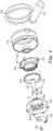
FIG. 2 is a perspective view looking at the bottom and side surfaces of the module ofFIG. 1 ; -
FIG. 3 is a plan view looking at the bottom side of the module ofFIGS. 1-2 . -
FIG. 4 is an exploded perspective view of the module ofFIGS. 1-3 , looking at the bottom and side surfaces of its components; -
FIG. 5 is an exploded perspective view of the module ofFIGS. 1-4 , looking at the top and side surfaces of its components; -
FIG. 6 is an elevational cross-sectional view of the module ofFIGS. 1-5 along the line 6-6 inFIG. 3 ; and -
FIG. 7 is a perspective view of the module ofFIGS. 1-6 coupled to the handheld power drill. - The provided dual-action modules and related kits are further described herein by way of illustration and example. In exemplary embodiments, these dual-action modules are capable of being coupled to a handheld power drill and are usable in applications including, but not limited to, sanding, compounding, cleaning, polishing, waxing and buffing automotive and marine exteriors. Analogous uses could exist in metal finishing, upholstery cleaning, and wood working.
- A module according to one exemplary embodiment is shown in
FIG. 1 and broadly designated by thenumeral 100. Themodule 100 includes ahousing 102, thehousing 102 having at least two sides, such as atop side 104 and abottom side 106. As used herein, it is to be understood that the terms "top" and "bottom" are merely used in a relative sense and the exact location of the sides can be any suitable location, such as top, bottom, left, right, etc. - In the illustrated embodiment the
top side 104 is disposed generally opposite thebottom side 106. One or both of the top andbottom sides bottom sides housing 102 as shown has a generally cylindrical shaped wall section, but other suitable shapes are within the scope of the present disclosure. For example, thehousing 102 could optionally have a square or hexagonal cross-section. - As shown, the
top side 104 has anaperture 108 located in thetop side 104. As used herein, the term "aperture" refers to a passageway extending partially or entirely through a given object. In exemplary embodiments, theaperture 108 may be symmetrically disposed about the cylindrical axis of thehousing 102. For example, the aperture may be circular and it may be disposed at the geometric center of thetop side 104. - A
rotatable spindle 110 extends outwardly through theaperture 108, protruding in a direction perpendicular to thetop side 104 of thehousing 102. In some embodiments, thespindle 110 extends at an acute angle relative to thetop side 104 or has one or more flexible joints allowing the longitudinal axis of thespindle 110 to change along its length. Thespindle 110 has anouter end 112 adapted for releasable coupling to a power drill (not shown in this figure). In some embodiments, theouter end 112 has a diameter of about 0.25 inches (6.35 millimeters) or less. As used herein, the term "diameter" refers to the widest lateral dimension of an object, which need not be circular. In this case, the lateral dimension is measured along a cross-sectional plane perpendicular to the longitudinal axis of thespindle 110. Theouter end 112 can have a round or polygonal cross-sectional shape. In some embodiments, the outer end has a hexagonal cross-section to facilitate engagement to common household power drills. - As further shown in
FIG. 1 , ahandle 114 is coupled to thehousing 102 and extends outwardly from thehousing 102 in a lateral direction. Optionally, thehandle 114 could be made integral with thehousing 102. Thehandle 114 facilitates control of themodule 100 by allowing an operator to grasp thehandle 114 on thehousing 102 with one hand while operating the power drill with the other hand. Because of the close proximity of thehandle 114 to the substrate being acted upon by themodule 100, gripping thehandle 114 and power drill together affords the operator a significantly greater degree of control than gripping the power drill alone. As used herein, the term "substrate" generically refers to an outer surface of a workpiece that is acted upon by themodule 100. - Adjacent to and extending slightly past the
bottom side 106 of thehousing 102 is a dual-action assembly 116. Additional details of theassembly 116 are shown inFIGS. 2 and3 . In these figures themodule 100 is inverted, showing bottom-facing components of theassembly 116. As shown inFIG. 2 , theassembly 116 partially resides in acavity 118 located on thebottom side 106 of thehousing 102. - Like the
housing 102, theassembly 116 also has a generally cylindrical configuration. However, the diameter of theassembly 116 is smaller than that of thecavity 118, allowing theassembly 116 to rotate about afirst axis 120 that represents the cylindrical axis of theassembly 116 while simultaneously orbiting about asecond axis 122 that represents the cylindrical axis of theouter end 112 of thespindle 110. As shown, theaxis 120 is slightly offset from thesecond axis 122, such that theassembly 116, as a whole, traces a circular path relative to thehousing 100 during operation. - Referring to
FIGS. 2 and3 , theassembly 116 includes a generallycircular backing plate 124 having a planar bottom surface and asemi-circular counterweight 126 adjacent to thebacking plate 124. Thebacking plate 124 andcounterweight 126, despite rotating at different rates relative to each other, are commonly coupled to underlying components of theassembly 116 by ascrew 128. Thecounterweight 126 has a size and weight that is precisely calibrated to compensate for the off-center disposition of theassembly 116 relative to thehousing 102. By balancing the weight across thebottom side 106 of thehousing 102, thecounterweight 126 helps minimize flutter and wobbling of themodule 100 during operation. - The
backing plate 124 provides sixscrews 130 located along its annular rim on the bottom side of theassembly 116. Thescrews 130 are preferably arranged in a standardized configuration that allows thebacking plate 124 to be attached to a wide variety of work members adapted to contact the substrate, or one or more intermediary components (e.g. an interface backing plate). The particular work member used depends on the desired application. Exemplary work members include abrasive discs, polishing pads, sanding pads, buffing pads, cleaning pads, and brushes. - One notable aspect of this configuration is that the
second axis 122, or rotational axis of thespindle 110, forms a fixed angle with respect to the plane of thebacking plate 124. Preferably and as shown, this fixed angle is about 90 degrees, such that the shaft of the power drill is perpendicular to the substrate being abraded, polished, or cleaned. This perpendicular orientation provides the operator with enhanced control over the normal force applied to the substrate by thebacking plate 124. - The configuration shown improves operator control because forces applied to press the
backing plate 124 against the substrate are aligned along the longitudinal axis of thespindle 110, thus avoiding the creation of a moment that could tip thebacking plate 124 relative to the substrate. As a further benefit over prior art devices, each of thehousing 102 and dual-action assembly 116 of themodule 100 has a weight distribution that is generally symmetric about theaxis 122. This also helps the operator apply even pressure across the surface of the work member. - As illustrated in subsequent
FIGS. 4 and5 , the dual-action motion of theassembly 116 is actuated by a direct drive mechanism whereby thebacking plate 124 and thespindle 110 are engaged to each other.FIG. 4 presents the components of themodule 100 in exploded view, showing the bottom-facing surfaces of each component.FIG. 5 is an exploded view taken from the opposite direction, showing the top-facing surfaces of each component. Unless otherwise noted, the internal components of themodule 100 are preferably made from stainless steel (such as 300-series stainless steel) or polymeric composite materials. Some exterior components of themodule 100, such as thehousing 102, can optionally be made from aluminum. - Referring now to
FIGS. 4 and5 , and starting at the bottom of themodule 100, thescrew 128 extends through a central aperture in thecounterweight 126 and rigidly couples thecounterweight 126 to thespindle 110. As shown inFIG. 5 , thespindle 110 has aninner end 132 with a "D"-shaped cross-section received in a complemental "D"-shapedrecess 134 in thecounterweight 126, which prevents thespindle 110 andcounterweight 126 from rotating relative to each other. - Optionally and as shown, the
backing plate 124 is integrally connected to spurgear 136. Although illustrated here as an integral component, thegear 136 andbacking plate 124 can also be discrete components that are subsequently joined together. Captured within thebacking plate 124 and thegear 136 are a pair of stackedannular bearings 138, partially visible in the bottom view ofFIG. 3 . Thebearings 138 occupy an annular space between thespindle 110 and thebacking plate 124/gear 136 and help minimize friction as thebacking plate 124/gear 136 collectively rotate about thespindle 110. - As seen in the figures, the
spindle 110 includes a pair of non-concentriccylindrical segments first segment 144 extends toward the top side of themodule 100 and is generally symmetric about the second axis 122 (shown inFIG. 2 ). Thesecond segment 146, on the other hand, extends toward the bottom side of themodule 100 and is generally symmetric about thefirst axis 120. As a result of this offset axis configuration, thefirst axis 120 orbits about thesecond axis 122 at a rate exactly equal to the rotation rate of thespindle 110. - Proceeding further, an
annular gasket 140 andinternal ring gear 142 are symmetrically disposed along thespindle 110. When themodule 100 is assembled, thegasket 140 is captured in a space between thering gear 142 and thebacking plate 124. These components are mutually engaged such that gear teeth extending inwardly from thering gear 142 mesh with gear teeth extending outwardly from thespur gear 136, causing thespur gear 136 to rotate about thefirst axis 120 as thefirst axis 120 orbits about thesecond axis 122. In this internal ring gear configuration, thebacking plate 124 rotates about thefirst axis 120 in a direction counter to its orbital direction about thesecond axis 122. In other words, when thebacking plate 124 rotates in a clockwise direction, thefirst axis 120 traces a circular orbital path in a counterclockwise direction. - The relative rates of rotation of the
backing plate 124 and thespindle 110 are generally determined by the relative diameters of thering gear 142 andspur gear 136. In some embodiments, thespindle 110 and thebacking plate 124 rotate at different rates according to a pre-defined ratio that is at least 5:1, at least 7:1, or at least 8:1. In some embodiments, thespindle 110 andbacking plate 124 rotate at different rates according to a pre-defined ratio that is at most 15:1, at most 12:1, or at most 10:1. In some embodiments, the mating gears 136, 142 are helical gears to reduce noise. - The
internal ring gear 142 is then fastened to thehousing 102 such that these components do not rotate relative to each other. This is accomplished here by a series ofscrews 148, which extend through thering gear 142 and engage threaded apertures located on inner surfaces of thehousing 102. Optionally and as shown,annular bearings 150 are also concentrically mounted within thecavity 118 of thehousing 102 adjacent theaperture 108. Thebearings 150 are radially disposed between thespindle 110 and thehousing 102, thereby facilitating free rotation of thespindle 110 relative to thestationary ring gear 142 andhousing 102. - As previously indicated, the
handle 114 is directly attached the outer surface of thehousing 102 and extends along a direction generally parallel to the plane of thebacking plate 124. During operation of themodule 100, thehandle 114 allows the operator to stabilize themodule 100 and prevent thehousing 102 from rotating along with thespindle 110 and backplate assembly 116. The location of thehandle 114 is also beneficial because the operator can grip themodule 100 at a location close to the substrate being treated. This in turn provides a superior degree of control compared with a configuration where the operator only grips the power drill. Although not shown here, thehandle 114 could optionally protrude from other surfaces of thehousing 102 and extend in different directions depending on the desired position for the operator's hand. - Adjacent to the
handle 114, and toward the bottom side of themodule 100, aprotective collar 152 encircles thehousing 102 in a friction fit relation. In some embodiments, thecollar 152 is made from a flexible polymeric material can function as a splash guard when themodule 100 is being used with liquid compositions. -
FIG. 6 is a cross-section taken along the line 6-6 indicated inFIG. 3 and shows the relative orientation of the above components inmodule 100 in assembled form. As illustrated, the geometric center of thebacking plate 124 is slightly offset from the geometric center of thehousing 102. The degree of offset δ, as defined in this figure, need not be large to provide the benefits of a dual action device. In some embodiments, the offset ranges from about 2 millimeters to about 20 millimeters. -
FIG. 7 shows an exemplary method of using themodule 100 in conjunction with asuitable power drill 200,intermediary pad 202, andwork member 204. First, theintermediary pad 202 is securely fastened to thebacking plate 124 by thescrews 130. Preferably and as shown, thepad 202 has a planar bottom-facing surface extending across substantially all of thebacking plate 124. In some embodiments theintermediary pad 202 is a compressible pad, such as an interface pad or a back-up pad. In some embodiments, theintermediary pad 202 serves as a spacer or backing for thework member 204. Either or both thepad 202 and thework member 204 can be reusable. - Second, the
work member 204 is coupled to theintermediary pad 202. Since thework member 204 directly contacts the substrate, it can be soiled or worn out quickly during use. Therefore, for the convenience of the operator, it can be advantageous for thework member 202 to be releasably coupled to theintermediary pad 202 to allow rapid replacement. It is contemplated, for example, that theintermediary pad 202 andwork member 204 could have respective coupling surfaces for releasable engagement to each other. Such coupling surfaces could include for example hook and loop structures, or the mating structures described inU.S. Patent No. 6,579,161 (Chesley et al. ). Alternatively, a pressure sensitive adhesive could be used to releasably couple theintermediary pad 202 and thework member 204 to each other. - Other combinations are also possible. For example, mating coupling surfaces could additionally be used to releasably couple the
backing plate 124 to theintermediary pad 202. Alternatively, theintermediary pad 202 could be omitted and coupling surfaces could be used to releasably couple thebacking plate 124 directly to thework member 204. - Optionally and as shown in
FIG. 7 , thebacking plate 124,pad 202, andwork member 204 have diameters that generally match each other. However, if desired, themodule 100 could optionally be used with pads and/or work members having diameters larger than thebacking plate 124. In these cases, care should be taken to ensure that adequate torque is delivered to thespindle 110 in view of the increased drag resistance resulting from the larger contact area. Further, it could be beneficial for thecompressible pad 202 to be made relatively stiff such that normal force applied by thebacking plate 124 is distributed evenly across thepolishing pad 204. - Third, the outer end of the
spindle 110 is then coupled to ahandheld power drill 200, as shown inFIG. 7 . In a common embodiment, the working end of thepower drill 200 has a universal chuck with adjustable grippers. The grippers can be expanded and contracted as needed to receive and rigidly mount thespindle 110 within the chuck. Although not shown here, other powered devices besides power drills could also engage thespindle 110 to drive themodule 100. - For some applications, a composition is applied either to the bottom side of the polishing pad, to the substrate, or both, after the
module 100 is mounted to thedrill 200. The composition could be, for example, lubricant, wax, liquid polishing composition, or cleaning composition. - Finally, to operate the
module 100, the operator grips ahandle 206 of thedrill 200 while simultaneously grasping thehandle 114 of themodule 100 to place themodule 100 into contact with the substrate. The operator then depresses a trigger 208 on thedrill 200 to induce rotation of thespindle 110. As thespindle 110 is rotated relative to thehousing 102, the rotation directly drives rotation of thebacking plate 124 along a circular orbital path relative to thehousing 102. From here, the operator can laterally glide thehousing 100 in a back and forth manner to abrade, polish, or clean the substrate. If desired, the operator can increase pressure on the substrate by gently urging thepower drill 200 downward, while maintaining lateral control over the module using thehandle 114. - A significant and unexpected advantage of the mechanism used in the
module 100 derives from its ability to directly drive both rotational and orbital motion of thebacking plate 124. As a result, each rotation of thebacking plate 124 corresponds to a certain fixed number of rotations of thespindle 110. Because the ratio between rotation rate of thebacking plate 124 and thespindle 110 is constant irrespective of the drag resistance caused by friction with the substrate, good efficiency of thedual action module 100 can be achieved even with the relatively low drive speeds (or motor speeds) employed by household power drills. Since the motor speeds of the power drill are relatively easy to measure and control, the direct drive mechanism used by themodule 100 also provides a high degree of predictability as to the action of thework member 204 when operating themodule 100. - Assuming a given drive speed, the provided
module 100 also provides a fixed rate of oscillation and fixed eccentric offset unlike some prior art devices. Since these characteristics are precisely defined by the rotational speed of thespindle 110 and the offset δ between the first andsecond segments spindle 110, themodule 100 can be optimized to display a particular degree of eccentricity or rotational speed for a given application. Again, this provides precise control over the dual-action motion of thework member 204. - In preferred embodiments, the drive mechanism of the
module 100 nominally operates at a spindle rotation rate that does not exceed 2,500 rotations per minute. More preferably, the drive mechanism nominally operates at a spindle rotation rate that does not exceed 2,200 rotations per minute. Most preferably, the drive mechanism nominally operates at a spindle rotation rate that does not exceed 2,000 rotations per minute. Again, the direct drive mechanism of theassembly 116 enables relatively lower speed motors, including those typically used in household power drills, to power a dual-action device while maintaining consistent and predictable rates of rotation and oscillation. - The
module 100 also has improved versatility compared with integrated dual-action devices because it can be used with a wide variety of commercially available power drills 200. For example, themodule 100 could be advantageously employed in either a corded or cordless configuration. Because the drive unit powering themodule 100 is provided as a separate component, an operator has flexibility in pairing the module with apower drill 200 with a torque and/or drive speed that is best suited for the application at hand. Since many consumers already possess a power drill, themodule 100 provides significant cost savings to these consumers since the inclusion of a drive motor is obviated, reducing complexity and manufacturing costs associated therewith. Themodule 100 is also relatively compact allowing it to be easily packaged, stored and transported. - Kits and assemblies including the
module 100 are also contemplated. For example, themodule 100 may be bundled as part of a kit containing one ormore work members 204. For example, in abrasive applications, themodule 100 could be provided with a selected set of abrasive discs having progressively increasing grit size (or coarseness) suitable for achieving wide ranges of cut and finish. In automotive care, the set ofwork members 204 could include pads of different materials such as wools and various grades of open-celled foams. As another variant, the kit could include one or more liquid compositions for use with the one or more includedwork members 204. Similarly, kits can also be implemented with respect to theintermediary pads 202, which can be provided with variations in thickness, diameter, and/or stiffness. - The embodiments described above are illustrative of the present invention and other constructions are also possible. Accordingly, the present invention should not be deemed limited to the embodiments described in detail above and shown in the accompanying drawings.
Claims (5)
- A module (100) adapted for use with a handheld power drill (200) comprising:a housing (102) having first and second sides (104, 106);a rotatable spindle (110) extending outwardly from the first side (104), the spindle (110) having an outer end (112) adapted for releasable coupling to the power drill (200);a direct drive mechanism coupled to the spindle (110); anda handle (114) coupled to the housing (102) to facilitate control over the module (100) by an operator; anda backing plate (124) located adjacent the second side (106) and engaged to the direct drive mechanism whereby rotation of the spindle (110) directly drives rotation of the backing plate (124), the rotation occurring along a circular orbital path relative to the housing (102); wherein the module lacks any structure that couples the housing to the power drill and prevents rotation of the housing during operation,
wherein the spindle (110) and backing plate (124) rotate at different rates according to a pre-defined ratio ranging from 5:1 to 15:1 and wherein
the relative rates of rotation of the backing plate (124) and the spindle (110) are generally determined by the relative diameters of a ring gear (142) and spur gear (136). - The module (100) of claim 1 or 2, further comprising a work member (204) engaged to the backing plate (124), the work member (204) selected from the group consisting of: an abrasive disc, brush, polishing pad, buffing pad, and cleaning pad.
- The module (100) of claim 2, further comprising an intermediary pad (202) disposed between the work member (204) and the backing plate (124).
- The module (100) of claim 3, wherein the intermediary pad (202) comprises a compressible pad.
- A dual-action device kit comprising the module (100) of claim 1 and one or more work members (204) adapted for releasable engagement to the backing plate (124).
Applications Claiming Priority (2)
| Application Number | Priority Date | Filing Date | Title |
|---|---|---|---|
| US201161511736P | 2011-07-26 | 2011-07-26 | |
| PCT/US2012/047352 WO2013016123A1 (en) | 2011-07-26 | 2012-07-19 | Modular dual-action devices and related methods |
Publications (2)
| Publication Number | Publication Date |
|---|---|
| EP2736675A1 EP2736675A1 (en) | 2014-06-04 |
| EP2736675B1 true EP2736675B1 (en) | 2020-09-23 |
Family
ID=46584396
Family Applications (1)
| Application Number | Title | Priority Date | Filing Date |
|---|---|---|---|
| EP12740832.6A Active EP2736675B1 (en) | 2011-07-26 | 2012-07-19 | Modular dual-action device |
Country Status (3)
| Country | Link |
|---|---|
| US (1) | US9511472B2 (en) |
| EP (1) | EP2736675B1 (en) |
| WO (1) | WO2013016123A1 (en) |
Families Citing this family (7)
| Publication number | Priority date | Publication date | Assignee | Title |
|---|---|---|---|---|
| US9833878B2 (en) * | 2014-07-03 | 2017-12-05 | Cuong Van Nguyen | Method and apparatus for deburring a surface |
| US10603760B2 (en) * | 2017-09-19 | 2020-03-31 | Campbell Hausfeld, Llc | Multifunction rotary tool including hub |
| US10414014B2 (en) * | 2017-09-19 | 2019-09-17 | Campbell Hausfeld, Llc | Multifunction rotary tool including driveshaft |
| CN107941589B (en) * | 2017-12-04 | 2020-05-05 | 太原理工大学 | Flexible grinding device of cylinder rock test piece |
| EP3693132B1 (en) * | 2019-02-08 | 2023-09-06 | Guido Valentini | Hand-held and hand-guided random orbital polishing or sanding power tool |
| CN110732424B (en) * | 2019-10-31 | 2020-06-30 | 诸暨正道科技有限公司 | A convenient waxing device |
| CN113084679B (en) * | 2021-05-10 | 2022-05-06 | 佛山旭达建材科技有限公司 | A kind of construction aluminum formwork recycling and reprocessing method |
Citations (2)
| Publication number | Priority date | Publication date | Assignee | Title |
|---|---|---|---|---|
| FR918379A (en) * | 1945-12-04 | 1947-02-06 | Improvements to devices for the treatment of all surfaces | |
| US2553688A (en) * | 1947-06-13 | 1951-05-22 | Howard O Thompson | Tool attachment |
Family Cites Families (18)
| Publication number | Priority date | Publication date | Assignee | Title |
|---|---|---|---|---|
| US2492372A (en) * | 1948-05-04 | 1949-12-27 | Smith Wayne | Sanding or buffing device |
| GB677518A (en) * | 1949-02-22 | 1952-08-20 | Fast Inc Du | Improvements in or relating to mounting devices for rubbing machines |
| US2722789A (en) * | 1953-02-12 | 1955-11-08 | Fast Inc Du | Rubbing attachment for portable rotary power units |
| JPS5627773A (en) * | 1979-08-09 | 1981-03-18 | Uriyuu Seisaku Kk | Oscillator device of orbital sanding machine |
| GB8407058D0 (en) * | 1984-03-19 | 1984-04-26 | Black & Decker Inc | Attachments for power tools |
| DE3935179A1 (en) * | 1989-10-23 | 1991-04-25 | Werkzeug Gmbh | ATTACHMENT FOR AN ANGLE GRINDER |
| DE9111520U1 (en) * | 1991-09-17 | 1993-01-28 | Werkzeug GmbH, 5441 Weibern | Eccentric grinding head |
| US5349786A (en) * | 1993-09-27 | 1994-09-27 | Dorrah James M | Apparatus and method for producing and oscillating, an orbiting and a vibrating movement on a disc body |
| TW317223U (en) | 1994-01-13 | 1997-10-01 | Minnesota Mining & Mfg | Abrasive article |
| US5464367A (en) * | 1994-06-03 | 1995-11-07 | Zink, Jr.; Richard W. | Sanding tool for connection with a rotating drive |
| US5980371A (en) * | 1997-03-17 | 1999-11-09 | The Desmond-Stephan Mfg. Co. | Abrading tool |
| US6009767A (en) * | 1998-04-23 | 2000-01-04 | Rudolph; Gary | Same-RPM rotary motion to eccentric rotary motion conversion |
| US20020077038A1 (en) * | 2000-10-11 | 2002-06-20 | Stegner Roy L. | Method and apparatus for repairing the surface of a compact disc |
| DE10134308A1 (en) | 2001-07-14 | 2003-01-30 | Bosch Gmbh Robert | Hand tool |
| US20050272360A1 (en) * | 2004-06-08 | 2005-12-08 | Mariusz Tyranowski | Sander attachment for a drill |
| US7399140B2 (en) * | 2006-07-27 | 2008-07-15 | Lauro Barcenas | Power trowel attachment for a drill |
| US7892073B1 (en) * | 2009-01-12 | 2011-02-22 | Gary L. Smania | Bowling ball abrader and polisher system and method |
| US8845397B1 (en) * | 2011-07-25 | 2014-09-30 | AR Tips and Tools, Inc. | Surface abrasion tool |
-
2012
- 2012-07-19 US US14/232,932 patent/US9511472B2/en active Active
- 2012-07-19 EP EP12740832.6A patent/EP2736675B1/en active Active
- 2012-07-19 WO PCT/US2012/047352 patent/WO2013016123A1/en not_active Ceased
Patent Citations (2)
| Publication number | Priority date | Publication date | Assignee | Title |
|---|---|---|---|---|
| FR918379A (en) * | 1945-12-04 | 1947-02-06 | Improvements to devices for the treatment of all surfaces | |
| US2553688A (en) * | 1947-06-13 | 1951-05-22 | Howard O Thompson | Tool attachment |
Also Published As
| Publication number | Publication date |
|---|---|
| US20140187127A1 (en) | 2014-07-03 |
| US9511472B2 (en) | 2016-12-06 |
| WO2013016123A1 (en) | 2013-01-31 |
| EP2736675A1 (en) | 2014-06-04 |
Similar Documents
| Publication | Publication Date | Title |
|---|---|---|
| US9511472B2 (en) | Modular dual-action devices and related methods | |
| US9731412B2 (en) | Hand operated power tool | |
| CN111546199B (en) | Hand-held and hand-guided random orbital burnishing or sanding power tool | |
| JP3205051U (en) | Polishing unit, deburring device, polishing device, deburring robot, polishing robot | |
| US20090183887A1 (en) | Power hand tool system with universal flexible shaft and method of operating | |
| US20170312877A1 (en) | Hand held or hand guided grinding or polishing machine tool | |
| EP3421179A1 (en) | Polishing pad for releasable attachment to a bottom surface of a plate-like backing pad of a power tool, backing pad and hand-held power tool | |
| US2633008A (en) | Resilient coupling | |
| US8251782B2 (en) | Accumulator driven angle grinder | |
| CN105500188A (en) | Multi-head fit type polishing machine | |
| JP6249808B2 (en) | Self-leveling sanding machine | |
| WO2012083749A1 (en) | Dual-wheel abrader and dual-wheel polisher | |
| CN212044060U (en) | Polishing equipment for industrial machinery | |
| CN214519995U (en) | Hand-held and/or hand-operated power tools | |
| AU2005338255A1 (en) | Sand pad lock for sander | |
| JP2012206211A (en) | Dust collection adapter and power tool including dust collection adapter | |
| CN114888684A (en) | Grinding device for machining | |
| JP3157305U (en) | Portable disc grinder | |
| US5464367A (en) | Sanding tool for connection with a rotating drive | |
| US20100075581A1 (en) | Extended utility tool | |
| CN218531912U (en) | Full-automatic vehicle polishing, waxing and cleaning device | |
| US20120115404A1 (en) | Handheld, Portable Drum Sander | |
| JP2006263900A (en) | Handheld grinder for polishing/grinding | |
| KR20050097369A (en) | Grinder having a dust collecting structure | |
| GB2420090A (en) | An electrically powered grinding tool |
Legal Events
| Date | Code | Title | Description |
|---|---|---|---|
| PUAI | Public reference made under article 153(3) epc to a published international application that has entered the european phase |
Free format text: ORIGINAL CODE: 0009012 |
|
| 17P | Request for examination filed |
Effective date: 20140128 |
|
| AK | Designated contracting states |
Kind code of ref document: A1 Designated state(s): AL AT BE BG CH CY CZ DE DK EE ES FI FR GB GR HR HU IE IS IT LI LT LU LV MC MK MT NL NO PL PT RO RS SE SI SK SM TR |
|
| DAX | Request for extension of the european patent (deleted) | ||
| STAA | Information on the status of an ep patent application or granted ep patent |
Free format text: STATUS: EXAMINATION IS IN PROGRESS |
|
| 17Q | First examination report despatched |
Effective date: 20180710 |
|
| GRAP | Despatch of communication of intention to grant a patent |
Free format text: ORIGINAL CODE: EPIDOSNIGR1 |
|
| STAA | Information on the status of an ep patent application or granted ep patent |
Free format text: STATUS: GRANT OF PATENT IS INTENDED |
|
| INTG | Intention to grant announced |
Effective date: 20200513 |
|
| GRAS | Grant fee paid |
Free format text: ORIGINAL CODE: EPIDOSNIGR3 |
|
| GRAA | (expected) grant |
Free format text: ORIGINAL CODE: 0009210 |
|
| STAA | Information on the status of an ep patent application or granted ep patent |
Free format text: STATUS: THE PATENT HAS BEEN GRANTED |
|
| AK | Designated contracting states |
Kind code of ref document: B1 Designated state(s): AL AT BE BG CH CY CZ DE DK EE ES FI FR GB GR HR HU IE IS IT LI LT LU LV MC MK MT NL NO PL PT RO RS SE SI SK SM TR |
|
| REG | Reference to a national code |
Ref country code: GB Ref legal event code: FG4D |
|
| REG | Reference to a national code |
Ref country code: CH Ref legal event code: EP |
|
| REG | Reference to a national code |
Ref country code: DE Ref legal event code: R096 Ref document number: 602012072450 Country of ref document: DE |
|
| REG | Reference to a national code |
Ref country code: IE Ref legal event code: FG4D |
|
| REG | Reference to a national code |
Ref country code: AT Ref legal event code: REF Ref document number: 1315904 Country of ref document: AT Kind code of ref document: T Effective date: 20201015 |
|
| PG25 | Lapsed in a contracting state [announced via postgrant information from national office to epo] |
Ref country code: HR Free format text: LAPSE BECAUSE OF FAILURE TO SUBMIT A TRANSLATION OF THE DESCRIPTION OR TO PAY THE FEE WITHIN THE PRESCRIBED TIME-LIMIT Effective date: 20200923 Ref country code: SE Free format text: LAPSE BECAUSE OF FAILURE TO SUBMIT A TRANSLATION OF THE DESCRIPTION OR TO PAY THE FEE WITHIN THE PRESCRIBED TIME-LIMIT Effective date: 20200923 Ref country code: BG Free format text: LAPSE BECAUSE OF FAILURE TO SUBMIT A TRANSLATION OF THE DESCRIPTION OR TO PAY THE FEE WITHIN THE PRESCRIBED TIME-LIMIT Effective date: 20201223 Ref country code: GR Free format text: LAPSE BECAUSE OF FAILURE TO SUBMIT A TRANSLATION OF THE DESCRIPTION OR TO PAY THE FEE WITHIN THE PRESCRIBED TIME-LIMIT Effective date: 20201224 Ref country code: NO Free format text: LAPSE BECAUSE OF FAILURE TO SUBMIT A TRANSLATION OF THE DESCRIPTION OR TO PAY THE FEE WITHIN THE PRESCRIBED TIME-LIMIT Effective date: 20201223 Ref country code: FI Free format text: LAPSE BECAUSE OF FAILURE TO SUBMIT A TRANSLATION OF THE DESCRIPTION OR TO PAY THE FEE WITHIN THE PRESCRIBED TIME-LIMIT Effective date: 20200923 |
|
| REG | Reference to a national code |
Ref country code: AT Ref legal event code: MK05 Ref document number: 1315904 Country of ref document: AT Kind code of ref document: T Effective date: 20200923 |
|
| PG25 | Lapsed in a contracting state [announced via postgrant information from national office to epo] |
Ref country code: LV Free format text: LAPSE BECAUSE OF FAILURE TO SUBMIT A TRANSLATION OF THE DESCRIPTION OR TO PAY THE FEE WITHIN THE PRESCRIBED TIME-LIMIT Effective date: 20200923 Ref country code: RS Free format text: LAPSE BECAUSE OF FAILURE TO SUBMIT A TRANSLATION OF THE DESCRIPTION OR TO PAY THE FEE WITHIN THE PRESCRIBED TIME-LIMIT Effective date: 20200923 |
|
| REG | Reference to a national code |
Ref country code: NL Ref legal event code: MP Effective date: 20200923 |
|
| REG | Reference to a national code |
Ref country code: LT Ref legal event code: MG4D |
|
| PG25 | Lapsed in a contracting state [announced via postgrant information from national office to epo] |
Ref country code: SM Free format text: LAPSE BECAUSE OF FAILURE TO SUBMIT A TRANSLATION OF THE DESCRIPTION OR TO PAY THE FEE WITHIN THE PRESCRIBED TIME-LIMIT Effective date: 20200923 Ref country code: RO Free format text: LAPSE BECAUSE OF FAILURE TO SUBMIT A TRANSLATION OF THE DESCRIPTION OR TO PAY THE FEE WITHIN THE PRESCRIBED TIME-LIMIT Effective date: 20200923 Ref country code: NL Free format text: LAPSE BECAUSE OF FAILURE TO SUBMIT A TRANSLATION OF THE DESCRIPTION OR TO PAY THE FEE WITHIN THE PRESCRIBED TIME-LIMIT Effective date: 20200923 Ref country code: LT Free format text: LAPSE BECAUSE OF FAILURE TO SUBMIT A TRANSLATION OF THE DESCRIPTION OR TO PAY THE FEE WITHIN THE PRESCRIBED TIME-LIMIT Effective date: 20200923 Ref country code: PT Free format text: LAPSE BECAUSE OF FAILURE TO SUBMIT A TRANSLATION OF THE DESCRIPTION OR TO PAY THE FEE WITHIN THE PRESCRIBED TIME-LIMIT Effective date: 20210125 Ref country code: CZ Free format text: LAPSE BECAUSE OF FAILURE TO SUBMIT A TRANSLATION OF THE DESCRIPTION OR TO PAY THE FEE WITHIN THE PRESCRIBED TIME-LIMIT Effective date: 20200923 Ref country code: EE Free format text: LAPSE BECAUSE OF FAILURE TO SUBMIT A TRANSLATION OF THE DESCRIPTION OR TO PAY THE FEE WITHIN THE PRESCRIBED TIME-LIMIT Effective date: 20200923 |
|
| PG25 | Lapsed in a contracting state [announced via postgrant information from national office to epo] |
Ref country code: AT Free format text: LAPSE BECAUSE OF FAILURE TO SUBMIT A TRANSLATION OF THE DESCRIPTION OR TO PAY THE FEE WITHIN THE PRESCRIBED TIME-LIMIT Effective date: 20200923 Ref country code: AL Free format text: LAPSE BECAUSE OF FAILURE TO SUBMIT A TRANSLATION OF THE DESCRIPTION OR TO PAY THE FEE WITHIN THE PRESCRIBED TIME-LIMIT Effective date: 20200923 Ref country code: ES Free format text: LAPSE BECAUSE OF FAILURE TO SUBMIT A TRANSLATION OF THE DESCRIPTION OR TO PAY THE FEE WITHIN THE PRESCRIBED TIME-LIMIT Effective date: 20200923 Ref country code: PL Free format text: LAPSE BECAUSE OF FAILURE TO SUBMIT A TRANSLATION OF THE DESCRIPTION OR TO PAY THE FEE WITHIN THE PRESCRIBED TIME-LIMIT Effective date: 20200923 Ref country code: IS Free format text: LAPSE BECAUSE OF FAILURE TO SUBMIT A TRANSLATION OF THE DESCRIPTION OR TO PAY THE FEE WITHIN THE PRESCRIBED TIME-LIMIT Effective date: 20210123 |
|
| REG | Reference to a national code |
Ref country code: DE Ref legal event code: R097 Ref document number: 602012072450 Country of ref document: DE |
|
| PG25 | Lapsed in a contracting state [announced via postgrant information from national office to epo] |
Ref country code: SK Free format text: LAPSE BECAUSE OF FAILURE TO SUBMIT A TRANSLATION OF THE DESCRIPTION OR TO PAY THE FEE WITHIN THE PRESCRIBED TIME-LIMIT Effective date: 20200923 |
|
| PLBE | No opposition filed within time limit |
Free format text: ORIGINAL CODE: 0009261 |
|
| STAA | Information on the status of an ep patent application or granted ep patent |
Free format text: STATUS: NO OPPOSITION FILED WITHIN TIME LIMIT |
|
| PG25 | Lapsed in a contracting state [announced via postgrant information from national office to epo] |
Ref country code: SI Free format text: LAPSE BECAUSE OF FAILURE TO SUBMIT A TRANSLATION OF THE DESCRIPTION OR TO PAY THE FEE WITHIN THE PRESCRIBED TIME-LIMIT Effective date: 20200923 Ref country code: DK Free format text: LAPSE BECAUSE OF FAILURE TO SUBMIT A TRANSLATION OF THE DESCRIPTION OR TO PAY THE FEE WITHIN THE PRESCRIBED TIME-LIMIT Effective date: 20200923 |
|
| 26N | No opposition filed |
Effective date: 20210624 |
|
| PG25 | Lapsed in a contracting state [announced via postgrant information from national office to epo] |
Ref country code: IT Free format text: LAPSE BECAUSE OF FAILURE TO SUBMIT A TRANSLATION OF THE DESCRIPTION OR TO PAY THE FEE WITHIN THE PRESCRIBED TIME-LIMIT Effective date: 20200923 |
|
| REG | Reference to a national code |
Ref country code: CH Ref legal event code: PL |
|
| PG25 | Lapsed in a contracting state [announced via postgrant information from national office to epo] |
Ref country code: MC Free format text: LAPSE BECAUSE OF FAILURE TO SUBMIT A TRANSLATION OF THE DESCRIPTION OR TO PAY THE FEE WITHIN THE PRESCRIBED TIME-LIMIT Effective date: 20200923 |
|
| REG | Reference to a national code |
Ref country code: BE Ref legal event code: MM Effective date: 20210731 |
|
| PG25 | Lapsed in a contracting state [announced via postgrant information from national office to epo] |
Ref country code: LI Free format text: LAPSE BECAUSE OF NON-PAYMENT OF DUE FEES Effective date: 20210731 Ref country code: CH Free format text: LAPSE BECAUSE OF NON-PAYMENT OF DUE FEES Effective date: 20210731 |
|
| PG25 | Lapsed in a contracting state [announced via postgrant information from national office to epo] |
Ref country code: LU Free format text: LAPSE BECAUSE OF NON-PAYMENT OF DUE FEES Effective date: 20210719 Ref country code: FR Free format text: LAPSE BECAUSE OF NON-PAYMENT OF DUE FEES Effective date: 20210731 |
|
| PG25 | Lapsed in a contracting state [announced via postgrant information from national office to epo] |
Ref country code: IE Free format text: LAPSE BECAUSE OF NON-PAYMENT OF DUE FEES Effective date: 20210719 Ref country code: BE Free format text: LAPSE BECAUSE OF NON-PAYMENT OF DUE FEES Effective date: 20210731 |
|
| PG25 | Lapsed in a contracting state [announced via postgrant information from national office to epo] |
Ref country code: HU Free format text: LAPSE BECAUSE OF FAILURE TO SUBMIT A TRANSLATION OF THE DESCRIPTION OR TO PAY THE FEE WITHIN THE PRESCRIBED TIME-LIMIT; INVALID AB INITIO Effective date: 20120719 Ref country code: CY Free format text: LAPSE BECAUSE OF FAILURE TO SUBMIT A TRANSLATION OF THE DESCRIPTION OR TO PAY THE FEE WITHIN THE PRESCRIBED TIME-LIMIT Effective date: 20200923 |
|
| PG25 | Lapsed in a contracting state [announced via postgrant information from national office to epo] |
Ref country code: MK Free format text: LAPSE BECAUSE OF FAILURE TO SUBMIT A TRANSLATION OF THE DESCRIPTION OR TO PAY THE FEE WITHIN THE PRESCRIBED TIME-LIMIT Effective date: 20200923 |
|
| PG25 | Lapsed in a contracting state [announced via postgrant information from national office to epo] |
Ref country code: MT Free format text: LAPSE BECAUSE OF FAILURE TO SUBMIT A TRANSLATION OF THE DESCRIPTION OR TO PAY THE FEE WITHIN THE PRESCRIBED TIME-LIMIT Effective date: 20200923 |
|
| PGFP | Annual fee paid to national office [announced via postgrant information from national office to epo] |
Ref country code: GB Payment date: 20250619 Year of fee payment: 14 |
|
| PGFP | Annual fee paid to national office [announced via postgrant information from national office to epo] |
Ref country code: DE Payment date: 20250620 Year of fee payment: 14 |
|
| PG25 | Lapsed in a contracting state [announced via postgrant information from national office to epo] |
Ref country code: TR Free format text: LAPSE BECAUSE OF FAILURE TO SUBMIT A TRANSLATION OF THE DESCRIPTION OR TO PAY THE FEE WITHIN THE PRESCRIBED TIME-LIMIT Effective date: 20200923 |