EP2736164B1 - Method for efficiency optimization of a wind generator by controlling the electrical generator and system therefor - Google Patents
Method for efficiency optimization of a wind generator by controlling the electrical generator and system therefor Download PDFInfo
- Publication number
- EP2736164B1 EP2736164B1 EP13386032.0A EP13386032A EP2736164B1 EP 2736164 B1 EP2736164 B1 EP 2736164B1 EP 13386032 A EP13386032 A EP 13386032A EP 2736164 B1 EP2736164 B1 EP 2736164B1
- Authority
- EP
- European Patent Office
- Prior art keywords
- generator
- opt
- wind
- speed
- optimal
- Prior art date
- Legal status (The legal status is an assumption and is not a legal conclusion. Google has not performed a legal analysis and makes no representation as to the accuracy of the status listed.)
- Active
Links
- 238000000034 method Methods 0.000 title claims description 43
- 238000005457 optimization Methods 0.000 title claims description 9
- 230000006698 induction Effects 0.000 claims description 39
- 241000555745 Sciuridae Species 0.000 claims description 29
- XEEYBQQBJWHFJM-UHFFFAOYSA-N iron Substances [Fe] XEEYBQQBJWHFJM-UHFFFAOYSA-N 0.000 claims description 20
- 230000001360 synchronised effect Effects 0.000 claims description 8
- 238000003306 harvesting Methods 0.000 claims description 7
- 101100243401 Caenorhabditis elegans pept-3 gene Proteins 0.000 claims description 6
- 230000001276 controlling effect Effects 0.000 claims description 5
- 230000004907 flux Effects 0.000 claims description 5
- 229910052742 iron Inorganic materials 0.000 claims description 4
- 230000001105 regulatory effect Effects 0.000 claims description 4
- 101100189913 Caenorhabditis elegans pept-1 gene Proteins 0.000 claims description 3
- 238000006243 chemical reaction Methods 0.000 description 16
- 238000005259 measurement Methods 0.000 description 8
- 230000004044 response Effects 0.000 description 8
- 238000009434 installation Methods 0.000 description 5
- 238000011160 research Methods 0.000 description 5
- 238000004519 manufacturing process Methods 0.000 description 4
- 238000010586 diagram Methods 0.000 description 3
- 230000009467 reduction Effects 0.000 description 3
- 238000013528 artificial neural network Methods 0.000 description 2
- 238000011217 control strategy Methods 0.000 description 2
- 238000007796 conventional method Methods 0.000 description 2
- 239000013256 coordination polymer Substances 0.000 description 2
- 230000006872 improvement Effects 0.000 description 2
- 230000003044 adaptive effect Effects 0.000 description 1
- 238000002474 experimental method Methods 0.000 description 1
- 238000000605 extraction Methods 0.000 description 1
- 238000009533 lab test Methods 0.000 description 1
- 230000001537 neural effect Effects 0.000 description 1
- 230000003287 optical effect Effects 0.000 description 1
- 238000010248 power generation Methods 0.000 description 1
- 238000012549 training Methods 0.000 description 1
Images


Classifications
-
- H—ELECTRICITY
- H02—GENERATION; CONVERSION OR DISTRIBUTION OF ELECTRIC POWER
- H02P—CONTROL OR REGULATION OF ELECTRIC MOTORS, ELECTRIC GENERATORS OR DYNAMO-ELECTRIC CONVERTERS; CONTROLLING TRANSFORMERS, REACTORS OR CHOKE COILS
- H02P9/00—Arrangements for controlling electric generators for the purpose of obtaining a desired output
-
- F—MECHANICAL ENGINEERING; LIGHTING; HEATING; WEAPONS; BLASTING
- F03—MACHINES OR ENGINES FOR LIQUIDS; WIND, SPRING, OR WEIGHT MOTORS; PRODUCING MECHANICAL POWER OR A REACTIVE PROPULSIVE THRUST, NOT OTHERWISE PROVIDED FOR
- F03D—WIND MOTORS
- F03D7/00—Controlling wind motors
- F03D7/02—Controlling wind motors the wind motors having rotation axis substantially parallel to the air flow entering the rotor
- F03D7/0272—Controlling wind motors the wind motors having rotation axis substantially parallel to the air flow entering the rotor by measures acting on the electrical generator
-
- H—ELECTRICITY
- H02—GENERATION; CONVERSION OR DISTRIBUTION OF ELECTRIC POWER
- H02P—CONTROL OR REGULATION OF ELECTRIC MOTORS, ELECTRIC GENERATORS OR DYNAMO-ELECTRIC CONVERTERS; CONTROLLING TRANSFORMERS, REACTORS OR CHOKE COILS
- H02P21/00—Arrangements or methods for the control of electric machines by vector control, e.g. by control of field orientation
-
- Y—GENERAL TAGGING OF NEW TECHNOLOGICAL DEVELOPMENTS; GENERAL TAGGING OF CROSS-SECTIONAL TECHNOLOGIES SPANNING OVER SEVERAL SECTIONS OF THE IPC; TECHNICAL SUBJECTS COVERED BY FORMER USPC CROSS-REFERENCE ART COLLECTIONS [XRACs] AND DIGESTS
- Y02—TECHNOLOGIES OR APPLICATIONS FOR MITIGATION OR ADAPTATION AGAINST CLIMATE CHANGE
- Y02E—REDUCTION OF GREENHOUSE GAS [GHG] EMISSIONS, RELATED TO ENERGY GENERATION, TRANSMISSION OR DISTRIBUTION
- Y02E10/00—Energy generation through renewable energy sources
- Y02E10/70—Wind energy
- Y02E10/72—Wind turbines with rotation axis in wind direction
Definitions
- This invention relates to wind generators that use induction generators (squirrel cage asynchronous generators).
- This invention discloses a method for efficiency optimization of a wind energy conversion system by controlling the electric generator. This is implemented by means of a control scheme based on the control of the generator rotor speed and achieves simultaneously maximization of the efficiencies of wind turbine and electrical generator and therefore efficiency maximization of the total wind energy conversion system.
- Main advantages of the control scheme are the simple implementation, easy installation and satisfactory quick response so as it can follow the fast changes of wind speed.
- the wind generator converts the kinetic energy of the wind into electrical energy that is provided either to an isolated electric consumer (stand-alone wind generator) or to the grid (grid connected wind generator).
- the presented invention can be applied in both cases of wind generators.
- the wind generators that are mainly used in wind energy conversion systems are squirrel cage induction generators, slip ring induction generators and permanent magnet synchronous generators.
- the presented invention is applicable to wind generators with squirrel cage induction generators and especially relates to low and medium power wind generators.
- the wind turbine provides electric energy when the wind speed is greater than a threshold, known as cut-in wind speed. If the wind speed is less than this threshold, the produced energy is not sufficient even to cover the electric and mechanical losses in the wind energy conversion system. Thus, in order to be produced maximum electric energy, the power loss should be minimized at each part of the wind system. This can be achieved by the appropriate control of the generator electric variables. Also, the proper control of the wind turbine rotor speed in relation to the respective wind speed may result in maximization of the output power. The above two goals can provide maximum efficiency of the total wind system. However, it is important that the control of the system should be simple, accurate to its result and fast in order to detect the changes of the wind speed. Also, it should not be affected the manufacturing cost and can be easily applicable to any wind generation system.
- Kioskeridis 'Maximum efficiency of a wind energy conversion system with a PM synchronous generator', in Proc. MedPower 2010 Int. Conf., pp. 1-9 and A. Mesemanolis and C. Mademlis, 'A Neural Network Based MPPT Controller for Variable Speed Wind Energy Conversion Systems', Speedam Conf. June 2012 .
- control scheme Due to the above, the cut-in wind speed is reduced and therefore optimal utilization of the wind system is accomplished, since more electric energy can be produced form the existing wind energy potential.
- the main feature of the control scheme is that only the measurement of the generator rotation speed is needed which is the input to the control scheme, while the measurement of the wind speed is not required.
- the advantages of the control scheme is the fast response because the optimal values of the field and torque currents are determined through appropriate mathematical equations that serve as control conditions in the closed-loop system.
- the control scheme has the capability to track the quick changes of the wind speed. It has also simple implementation and easy installation because it is not based on look-up tables that may require time consuming laboratory experiments.
- the presented control scheme is a comprehensive, simple and cost-effective solution to the problem of efficiency optimization in a wind energy conversion system with squirrel cage induction generator.
- a control scheme for the rectifier converter of a wind generator with squirrel cage induction generator that implements the efficiency optimization control method above, comprising two controllers that operate simultaneously, have common input the generator speed and they determine the optimal values of the reference field and torque stator currents of the electric generator.
- the reference field component of the stator current I ds ⁇ determines the optimal magnetic flux so as loss minimization of the squirrel cage induction generator is accomplished.
- the reference torque component of the stator current I qs ⁇ determines the optimal rotational speed of the squirrel cage induction generator so as maximum power harvesting of the wind turbine is accomplished.
- the parameters G d , T a and T b are determined by the eqns. (10) below and depend on the stator and rotor resistances ( R s and R r respectively), the magnetizing and rotor inductances ( L m and L r , respectively), the iron loss coefficient C Fe and the stray loss coefficient c str of the squirrel cage induction generator.
- the parameters G q 1 and G q 2 are determined experimentally through curve fitting of the eqn. (20) below and also the parameter G q of said eqn. (20) is determined by the eqn. (17) below and depends on the pole pairs p and the magnetizing and rotor inductances ( L m and L r , respectively) of the squirrel cage induction generator, the air density p, the gear ratio n, the mechanical loss coefficient c m of the wind system, the radius of the blades R , the optimal value of tip speed ratio ⁇ opt and the optimal value of the aerodynamic coefficient C Popt of the wind turbine.
- the rectifier converter of the wind generator with squirrel cage induction generator is implemented by a fully controlled IGBT converter that utilizes field oriented control through space-vector modulation.
- the reference field component of the stator current I ds ⁇ is regulated through a controller that implements the condition of eqn. (21) below and the input to the controller is the rotational speed ⁇ r of the squirrel cage induction generator.
- the reference torque component of the stator current I qs ⁇ is regulated through a controller that implements the condition of eqn. (22) below and the input to the controller is the rotational speed ⁇ r of the squirrel cage induction generator.
- a method for efficiency optimization of a wind generator by controlling the squirrel cage induction generator is proposed.
- the method achieves simultaneously maximum efficiency of the wind turbine (wind mill) and maximum efficiency of the electric generator through the minimization of its electric loss. Additionally, expansion of the exploitable wind speed region is accomplished through the reduction of the cut-in speed at which the wind system starts to provide power to the grid.
- the method is implemented by appropriately controlling the power rectifier and without requiring the measurement of the wind speed.
- Input to the control scheme is the rotational speed of the electric generator.
- the control scheme comprises two controllers that, for any wind speed, provide the optimal reference field and torque stator current components of the squirrel cage induction generator. The two current components are determined through optimal conditions.
- the main advantages of the presented control scheme are the quick response so as it can follow the fast changes of the wind speed and also the simple implementation and the easy installation.
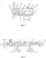
- Figure 1 shows the various parts of a typical wind generator. It consists of a wind turbine 1, a gear-box 2, an electric generator 3, a shaft 4, a brake 5, an anemometer 6 and a support frame 7.
- a wind turbine 1 it is included the blades, the hub and the nose cone.
- the shaft 4 connects the wind turbine with the gear box; whereas in case of direct driven wind turbines, the shaft connects the wind turbine with the electric generator.
- a blades pitch control system is usually installed. All the above components are installed in the nacelle 8.
- 9 is the yaw control system that adjusts the nacelle to the wind direction and 10 is the tower.
- FIG. 2 shows a control scheme of the wind generation system, through which, the invention is implemented. It consists of two back-to-back converters.
- the power converter at the generator side 1 operates as a rectifier and controls the induction generator.
- the power converter 2 operates as an inverter and converts the dc power provided by the rectifier to ac power, which after passing through an L-C-L filter 3 it is injected to the grid 4.
- the rectifier control scheme 5 and the inverter control scheme 6 operate at this invention by the vector control technique.
- the rectifier control scheme regulates the two components of the generator stator current i.e. field current I ds and torque current I qs , in order to obtain maximum power from the wind generator.
- the inverter control scheme regulates the I dN and I qN components of the output current to the grid, in order to maintain constant the dc-link voltage and to control the reactive power to the grid, respectively.
- the speed ⁇ e is the electric synchronous speed of the generator which is needed in the condition of the loss minimization controller 1 and is determined through the closed-loop control system 3. Specifically, the rotor flux-linkage ⁇ r is determined through the I ds ⁇ and then, the slip angular velocity ⁇ sl is determined by using the ⁇ r and the reference q-axis stator current I qs ⁇ . The optimal values of the electric generator stator current components I ds ⁇ and I qs ⁇ are determined through the respective optimal conditions. The above control procedure is followed for all the cases that the reference currents I ds ⁇ and I qs ⁇ are lower than their respective rated values.
- the currents I ds ⁇ and I qs ⁇ cannot exceed their maximum values, because they are limited by the Limiters 5 and 6, respectively. This could be occurred either during transients or at high wind speeds.
- the electric variables of the squirrel cage induction generator are controlled by using only the mechanical speed of the rotor shaft. Consequently, the efficiency of the wind generator can be optimized by measuring only the rotor speed.
- the optimal reference values of the two stator current components are determined quickly and with satisfactory accuracy, since they are online calculated through the respective two mathematical conditions. This results in quick response of the system and thus it can follow the fast changes of the wind speed.
- the presented control scheme provides maximum efficiency of the wind energy conversion system (i.e. maximum efficiency of the wind turbine and maximum efficiency of the electric generator) and consists of two controllers that are implemented by eqs. (21) and (22), respectively.
- Input to the control scheme is the rotor speed and outputs are the references of field and torque current components of the generator stator current.
- the knowledge of the coefficients G d , G q 1 , G q 2 , T a ⁇ T b in conditions (21) and (22) is required.
- the values of the above coefficients can be determined experimentally through an off-line experimental procedure and therefore the knowledge of the exact models of the generator and wind turbine is not required.
- Figure 4 shows the implementation diagram of the invention in a 5 kW wind system.
- the wind energy is converted to kinetic energy at the shaft of the turbine 1 and through the electric generator 2 it is converted to electric power.
- the shaft speed is measured by an optical encoder 3 that is installed at the generator shaft.
- the shaft speed is needed for the implementation of the vector control in the rectifier control scheme and also for the implementation of the electric generator stator current control in order to achieve maximum efficiency in the wind system.
- the power that is produced by the generator passes through the power converter system 4 and then it is injected to the grid 5.
- the power converter system 4 is supervised by two control schemes, the rectifier control scheme 6 and the inverter control scheme 7.
- the signal of the shaft rotational speed of the squirrel cage induction generator is driven to the rectifier control scheme 6 that is implemented in a microcontroller.
- the rectifier control scheme consists of two controllers: the loss minimization controller of the electric generator 8 and the maximum power tracking controller of the wind turbine 9. Common input for both controllers is the signal of the rotational speed ⁇ r and outputs are the reference signals of the field and torque stator currents I ds ⁇ and I qs ⁇ , respectively.
- the two controllers operate simultaneously and implement the two optimal conditions of eqs. (21) and (22).
- the two controllers provide the optimal reference currents I ds ⁇ and I qs ⁇ that are determined by the two control conditions and thereby, maximum efficiency operation of the wind system can be reached in only a few cycles of the digital controller.
- the above control procedure continues for all cases that the reference currents I ds ⁇ and I qs ⁇ are less than their respective nominal values.
- the output signals I ds ⁇ and I qs ⁇ of the two controllers do not exceed their nominal values because they are constrained by the Limiters (10) and (11). This may occur during transients and in high wind speeds.
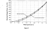
- Figure 5 compares the variation of the electric output power to the grid versus wind speed of a 5 kW wind system with the presented control technique (optimal method) against the conventional operation of the system at which only maximum power point tracking control is applied, MPPT control (conventional method). In both cases, a gear box with speed ratio 4 is used. From this diagram it is concluded that, from the same wind energy potential, the electric power production is increased by the presented optimal control scheme for all wind speed cases and also, the system starts to produce electric power from lower wind speed values (reduction of the cut-in wind speed). Specifically, the wind system with the optimal control starts to provide power to the grid from wind speed of 3.6 m/s, whereas the conventional system starts to provide power to the grid from 4.26 m/s. The above is achieved because with the proposed optimal control, maximum power from the wind turbine is accomplished and also increased percentage of the wind turbine energy is converted to electrical energy to grid, since the electric loss in the generator is minimized.
- Figures 6a and 6b show the performance of the 5 kW wind energy conversion system with the optimal control, for a time period of 2.5 min. From these figures it is resulted that the wind system exhibits quick response and satisfactory dynamic performance at the changes of the wind speed. This can be concluded from the fact that, the aerodynamic power coefficient C P has almost constant value of 0.43 that corresponds to the maximum efficiency of the wind turbine, at all wind speed cases. Also, it is validated that the optimal control scheme provides electric power to the grid at lower wind speed than 4.26 m/s, at which the conventional system starts to provide power to the grid.
Description
- This invention relates to wind generators that use induction generators (squirrel cage asynchronous generators). This invention discloses a method for efficiency optimization of a wind energy conversion system by controlling the electric generator. This is implemented by means of a control scheme based on the control of the generator rotor speed and achieves simultaneously maximization of the efficiencies of wind turbine and electrical generator and therefore efficiency maximization of the total wind energy conversion system. Main advantages of the control scheme are the simple implementation, easy installation and satisfactory quick response so as it can follow the fast changes of wind speed.
- The wind generator converts the kinetic energy of the wind into electrical energy that is provided either to an isolated electric consumer (stand-alone wind generator) or to the grid (grid connected wind generator). The presented invention can be applied in both cases of wind generators.
- The wind generators that are mainly used in wind energy conversion systems are squirrel cage induction generators, slip ring induction generators and permanent magnet synchronous generators. The presented invention is applicable to wind generators with squirrel cage induction generators and especially relates to low and medium power wind generators.
- The wind turbine provides electric energy when the wind speed is greater than a threshold, known as cut-in wind speed. If the wind speed is less than this threshold, the produced energy is not sufficient even to cover the electric and mechanical losses in the wind energy conversion system. Thus, in order to be produced maximum electric energy, the power loss should be minimized at each part of the wind system. This can be achieved by the appropriate control of the generator electric variables. Also, the proper control of the wind turbine rotor speed in relation to the respective wind speed may result in maximization of the output power. The above two goals can provide maximum efficiency of the total wind system. However, it is important that the control of the system should be simple, accurate to its result and fast in order to detect the changes of the wind speed. Also, it should not be affected the manufacturing cost and can be easily applicable to any wind generation system.
- A variety of techniques have been proposed in the past for the optimal control of the wind generator speed in order to harvest maximum power from the incident wind. In Us
4,525,633 of 25 June 1985 , the optimal rotational speed of the turbine is determined from the wind speed. This technique requires the measurement of the wind speed that is difficult to be accurately obtained since the anemometer is usually positioned in the rear part of the nacelle that results in inaccurate measurement. - In
US 4,695,736 of 22 September 1978 , the optimal speed of the wind turbine is determined through a look-up table; however, numerous experimental measurements are required for determining the necessary look-up table of reference speed vs. sensed power. InUS 5,155,375 of 13 October 1992 , the wind speed is estimated in time steps through an observer and then the optimal rotational speed of the wind turbine is determined; however, the proposed technique can approximately follow the varying wind speeds. - In
US 7,304,400 B2 of 4 December 2007 , a sensorless control technique for wind generation systems is proposed, where the shaft speed is estimated by the electric variables of the generator and inUS 7,095,131 B2 of 22 August 2006 , a control technique is presented, that is applicable to wind systems with slip ring induction generators, at which the turbine speed is controlled through the q-axis component of the rotor current. - Several research efforts have been also carried out so far to address the problem of improving the efficiency of the wind energy conversion system. Specifically, several methods have been proposed for maximizing the efficiency of wind turbines that either employ fuzzy-logic control techniques (R.M. Hilloowala and A.M. Sharaf, 'A rule-based fuzzy logic controller for a PWM inverter in a stand-alone wind energy conversion scheme', IEEE Trans. Ind. Appl., vol. 32, no. 1, pp. 57-65, Jan./Feb. 1996) and are based on the search control technique (R. Datta and V. T. Ranganathan, 'A method of tracking the peak power points for a variable speed wind energy conversion system', IEEE Trans. Energy Convers., vol. 18, no. 1, pp. 163-168, March 2003). However, a common feature of the above methods is that they have slow response and consequently they cannot follow the fast changes of the wind speed. The methods that are based on the neural network technique (such as the work of M. Pucci and M. Cirrincione, 'Neural MPPT control of generators with induction machines with-out speed sensors', IEEE Trans. Ind. Electron., vol. 58, no. 1, pp. 37-47, Jan. 2011) require a long time training for the system and consequently they cannot be directly applicable.
- Several improved techniques to the above methods have been presented in the technical literature (Munteanu, S. Bacha, A. I. Bratcu, J. Guiraud, and D. Roye, 'Energy-reliability optimization of wind energy conversion systems by sliding mode control', IEEE Trans. Energy Convers., vol. 23, no. 3, pp. 975-984, Sept. 2008 and V. Galdi, A. Piccolo, and P. Siano, 'Designing an adaptive fuzzy controller for maximum wind energy extraction', IEEE Trans. Energy Convers., vol. 23, no. 2, pp. 559-569, June 2008); however, they are complicated and also the knowledge of the power curves of the wind turbine is required for their implementation.
- In relation to the above, several techniques have been proposed for the improvement of the electrical generator efficiency through electric variables control. In
US 5,075,612 of 24 December 1991 , a control method for the magnetic field in a dc machine is presented in order to accomplish loss minimization. InUS 7,312,592 of 25 December 2007 , a control method for efficiency maximization of electric motors through specific current profiles is presented and inUS 6,711,556 of 23 March 2004 , by using the fuzzy-logic control method. - In
US 7,854,283 B3 of 21 December 2010 , a method that optimizes the efficiency of a power system is presented that can be applied to wind systems and takes into account various operating variables, i.e. wind conditions, ambient temperature, load level, etc. In the control technique that is presented inUS 8,098,054 B2 of 17 January 2012 , it is attempted to optimize the efficiency of a power system from the load side. Finally, inUS 7,798,631 of 25 August 1998 , a fuzzy-logic control method is proposed for improving the efficiency of the electric generator of a wind system. - In addition to the above and with emphasis on electric generators efficiency improvement of wind systems, the research efforts are focused on the control of the d-axis component of the electric generator stator current (field current). In the work of A. G. Abo-Khalil, H. G. Kim, D. C. Lee, and J. K. Seok, 'Maximum output power control of wind generation system considering loss minimization machines', in Proc. IEEE Int. Conf. IECON 2004, pp. 1676-1681, a condition for the optimal field current for induction generator is proposed. However, this condition is not accurate because it disregards the variation of the iron loss with respect to stator current frequency. In research work of A. G. Abo-Khalil, 'Model-based optimal efficiency control of induction generator for wind power systems', in Proc. Conf. Rec. ICIT-2011, pp. 191-197, a similar condition for the field current is proposed; however, it depends on the wind speed for which is well known that there are several difficulties for obtaining an accurate measurement. The research work of A. Mesemanolis, C. Mademlis, and I. Kioskeridis, 'A fuzzy-logic based control strategy for maximum efficiency of a wind energy conversion system', in Proc. IEEE Intern, Symposium on Power Electronics SPEEDAM 2012, pp. 7-12, also deals with wind energy conversion system efficiency maximization; however, since it is based on the fuzzy-logic control technique, it is very slow and cannot follow the fast changes of the wind speed. Also, a control strategy based on search control technique for both maximum power harvesting from the wind turbine and minimum power loss of the induction generator has been proposed in the paper of A. Mesemanolis, C. Mademlis, and I, Kioskeridis, 'Maximum electrical energy production of a variable speed wind energy conversion system', in Proc. IEEE Int. Symposium ISIE 2012, pp. 1029-1034; however, the response of the wind energy system is very slow and cannot follow the fast changes of the wind speed.
- Research works concerning the efficiency optimization of wind turbines with permanent magnet synchronous generator are presented in the following papers: M. Chinchilla, S. Arnaltes, and J. C. Burgos, 'Control of permanent-magnet generators applied to variable-speed wind-energy systems connected to the grid', IEEE Trans. Energy Convers., vol. 21, no. 1, pp. 130-135, March 2006, W. Qiao, L. Qu, and R. G. Harley, 'Control of IPM synchronous generator for maximum wind power generation considering magnetic saturation', IEEE Trans. Ind. Appl., vol. 45, no. 3, pp. 1095-1105, May/June 2009, A. Mesemanolis, C. Mademlis, and I. Kioskeridis, 'Maximum efficiency of a wind energy conversion system with a PM synchronous generator', in Proc. MedPower 2010 Int. Conf., pp. 1-9 and A. Mesemanolis and C. Mademlis, 'A Neural Network Based MPPT Controller for Variable Speed Wind Energy Conversion Systems', Speedam Conf. June 2012.
- The presented invention is defined in
claims - Due to the above, the cut-in wind speed is reduced and therefore optimal utilization of the wind system is accomplished, since more electric energy can be produced form the existing wind energy potential. The main feature of the control scheme is that only the measurement of the generator rotation speed is needed which is the input to the control scheme, while the measurement of the wind speed is not required. The advantages of the control scheme is the fast response because the optimal values of the field and torque currents are determined through appropriate mathematical equations that serve as control conditions in the closed-loop system. Thus, the control scheme has the capability to track the quick changes of the wind speed. It has also simple implementation and easy installation because it is not based on look-up tables that may require time consuming laboratory experiments. Moreover, it does not only burden the manufacturing cost, but needs less hardware than a standard system setup because it does not require anemometer for wind speed measurement. Therefore, the presented control scheme is a comprehensive, simple and cost-effective solution to the problem of efficiency optimization in a wind energy conversion system with squirrel cage induction generator.
- In this respect there is proposed according to a particular embodiment of the invention, a control scheme for the rectifier converter of a wind generator with squirrel cage induction generator that implements the efficiency optimization control method above, comprising two controllers that operate simultaneously, have common input the generator speed and they determine the optimal values of the reference field and torque stator currents of the electric generator.
- According to a further embodiment of the method of the invention, the reference field component of the stator current

- According to a still further embodiment of the method of the invention, the reference torque component of the stator current

- According to a yet further embodiment of the method of the invention, the parameters Gd, Ta and Tb are determined by the eqns. (10) below and depend on the stator and rotor resistances (Rs and Rr respectively), the magnetizing and rotor inductances (Lm and Lr , respectively), the iron loss coefficient CFe and the stray loss coefficient cstr of the squirrel cage induction generator.
- According to an even further embodiment of the method of the invention, the parameters G q1 and G q2 are determined experimentally through curve fitting of the eqn. (20) below and also the parameter Gq of said eqn. (20) is determined by the eqn. (17) below and depends on the pole pairs p and the magnetizing and rotor inductances (Lm and Lr , respectively) of the squirrel cage induction generator, the air density p, the gear ratio n, the mechanical loss coefficient cm of the wind system, the radius of the blades R, the optimal value of tip speed ratio λopt and the optimal value of the aerodynamic coefficient CPopt of the wind turbine.
- According to another embodiment of the invention, the rectifier converter of the wind generator with squirrel cage induction generator is implemented by a fully controlled IGBT converter that utilizes field oriented control through space-vector modulation.
- According to another particular embodiment of the invention, the reference field component of the stator current

- According to an additional embodiment of the invention, the reference torque component of the stator current

- To summarise, it is thus proposed according to the invention a method for efficiency optimization of a wind generator by controlling the squirrel cage induction generator is proposed. The method achieves simultaneously maximum efficiency of the wind turbine (wind mill) and maximum efficiency of the electric generator through the minimization of its electric loss. Additionally, expansion of the exploitable wind speed region is accomplished through the reduction of the cut-in speed at which the wind system starts to provide power to the grid. The method is implemented by appropriately controlling the power rectifier and without requiring the measurement of the wind speed. Input to the control scheme is the rotational speed of the electric generator. The control scheme comprises two controllers that, for any wind speed, provide the optimal reference field and torque stator current components of the squirrel cage induction generator. The two current components are determined through optimal conditions. The main advantages of the presented control scheme are the quick response so as it can follow the fast changes of the wind speed and also the simple implementation and the easy installation.
-
Figure 1 shows the various parts of a typical wind generator. It consists of awind turbine 1, a gear-box 2, anelectric generator 3, ashaft 4, abrake 5, ananemometer 6 and asupport frame 7. In thewind turbine 1, it is included the blades, the hub and the nose cone. Theshaft 4 connects the wind turbine with the gear box; whereas in case of direct driven wind turbines, the shaft connects the wind turbine with the electric generator. In medium and high power wind generation systems, a blades pitch control system is usually installed. All the above components are installed in thenacelle 8. Finally, 9 is the yaw control system that adjusts the nacelle to the wind direction and 10 is the tower. -
Figure 2 shows a control scheme of the wind generation system, through which, the invention is implemented. It consists of two back-to-back converters. The power converter at thegenerator side 1 operates as a rectifier and controls the induction generator. Thepower converter 2 operates as an inverter and converts the dc power provided by the rectifier to ac power, which after passing through anL-C-L filter 3 it is injected to thegrid 4. Therectifier control scheme 5 and theinverter control scheme 6 operate at this invention by the vector control technique. Thus, the rectifier control scheme regulates the two components of the generator stator current i.e. field current Ids and torque current Iqs , in order to obtain maximum power from the wind generator. The inverter control scheme regulates the IdN and IqN components of the output current to the grid, in order to maintain constant the dc-link voltage and to control the reactive power to the grid, respectively. -
Figure 3 shows the block diagram of the rectifier control scheme, where ωsl is the slip angular velocity and TR is the rotor time constant (TR = Lr / Rr ). All the other variables are defined at the mathematical determination of the optimal conditions. It is composed of theloss minimization controller 1 which determines the reference optimal field current


loss minimization controller 1 and is determined through the closed-loop control system 3. Specifically, the rotor flux-linkage ψr is determined through the


Limiters - The analytical solution for the optimal field and torque current conditions is following:
- a) The loss minimization of the squirrel cage induction generator can be achieved through the appropriate control of the magnetic field by controlling the field current component of the stator current. If Ids and Iqs are the two components of the stator current and Idr and Iqr are the two components of the rotor current, the electric loss of the squirrel cage induction generator is given by

At steady state, the rotor flux linkage ψr is aligned to the d-axis, (ψdr = ψr and ψqr = 0) and therefore


- b) Maximum power harvesting of the wind turbine is achieved with proper adjustment of the rotational speed through the stator torque current component of the electric generator. The power captured by the wind turbine is given by


- c) The two conditions that are given in eqs. (9) and (16) should hold simultaneously in order to be concurrently achieved loss minimization in the generator and maximum power harvesting from the wind turbine. Therefore, from eqs. (9) and (16), it is concluded that the optimal conditions for the reference field and torque stator current components of squirrel cage induction generator are given by the following equations


- Since the gain Gq varies with electric generator saturation and specifically it increases as saturation increases, because of Lm reduction, the Gq should be an increasing function of the load and hence an increasing function of the wind turbine speed

- The influence of saturation on the parameter Ta is negligible because the magnetizing inductance Lm is in the nominator and denominator of the fraction and therefore, its influence is neutralized. Also, by taking into account that the parameter Tb reduces as saturation increases, the influence of saturation on


- The influence of temperature variation on the optimal conditions of


- The presented control scheme provides maximum efficiency of the wind energy conversion system (i.e. maximum efficiency of the wind turbine and maximum efficiency of the electric generator) and consists of two controllers that are implemented by eqs. (21) and (22), respectively. Input to the control scheme is the rotor speed and outputs are the references of field and torque current components of the generator stator current. For the implementation of the above two controllers, the knowledge of the coefficients Gd, G q1, G q2, Ta καTb in conditions (21) and (22) is required. The values of the above coefficients can be determined experimentally through an off-line experimental procedure and therefore the knowledge of the exact models of the generator and wind turbine is not required.

- The advantages of the presented control scheme are summarized as follows:
- a) the knowledge of the wind speed is not required and therefore less hardware is needed (anemometer is not mounted) compared to a conventional installation,
- b) the knowledge of the model parameters of the wind turbine and electric generator is not required except those that are already needed for the vector control of the rectifier, in contrast to other conventional methods that need look-up tables of the above parameters, and therefore the proposed control scheme provides easy implementation and simple installation, and finally,
- c) the control scheme has quick response because the optimal efficiency operating point of wind system is not searched and therefore it can follow the quick changes of the wind speed.
-
Figure 4 shows the implementation diagram of the invention in a 5 kW wind system. The wind energy is converted to kinetic energy at the shaft of theturbine 1 and through theelectric generator 2 it is converted to electric power. The shaft speed is measured by anoptical encoder 3 that is installed at the generator shaft. The shaft speed is needed for the implementation of the vector control in the rectifier control scheme and also for the implementation of the electric generator stator current control in order to achieve maximum efficiency in the wind system. The power that is produced by the generator passes through thepower converter system 4 and then it is injected to thegrid 5. Thepower converter system 4 is supervised by two control schemes, therectifier control scheme 6 and theinverter control scheme 7. - According to the present invention, the signal of the shaft rotational speed of the squirrel cage induction generator is driven to the
rectifier control scheme 6 that is implemented in a microcontroller. The rectifier control scheme consists of two controllers: the loss minimization controller of theelectric generator 8 and the maximum power tracking controller of thewind turbine 9. Common input for both controllers is the signal of the rotational speed ωr and outputs are the reference signals of the field and torque stator currents


-
Figure 5 compares the variation of the electric output power to the grid versus wind speed of a 5 kW wind system with the presented control technique (optimal method) against the conventional operation of the system at which only maximum power point tracking control is applied, MPPT control (conventional method). In both cases, a gear box withspeed ratio 4 is used. From this diagram it is concluded that, from the same wind energy potential, the electric power production is increased by the presented optimal control scheme for all wind speed cases and also, the system starts to produce electric power from lower wind speed values (reduction of the cut-in wind speed). Specifically, the wind system with the optimal control starts to provide power to the grid from wind speed of 3.6 m/s, whereas the conventional system starts to provide power to the grid from 4.26 m/s. The above is achieved because with the proposed optimal control, maximum power from the wind turbine is accomplished and also increased percentage of the wind turbine energy is converted to electrical energy to grid, since the electric loss in the generator is minimized. -
Figures 6a and 6b show the performance of the 5 kW wind energy conversion system with the optimal control, for a time period of 2.5 min. From these figures it is resulted that the wind system exhibits quick response and satisfactory dynamic performance at the changes of the wind speed. This can be concluded from the fact that, the aerodynamic power coefficient CP has almost constant value of 0.43 that corresponds to the maximum efficiency of the wind turbine, at all wind speed cases. Also, it is validated that the optimal control scheme provides electric power to the grid at lower wind speed than 4.26 m/s, at which the conventional system starts to provide power to the grid.
Claims (8)
- A method for efficiency optimization of a wind generator by controlling the squirrel cage induction generator that can simultaneously achieve maximum power harvesting from the wind turbine and maximum efficiency of the electric generator by means of minimizing its electric loss, characterized by the following steps:a) the generator speed ωr is measured by a sensor at the generator rotor shaft and it is the only input signal,b) the reference field current

 c) the reference torque current
 d) the above parameters Gd as defined in the equation


opt , and π is equal to 3,14, whereby the parameters Gq1 and Gq2 are determined experimentally through curve fitting, and wherein λopt is given by
 e) the synchronous angular velocity ωe is needed as feedback signal for the previous steps b) and c) and is calculated by the vector control close-loop of the electrical generator by considering the magnetizing inductance Lm and the rotor time constant TR = Lr / Rr , where Rr is the rotor ohmic resistance and Lr is the rotor inductance Lr =Lm +Llr where Llr is the rotor flux-leakage, and finally,f) the reference currents

- Method according to the claim 1, characterised in that the reference field component of the stator current

- Method according to one of the claims 1 or 2, characterised in that the reference torque component of the stator current

- Method according to one of the claims 1 to 3, characterised in that the parameters G q1 and G q2 are determined experimentally through curve fitting of the equation Gq = G q1 + G q2 ωr wherein the parameter Gq is determined by the equation

- System with a control scheme for the rectifier converter of a wind generator with squirrel cage induction generator characterised in that it implements the efficiency optimization control method of the claim 1, and that it comprises two controllers (5,6) that operate simultaneously by having common input the generator speed ωr and they determine the optimal values of the reference field and torque stator currents of the electric generator for determining the optimal


- System according to claim 5, characterised in that the rectifier converter of the wind generator with squirrel cage induction generator is implemented by a fully controlled IGBT converter that utilizes field oriented control through space-vector modulation.
- System according to one of the claims 5 or 6, characterised in that the reference field component of the stator current


- System according to one of the claims 5 to 7, characterised in that the reference torque component of the stator current


Applications Claiming Priority (1)
| Application Number | Priority Date | Filing Date | Title |
|---|---|---|---|
| GR20120100602A GR1008117B (en) | 2012-11-27 | 2012-11-27 | Method for efficiency optimization of a wind generator by controlling the electrical generator |
Publications (3)
| Publication Number | Publication Date |
|---|---|
| EP2736164A2 EP2736164A2 (en) | 2014-05-28 |
| EP2736164A3 EP2736164A3 (en) | 2015-12-09 |
| EP2736164B1 true EP2736164B1 (en) | 2020-08-19 |
Family
ID=49911378
Family Applications (1)
| Application Number | Title | Priority Date | Filing Date |
|---|---|---|---|
| EP13386032.0A Active EP2736164B1 (en) | 2012-11-27 | 2013-11-27 | Method for efficiency optimization of a wind generator by controlling the electrical generator and system therefor |
Country Status (2)
| Country | Link |
|---|---|
| EP (1) | EP2736164B1 (en) |
| GR (1) | GR1008117B (en) |
Families Citing this family (7)
| Publication number | Priority date | Publication date | Assignee | Title |
|---|---|---|---|---|
| GB2551701A (en) * | 2016-06-21 | 2018-01-03 | Univ Court Univ Of Edinburgh | Control or processing system and method |
| CN106357178B (en) * | 2016-09-30 | 2018-09-18 | 中车株洲电力机车研究所有限公司 | A kind of low-speed direct driving Wind turbines electric drive system efficiency-optimized control method |
| CN107273647B (en) * | 2017-08-07 | 2020-08-11 | 曲阜师范大学 | Low-speed gear box doubly-fed wind turbine generator optimization design method based on direct-current power transmission |
| CN110176781B (en) * | 2019-05-24 | 2023-04-28 | 上海电力学院 | Frequency division power transmission wind power generation system and method based on isolation type variable frequency transformer |
| CN111900909B (en) * | 2020-06-17 | 2021-09-07 | 成都飞机工业(集团)有限责任公司 | Control method of airplane starting and generating integrated motor |
| CN111987955B (en) * | 2020-09-01 | 2022-06-10 | 长沙贝士德电气科技有限公司 | Self-adaptive sliding mode control system and method for salient pole type permanent magnet synchronous motor |
| CN112523945B (en) * | 2020-12-29 | 2021-11-30 | 重庆邮电大学 | Active disturbance rejection nonlinear control method for maximum wind energy capture of double-fed wind turbine |
Family Cites Families (11)
| Publication number | Priority date | Publication date | Assignee | Title |
|---|---|---|---|---|
| US4525633A (en) | 1982-09-28 | 1985-06-25 | Grumman Aerospace Corporation | Wind turbine maximum power tracking device |
| US4695736A (en) | 1985-11-18 | 1987-09-22 | United Technologies Corporation | Variable speed wind turbine |
| GR1000285B (en) | 1990-01-03 | 1992-05-12 | Nikolaos Margaris | Method and arrangement for determinating the excitation optimal value |
| US5155375A (en) | 1991-09-19 | 1992-10-13 | U.S. Windpower, Inc. | Speed control system for a variable speed wind turbine |
| US6600240B2 (en) | 1997-08-08 | 2003-07-29 | General Electric Company | Variable speed wind turbine generator |
| US7011498B2 (en) | 1998-04-03 | 2006-03-14 | Athena Technologies, Inc. | Optimization method for power generation systems |
| US6711556B1 (en) | 1999-09-30 | 2004-03-23 | Ford Global Technologies, Llc | Fuzzy logic controller optimization |
| JP4168252B2 (en) | 2002-12-27 | 2008-10-22 | 株式会社安川電機 | Power generation system and control method thereof |
| US7312592B2 (en) | 2004-04-26 | 2007-12-25 | Maslov Boris A | Adaptive system for optimizing excitation current waveform profiles for electric motors |
| US7798631B2 (en) | 2007-07-23 | 2010-09-21 | Xerox Corporation | System and method for lubricating a transfer roller with an image member |
| US8098054B2 (en) | 2007-10-10 | 2012-01-17 | John Alexander Verschuur | Optimal load controller method and device |
-
2012
- 2012-11-27 GR GR20120100602A patent/GR1008117B/en active IP Right Grant
-
2013
- 2013-11-27 EP EP13386032.0A patent/EP2736164B1/en active Active
Non-Patent Citations (1)
| Title |
|---|
| A. G. ABO-KHALIL; H. G. KIM; D. C. LEE; J. K. SEOK: "Maximum output power control of wind generation system considering loss minimization machines", PROC. IEEE INT. CONF. IECON, 2004, pages 1676 - 1681 * |
Also Published As
| Publication number | Publication date |
|---|---|
| EP2736164A3 (en) | 2015-12-09 |
| EP2736164A2 (en) | 2014-05-28 |
| GR1008117B (en) | 2014-02-12 |
Similar Documents
| Publication | Publication Date | Title |
|---|---|---|
| EP2736164B1 (en) | Method for efficiency optimization of a wind generator by controlling the electrical generator and system therefor | |
| Thongam et al. | Wind speed sensorless maximum power point tracking control of variable speed wind energy conversion systems | |
| Mesemanolis et al. | High-efficiency control for a wind energy conversion system with induction generator | |
| Phan et al. | Rotor speed control of doubly fed induction generator wind turbines using adaptive maximum power point tracking | |
| CN101710713B (en) | Method for direct power control of fixed switching frequency of network-based doubly-fed induction generator | |
| He et al. | Adaptive multi-mode power control of a direct-drive PM wind generation system in a microgrid | |
| Thongam et al. | Control of variable speed wind energy conversion system using a wind speed sensorless optimum speed MPPT control method | |
| Busca et al. | Control of permanent magnet synchronous generator for large wind turbines | |
| Youssef et al. | MPPT control technique for direct-drive five-phase PMSG wind turbines with wind speed estimation | |
| Buticchi et al. | Active rectifier with integrated system control for microwind power systems | |
| Abo-Khalil | Model-based optimal efficiency control of induction generators for wind power systems | |
| Yang et al. | Modeling and control of the PMSG wind generation system with a novel controller | |
| Patil et al. | Modeling and control of variable speed wind turbine with permanent magnet synchronous generator | |
| Gajewski et al. | Direct Torque Control and Direct Power Control of wind turbine system with PMSG | |
| Fengxiang et al. | Study on control system of low speed PM generator direct driven by wind turbine | |
| Tan et al. | Mechanical sensorless robust control of wind turbine driven permanent magnet synchronous generator for maximum power operation | |
| Linus et al. | Maximum power point tracking and grid feeding of permanent magnet synchronous generator based wind energy conversion system using modified hill climb searching algorithm | |
| CN113300372B (en) | Low voltage ride through control method for variable-speed hydroelectric generating set | |
| Solomon | The design, control and dynamic performance of an interior permanent magnet synchronous generator for wind power system | |
| Serhoud et al. | Maximal wind energy tracing of brushless doubly-fed generator under flux oriented vector control | |
| Thongam et al. | A method of tracking maximum power points in variable speed wind energy conversion systems | |
| Pradhan et al. | Real-time active and reactive power control of a doubly-fed induction generator based wind energy conversion system | |
| Kante et al. | A review paper on modeling and simulation of permanent magnet synchronous generator based on wind energy conversion system | |
| Zhu et al. | SM-MRAS based sensorless MPPT control for dual power flow wind energy conversion system | |
| Alaboudy et al. | Controller performance of variable speed wind driven doubly-fed induction generator |
Legal Events
| Date | Code | Title | Description |
|---|---|---|---|
| PUAI | Public reference made under article 153(3) epc to a published international application that has entered the european phase |
Free format text: ORIGINAL CODE: 0009012 |
|
| 17P | Request for examination filed |
Effective date: 20131127 |
|
| AK | Designated contracting states |
Kind code of ref document: A2 Designated state(s): AL AT BE BG CH CY CZ DE DK EE ES FI FR GB GR HR HU IE IS IT LI LT LU LV MC MK MT NL NO PL PT RO RS SE SI SK SM TR |
|
| AX | Request for extension of the european patent |
Extension state: BA ME |
|
| PUAL | Search report despatched |
Free format text: ORIGINAL CODE: 0009013 |
|
| AK | Designated contracting states |
Kind code of ref document: A3 Designated state(s): AL AT BE BG CH CY CZ DE DK EE ES FI FR GB GR HR HU IE IS IT LI LT LU LV MC MK MT NL NO PL PT RO RS SE SI SK SM TR |
|
| AX | Request for extension of the european patent |
Extension state: BA ME |
|
| RIC1 | Information provided on ipc code assigned before grant |
Ipc: H02P 9/00 20060101AFI20151102BHEP Ipc: H02P 21/00 20060101ALI20151102BHEP |
|
| R17P | Request for examination filed (corrected) |
Effective date: 20160525 |
|
| RBV | Designated contracting states (corrected) |
Designated state(s): AL AT BE BG CH CY CZ DE DK EE ES FI FR GB GR HR HU IE IS IT LI LT LU LV MC MK MT NL NO PL PT RO RS SE SI SK SM TR |
|
| STAA | Information on the status of an ep patent application or granted ep patent |
Free format text: STATUS: EXAMINATION IS IN PROGRESS |
|
| 17Q | First examination report despatched |
Effective date: 20190128 |
|
| RAP1 | Party data changed (applicant data changed or rights of an application transferred) |
Owner name: ALEXANDER TECHNOLOGICAL EDUCATIONAL INSTITUTE OF T Owner name: KIOSKERIDIS, IORDANIS Owner name: MADEMLIS, CHRISTOS Owner name: ARISTOTLE UNIVERSITY OF THESSALONIKI-RESEARCH COMM |
|
| GRAP | Despatch of communication of intention to grant a patent |
Free format text: ORIGINAL CODE: EPIDOSNIGR1 |
|
| GRAJ | Information related to disapproval of communication of intention to grant by the applicant or resumption of examination proceedings by the epo deleted |
Free format text: ORIGINAL CODE: EPIDOSDIGR1 |
|
| GRAP | Despatch of communication of intention to grant a patent |
Free format text: ORIGINAL CODE: EPIDOSNIGR1 |
|
| STAA | Information on the status of an ep patent application or granted ep patent |
Free format text: STATUS: GRANT OF PATENT IS INTENDED |
|
| INTG | Intention to grant announced |
Effective date: 20200219 |
|
| INTC | Intention to grant announced (deleted) | ||
| INTG | Intention to grant announced |
Effective date: 20200303 |
|
| GRAS | Grant fee paid |
Free format text: ORIGINAL CODE: EPIDOSNIGR3 |
|
| GRAA | (expected) grant |
Free format text: ORIGINAL CODE: 0009210 |
|
| STAA | Information on the status of an ep patent application or granted ep patent |
Free format text: STATUS: THE PATENT HAS BEEN GRANTED |
|
| RIN1 | Information on inventor provided before grant (corrected) |
Inventor name: MADEMLIS, CHRISTOS Inventor name: KIOSKERIDIS, IORDANIS |
|
| AK | Designated contracting states |
Kind code of ref document: B1 Designated state(s): AL AT BE BG CH CY CZ DE DK EE ES FI FR GB GR HR HU IE IS IT LI LT LU LV MC MK MT NL NO PL PT RO RS SE SI SK SM TR |
|
| RAP1 | Party data changed (applicant data changed or rights of an application transferred) |
Owner name: SPECIAL ACCOUNT MANAGEMENT COMMITTEE OF INTERNATIONAL HELLENIC UNIVERSITY Owner name: KIOSKERIDIS, IORDANIS Owner name: MADEMLIS, CHRISTOS Owner name: ARISTOTLE UNIVERSITY OF THESSALONIKI-RESEARCH COMMITTEE |
|
| REG | Reference to a national code |
Ref country code: GB Ref legal event code: FG4D |
|
| REG | Reference to a national code |
Ref country code: CH Ref legal event code: EP |
|
| REG | Reference to a national code |
Ref country code: DE Ref legal event code: R096 Ref document number: 602013071733 Country of ref document: DE |
|
| REG | Reference to a national code |
Ref country code: AT Ref legal event code: REF Ref document number: 1305098 Country of ref document: AT Kind code of ref document: T Effective date: 20200915 |
|
| REG | Reference to a national code |
Ref country code: IE Ref legal event code: FG4D |
|
| REG | Reference to a national code |
Ref country code: LT Ref legal event code: MG4D |
|
| REG | Reference to a national code |
Ref country code: NL Ref legal event code: MP Effective date: 20200819 |
|
| PG25 | Lapsed in a contracting state [announced via postgrant information from national office to epo] |
Ref country code: FI Free format text: LAPSE BECAUSE OF FAILURE TO SUBMIT A TRANSLATION OF THE DESCRIPTION OR TO PAY THE FEE WITHIN THE PRESCRIBED TIME-LIMIT Effective date: 20200819 Ref country code: PT Free format text: LAPSE BECAUSE OF FAILURE TO SUBMIT A TRANSLATION OF THE DESCRIPTION OR TO PAY THE FEE WITHIN THE PRESCRIBED TIME-LIMIT Effective date: 20201221 Ref country code: LT Free format text: LAPSE BECAUSE OF FAILURE TO SUBMIT A TRANSLATION OF THE DESCRIPTION OR TO PAY THE FEE WITHIN THE PRESCRIBED TIME-LIMIT Effective date: 20200819 Ref country code: BG Free format text: LAPSE BECAUSE OF FAILURE TO SUBMIT A TRANSLATION OF THE DESCRIPTION OR TO PAY THE FEE WITHIN THE PRESCRIBED TIME-LIMIT Effective date: 20201119 Ref country code: NO Free format text: LAPSE BECAUSE OF FAILURE TO SUBMIT A TRANSLATION OF THE DESCRIPTION OR TO PAY THE FEE WITHIN THE PRESCRIBED TIME-LIMIT Effective date: 20201119 Ref country code: HR Free format text: LAPSE BECAUSE OF FAILURE TO SUBMIT A TRANSLATION OF THE DESCRIPTION OR TO PAY THE FEE WITHIN THE PRESCRIBED TIME-LIMIT Effective date: 20200819 Ref country code: SE Free format text: LAPSE BECAUSE OF FAILURE TO SUBMIT A TRANSLATION OF THE DESCRIPTION OR TO PAY THE FEE WITHIN THE PRESCRIBED TIME-LIMIT Effective date: 20200819 |
|
| PGFP | Annual fee paid to national office [announced via postgrant information from national office to epo] |
Ref country code: IE Payment date: 20201126 Year of fee payment: 8 Ref country code: FR Payment date: 20201126 Year of fee payment: 8 Ref country code: GR Payment date: 20201130 Year of fee payment: 8 |
|
| REG | Reference to a national code |
Ref country code: AT Ref legal event code: MK05 Ref document number: 1305098 Country of ref document: AT Kind code of ref document: T Effective date: 20200819 |
|
| PG25 | Lapsed in a contracting state [announced via postgrant information from national office to epo] |
Ref country code: PL Free format text: LAPSE BECAUSE OF FAILURE TO SUBMIT A TRANSLATION OF THE DESCRIPTION OR TO PAY THE FEE WITHIN THE PRESCRIBED TIME-LIMIT Effective date: 20200819 Ref country code: LV Free format text: LAPSE BECAUSE OF FAILURE TO SUBMIT A TRANSLATION OF THE DESCRIPTION OR TO PAY THE FEE WITHIN THE PRESCRIBED TIME-LIMIT Effective date: 20200819 Ref country code: RS Free format text: LAPSE BECAUSE OF FAILURE TO SUBMIT A TRANSLATION OF THE DESCRIPTION OR TO PAY THE FEE WITHIN THE PRESCRIBED TIME-LIMIT Effective date: 20200819 Ref country code: NL Free format text: LAPSE BECAUSE OF FAILURE TO SUBMIT A TRANSLATION OF THE DESCRIPTION OR TO PAY THE FEE WITHIN THE PRESCRIBED TIME-LIMIT Effective date: 20200819 Ref country code: IS Free format text: LAPSE BECAUSE OF FAILURE TO SUBMIT A TRANSLATION OF THE DESCRIPTION OR TO PAY THE FEE WITHIN THE PRESCRIBED TIME-LIMIT Effective date: 20201219 |
|
| PGFP | Annual fee paid to national office [announced via postgrant information from national office to epo] |
Ref country code: BE Payment date: 20201126 Year of fee payment: 8 |
|
| PG25 | Lapsed in a contracting state [announced via postgrant information from national office to epo] |
Ref country code: CZ Free format text: LAPSE BECAUSE OF FAILURE TO SUBMIT A TRANSLATION OF THE DESCRIPTION OR TO PAY THE FEE WITHIN THE PRESCRIBED TIME-LIMIT Effective date: 20200819 Ref country code: DK Free format text: LAPSE BECAUSE OF FAILURE TO SUBMIT A TRANSLATION OF THE DESCRIPTION OR TO PAY THE FEE WITHIN THE PRESCRIBED TIME-LIMIT Effective date: 20200819 Ref country code: EE Free format text: LAPSE BECAUSE OF FAILURE TO SUBMIT A TRANSLATION OF THE DESCRIPTION OR TO PAY THE FEE WITHIN THE PRESCRIBED TIME-LIMIT Effective date: 20200819 Ref country code: RO Free format text: LAPSE BECAUSE OF FAILURE TO SUBMIT A TRANSLATION OF THE DESCRIPTION OR TO PAY THE FEE WITHIN THE PRESCRIBED TIME-LIMIT Effective date: 20200819 Ref country code: SM Free format text: LAPSE BECAUSE OF FAILURE TO SUBMIT A TRANSLATION OF THE DESCRIPTION OR TO PAY THE FEE WITHIN THE PRESCRIBED TIME-LIMIT Effective date: 20200819 |
|
| REG | Reference to a national code |
Ref country code: DE Ref legal event code: R097 Ref document number: 602013071733 Country of ref document: DE |
|
| PG25 | Lapsed in a contracting state [announced via postgrant information from national office to epo] |
Ref country code: ES Free format text: LAPSE BECAUSE OF FAILURE TO SUBMIT A TRANSLATION OF THE DESCRIPTION OR TO PAY THE FEE WITHIN THE PRESCRIBED TIME-LIMIT Effective date: 20200819 Ref country code: AT Free format text: LAPSE BECAUSE OF FAILURE TO SUBMIT A TRANSLATION OF THE DESCRIPTION OR TO PAY THE FEE WITHIN THE PRESCRIBED TIME-LIMIT Effective date: 20200819 Ref country code: AL Free format text: LAPSE BECAUSE OF FAILURE TO SUBMIT A TRANSLATION OF THE DESCRIPTION OR TO PAY THE FEE WITHIN THE PRESCRIBED TIME-LIMIT Effective date: 20200819 |
|
| PLBE | No opposition filed within time limit |
Free format text: ORIGINAL CODE: 0009261 |
|
| STAA | Information on the status of an ep patent application or granted ep patent |
Free format text: STATUS: NO OPPOSITION FILED WITHIN TIME LIMIT |
|
| PG25 | Lapsed in a contracting state [announced via postgrant information from national office to epo] |
Ref country code: MC Free format text: LAPSE BECAUSE OF FAILURE TO SUBMIT A TRANSLATION OF THE DESCRIPTION OR TO PAY THE FEE WITHIN THE PRESCRIBED TIME-LIMIT Effective date: 20200819 Ref country code: SK Free format text: LAPSE BECAUSE OF FAILURE TO SUBMIT A TRANSLATION OF THE DESCRIPTION OR TO PAY THE FEE WITHIN THE PRESCRIBED TIME-LIMIT Effective date: 20200819 |
|
| 26N | No opposition filed |
Effective date: 20210520 |
|
| PG25 | Lapsed in a contracting state [announced via postgrant information from national office to epo] |
Ref country code: LU Free format text: LAPSE BECAUSE OF NON-PAYMENT OF DUE FEES Effective date: 20201127 Ref country code: IT Free format text: LAPSE BECAUSE OF FAILURE TO SUBMIT A TRANSLATION OF THE DESCRIPTION OR TO PAY THE FEE WITHIN THE PRESCRIBED TIME-LIMIT Effective date: 20200819 |
|
| PGFP | Annual fee paid to national office [announced via postgrant information from national office to epo] |
Ref country code: DE Payment date: 20210521 Year of fee payment: 8 |
|
| PG25 | Lapsed in a contracting state [announced via postgrant information from national office to epo] |
Ref country code: SI Free format text: LAPSE BECAUSE OF FAILURE TO SUBMIT A TRANSLATION OF THE DESCRIPTION OR TO PAY THE FEE WITHIN THE PRESCRIBED TIME-LIMIT Effective date: 20200819 |
|
| PGFP | Annual fee paid to national office [announced via postgrant information from national office to epo] |
Ref country code: CH Payment date: 20210521 Year of fee payment: 8 Ref country code: GB Payment date: 20210521 Year of fee payment: 8 |
|
| PG25 | Lapsed in a contracting state [announced via postgrant information from national office to epo] |
Ref country code: TR Free format text: LAPSE BECAUSE OF FAILURE TO SUBMIT A TRANSLATION OF THE DESCRIPTION OR TO PAY THE FEE WITHIN THE PRESCRIBED TIME-LIMIT Effective date: 20200819 Ref country code: MT Free format text: LAPSE BECAUSE OF FAILURE TO SUBMIT A TRANSLATION OF THE DESCRIPTION OR TO PAY THE FEE WITHIN THE PRESCRIBED TIME-LIMIT Effective date: 20200819 Ref country code: CY Free format text: LAPSE BECAUSE OF FAILURE TO SUBMIT A TRANSLATION OF THE DESCRIPTION OR TO PAY THE FEE WITHIN THE PRESCRIBED TIME-LIMIT Effective date: 20200819 |
|
| REG | Reference to a national code |
Ref country code: DE Ref legal event code: R119 Ref document number: 602013071733 Country of ref document: DE |
|
| PG25 | Lapsed in a contracting state [announced via postgrant information from national office to epo] |
Ref country code: MK Free format text: LAPSE BECAUSE OF FAILURE TO SUBMIT A TRANSLATION OF THE DESCRIPTION OR TO PAY THE FEE WITHIN THE PRESCRIBED TIME-LIMIT Effective date: 20200819 |
|
| REG | Reference to a national code |
Ref country code: CH Ref legal event code: PL |
|
| GBPC | Gb: european patent ceased through non-payment of renewal fee |
Effective date: 20211127 |
|
| PG25 | Lapsed in a contracting state [announced via postgrant information from national office to epo] |
Ref country code: BE Free format text: LAPSE BECAUSE OF NON-PAYMENT OF DUE FEES Effective date: 20211130 |
|
| REG | Reference to a national code |
Ref country code: BE Ref legal event code: MM Effective date: 20211130 |
|
| PG25 | Lapsed in a contracting state [announced via postgrant information from national office to epo] |
Ref country code: GR Free format text: LAPSE BECAUSE OF NON-PAYMENT OF DUE FEES Effective date: 20220607 |
|
| PG25 | Lapsed in a contracting state [announced via postgrant information from national office to epo] |
Ref country code: IE Free format text: LAPSE BECAUSE OF NON-PAYMENT OF DUE FEES Effective date: 20211127 Ref country code: GB Free format text: LAPSE BECAUSE OF NON-PAYMENT OF DUE FEES Effective date: 20211127 Ref country code: DE Free format text: LAPSE BECAUSE OF NON-PAYMENT OF DUE FEES Effective date: 20220601 |
|
| PG25 | Lapsed in a contracting state [announced via postgrant information from national office to epo] |
Ref country code: FR Free format text: LAPSE BECAUSE OF NON-PAYMENT OF DUE FEES Effective date: 20211130 |
|
| PG25 | Lapsed in a contracting state [announced via postgrant information from national office to epo] |
Ref country code: LI Free format text: LAPSE BECAUSE OF NON-PAYMENT OF DUE FEES Effective date: 20220701 Ref country code: CH Free format text: LAPSE BECAUSE OF NON-PAYMENT OF DUE FEES Effective date: 20220701 |