EP2736058A2 - Operating device - Google Patents
Operating device Download PDFInfo
- Publication number
- EP2736058A2 EP2736058A2 EP13187867.0A EP13187867A EP2736058A2 EP 2736058 A2 EP2736058 A2 EP 2736058A2 EP 13187867 A EP13187867 A EP 13187867A EP 2736058 A2 EP2736058 A2 EP 2736058A2
- Authority
- EP
- European Patent Office
- Prior art keywords
- push operation
- cam
- linking member
- operating device
- cam surface
- Prior art date
- Legal status (The legal status is an assumption and is not a legal conclusion. Google has not performed a legal analysis and makes no representation as to the accuracy of the status listed.)
- Granted
Links
Images




Classifications
-
- G—PHYSICS
- G06—COMPUTING OR CALCULATING; COUNTING
- G06F—ELECTRIC DIGITAL DATA PROCESSING
- G06F3/00—Input arrangements for transferring data to be processed into a form capable of being handled by the computer; Output arrangements for transferring data from processing unit to output unit, e.g. interface arrangements
- G06F3/01—Input arrangements or combined input and output arrangements for interaction between user and computer
- G06F3/016—Input arrangements with force or tactile feedback as computer generated output to the user
-
- H—ELECTRICITY
- H01—ELECTRIC ELEMENTS
- H01H—ELECTRIC SWITCHES; RELAYS; SELECTORS; EMERGENCY PROTECTIVE DEVICES
- H01H3/00—Mechanisms for operating contacts
- H01H3/02—Operating parts, i.e. for operating driving mechanism by a mechanical force external to the switch
- H01H3/12—Push-buttons
-
- H—ELECTRICITY
- H01—ELECTRIC ELEMENTS
- H01H—ELECTRIC SWITCHES; RELAYS; SELECTORS; EMERGENCY PROTECTIVE DEVICES
- H01H3/00—Mechanisms for operating contacts
- H01H2003/008—Mechanisms for operating contacts with a haptic or a tactile feedback controlled by electrical means, e.g. a motor or magnetofriction
-
- H—ELECTRICITY
- H01—ELECTRIC ELEMENTS
- H01H—ELECTRIC SWITCHES; RELAYS; SELECTORS; EMERGENCY PROTECTIVE DEVICES
- H01H3/00—Mechanisms for operating contacts
- H01H3/32—Driving mechanisms, i.e. for transmitting driving force to the contacts
- H01H3/42—Driving mechanisms, i.e. for transmitting driving force to the contacts using cam or eccentric
Definitions
- the invention relates to an operating device and, in particular, to an operating device with a function of presenting tactile stimuli-operational feeling to an operator.
- a direction indicating device for indicating a direction using, e.g., a tilt of a finger of an operator has been proposed as an example of a conventional information presentation device for transmitting information to an operator (see, e.g., JP-A-2010-204741 ).
- the conventional direction indicating device described in JP-A-2010-204741 is configured such that a finger placing plate arranged on upper surfaces of plural movable panels which are independently vertically movable is inclined corresponding to a traveling direction displayed on a screen of a car navigation device.
- a movable portion for driving the movable panels racks formed to protrude downward from the movable panels and a pinion fixed to an output shaft of a stepper motor are used.
- the conventional information presentation device it may be desired to use a structure which allows an operational feeling similar to a click feeling of an input device to be obtained by an input operation of a touch panel.
- the conventional direction indicating device described in JP-A-2010-204741 is arranged in a state that the pinion of the stepper motor is always engaged with and coupled to the racks of the movable panels. Therefore, there is a problem that this engagement between the racks of the movable panels and the pinion of the stepper motor act as a resisting force against the input operation of the movable panels and impairs the operational feeling of the movable panels.
- Operating devices are therefore disadvantageously limited, particularly as regards their features of tactile/haptic response.
- the present invention seeks to provide for an operating device having advantages over known such devices.
- an operating device comprising:
- the push operation mechanism can comprise a linking member supported so as to be rotatable in conjunction with a push operation of the push operation mechanism, and wherein the drive transmission mechanism can comprise a cam mechanism to switch between an engagement and a non-engagement with the linking member.
- the linking member can comprise a coupling pin that can be coupled to a coupling member provided on the push operation mechanism.
- the operating device can further comprise a stopper that defines a stop position of the cam mechanism.
- the stopper can comprise a linking member.
- the operating device can further comprise a stopper to define a stop position of the rotating cam member, wherein rotating cam member can comprise a first cam surface and a second cam member formed opposite the first cam surface, wherein the first cam surface contacts with the stopper to allow the push operation when the drive transmission mechanism is not engaged with the linking member, and wherein the second cam surface engages with the linking member to rotate in accordance with rotation of the rotary drive means when the drive transmission mechanism is engaged with the linking member.
- the push operation mechanism can comprise a touch panel to be operated by the operator and a stabilizer to suppress a tilting operation of the touch panel during the push operation.
- the push operation mechanism can further comprise a linking member supported so as to be rotatable in conjunction with a push operation of the push operation mechanism, and wherein the stabilizer is attached so as to cross with a rotation shaft of the linking member.
- FIG.1 a typical operating device provided with a tactile display device and embodying the present invention is indicated generally by the reference numeral 1 and components of the operating device are schematically shown as an example.
- the operating device 1 is not specifically limited but is suitably used as a vehicle touch panel which outputs operation signals for controlling operation of an on-vehicle equipment, e.g., an air-conditioning system, an audio system or a navigation system, etc.
- an on-vehicle equipment e.g., an air-conditioning system, an audio system or a navigation system, etc.
- the operating device 1 in the illustrated example is arranged on a periphery of a driver's seat such as a center console (not shown) in a vehicle and is connected to a display (not shown) via a wiring.
- the operating device 1 is configured as a remote control input device in which a touch operation of a touch panel by a finger of an operator causes, e.g., a touch sensor to detect a touch position on a surface of the touch panel and outputs a position detection signal corresponding to the detected position to select and determine an item button on a display.
- a touch operation of a touch panel by a finger of an operator causes, e.g., a touch sensor to detect a touch position on a surface of the touch panel and outputs a position detection signal corresponding to the detected position to select and determine an item button on a display.
- the operating device 1 is provided with a touch panel device 20 which can be push-operated and a tactile display device 40 which presents tactile stimuli-operational feeling (haptic feeling) to a finger of an operator when the touch panel device 20 is operated and receives an input.
- a touch panel device 20 which can be push-operated
- a tactile display device 40 which presents tactile stimuli-operational feeling (haptic feeling) to a finger of an operator when the touch panel device 20 is operated and receives an input.
- Respective components of the touch panel device 20 and the tactile display device 40 are fitted into a resin body 2 formed in a case shape which opens downward, as shown in FIG.1 .
- a resin cover body 3 covering the lower opening of the body 2 is fastened and fixed by screws (not shown), thereby forming the operating device 1 in which the touch panel device 20 and the tactile display device 40 are integrated.
- three (first to third) operating knobs 5, 5, 5 are provided in line on one side of the body 2. Resin separators 4, 4 as insulations are interposed between adjacent operating knobs 5.
- a fourth operating knob 6 is provided on another side of the body 2. The first to fourth operating knobs 5 and 6 are arranged so that push switches 5 b and 6 b mounted on a control board 7 can be respectively turned on and off via pushers 5 a and 6 a.
- the touch panel device 20 is assembled in a state that a rectangular touch sensor substrate 23 is attached to a sheet-like touch panel 24 by a double-sided tape (not shown) between a base 21 having a rectangular shape in a plan view and a frame 22 having a frame shape.
- the base 21 and the frame 22 are formed of a resin material.
- a rectangular frame-shaped sealing member 25 is arranged so as to cover an outer periphery of the touch panel device 20.
- the sealing member 25 is electrically connected to a ground circuit of the control board 7.
- a recessed portion having a recessed shape is formed on an upper surface of the base 21 and the touch sensor substrate 23 is elastically held on a bottom surface of the recessed portion via a click member 26, as shown in FIG.1 .
- the click member 26 is formed of a cylindrical rubber material displaceable with respect to the touch panel 24 due to elastic deformation, and is formed so that an inner diameter on the touch panel 24 side is larger than that on the base 21 side.
- the frame 22 is formed of a frame portion 22 a providing an opening on the upper surface, as shown in FIG.1 .
- the frame portion 22 a has a plate frame having a picture frame shape and a cylindrical wall portion extending from an edge of the inner periphery of the plate frame toward a housing portion.
- the touch sensor substrate 23 is connected to the touch panel 24 via a conductive tape 27 as an electrically conductive material.
- the touch sensor substrate 23 is, e.g., a capacitive touch sensor for detecting capacitance and is connected, via a flexible flat cable 28, to a connector (not shown) mounted on the control board 7.
- the touch panel 24 is attached to the back side of the plate frame of the frame 22 by a double-sided tape 29 having sealing properties and is operably arranged such that an operation surface is exposed in an opening of the frame portion 22 a of the frame 22.
- plural elastic engaging pieces 21 a ...21 a to be engaged with through-holes formed on the body 2 a pair of guide pieces 21 b, 21 b guiding and moving along guide holes formed on the body 2 and a coupling piece 21 c as a coupling member moving in conjunction with reciprocating movement of the touch panel 24 are formed on the base 21 so as to respectively extend toward a push operation mechanism 30.
- the push operation mechanism 30 is provided with a support shaft 31 rotatably fixed to the body 2 and a linking member 32 which rotates integrally with one end of the support shaft 31.
- a disc encoder 33 as a location sensor for detecting a position of the push operation mechanism 30 and a holder 34 for holding the disc encoder 33 are fixed to another end of the support shaft 31.
- the push operation mechanism 30 is further provided with a stabilizer 35 for suppressing a tilting operation of the touch panel 24 during the push operation, as shown in FIG.1 .
- the stabilizer 35 is attached to the pair of guide pieces 21 b of the touch panel device 20 at both ends respectively so as to cross with the support shaft 31, thereby suppressing the tilting operation around the support shaft 31.
- a torsion spring 36 is attached to the linking member 32, as shown in FIG.1 .
- the torsion spring 36 is configured to constantly bias the linking member 32 in one direction.
- the support shaft 31 and the torsion spring 36 are formed of a metal material and the linking member 32 is formed of a resin material.
- the linking member 32 has a doughnut-shaped basal portion 32 a having a support shaft-insertion hole 32 b and a pair of arm portions 32 c, 32 c which are formed on both sides so as to protrude from an outer peripheral surface of the basal portion 32 a.
- a coupling pin 32 d protrudes from the basal portion 32 a at an eccentric position.
- the coupling pin 32 d of the linking member 32 is coupled to the coupling piece 21 c so as to be reciprocable (capable of reciprocating micro-motion) in a pin locking hole 21 d formed on the coupling piece 21 c of the base 21 of the touch panel device 20, as shown in FIGS.2A to 3B . Due to the coupling between the coupling pin 32 d and the coupling piece 21 c, the linking member 32 rotates forward and backward around the support shaft 31 of the push operation mechanism 30 in conjunction with the push operation of the touch panel device 20. A portion of the coupling piece 21 c opposite to the pin locking hole 21 d is notched so as not to interfere with the tactile display device 40.
- the main basic structure of the operating device 1 in the present embodiment is the tactile display device 40 which provides both an operational feeling and a haptic feeling. Therefore, the operating device 1 configured as described above is only a configuration example in the present embodiment, and shapes and structures of the components thereof are not limited to those of the illustrated example.
- the tactile display device 40 is provided with a tactile display means for presenting tactile stimuli-operational feeling to a finger of an operator via the push operation mechanism 30.
- the tactile display means is composed mainly of the linking member 32 of the push operation mechanism 30 and a drive transmission mechanism 41.
- the drive transmission mechanism 41 is provided with a rotary drive means and a cam mechanism.
- a motor 42 as the rotary drive means which can rotate forward and backward is held in a housing 44 which is fastened and fixed to the body 2 by screws (not shown).
- the motor 42 is electrically connected to the control board 7 via a terminal 45 having a cord electrically connected to the control board 7 and also via a ground clip 46 for discharging static electricity built up in the motor 42 to the ground circuit of the control board 7.
- the cam mechanism is provided with a cam plate 43 as a rotating cam member which is fixed to an output shaft of the motor 42.
- the linking member 32 of the push operation mechanism 30 and the cam plate 43 of the tactile display device 40 will act as a resisting force against the push operation of the push operation mechanism 30 so as to impair the operation feeling thereof. Therefore, the continuous engagement is not preferred.
- the cam plate 43 is configured to be rotatable between an engagement position to transmit a drive force for presenting the operator with the tactile stimuli-operational feeling to the linking member 32 by allowing the cam plate 43 engage with the linking member 32 and a non-engagement position to allow the push operation of the user without having the cam plate 43 engage with the linking member 32.
- the tactile display device 40 is stopped at a position away from the push operation mechanism 30.
- the cam plate 43 is a motion converting member which converts the oscillating rotary motion of the motor 42 into the reciprocating micro-motion of the touch panel device 20.
- a first cam surface 43 a and a second cam surface 43 b are formed so as to be symmetrical with respect to the output shaft of the motor 42.
- each of the first cam surface 43 a and the second cam surface 43 b is formed to have an involute curve.
- the first cam surface 43 a serves as a stopper surface which abuts against the arm portion 32 c of the linking member 32 on a cam plate-facing side to stop rotation of the motor 42, as shown in FIGS.2A to 3B .
- the arm portion 32 c is configured as a stopper which defines a stop position of the cam plate 43.
- the second cam surface 43 b is configured to rotate at a predetermined angle while abutting against the linking member 32 at a cam follower surface 32 e of the arm portion 32 c on the cam plate-facing side, as shown in FIGS.4A to 5C .
- the push operation of the touch panel device 20 causes the coupling pin 32 d of the linking member 32 to be pressed via the pin locking hole 21 d of the coupling piece 21 c of the touch panel device 20. This rotates the linking member 32 around the support shaft 31 in a direction indicated by an arrow in FIGS.2A to 3B .
- the touch panel device 20 moves with an operation stroke L 1 but the cam plate 43 does not rotate since the linking member 32 moves without contacting the cam plate 43.
- the cam plate (or the drive transmission mechanism 41) is at the engagement position to transmit the drive force from the motor 42 to the push operation mechanism 30, which is in a tactile display mode for presenting tactile sensation to the touch panel device 20.
- the forward and backward rotational force of the linking member 32 causes reciprocating micro-motion of the coupling piece 21 c of the touch panel device 20, which vibrates the touch panel 24. Due to the vibration of the touch panel 24, feedback as tactile information in a vertical direction is given to the finger of the operator.
- a control signal to repeat clockwise and counterclockwise rotations is output to the motor 42 and the motor 42 is rotationally driven in forward and backward rotational directions at a predetermined angle of rotation and a predetermined repetition cycle, and the tactile information is thereby obtained.
- FIGS.6A and 6B a modification of the tactile display device 40 is shown as a further non-limiting example. While the cam plate 43 of two-cam type having a pair of cams on both sides is provided in the above embodiment, the cam plate can be modified to comprise of single-cam type having a cam only on one side. It should be noted that substantially the same members as those in the embodiment are denoted by the same names and the same reference numerals in FIGS.6A and 6B . Therefore, the detailed description thereof will be omitted.
- the second cam surface 43 b is configured to rotate at a predetermined angle while abutting against the cam follower surface 32 e of the linking member 32.
- a surface opposite to the second cam surface 43 b serves as a stopper surface for stopping rotation of the motor 42 by abutting against a stopper 8 which defines the stop position of the drive transmission mechanism 41.
- the stopper 8 is a member provided to serve one of the functions of the linking member 32 in the embodiment and is fixed to, e.g., the body 2, the control board 7, the motor 42 or housing 44.
- the shape, etc., of the stopper 8 can be appropriately determined depending on the layout position.
- a material suitable for the stopper 8 is, e.g., a rubber material such as silicon rubber.
- the above-mentioned tactile display means is applicable not only to on-vehicle equipments but also to various terminal units, e.g., game consoles, personal computers and mobile phones, etc.
- tactile display means is also applicable to, e.g., mouse devices, keyboards and control knobs, etc.
- the number, position and arrangement of the above-mentioned tactile display means can be appropriately selected depending on, e.g., the intended use, etc., to achieve the initial object of the invention.
Landscapes
- Engineering & Computer Science (AREA)
- General Engineering & Computer Science (AREA)
- Theoretical Computer Science (AREA)
- Human Computer Interaction (AREA)
- Physics & Mathematics (AREA)
- General Physics & Mathematics (AREA)
- User Interface Of Digital Computer (AREA)
- Position Input By Displaying (AREA)
- Push-Button Switches (AREA)
Abstract
Description
- The present application is based on Japanese patent application No.
2012-229700 filed on October 17, 2012 - The invention relates to an operating device and, in particular, to an operating device with a function of presenting tactile stimuli-operational feeling to an operator.
- A direction indicating device for indicating a direction using, e.g., a tilt of a finger of an operator has been proposed as an example of a conventional information presentation device for transmitting information to an operator (see, e.g.,
JP-A-2010-204741 - The conventional direction indicating device described in
JP-A-2010-204741 - In the conventional information presentation device, it may be desired to use a structure which allows an operational feeling similar to a click feeling of an input device to be obtained by an input operation of a touch panel. However, the conventional direction indicating device described in
JP-A-2010-204741 - The present invention seeks to provide for an operating device having advantages over known such devices.
- It is a particular object of the invention to provide an operating device that can achieve both an operation function and a tactile display function.
- According to one aspect of the present invention there is provided an operating device comprising:
- a push operation mechanism to be push-operated by an operator; and
- a drive transmission mechanism to transmit a drive force for presenting the operator with a tactile stimuli-operational feeling via the push operation mechanism,
- wherein the push operation mechanism is configured to be engageable with the drive transmission mechanism, and
- wherein the drive transmission mechanism is configured to switch between a non-engagement position to allow the push operation of the user without being engaged with the push operation mechanism and an engagement position to allow the transmission of the drive force by being engaged with the push operation mechanism.
- In accordance with various advantages optional further features the push operation mechanism can comprise a linking member supported so as to be rotatable in conjunction with a push operation of the push operation mechanism, and
wherein the drive transmission mechanism can comprise a cam mechanism to switch between an engagement and a non-engagement with the linking member. - Also, the cam mechanism can comprise a rotating cam member arranged to be rotated by drive of a rotary drive means, and
wherein the linking member can comprises a cam-follower surface to contact with a cam surface of the rotatable cam member in accordance with rotation of the rotating cam member. - Further, the linking member can comprise a coupling pin that can be coupled to a coupling member provided on the push operation mechanism.
- The operating device can further comprise a stopper that defines a stop position of the cam mechanism.
- The stopper can comprise a linking member.
- Further, the rotating cam member can comprise a first cam surface and a second cam surface that are formed symmetrical with respect to an output shaft of the rotatory drive means,
wherein the first cam surface contacts with the linking member to allow the push operation when the drive transmission mechanism is not engaged with the linking member, and
wherein the second cam surface engages with the linking member to rotate in accordance with rotation of the rotary drive means when the drive transmission mechanism is engaged with the linking member. - Yet further, the operating device can further comprise a stopper to define a stop position of the rotating cam member,
wherein rotating cam member can comprise a first cam surface and a second cam member formed opposite the first cam surface,
wherein the first cam surface contacts with the stopper to allow the push operation when the drive transmission mechanism is not engaged with the linking member, and
wherein the second cam surface engages with the linking member to rotate in accordance with rotation of the rotary drive means when the drive transmission mechanism is engaged with the linking member. - The push operation mechanism can comprise a touch panel to be operated by the operator and a stabilizer to suppress a tilting operation of the touch panel during the push operation.
- Also, the push operation mechanism can further comprise a linking member supported so as to be rotatable in conjunction with a push operation of the push operation mechanism, and
wherein the stabilizer is attached so as to cross with a rotation shaft of the linking member. - According to one embodiment of the invention, an operating unit can be provided that satisfies both a good operational feeling and a good haptic feeling.
- The invention is described further hereinafter, by way of example only, with reference to the accompanying drawings in which:
-
FIG.1 is a schematic exploded perspective view showing a typical operating device provided with a tactile display device in an embodiment of the present invention; -
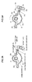
FIGS.2A and 2B are explanatory diagrams illustrating an operation of the tactile display device ofFig. 1 during a push operation; -
FIGS.3A and 3B are diagrams corresponding toFIGS.2A and 2B to show an operation of components of the tactile display device; -
FIGS.4A to 4C are explanatory diagrams illustrating an operation of the tactile display device during vibration feedback; -
FIGS.5A to 5C are diagrams corresponding toFIGS.4A to 4C to show an operation of components of the tactile display device; and -
FIGS.6A and 6B are explanatory diagrams illustrating a modification of the tactile display device. - A preferred embodiment of the invention will be specifically described below in conjunction with the appended drawings.
- In
FIG.1 , a typical operating device provided with a tactile display device and embodying the present invention is indicated generally by thereference numeral 1 and components of the operating device are schematically shown as an example. Theoperating device 1 is not specifically limited but is suitably used as a vehicle touch panel which outputs operation signals for controlling operation of an on-vehicle equipment, e.g., an air-conditioning system, an audio system or a navigation system, etc. - The
operating device 1 in the illustrated example is arranged on a periphery of a driver's seat such as a center console (not shown) in a vehicle and is connected to a display (not shown) via a wiring. - The
operating device 1 is configured as a remote control input device in which a touch operation of a touch panel by a finger of an operator causes, e.g., a touch sensor to detect a touch position on a surface of the touch panel and outputs a position detection signal corresponding to the detected position to select and determine an item button on a display. - As shown in
FIG.1 , theoperating device 1 is provided with atouch panel device 20 which can be push-operated and atactile display device 40 which presents tactile stimuli-operational feeling (haptic feeling) to a finger of an operator when thetouch panel device 20 is operated and receives an input. - Respective components of the
touch panel device 20 and thetactile display device 40 are fitted into aresin body 2 formed in a case shape which opens downward, as shown inFIG.1 . A resin cover body 3 covering the lower opening of thebody 2 is fastened and fixed by screws (not shown), thereby forming theoperating device 1 in which thetouch panel device 20 and thetactile display device 40 are integrated. - As shown in
FIG.1 , three (first to third)operating knobs body 2.Resin separators adjacent operating knobs 5. Afourth operating knob 6 is provided on another side of thebody 2. The first tofourth operating knobs push switches control board 7 can be respectively turned on and off viapushers - As shown in
FIG.1 , thetouch panel device 20 is assembled in a state that a rectangulartouch sensor substrate 23 is attached to a sheet-like touch panel 24 by a double-sided tape (not shown) between abase 21 having a rectangular shape in a plan view and aframe 22 having a frame shape. Thebase 21 and theframe 22 are formed of a resin material. A rectangular frame-shaped sealing member 25 is arranged so as to cover an outer periphery of thetouch panel device 20. The sealingmember 25 is electrically connected to a ground circuit of thecontrol board 7. - A recessed portion having a recessed shape is formed on an upper surface of the
base 21 and thetouch sensor substrate 23 is elastically held on a bottom surface of the recessed portion via aclick member 26, as shown inFIG.1 . Theclick member 26 is formed of a cylindrical rubber material displaceable with respect to thetouch panel 24 due to elastic deformation, and is formed so that an inner diameter on thetouch panel 24 side is larger than that on thebase 21 side. - The
frame 22 is formed of aframe portion 22a providing an opening on the upper surface, as shown inFIG.1 . Theframe portion 22a has a plate frame having a picture frame shape and a cylindrical wall portion extending from an edge of the inner periphery of the plate frame toward a housing portion. - As shown in
FIG.1 , thetouch sensor substrate 23 is connected to thetouch panel 24 via aconductive tape 27 as an electrically conductive material. - As shown in
FIG.1 , thetouch sensor substrate 23 is, e.g., a capacitive touch sensor for detecting capacitance and is connected, via a flexibleflat cable 28, to a connector (not shown) mounted on thecontrol board 7. Meanwhile, thetouch panel 24 is attached to the back side of the plate frame of theframe 22 by a double-sided tape 29 having sealing properties and is operably arranged such that an operation surface is exposed in an opening of theframe portion 22a of theframe 22. - Furthermore, as shown in
FIG.1 , plural elasticengaging pieces 21a...21a to be engaged with through-holes formed on thebody 2, a pair ofguide pieces body 2 and acoupling piece 21c as a coupling member moving in conjunction with reciprocating movement of thetouch panel 24 are formed on thebase 21 so as to respectively extend toward apush operation mechanism 30. - As shown in
FIG.1 , thepush operation mechanism 30 is provided with asupport shaft 31 rotatably fixed to thebody 2 and a linkingmember 32 which rotates integrally with one end of thesupport shaft 31. Adisc encoder 33 as a location sensor for detecting a position of thepush operation mechanism 30 and aholder 34 for holding thedisc encoder 33 are fixed to another end of thesupport shaft 31. - The
push operation mechanism 30 is further provided with astabilizer 35 for suppressing a tilting operation of thetouch panel 24 during the push operation, as shown inFIG.1 . Thestabilizer 35 is attached to the pair ofguide pieces 21b of thetouch panel device 20 at both ends respectively so as to cross with thesupport shaft 31, thereby suppressing the tilting operation around thesupport shaft 31. - A
torsion spring 36 is attached to the linkingmember 32, as shown inFIG.1 . - The
torsion spring 36 is configured to constantly bias the linkingmember 32 in one direction. Thesupport shaft 31 and thetorsion spring 36 are formed of a metal material and the linkingmember 32 is formed of a resin material. - As shown in
FIGS.2A to 3B , the linkingmember 32 has a doughnut-shapedbasal portion 32a having a support shaft-insertion hole 32b and a pair ofarm portions basal portion 32a. Acoupling pin 32d protrudes from thebasal portion 32a at an eccentric position. - The
coupling pin 32d of the linkingmember 32 is coupled to thecoupling piece 21c so as to be reciprocable (capable of reciprocating micro-motion) in apin locking hole 21d formed on thecoupling piece 21c of thebase 21 of thetouch panel device 20, as shown inFIGS.2A to 3B . Due to the coupling between thecoupling pin 32d and thecoupling piece 21c, the linkingmember 32 rotates forward and backward around thesupport shaft 31 of thepush operation mechanism 30 in conjunction with the push operation of thetouch panel device 20. A portion of thecoupling piece 21c opposite to thepin locking hole 21d is notched so as not to interfere with thetactile display device 40. - The main basic structure of the
operating device 1 in the present embodiment is thetactile display device 40 which provides both an operational feeling and a haptic feeling. Therefore, the operatingdevice 1 configured as described above is only a configuration example in the present embodiment, and shapes and structures of the components thereof are not limited to those of the illustrated example. - The
tactile display device 40 is provided with a tactile display means for presenting tactile stimuli-operational feeling to a finger of an operator via thepush operation mechanism 30. As shown inFIG.1 , the tactile display means is composed mainly of the linkingmember 32 of thepush operation mechanism 30 and adrive transmission mechanism 41. Thedrive transmission mechanism 41 is provided with a rotary drive means and a cam mechanism. - As shown in
FIG.1 , amotor 42 as the rotary drive means which can rotate forward and backward is held in ahousing 44 which is fastened and fixed to thebody 2 by screws (not shown). Themotor 42 is electrically connected to thecontrol board 7 via a terminal 45 having a cord electrically connected to thecontrol board 7 and also via aground clip 46 for discharging static electricity built up in themotor 42 to the ground circuit of thecontrol board 7. - Meanwhile, as shown in
FIG.1 , the cam mechanism is provided with acam plate 43 as a rotating cam member which is fixed to an output shaft of themotor 42. - If the
push operation mechanism 30 is continuously engaged with thetactile display device 40, the linkingmember 32 of thepush operation mechanism 30 and thecam plate 43 of thetactile display device 40 will act as a resisting force against the push operation of thepush operation mechanism 30 so as to impair the operation feeling thereof. Therefore, the continuous engagement is not preferred. - In the illustrated example, a structure to release the engagement between the linking
member 32 and thecam plate 43 is provided. As shown inFIGS.4A to 5C , thecam plate 43 is configured to be rotatable between an engagement position to transmit a drive force for presenting the operator with the tactile stimuli-operational feeling to the linkingmember 32 by allowing thecam plate 43 engage with the linkingmember 32 and a non-engagement position to allow the push operation of the user without having thecam plate 43 engage with the linkingmember 32. When it is not necessary to generate a haptic feeling, thetactile display device 40 is stopped at a position away from thepush operation mechanism 30. - As shown in
FIGS.4A to 5C , thecam plate 43 is a motion converting member which converts the oscillating rotary motion of themotor 42 into the reciprocating micro-motion of thetouch panel device 20. On an outer surface of thecam plate 43, afirst cam surface 43a and asecond cam surface 43b are formed so as to be symmetrical with respect to the output shaft of themotor 42. In the illustrated example, each of thefirst cam surface 43a and thesecond cam surface 43b is formed to have an involute curve. - The
first cam surface 43a serves as a stopper surface which abuts against thearm portion 32c of the linkingmember 32 on a cam plate-facing side to stop rotation of themotor 42, as shown inFIGS.2A to 3B . Thearm portion 32c is configured as a stopper which defines a stop position of thecam plate 43. On the other hand, thesecond cam surface 43b is configured to rotate at a predetermined angle while abutting against the linkingmember 32 at acam follower surface 32e of thearm portion 32c on the cam plate-facing side, as shown inFIGS.4A to 5C . - Next, an operation of the
tactile display device 40 configured as described above will be described. - When the
arm portion 32c of the linkingmember 32 of thepush operation mechanism 30 abuts against thefirst cam surface 43a of thecam plate 43 of thedrive transmission mechanism 41, the cam plate 43 (or the drive transmission mechanism 41) is at the non-engagement position not to transmit the drive force from themotor 42 to thepush operation mechanism 30, and the push operation of thetouch panel device 20 is allowed. - The push operation of the
touch panel device 20 causes thecoupling pin 32d of the linkingmember 32 to be pressed via thepin locking hole 21d of thecoupling piece 21c of thetouch panel device 20. This rotates the linkingmember 32 around thesupport shaft 31 in a direction indicated by an arrow inFIGS.2A to 3B . Thetouch panel device 20 moves with an operation stroke L1 but thecam plate 43 does not rotate since the linkingmember 32 moves without contacting thecam plate 43. - Therefore, even when the
arm portion 32c of the linkingmember 32 is engaged with thefirst cam surface 43a of thecam plate 43, the push-operation mode is maintained despite the rotation of the linkingmember 32 as long as thearm portion 32c contacts thefirst cam surface 43a since each of thearm portion 32c and thefirst cam surface 43a has a curved surface. - On the other hand, rotation of the
second cam surface 43b of thecam plate 43 at a predetermined angle while abutting against thearm portion 32c of the linkingmember 32 causes the linkingmember 32 to rotate around thesupport shaft 31 in a direction indicated by an arrow inFIGS.4A to 5C . This causes thecoupling piece 21c of thetouch panel device 20 to be pressed via thecoupling pin 32d of the linkingmember 32 and thetouch panel device 20 thus moves with an operation stroke L2. - When the
cam follower surface 32e of the linkingmember 32 contacts and rides over thesecond cam surface 43b of thecam plate 43, the cam plate (or the drive transmission mechanism 41) is at the engagement position to transmit the drive force from themotor 42 to thepush operation mechanism 30, which is in a tactile display mode for presenting tactile sensation to thetouch panel device 20. - This allows reciprocating micro-motion of the
coupling piece 21c of thetouch panel device 20 via thecoupling pin 32d of the linkingmember 32 with a varying pattern corresponding to the shape of thesecond cam surface 43b of thecam plate 43. Due to rotation of thecam plate 43 of thetactile display device 40 while abutting against thearm portion 32c of thepush operation mechanism 30, the forward and backward rotational force of themotor 42 is transmitted to the linkingmember 32 of thepush operation mechanism 30. - Then, the forward and backward rotational force of the linking
member 32 causes reciprocating micro-motion of thecoupling piece 21c of thetouch panel device 20, which vibrates thetouch panel 24. Due to the vibration of thetouch panel 24, feedback as tactile information in a vertical direction is given to the finger of the operator. - According to a touch signal, from the
touch panel device 20, indicating that the operation is performed by the finger of the operator, a control signal to repeat clockwise and counterclockwise rotations is output to themotor 42 and themotor 42 is rotationally driven in forward and backward rotational directions at a predetermined angle of rotation and a predetermined repetition cycle, and the tactile information is thereby obtained. - Use of the
operating device 1 configured as described above provides the following effects in addition to the above-mentioned effects. - It is possible to effectively obtain a configuration that allows a haptic feeling to be generated only in a necessary direction when tactile feedback is needed.
- It is possible to reduce a resisting force against the push operation of the
push operation mechanism 30 and a good operational feeling is thus obtained. - It is possible to reduce cogging torque of the
motor 42 and it is thus possible to realize drive with less impact noise and vibration, etc., associated with the cogging torque. - It is not necessary to provide a special mechanism to release the coupling between the linking
member 32 of thepush operation mechanism 30 and thecam plate 43 of thedrive transmission mechanism 41. Therefore, it is possible to avoid an increase in size and complexity of the entire operating device. - Since the
first cam surface 43a and thesecond cam surface 43b are symmetrical, an attaching direction of thecam plate 43 is not specified and it is thus possible to improve assembly properties. - Although a typical configuration example of the
operating device 1 of the invention has been described above in reference to one embodiment, it should be appreciated that various modifications are available as outlined below. - In
FIGS.6A and 6B , a modification of thetactile display device 40 is shown as a further non-limiting example. While thecam plate 43 of two-cam type having a pair of cams on both sides is provided in the above embodiment, the cam plate can be modified to comprise of single-cam type having a cam only on one side. It should be noted that substantially the same members as those in the embodiment are denoted by the same names and the same reference numerals inFIGS.6A and 6B . Therefore, the detailed description thereof will be omitted. - In
FIGS.6A and 6B , thefirst cam surface 43a is eliminated and only thesecond cam surface 43b is formed on the outer surface of thecam plate 43 of single-cam type. - The
second cam surface 43b is configured to rotate at a predetermined angle while abutting against thecam follower surface 32e of the linkingmember 32. A surface opposite to thesecond cam surface 43b serves as a stopper surface for stopping rotation of themotor 42 by abutting against astopper 8 which defines the stop position of thedrive transmission mechanism 41. - The
stopper 8 is a member provided to serve one of the functions of the linkingmember 32 in the embodiment and is fixed to, e.g., thebody 2, thecontrol board 7, themotor 42 orhousing 44. The shape, etc., of thestopper 8 can be appropriately determined depending on the layout position. A material suitable for thestopper 8 is, e.g., a rubber material such as silicon rubber. - In the
tactile display device 40 of the modification configured as described above, interference with thearm portion 32c of the linkingmember 32 when thecam plate 43 rotates can be effectively prevented by a simple structure. - Examples of further modifications are outlined below.
- The above-mentioned tactile display means is applicable not only to on-vehicle equipments but also to various terminal units, e.g., game consoles, personal computers and mobile phones, etc.
- It is possible to present tactile stimuli-operational feeling to a finger of an operator even in various switching devices not provided with a touch panel and the above-mentioned tactile display means is also applicable to, e.g., mouse devices, keyboards and control knobs, etc.
- The number, position and arrangement of the above-mentioned tactile display means can be appropriately selected depending on, e.g., the intended use, etc., to achieve the initial object of the invention.
- Although a typical embodiment, and various initial modifications have been described above, it should be appreciated that the invention is not limited to such details. Therefore, it should be noted that all of the features described in the embodiment, modifications and illustrations are not necessary to provide the advantages of the invention and the features can be provided in any appropriate combination with or without alternatives as required.
Claims (10)
- An operating device, comprising:a push operation mechanism to be push-operated by an operator; anda drive transmission mechanism to transmit a drive force for presenting the operator with a tactile stimuli-operational feeling via the push operation mechanism,wherein the push operation mechanism is configured to be engageable with the drive transmission mechanism, andwherein the drive transmission mechanism is configured to switch between a non-engagement position to allow the push operation of the user without being engaged with the push operation mechanism and an engagement position to allow the transmission of the drive force by being engaged with the push operation mechanism.
- The operating device according to Claim 1, wherein the push operation mechanism comprises a linking member supported so as to be rotatable in conjunction with a push operation of the push operation mechanism, and
wherein the drive transmission mechanism comprises a cam mechanism to switch between an engagement and a non-engagement with the linking member. - The operating device according to Claim 2, wherein the cam mechanism comprises a rotatable cam member arranged to be rotated by drive of a rotary drive means, and
wherein the linking member comprises a cam follower surface arranged to contact with a cam surface of the rotatable cam member in accordance with rotation of the cam member. - The operating device according to Claim 2, wherein the linking member comprises a coupling pin coupled to a coupling member provided on the push operation mechanism.
- The operating device according to Claim 2, further comprising a stopper that defines a stop position of the cam mechanism.
- The operating device according to Claim 5, wherein the stopper comprises the linking member.
- The operating device according to Claim 3, wherein the rotatable cam member comprises a first cam surface and a second cam surface that are formed symmetrical with respect to an output shaft of the rotatory drive means,
wherein the first cam surface is arranged to contact with the linking member to allow the push operation when the drive transmission mechanism is not engaged with the linking member, and
wherein the second cam surface is arranged to engage with the linking member to rotate in accordance with rotation of the rotary drive means when the drive transmission mechanism is engaged with the linking member. - The operating device according to Claim 3, further comprising a stopper to define a stop position of the rotatable cam member,
wherein the rotatable cam member comprises a first cam surface and a second cam member formed opposite the first cam surface,
wherein the first cam surface is arranged to contact with the stopper to allow the push operation when the drive transmission mechanism is not engaged with the linking member, and
wherein the second cam surface is arranged to engage with the linking member to rotate in accordance with rotation of the rotary drive means when the drive transmission mechanism is engaged with the linking member. - The operating device according to any one or more of Claims 1 to 8, wherein the push operation mechanism comprises a touch panel to be operated by the operator and a stabilizer to suppress a tilting operation of the touch panel during the push operation.
- The operating device according to Claim 9, wherein the push operation mechanism further comprises a linking member supported so as to be rotatable in conjunction with a push operation of the push operation mechanism, and
wherein the stabilizer is attached so as to cross with a rotation shaft of the linking member.
Applications Claiming Priority (1)
| Application Number | Priority Date | Filing Date | Title |
|---|---|---|---|
| JP2012229700A JP5236832B1 (en) | 2012-10-17 | 2012-10-17 | Operating device |
Publications (3)
| Publication Number | Publication Date |
|---|---|
| EP2736058A2 true EP2736058A2 (en) | 2014-05-28 |
| EP2736058A3 EP2736058A3 (en) | 2014-12-31 |
| EP2736058B1 EP2736058B1 (en) | 2017-09-27 |
Family
ID=49041715
Family Applications (1)
| Application Number | Title | Priority Date | Filing Date |
|---|---|---|---|
| EP13187867.0A Not-in-force EP2736058B1 (en) | 2012-10-17 | 2013-10-09 | Operating device |
Country Status (4)
| Country | Link |
|---|---|
| US (1) | US9811162B2 (en) |
| EP (1) | EP2736058B1 (en) |
| JP (1) | JP5236832B1 (en) |
| CN (1) | CN103777807B (en) |
Families Citing this family (6)
| Publication number | Priority date | Publication date | Assignee | Title |
|---|---|---|---|---|
| JP5650295B1 (en) * | 2013-09-12 | 2015-01-07 | 株式会社東海理化電機製作所 | Operating device |
| JP2016051303A (en) * | 2014-08-29 | 2016-04-11 | 株式会社東海理化電機製作所 | Power transmission mechanism and input device having the same |
| JP6465357B2 (en) * | 2015-07-13 | 2019-02-06 | 株式会社東海理化電機製作所 | Operating device |
| JP6105104B1 (en) | 2016-02-03 | 2017-03-29 | 株式会社東海理化電機製作所 | Flat cable wiring structure |
| DE102017111897B3 (en) | 2017-05-31 | 2018-09-06 | Trw Automotive Electronics & Components Gmbh | Operating device for a vehicle component and method for generating a feedback |
| CN113093925B (en) * | 2021-04-22 | 2024-10-15 | 深圳市源隆光学科技有限公司 | Mouse encoder and mouse |
Citations (1)
| Publication number | Priority date | Publication date | Assignee | Title |
|---|---|---|---|---|
| JP2010204741A (en) | 2009-02-27 | 2010-09-16 | Mitsumi Electric Co Ltd | Direction presentation device and terminal device |
Family Cites Families (14)
| Publication number | Priority date | Publication date | Assignee | Title |
|---|---|---|---|---|
| US5178265A (en) * | 1991-02-04 | 1993-01-12 | White Consolidated Industries, Inc. | Push-push snap switch |
| JPH07244558A (en) * | 1994-03-07 | 1995-09-19 | Sharp Corp | Tactile presentation device |
| JPH07325653A (en) * | 1994-05-31 | 1995-12-12 | Mitsubishi Electric Corp | Information input device |
| JP2002297314A (en) * | 2001-03-29 | 2002-10-11 | Japan Aviation Electronics Industry Ltd | Touch panel switch with click feeling |
| JP2004157749A (en) * | 2002-11-06 | 2004-06-03 | Seiko Epson Corp | Tactile presentation device |
| JP4323301B2 (en) * | 2003-01-30 | 2009-09-02 | アルプス電気株式会社 | Push switch device |
| JP2004349006A (en) * | 2003-05-20 | 2004-12-09 | Tokai Rika Co Ltd | Switch device |
| JP4619037B2 (en) * | 2004-02-20 | 2011-01-26 | 株式会社ニフコ | Lid opening / closing mechanism |
| CN100339549C (en) | 2004-02-20 | 2007-09-26 | 株式会社利富高 | Cover opening and closing mechanism |
| TWI262242B (en) | 2004-05-11 | 2006-09-21 | Nifco Inc | Cap opening/closing mechanism |
| DE102004054617B3 (en) * | 2004-11-11 | 2006-05-11 | Zf Friedrichshafen Ag | Actuation device with buttons |
| CN101681212A (en) * | 2007-06-14 | 2010-03-24 | 诺基亚公司 | Screen assembly |
| JP2009076434A (en) * | 2007-08-28 | 2009-04-09 | Tokai Rika Co Ltd | Joystick device, and vehicular screen operation system |
| US8633916B2 (en) * | 2009-12-10 | 2014-01-21 | Apple, Inc. | Touch pad with force sensors and actuator feedback |
-
2012
- 2012-10-17 JP JP2012229700A patent/JP5236832B1/en active Active
-
2013
- 2013-10-09 EP EP13187867.0A patent/EP2736058B1/en not_active Not-in-force
- 2013-10-10 CN CN201310470365.6A patent/CN103777807B/en not_active Expired - Fee Related
- 2013-10-11 US US14/051,718 patent/US9811162B2/en not_active Expired - Fee Related
Patent Citations (1)
| Publication number | Priority date | Publication date | Assignee | Title |
|---|---|---|---|---|
| JP2010204741A (en) | 2009-02-27 | 2010-09-16 | Mitsumi Electric Co Ltd | Direction presentation device and terminal device |
Also Published As
| Publication number | Publication date |
|---|---|
| CN103777807A (en) | 2014-05-07 |
| JP2014081809A (en) | 2014-05-08 |
| EP2736058B1 (en) | 2017-09-27 |
| US20140104209A1 (en) | 2014-04-17 |
| JP5236832B1 (en) | 2013-07-17 |
| EP2736058A3 (en) | 2014-12-31 |
| CN103777807B (en) | 2018-06-05 |
| US9811162B2 (en) | 2017-11-07 |
Similar Documents
| Publication | Publication Date | Title |
|---|---|---|
| US9811162B2 (en) | Operating device | |
| US9793076B2 (en) | Switching operating arrangement | |
| WO2013141354A1 (en) | Power generation switch apparatus | |
| US9454232B2 (en) | Operating device | |
| JP6063201B2 (en) | Operation device | |
| US6710707B2 (en) | Vehicle-mounted input device | |
| US9488988B2 (en) | Push operation mechanism having tactile feedback | |
| CN203055727U (en) | Multifunction switches and steering wheel | |
| US9832896B2 (en) | Flat cable wiring structure | |
| KR100835142B1 (en) | Scroll pushing switch module | |
| JP2014182718A (en) | Operation device | |
| JP2014101012A (en) | Operation device | |
| CN114906065B (en) | Vehicle display device | |
| JP2014081808A (en) | Manipulation device | |
| CN202150387U (en) | Key switch device | |
| JP2011028637A (en) | Force-sense imparting type input apparatus | |
| JP2015045363A (en) | Power transmission mechanism and input device equipped therewith | |
| KR101428114B1 (en) | Haptic apparatus having sub-button | |
| JP2006228620A (en) | Steering switching device | |
| JP2014154002A (en) | Operation device | |
| JP2001351473A (en) | Multi-directional operation type electronic component and electronic device using the same | |
| WO2018042712A1 (en) | Input device | |
| JP2017114225A (en) | Vehicular shift dial unit | |
| JP2016051303A (en) | Power transmission mechanism and input device having the same |
Legal Events
| Date | Code | Title | Description |
|---|---|---|---|
| PUAI | Public reference made under article 153(3) epc to a published international application that has entered the european phase |
Free format text: ORIGINAL CODE: 0009012 |
|
| 17P | Request for examination filed |
Effective date: 20131009 |
|
| AK | Designated contracting states |
Kind code of ref document: A2 Designated state(s): AL AT BE BG CH CY CZ DE DK EE ES FI FR GB GR HR HU IE IS IT LI LT LU LV MC MK MT NL NO PL PT RO RS SE SI SK SM TR |
|
| AX | Request for extension of the european patent |
Extension state: BA ME |
|
| PUAL | Search report despatched |
Free format text: ORIGINAL CODE: 0009013 |
|
| AK | Designated contracting states |
Kind code of ref document: A3 Designated state(s): AL AT BE BG CH CY CZ DE DK EE ES FI FR GB GR HR HU IE IS IT LI LT LU LV MC MK MT NL NO PL PT RO RS SE SI SK SM TR |
|
| AX | Request for extension of the european patent |
Extension state: BA ME |
|
| RIC1 | Information provided on ipc code assigned before grant |
Ipc: H01H 13/85 20060101AFI20141127BHEP Ipc: G06F 3/01 20060101ALI20141127BHEP |
|
| R17P | Request for examination filed (corrected) |
Effective date: 20150630 |
|
| RBV | Designated contracting states (corrected) |
Designated state(s): AL AT BE BG CH CY CZ DE DK EE ES FI FR GB GR HR HU IE IS IT LI LT LU LV MC MK MT NL NO PL PT RO RS SE SI SK SM TR |
|
| 17Q | First examination report despatched |
Effective date: 20160621 |
|
| REG | Reference to a national code |
Ref country code: DE Ref legal event code: R079 Ref document number: 602013027077 Country of ref document: DE Free format text: PREVIOUS MAIN CLASS: H01H0013850000 Ipc: H01H0003120000 |
|
| RIC1 | Information provided on ipc code assigned before grant |
Ipc: H01H 3/12 20060101AFI20170403BHEP Ipc: H01H 3/42 20060101ALI20170403BHEP Ipc: G06F 3/01 20060101ALI20170403BHEP Ipc: H01H 3/00 20060101ALI20170403BHEP |
|
| GRAP | Despatch of communication of intention to grant a patent |
Free format text: ORIGINAL CODE: EPIDOSNIGR1 |
|
| INTG | Intention to grant announced |
Effective date: 20170706 |
|
| GRAS | Grant fee paid |
Free format text: ORIGINAL CODE: EPIDOSNIGR3 |
|
| GRAA | (expected) grant |
Free format text: ORIGINAL CODE: 0009210 |
|
| AK | Designated contracting states |
Kind code of ref document: B1 Designated state(s): AL AT BE BG CH CY CZ DE DK EE ES FI FR GB GR HR HU IE IS IT LI LT LU LV MC MK MT NL NO PL PT RO RS SE SI SK SM TR |
|
| REG | Reference to a national code |
Ref country code: GB Ref legal event code: FG4D |
|
| REG | Reference to a national code |
Ref country code: CH Ref legal event code: EP |
|
| REG | Reference to a national code |
Ref country code: FR Ref legal event code: PLFP Year of fee payment: 5 |
|
| REG | Reference to a national code |
Ref country code: AT Ref legal event code: REF Ref document number: 932709 Country of ref document: AT Kind code of ref document: T Effective date: 20171015 |
|
| REG | Reference to a national code |
Ref country code: IE Ref legal event code: FG4D |
|
| REG | Reference to a national code |
Ref country code: DE Ref legal event code: R096 Ref document number: 602013027077 Country of ref document: DE |
|
| PG25 | Lapsed in a contracting state [announced via postgrant information from national office to epo] |
Ref country code: FI Free format text: LAPSE BECAUSE OF FAILURE TO SUBMIT A TRANSLATION OF THE DESCRIPTION OR TO PAY THE FEE WITHIN THE PRESCRIBED TIME-LIMIT Effective date: 20170927 Ref country code: LT Free format text: LAPSE BECAUSE OF FAILURE TO SUBMIT A TRANSLATION OF THE DESCRIPTION OR TO PAY THE FEE WITHIN THE PRESCRIBED TIME-LIMIT Effective date: 20170927 Ref country code: NO Free format text: LAPSE BECAUSE OF FAILURE TO SUBMIT A TRANSLATION OF THE DESCRIPTION OR TO PAY THE FEE WITHIN THE PRESCRIBED TIME-LIMIT Effective date: 20171227 Ref country code: SE Free format text: LAPSE BECAUSE OF FAILURE TO SUBMIT A TRANSLATION OF THE DESCRIPTION OR TO PAY THE FEE WITHIN THE PRESCRIBED TIME-LIMIT Effective date: 20170927 Ref country code: HR Free format text: LAPSE BECAUSE OF FAILURE TO SUBMIT A TRANSLATION OF THE DESCRIPTION OR TO PAY THE FEE WITHIN THE PRESCRIBED TIME-LIMIT Effective date: 20170927 |
|
| REG | Reference to a national code |
Ref country code: NL Ref legal event code: MP Effective date: 20170927 |
|
| REG | Reference to a national code |
Ref country code: LT Ref legal event code: MG4D |
|
| REG | Reference to a national code |
Ref country code: AT Ref legal event code: MK05 Ref document number: 932709 Country of ref document: AT Kind code of ref document: T Effective date: 20170927 |
|
| PG25 | Lapsed in a contracting state [announced via postgrant information from national office to epo] |
Ref country code: GR Free format text: LAPSE BECAUSE OF FAILURE TO SUBMIT A TRANSLATION OF THE DESCRIPTION OR TO PAY THE FEE WITHIN THE PRESCRIBED TIME-LIMIT Effective date: 20171228 Ref country code: LV Free format text: LAPSE BECAUSE OF FAILURE TO SUBMIT A TRANSLATION OF THE DESCRIPTION OR TO PAY THE FEE WITHIN THE PRESCRIBED TIME-LIMIT Effective date: 20170927 Ref country code: BG Free format text: LAPSE BECAUSE OF FAILURE TO SUBMIT A TRANSLATION OF THE DESCRIPTION OR TO PAY THE FEE WITHIN THE PRESCRIBED TIME-LIMIT Effective date: 20171227 Ref country code: RS Free format text: LAPSE BECAUSE OF FAILURE TO SUBMIT A TRANSLATION OF THE DESCRIPTION OR TO PAY THE FEE WITHIN THE PRESCRIBED TIME-LIMIT Effective date: 20170927 |
|
| PG25 | Lapsed in a contracting state [announced via postgrant information from national office to epo] |
Ref country code: NL Free format text: LAPSE BECAUSE OF FAILURE TO SUBMIT A TRANSLATION OF THE DESCRIPTION OR TO PAY THE FEE WITHIN THE PRESCRIBED TIME-LIMIT Effective date: 20170927 |
|
| PG25 | Lapsed in a contracting state [announced via postgrant information from national office to epo] |
Ref country code: ES Free format text: LAPSE BECAUSE OF FAILURE TO SUBMIT A TRANSLATION OF THE DESCRIPTION OR TO PAY THE FEE WITHIN THE PRESCRIBED TIME-LIMIT Effective date: 20170927 Ref country code: RO Free format text: LAPSE BECAUSE OF FAILURE TO SUBMIT A TRANSLATION OF THE DESCRIPTION OR TO PAY THE FEE WITHIN THE PRESCRIBED TIME-LIMIT Effective date: 20170927 Ref country code: CZ Free format text: LAPSE BECAUSE OF FAILURE TO SUBMIT A TRANSLATION OF THE DESCRIPTION OR TO PAY THE FEE WITHIN THE PRESCRIBED TIME-LIMIT Effective date: 20170927 |
|
| PG25 | Lapsed in a contracting state [announced via postgrant information from national office to epo] |
Ref country code: IT Free format text: LAPSE BECAUSE OF FAILURE TO SUBMIT A TRANSLATION OF THE DESCRIPTION OR TO PAY THE FEE WITHIN THE PRESCRIBED TIME-LIMIT Effective date: 20170927 Ref country code: IS Free format text: LAPSE BECAUSE OF FAILURE TO SUBMIT A TRANSLATION OF THE DESCRIPTION OR TO PAY THE FEE WITHIN THE PRESCRIBED TIME-LIMIT Effective date: 20180127 Ref country code: SM Free format text: LAPSE BECAUSE OF FAILURE TO SUBMIT A TRANSLATION OF THE DESCRIPTION OR TO PAY THE FEE WITHIN THE PRESCRIBED TIME-LIMIT Effective date: 20170927 Ref country code: AT Free format text: LAPSE BECAUSE OF FAILURE TO SUBMIT A TRANSLATION OF THE DESCRIPTION OR TO PAY THE FEE WITHIN THE PRESCRIBED TIME-LIMIT Effective date: 20170927 Ref country code: EE Free format text: LAPSE BECAUSE OF FAILURE TO SUBMIT A TRANSLATION OF THE DESCRIPTION OR TO PAY THE FEE WITHIN THE PRESCRIBED TIME-LIMIT Effective date: 20170927 Ref country code: SK Free format text: LAPSE BECAUSE OF FAILURE TO SUBMIT A TRANSLATION OF THE DESCRIPTION OR TO PAY THE FEE WITHIN THE PRESCRIBED TIME-LIMIT Effective date: 20170927 |
|
| REG | Reference to a national code |
Ref country code: CH Ref legal event code: PL |
|
| REG | Reference to a national code |
Ref country code: DE Ref legal event code: R097 Ref document number: 602013027077 Country of ref document: DE |
|
| PG25 | Lapsed in a contracting state [announced via postgrant information from national office to epo] |
Ref country code: MC Free format text: LAPSE BECAUSE OF FAILURE TO SUBMIT A TRANSLATION OF THE DESCRIPTION OR TO PAY THE FEE WITHIN THE PRESCRIBED TIME-LIMIT Effective date: 20170927 |
|
| REG | Reference to a national code |
Ref country code: IE Ref legal event code: MM4A |
|
| PG25 | Lapsed in a contracting state [announced via postgrant information from national office to epo] |
Ref country code: LI Free format text: LAPSE BECAUSE OF NON-PAYMENT OF DUE FEES Effective date: 20171031 Ref country code: CH Free format text: LAPSE BECAUSE OF NON-PAYMENT OF DUE FEES Effective date: 20171031 Ref country code: LU Free format text: LAPSE BECAUSE OF NON-PAYMENT OF DUE FEES Effective date: 20171009 Ref country code: DK Free format text: LAPSE BECAUSE OF FAILURE TO SUBMIT A TRANSLATION OF THE DESCRIPTION OR TO PAY THE FEE WITHIN THE PRESCRIBED TIME-LIMIT Effective date: 20170927 |
|
| PLBE | No opposition filed within time limit |
Free format text: ORIGINAL CODE: 0009261 |
|
| STAA | Information on the status of an ep patent application or granted ep patent |
Free format text: STATUS: NO OPPOSITION FILED WITHIN TIME LIMIT |
|
| REG | Reference to a national code |
Ref country code: BE Ref legal event code: MM Effective date: 20171031 |
|
| PG25 | Lapsed in a contracting state [announced via postgrant information from national office to epo] |
Ref country code: PL Free format text: LAPSE BECAUSE OF FAILURE TO SUBMIT A TRANSLATION OF THE DESCRIPTION OR TO PAY THE FEE WITHIN THE PRESCRIBED TIME-LIMIT Effective date: 20170927 Ref country code: BE Free format text: LAPSE BECAUSE OF NON-PAYMENT OF DUE FEES Effective date: 20171031 |
|
| 26N | No opposition filed |
Effective date: 20180628 |
|
| REG | Reference to a national code |
Ref country code: FR Ref legal event code: PLFP Year of fee payment: 6 |
|
| PG25 | Lapsed in a contracting state [announced via postgrant information from national office to epo] |
Ref country code: MT Free format text: LAPSE BECAUSE OF NON-PAYMENT OF DUE FEES Effective date: 20171009 |
|
| PG25 | Lapsed in a contracting state [announced via postgrant information from national office to epo] |
Ref country code: IE Free format text: LAPSE BECAUSE OF NON-PAYMENT OF DUE FEES Effective date: 20171009 |
|
| PG25 | Lapsed in a contracting state [announced via postgrant information from national office to epo] |
Ref country code: SI Free format text: LAPSE BECAUSE OF FAILURE TO SUBMIT A TRANSLATION OF THE DESCRIPTION OR TO PAY THE FEE WITHIN THE PRESCRIBED TIME-LIMIT Effective date: 20170927 |
|
| PG25 | Lapsed in a contracting state [announced via postgrant information from national office to epo] |
Ref country code: HU Free format text: LAPSE BECAUSE OF FAILURE TO SUBMIT A TRANSLATION OF THE DESCRIPTION OR TO PAY THE FEE WITHIN THE PRESCRIBED TIME-LIMIT; INVALID AB INITIO Effective date: 20131009 |
|
| PG25 | Lapsed in a contracting state [announced via postgrant information from national office to epo] |
Ref country code: CY Free format text: LAPSE BECAUSE OF NON-PAYMENT OF DUE FEES Effective date: 20170927 |
|
| PGFP | Annual fee paid to national office [announced via postgrant information from national office to epo] |
Ref country code: FR Payment date: 20190913 Year of fee payment: 7 |
|
| PG25 | Lapsed in a contracting state [announced via postgrant information from national office to epo] |
Ref country code: MK Free format text: LAPSE BECAUSE OF FAILURE TO SUBMIT A TRANSLATION OF THE DESCRIPTION OR TO PAY THE FEE WITHIN THE PRESCRIBED TIME-LIMIT Effective date: 20170927 |
|
| PG25 | Lapsed in a contracting state [announced via postgrant information from national office to epo] |
Ref country code: TR Free format text: LAPSE BECAUSE OF FAILURE TO SUBMIT A TRANSLATION OF THE DESCRIPTION OR TO PAY THE FEE WITHIN THE PRESCRIBED TIME-LIMIT Effective date: 20170927 |
|
| PGFP | Annual fee paid to national office [announced via postgrant information from national office to epo] |
Ref country code: GB Payment date: 20191011 Year of fee payment: 7 |
|
| PG25 | Lapsed in a contracting state [announced via postgrant information from national office to epo] |
Ref country code: PT Free format text: LAPSE BECAUSE OF FAILURE TO SUBMIT A TRANSLATION OF THE DESCRIPTION OR TO PAY THE FEE WITHIN THE PRESCRIBED TIME-LIMIT Effective date: 20170927 |
|
| PG25 | Lapsed in a contracting state [announced via postgrant information from national office to epo] |
Ref country code: AL Free format text: LAPSE BECAUSE OF FAILURE TO SUBMIT A TRANSLATION OF THE DESCRIPTION OR TO PAY THE FEE WITHIN THE PRESCRIBED TIME-LIMIT Effective date: 20170927 |
|
| PGFP | Annual fee paid to national office [announced via postgrant information from national office to epo] |
Ref country code: DE Payment date: 20200929 Year of fee payment: 8 |
|
| GBPC | Gb: european patent ceased through non-payment of renewal fee |
Effective date: 20201009 |
|
| PG25 | Lapsed in a contracting state [announced via postgrant information from national office to epo] |
Ref country code: FR Free format text: LAPSE BECAUSE OF NON-PAYMENT OF DUE FEES Effective date: 20201031 |
|
| PG25 | Lapsed in a contracting state [announced via postgrant information from national office to epo] |
Ref country code: GB Free format text: LAPSE BECAUSE OF NON-PAYMENT OF DUE FEES Effective date: 20201009 |
|
| REG | Reference to a national code |
Ref country code: DE Ref legal event code: R119 Ref document number: 602013027077 Country of ref document: DE |
|
| PG25 | Lapsed in a contracting state [announced via postgrant information from national office to epo] |
Ref country code: DE Free format text: LAPSE BECAUSE OF NON-PAYMENT OF DUE FEES Effective date: 20220503 |