EP2736029A2 - Methods and systems for determining an anchoring location of a marine vessel - Google Patents
Methods and systems for determining an anchoring location of a marine vessel Download PDFInfo
- Publication number
- EP2736029A2 EP2736029A2 EP13189075.8A EP13189075A EP2736029A2 EP 2736029 A2 EP2736029 A2 EP 2736029A2 EP 13189075 A EP13189075 A EP 13189075A EP 2736029 A2 EP2736029 A2 EP 2736029A2
- Authority
- EP
- European Patent Office
- Prior art keywords
- location
- marine vessel
- anchoring
- computing device
- location data
- Prior art date
- Legal status (The legal status is an assumption and is not a legal conclusion. Google has not performed a legal analysis and makes no representation as to the accuracy of the status listed.)
- Granted
Links
- 238000004873 anchoring Methods 0.000 title claims abstract description 74
- 238000000034 method Methods 0.000 title claims description 23
- 238000004891 communication Methods 0.000 claims description 5
- 230000000694 effects Effects 0.000 description 5
- XMQFTWRPUQYINF-UHFFFAOYSA-N bensulfuron-methyl Chemical compound COC(=O)C1=CC=CC=C1CS(=O)(=O)NC(=O)NC1=NC(OC)=CC(OC)=N1 XMQFTWRPUQYINF-UHFFFAOYSA-N 0.000 description 4
- 238000010586 diagram Methods 0.000 description 4
- 238000005516 engineering process Methods 0.000 description 4
- 238000010295 mobile communication Methods 0.000 description 2
- 230000009182 swimming Effects 0.000 description 2
- 238000010276 construction Methods 0.000 description 1
- 230000009189 diving Effects 0.000 description 1
- 230000007774 longterm Effects 0.000 description 1
- 230000005055 memory storage Effects 0.000 description 1
- 238000012986 modification Methods 0.000 description 1
- 230000004048 modification Effects 0.000 description 1
- 230000008520 organization Effects 0.000 description 1
- 230000003068 static effect Effects 0.000 description 1
- 230000007723 transport mechanism Effects 0.000 description 1
- XLYOFNOQVPJJNP-UHFFFAOYSA-N water Substances O XLYOFNOQVPJJNP-UHFFFAOYSA-N 0.000 description 1
Images


Classifications
-
- G—PHYSICS
- G01—MEASURING; TESTING
- G01C—MEASURING DISTANCES, LEVELS OR BEARINGS; SURVEYING; NAVIGATION; GYROSCOPIC INSTRUMENTS; PHOTOGRAMMETRY OR VIDEOGRAMMETRY
- G01C21/00—Navigation; Navigational instruments not provided for in groups G01C1/00 - G01C19/00
- G01C21/20—Instruments for performing navigational calculations
-
- G—PHYSICS
- G08—SIGNALLING
- G08G—TRAFFIC CONTROL SYSTEMS
- G08G3/00—Traffic control systems for marine craft
-
- B—PERFORMING OPERATIONS; TRANSPORTING
- B63—SHIPS OR OTHER WATERBORNE VESSELS; RELATED EQUIPMENT
- B63B—SHIPS OR OTHER WATERBORNE VESSELS; EQUIPMENT FOR SHIPPING
- B63B21/00—Tying-up; Shifting, towing, or pushing equipment; Anchoring
- B63B2021/003—Mooring or anchoring equipment, not otherwise provided for
- B63B2021/009—Drift monitors
Definitions
- Finding an anchoring berth is not supported by current technology. Lack of knowledge on this subject at best can make some situations frustrating and difficult, and at worse cause one to lose a boat or even a life. Many factors must be considered when determining where to anchor a boat, such as: shelter from wind, boat traffic, "swinging room" availability, a depth of water, and a terrain of the sea floor. However, even with current technology, finding a proper location to anchor a boat can be an extremely difficult and time consuming task, especially in areas a mariner is not familiar with.
- a system for detecting an anchoring location of a marine vessel includes a first computing device configured to capture location data of the marine vessel along a route of the marine vessel, and a second computing device.
- the second computing device including a memory area, a location component that determines location data of a marine vessel, and a processor.
- the processor is programmed to receive, from the first computing device, the location data of the marine vessel, determine, from the location data, a location along a route of the marine vessel that the marine vessel traveled a distance less than a maximum threshold distance over a predefined period of time, and identify the location along the route of the marine vessel that the marine vessel traveled a distance less than the anchoring threshold distance over the predefined period of time as an anchoring location.
- a computing device for determining an anchoring location of a marine vessel.
- the computing device includes a memory area, a location component that determines location data of the marine vessel; and a processor.
- the processor is programmed to receive the location data of the marine vessel, determine, from the location data, a location along a route of the marine vessel that the marine vessel traveled a distance less than a maximum threshold distance over a predefined period of time, and identify the location along the route of the marine vessel that the marine vessel traveled a distance less than the anchoring threshold distance over the predefined period of time as an anchoring location.
- a method for determining an anchoring location of a marine vessel includes receiving location data of the marine vessel, determining, from the location data, a location along a route of the marine vessel that the marine vessel traveled a distance less than a maximum threshold distance over a predefined period of time, and identifying the location along the route of the marine vessel that the marine vessel traveled a distance less than the anchoring threshold distance over the predefined period of time as an anchoring location.
- the processor is further programmed to provide, from the anchorage database, one or more anchorage locations within the defined radius of a particular location.
- the particular location is a current location of the second marine vessel.
- a method for determining an anchoring location of a marine vessel comprising:
- the location data is received from a computing device on the marine vessel and the computing device is a global positioning system (GPS) device.
- GPS global positioning system
- the location data comprises location coordinates of the marine vessel.
- the method comprises using an identification of the marine vessel is a factor in determining a length of the anchoring threshold distance.
- the anchoring location is within a predefined distance from an additional anchoring location, and wherein the method further comprises determining an average anchorage location based on a distance between the anchorage location and the additional anchorage location.
- the method further comprises storing the anchoring location in an anchorage database; and providing, from the anchorage database, one or more anchorage locations within the defined radius of a particular location.
- a Global Positioning System can be used by a mariner to identify a current location of a marine vessel (e.g., a boat or a ship). This GPS position information can be used for supporting other systems to identify a location of other marine vessels (AIS - Automatic Identification System), a route to a particular location (Chartplotter), ocean terrain (Chartplotter), and/or current weather conditions/forecasts for the location. GPS tracking systems may also be used to record a route a marine vessel has taken as well as record a time the marine vessel has spent at various locations along the route.
- the present disclosure enables an anchoring location of a marine vessel to be automatically determined from location data within the recorded/tracked route information associated with a marine vessel.
- an anchoring location of a marine vessel to be automatically determined from location data within the recorded/tracked route information associated with a marine vessel.
- one of ordinary skill in the art guided by the teachings herein will appreciate that while embodiments of the disclosure are illustrated and described herein with reference to using information captured by a GPS tracking system to determine an anchoring location of a marine vessel, aspects of the disclosure are operable with any system that performs the functionality illustrated and described herein, or its equivalent.
- An exemplary technical effect of the methods and systems described herein includes at least one of (a) receiving location data associated with a marine vessel; (b) determining, from the location data, a location along a route of the marine vessel that the marine vessel traveled a distance less than a maximum threshold distance over a predefined period of time; and (c) identifying the location along the route of the marine vessel that the marine vessel traveled a distance less than the anchoring threshold distance over the predefined period of time as an anchoring location.
- first computing device 102 is a mobile communication device with GPS capabilities for gathering the location data.
- first computing device 102 stores the location data in memory (not shown), which can later be accessed by a second computing device 104.
- second computing device 104 can access the location data from first computing device 102 in real time, for example, via a network 106.
- system 100 also includes an anchorage database 108 that stores anchorage locations.
- anchorage database 108 that stores anchorage locations.
- marine vessels can search anchorage database 108 for anchorage locations in a particular area, for example, a current location of a marine vessel or a particular location along a route the marine vessel.
- embodiments of the disclosure are illustrated and described herein with reference to a computing device or mobile computing device such as a laptop, embedded device, telephone, or a personal digital assistant, aspects of the disclosure are operable with any computing device that performs the functionality illustrated and described herein, or its equivalent.
- embodiments of the disclosure are operable with a desktop computing device, a laptop computer, and other portable and non-portable computing devices capable of providing navigation functionality.
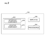
- second computing device 104 includes a memory area 202, at least one processor 204, and one or more optional displays 206 for displaying navigation information to a user.
- processor 204 is shown separate from memory area 202, embodiments of the disclosure contemplate that memory area 202 may be onboard processor 204, such as in some embedded systems.
- the diagram of Figure 2 is merely illustrative of an exemplary computing device that can be used in connection with one or more embodiments of the disclosure, and is not intended to be limiting in any way.
- Memory area 202 stores computer-executable components for determining and identifying anchoring locations of marine vessels.
- Exemplary components include, but are not limited to, an interface component 208 and a location component 210.
- Memory area 202 further stores location data such as location information associated with a route as well as a time spent at various locations along the route.
- the location information may include location coordinates for each location along a route of a marine vessel. As such, a detailed and accurate path of a marine vessel along a route can be stored in memory area 202.
- computer-executable instructions for determining an anchor location of a marine vessel may be stored and executed from a memory area remote from second computing device 104.
- instructions may be stored in a cloud service, a database, or other memory area accessible by second computing device 104. Such embodiments reduce the computational and storage burden on second computing device 104.
- interface component 208 receives, from first computing device 102, via a connection such as network 106, location data associated with the marine vessel.
- location component 210 determines location data of the marine vessel upon receipt of the location data from first computing device 102, which can either be accessed in real time or anytime thereafter.
- processor 204 is transformed into a special purpose microprocessor by executing computer-executable instructions or by otherwise being programmed.
- processor 204 is programmed with instructions such as is illustrated in and next described in Figure 3 .
- an exemplary flow chart illustrates a method for determining an anchoring location of a marine vessel.
- location data of a route of a marine vessel is captured by a first computing device (e.g., first computing device 102).
- first computing device 102 includes navigation functionality to record location data for a route of the marine vessel during a route of the marine vessel and storing the location data in a memory (not shown) of first computing device 102.
- the location data associated with the marine vessel is accessed by a second computing device (e.g., second computing device 104).
- Second computing device 104 may access the location data from first computing device 102 in real time, or anytime thereafter, for example, via a network 106.
- location component 210 determines, from the location data, a location along a route of the marine vessel that the marine vessel traveled a distance less than a maximum threshold distance over a predefined period of time.
- a first location identified in the location data of the marine vessel is shown at 402 and a second location identified in the location data of the marine vessel is shown at 404. Further, at 406, the location data provides a length 406 between first location 402 and the second location 404. As shown in Figure 4 , length 406 between first location 402 and second location 404 is less than a maximum threshold distance 408.
- maximum threshold distance 408 described herein is representative of a maximum distance a marine vessel travels when the marine vessel is anchored
- maximum threshold distance 408 may be a predefined distance, or a distance that is based on, for example, a type/size of the marine vessel associated with the location data, a length of an anchor line for the marine vessel, a depth of the ocean at anchor point 412, the wind, and/or a combination thereof.
- maximum threshold distance 408 may be static or dynamic.
- location component 210 not only determines, from the location data, a location along a route of the marine vessel that the marine vessel traveled a distance less than a maximum threshold distance, location component 210 also determines, from the location data, whether the marine vessel traveled a distance less than a maximum threshold distance over a predefined period of time.
- a marine vessel may be anchored for a variety of reasons/activities, such as, for swimming, scuba diving, fishing, and/or an overnight stay.
- each of these activities typically have different anchoring times with respect to how long each activity takes as well as a time of day for each activity.
- an anchoring of the marine vessel to be determined based in part on a defined length of time the marine vessel is within the maximum threshold distance, and the defined length of time may be a length of time representative of a short term anchoring (e.g., anchoring for swimming), or a long term anchoring (e.g., an overnight stay).
- the defined length of time may be within a particular time of the day/night. For example, to identify an anchoring representative of an overnight stay, location component 210 may only identify possible anchoring locations that a marine vessel travels a distance less than a maximum threshold distance between sunset and sunrise (e.g., from dawn to dusk).
- a location along the route of the marine vessel that the marine vessel traveled a distance less than the anchoring threshold distance over the predefined period of time is identified as an anchoring location (e.g., location 410 in Figure 4 ).
- the anchoring location is the average distance between first location 402 and second location 404 of the marine vessel.
- determining where the anchoring location is identified between first location 402 and second location 404 of the marine vessel is based on weather conditions (e.g., wind and waves) during a particular time period being analyzed, a length of the anchor line, depth of anchor point 412, and/or a type/size of the marine vessel.
- the anchoring location is stored in memory area 202.
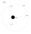
- a particular area may include pre-existing anchoring locations (e.g., anchoring locations 410, 502, and 504) stored in memory area 202.
- location component 210 may consolidate the anchoring locations within the minimum distance into an average anchorage location 508, and thereafter, memory area 202 is updated to show average anchorage location 508.
- a marine vessel can access anchorage database 108 to search/identify anchorage locations in a particular area. As such, marine vessels can search the anchorage database 108 for anchorage locations in a particular area, for example, a current location of a marine vessel or a particular location along a route the marine vessel.
- a marine vessel provides anchorage database 108 with a current location of the marine vessel. Thereafter, anchorage database 108 provides the marine vessel with one or more stored anchorage locations based on the current location of the marine vessel.
- a user searches anchorage database 108 for anchorage locations along a route of the marine vessel.
- a computer or mobile device such as described herein has one or more processors or processing units, system memory, and some form of computer readable media.
- computer readable media comprise computer storage media and communication media.
- Computer storage media include volatile and nonvolatile, removable and non-removable media implemented in any method or technology for storage of information such as computer readable instructions, data structures, program modules or other data.
- Communication media typically embody computer readable instructions, data structures, program modules, or other data in a modulated data signal such as a carrier wave or other transport mechanism and include any information delivery media. Combinations of any of the above are also included within the scope of computer readable media.
- the mobile device may operate in a networked environment using logical connections to one or more remote computers, such as a remote computer.
- a remote computer such as a remote computer.
- embodiments of the disclosure are operational with numerous other general purpose or special purpose computing system environments or configurations.
- the computing system environment is not intended to suggest any limitation as to the scope of use or functionality of any aspect of the disclosure.
- the computing system environment should not be interpreted as having any dependency or requirement relating to any one or combination of components illustrated in the exemplary operating environment.
- Examples of well known computing systems, environments, and/or configurations that may be suitable for use with aspects of the disclosure include, but are not limited to, personal computers, server computers, hand-held or laptop devices, multiprocessor systems, microprocessor-based systems, set top boxes, programmable consumer electronics, mobile telephones, network PCs, minicomputers, mainframe computers, distributed computing environments that include any of the above systems or devices, and the like.
- Embodiments of the disclosure may be described in the general context of computer-executable instructions, such as program modules, executed by one or more computers or other devices.
- the computer-executable instructions may be organized into one or more computer-executable components or modules.
- program modules include, but are not limited to, routines, programs, objects, components, and data structures that perform particular tasks or implement particular abstract data types.
- aspects of the disclosure may be implemented with any number and organization of such components or modules. For example, aspects of the disclosure are not limited to the specific computer-executable instructions or the specific components or modules illustrated in the figures and described herein.
- Other embodiments of the disclosure may include different computer-executable instructions or components having more or less functionality than illustrated and described herein.
- aspects of the disclosure may also be practiced in distributed computing environments where tasks are performed by remote processing devices that are linked through a communications network.
- program modules may be located in both local and remote computer storage media including memory storage devices.
Abstract
Description
- The present disclosure relates generally to determining an anchoring of a marine vessel, and more specifically, to a system and method for determining an anchoring location of a marine vessel based on location data of the marine vessel.
- Finding an anchoring berth is not supported by current technology. Lack of knowledge on this subject at best can make some situations frustrating and difficult, and at worse cause one to lose a boat or even a life. Many factors must be considered when determining where to anchor a boat, such as: shelter from wind, boat traffic, "swinging room" availability, a depth of water, and a terrain of the sea floor. However, even with current technology, finding a proper location to anchor a boat can be an extremely difficult and time consuming task, especially in areas a mariner is not familiar with.
- In one aspect, a system for detecting an anchoring location of a marine vessel is provided. The system includes a first computing device configured to capture location data of the marine vessel along a route of the marine vessel, and a second computing device. The second computing device including a memory area, a location component that determines location data of a marine vessel, and a processor. The processor is programmed to receive, from the first computing device, the location data of the marine vessel, determine, from the location data, a location along a route of the marine vessel that the marine vessel traveled a distance less than a maximum threshold distance over a predefined period of time, and identify the location along the route of the marine vessel that the marine vessel traveled a distance less than the anchoring threshold distance over the predefined period of time as an anchoring location.
- In another aspect, a computing device for determining an anchoring location of a marine vessel is provided. The computing device includes a memory area, a location component that determines location data of the marine vessel; and a processor. The processor is programmed to receive the location data of the marine vessel, determine, from the location data, a location along a route of the marine vessel that the marine vessel traveled a distance less than a maximum threshold distance over a predefined period of time, and identify the location along the route of the marine vessel that the marine vessel traveled a distance less than the anchoring threshold distance over the predefined period of time as an anchoring location.
- In yet another aspect, a method for determining an anchoring location of a marine vessel is provided. The method includes receiving location data of the marine vessel, determining, from the location data, a location along a route of the marine vessel that the marine vessel traveled a distance less than a maximum threshold distance over a predefined period of time, and identifying the location along the route of the marine vessel that the marine vessel traveled a distance less than the anchoring threshold distance over the predefined period of time as an anchoring location.
- The following paragraphs further describe some aspects of embodiments of the invention:
- In one embodiment, a system is provided for determining an anchoring location of a marine vessel, the system comprising:
- a first computing device configured to capture location data of the marine vessel along a route of the marine vessel; and
- a second computing device comprising:
- a memory area;
- a location component that determines location data of the marine vessel;
- an anchorage database configured to store anchorage locations and
- a processor programmed to:
- receive, from the first computing device, the location data of the marine vessel;
- determine, from the location data, that the marine vessel traveled a distance less than a maximum threshold distance over a predefined period of time; and
- identify the location that the marine vessel traveled a distance less than an anchoring threshold distance over the predefined period of time as an anchoring location.
- In a variant of the system, the processor is further programmed to provide, from the anchorage database, one or more anchorage locations within the defined radius of a particular location.
- In a second variant of the system, the particular location is a current location of the second marine vessel.
- In another embodiment, a method is provided for determining an anchoring location of a marine vessel, the method comprising:
- receiving location data associated with the marine vessel;
- determining, from the location data, a location that the marine vessel traveled a distance less than a maximum threshold distance over a predefined period of time; and
- identifying the location that the marine vessel traveled a distance less than the anchoring threshold distance over the predefined period of time as an anchoring location.
- In a variant of the method, the location data is received from a computing device on the marine vessel and the computing device is a global positioning system (GPS) device.
- In a second variant of the method, the location data comprises location coordinates of the marine vessel.
- In a third variant of the method, the method comprises using an identification of the marine vessel is a factor in determining a length of the anchoring threshold distance.
- In a fourth variant of the method, the anchoring location is within a predefined distance from an additional anchoring location, and wherein the method further comprises determining an average anchorage location based on a distance between the anchorage location and the additional anchorage location.
- In a fifth variant of the method, the method further comprises storing the anchoring location in an anchorage database; and providing, from the anchorage database, one or more anchorage locations within the defined radius of a particular location.
- The variants of the embodiments may be combined.
- The present disclosure is described in detail below with reference to the attached drawing figures.
-
Figure 1 is a block diagram of an exemplary system for use in determining an anchoring location of a marine vessel. -
Figure 2 is an exemplary block diagram of a computing device having a memory area storing components for determining an anchoring location of a marine vessel. -
Figure 3 is an exemplary flow chart illustrating a process for determining an anchoring location of a marine vessel. -
Figures 4 and5 are illustrative examples of possible anchoring locations determined by the systems and methods described herein. - A Global Positioning System (GPS) can be used by a mariner to identify a current location of a marine vessel (e.g., a boat or a ship). This GPS position information can be used for supporting other systems to identify a location of other marine vessels (AIS - Automatic Identification System), a route to a particular location (Chartplotter), ocean terrain (Chartplotter), and/or current weather conditions/forecasts for the location. GPS tracking systems may also be used to record a route a marine vessel has taken as well as record a time the marine vessel has spent at various locations along the route. However, even with the information provided by current technology, if a mariner does not have previous experience anchoring in a particular location or does not have documentation showing ideal anchoring locations, finding a proper location to anchor a marine vessel can be an extremely difficult and time consuming task. Further, unless a mariner chooses to document/identify various locations along the route the marine vessel has anchored, these anchoring locations are not captured in the record/tracking of the route.
- The present disclosure enables an anchoring location of a marine vessel to be automatically determined from location data within the recorded/tracked route information associated with a marine vessel. However, one of ordinary skill in the art guided by the teachings herein will appreciate that while embodiments of the disclosure are illustrated and described herein with reference to using information captured by a GPS tracking system to determine an anchoring location of a marine vessel, aspects of the disclosure are operable with any system that performs the functionality illustrated and described herein, or its equivalent.
- An exemplary technical effect of the methods and systems described herein includes at least one of (a) receiving location data associated with a marine vessel; (b) determining, from the location data, a location along a route of the marine vessel that the marine vessel traveled a distance less than a maximum threshold distance over a predefined period of time; and (c) identifying the location along the route of the marine vessel that the marine vessel traveled a distance less than the anchoring threshold distance over the predefined period of time as an anchoring location.
- With reference now to
Figure 1 , an exemplary block diagram of asystem 100 for determining an anchoring location of a marine vessel is provided. Embodiments of the disclosure enable a mobile communication device with navigation functionality, such as afirst computing device 102, to record location data for a route of, for example, a marine vessel. In some embodiments,first computing device 102 is a mobile communication device with GPS capabilities for gathering the location data. In some embodiments,first computing device 102 stores the location data in memory (not shown), which can later be accessed by asecond computing device 104. In other embodiments,second computing device 104 can access the location data fromfirst computing device 102 in real time, for example, via anetwork 106. In one embodiment,system 100 also includes ananchorage database 108 that stores anchorage locations. As such, marine vessels can searchanchorage database 108 for anchorage locations in a particular area, for example, a current location of a marine vessel or a particular location along a route the marine vessel. - While embodiments of the disclosure are illustrated and described herein with reference to a computing device or mobile computing device such as a laptop, embedded device, telephone, or a personal digital assistant, aspects of the disclosure are operable with any computing device that performs the functionality illustrated and described herein, or its equivalent. For example, embodiments of the disclosure are operable with a desktop computing device, a laptop computer, and other portable and non-portable computing devices capable of providing navigation functionality.
- Referring now to
Figure 2 ,second computing device 104 includes amemory area 202, at least oneprocessor 204, and one or moreoptional displays 206 for displaying navigation information to a user. Althoughprocessor 204 is shown separate frommemory area 202, embodiments of the disclosure contemplate thatmemory area 202 may beonboard processor 204, such as in some embedded systems. The diagram ofFigure 2 is merely illustrative of an exemplary computing device that can be used in connection with one or more embodiments of the disclosure, and is not intended to be limiting in any way. -
Memory area 202, or other computer-readable media, stores computer-executable components for determining and identifying anchoring locations of marine vessels. Exemplary components include, but are not limited to, aninterface component 208 and alocation component 210.Memory area 202 further stores location data such as location information associated with a route as well as a time spent at various locations along the route. For example, the location information may include location coordinates for each location along a route of a marine vessel. As such, a detailed and accurate path of a marine vessel along a route can be stored inmemory area 202. - In one embodiment, computer-executable instructions for determining an anchor location of a marine vessel may be stored and executed from a memory area remote from
second computing device 104. For example, instructions may be stored in a cloud service, a database, or other memory area accessible bysecond computing device 104. Such embodiments reduce the computational and storage burden onsecond computing device 104. - Referring again to
Figure 2 ,interface component 208 receives, fromfirst computing device 102, via a connection such asnetwork 106, location data associated with the marine vessel. In embodiments,location component 210 determines location data of the marine vessel upon receipt of the location data fromfirst computing device 102, which can either be accessed in real time or anytime thereafter. - In one embodiment,
processor 204 is transformed into a special purpose microprocessor by executing computer-executable instructions or by otherwise being programmed. For example,processor 204 is programmed with instructions such as is illustrated in and next described inFigure 3 . - With reference now to
Figure 3 , an exemplary flow chart illustrates a method for determining an anchoring location of a marine vessel. Initially, at 302, location data of a route of a marine vessel is captured by a first computing device (e.g., first computing device 102). In one embodiment,first computing device 102 includes navigation functionality to record location data for a route of the marine vessel during a route of the marine vessel and storing the location data in a memory (not shown) offirst computing device 102. - At 304, the location data associated with the marine vessel is accessed by a second computing device (e.g., second computing device 104).
Second computing device 104 may access the location data fromfirst computing device 102 in real time, or anytime thereafter, for example, via anetwork 106. At 306,second computing device 104, and more specifically,location component 210 determines, from the location data, a location along a route of the marine vessel that the marine vessel traveled a distance less than a maximum threshold distance over a predefined period of time. - For example, with reference now to
Figure 4 , a first location identified in the location data of the marine vessel is shown at 402 and a second location identified in the location data of the marine vessel is shown at 404. Further, at 406, the location data provides alength 406 betweenfirst location 402 and thesecond location 404. As shown inFigure 4 ,length 406 betweenfirst location 402 andsecond location 404 is less than amaximum threshold distance 408. Whilemaximum threshold distance 408 described herein is representative of a maximum distance a marine vessel travels when the marine vessel is anchored,maximum threshold distance 408 may be a predefined distance, or a distance that is based on, for example, a type/size of the marine vessel associated with the location data, a length of an anchor line for the marine vessel, a depth of the ocean atanchor point 412, the wind, and/or a combination thereof. Thus,maximum threshold distance 408 may be static or dynamic. - As explained above,
location component 210 not only determines, from the location data, a location along a route of the marine vessel that the marine vessel traveled a distance less than a maximum threshold distance,location component 210 also determines, from the location data, whether the marine vessel traveled a distance less than a maximum threshold distance over a predefined period of time. For example, a marine vessel may be anchored for a variety of reasons/activities, such as, for swimming, scuba diving, fishing, and/or an overnight stay. However, each of these activities typically have different anchoring times with respect to how long each activity takes as well as a time of day for each activity. Thus, embodiments of the present disclosure enable an anchoring of the marine vessel to be determined based in part on a defined length of time the marine vessel is within the maximum threshold distance, and the defined length of time may be a length of time representative of a short term anchoring (e.g., anchoring for swimming), or a long term anchoring (e.g., an overnight stay). In addition, the defined length of time may be within a particular time of the day/night. For example, to identify an anchoring representative of an overnight stay,location component 210 may only identify possible anchoring locations that a marine vessel travels a distance less than a maximum threshold distance between sunset and sunrise (e.g., from dawn to dusk). - With reference back to
Figure 3 , at 308, a location along the route of the marine vessel that the marine vessel traveled a distance less than the anchoring threshold distance over the predefined period of time is identified as an anchoring location (e.g.,location 410 inFigure 4 ). In one embodiment, the anchoring location is the average distance betweenfirst location 402 andsecond location 404 of the marine vessel. In another embodiment, determining where the anchoring location is identified betweenfirst location 402 andsecond location 404 of the marine vessel is based on weather conditions (e.g., wind and waves) during a particular time period being analyzed, a length of the anchor line, depth ofanchor point 412, and/or a type/size of the marine vessel. However, once the anchoring location is determined, at 310, the anchoring location is stored inmemory area 202. - With reference now to
Figure 5 , an illustrative example of a particular area having a plurality of determined anchoring locations is provided. That is, a particular area may include pre-existing anchoring locations (e.g., anchoringlocations memory area 202. In one embodiment, once a defined maximum number of anchoring locations are within a definedminimum radius 506 from one another,location component 210 may consolidate the anchoring locations within the minimum distance into anaverage anchorage location 508, and thereafter,memory area 202 is updated to showaverage anchorage location 508. - In one embodiment, a marine vessel can access
anchorage database 108 to search/identify anchorage locations in a particular area. As such, marine vessels can search theanchorage database 108 for anchorage locations in a particular area, for example, a current location of a marine vessel or a particular location along a route the marine vessel. In one embodiment, a marine vessel providesanchorage database 108 with a current location of the marine vessel. Thereafter,anchorage database 108 provides the marine vessel with one or more stored anchorage locations based on the current location of the marine vessel. In another embodiment, a user searchesanchorage database 108 for anchorage locations along a route of the marine vessel. In further embodiments, a user receives updates fromanchorage database 108 based on new anchorage locations determined by, for example,second computing device 104. As such, asanchorage database 108 is updated in real-time, the real-time updates are also provided to marine vessels/users based on, for example, a current location of the marine vessel or a route of the marine vessel. - A computer or mobile device such as described herein has one or more processors or processing units, system memory, and some form of computer readable media. By way of example and not limitation, computer readable media comprise computer storage media and communication media. Computer storage media include volatile and nonvolatile, removable and non-removable media implemented in any method or technology for storage of information such as computer readable instructions, data structures, program modules or other data. Communication media typically embody computer readable instructions, data structures, program modules, or other data in a modulated data signal such as a carrier wave or other transport mechanism and include any information delivery media. Combinations of any of the above are also included within the scope of computer readable media.
- The mobile device may operate in a networked environment using logical connections to one or more remote computers, such as a remote computer. Although described in connection with an exemplary computing system environment, embodiments of the disclosure are operational with numerous other general purpose or special purpose computing system environments or configurations. The computing system environment is not intended to suggest any limitation as to the scope of use or functionality of any aspect of the disclosure. Moreover, the computing system environment should not be interpreted as having any dependency or requirement relating to any one or combination of components illustrated in the exemplary operating environment. Examples of well known computing systems, environments, and/or configurations that may be suitable for use with aspects of the disclosure include, but are not limited to, personal computers, server computers, hand-held or laptop devices, multiprocessor systems, microprocessor-based systems, set top boxes, programmable consumer electronics, mobile telephones, network PCs, minicomputers, mainframe computers, distributed computing environments that include any of the above systems or devices, and the like.
- Embodiments of the disclosure may be described in the general context of computer-executable instructions, such as program modules, executed by one or more computers or other devices. The computer-executable instructions may be organized into one or more computer-executable components or modules. Generally, program modules include, but are not limited to, routines, programs, objects, components, and data structures that perform particular tasks or implement particular abstract data types. Aspects of the disclosure may be implemented with any number and organization of such components or modules. For example, aspects of the disclosure are not limited to the specific computer-executable instructions or the specific components or modules illustrated in the figures and described herein. Other embodiments of the disclosure may include different computer-executable instructions or components having more or less functionality than illustrated and described herein. Aspects of the disclosure may also be practiced in distributed computing environments where tasks are performed by remote processing devices that are linked through a communications network. In a distributed computing environment, program modules may be located in both local and remote computer storage media including memory storage devices.
- The order of execution or performance of the operations in embodiments of the disclosure illustrated and described herein is not essential, unless otherwise specified. That is, the operations may be performed in any order, unless otherwise specified, and embodiments of the disclosure may include additional or fewer operations than those disclosed herein. For example, it is contemplated that executing or performing a particular operation before, contemporaneously with, or after another operation is within the scope of aspects of the disclosure.
- When introducing elements of aspects of the disclosure or the embodiments thereof, the articles "a," "an," "the," and "said" are intended to mean that there are one or more of the elements. The terms "comprising," "including," and "having" are intended to be inclusive and mean that there may be additional elements other than the listed elements.
- Having described aspects of the disclosure in detail, it will be apparent that modifications and variations are possible without departing from the scope of aspects of the disclosure as defined in the appended claims. As various changes could be made in the above constructions, products, and methods without departing from the scope of aspects of the disclosure, it is intended that all matter contained in the above description and shown in the accompanying drawings shall be interpreted as illustrative and not in a limiting sense.
Claims (15)
- A system for determining an anchoring location of a marine vessel, the system comprising:a first computing device configured to capture location data of the marine vessel along a route of the marine vessel; anda second computing device comprising:a memory area;a location component that determines location data of the marine vessel; anda processor programmed to:receive, from the first computing device, the location data of the marine vessel;determine, from the location data, that the marine vessel traveled a distance less than a maximum threshold distance over a predefined period of time; andidentify the location that the marine vessel traveled a distance less than an anchoring threshold distance over the predefined period of time as an anchoring location.
- A system in accordance with Claim 1, wherein the first computing device includes a global positioning system (GPS) device.
- A system in accordance with any of Claims 1 or 2, wherein the location data comprises location coordinates of the marine vessel.
- A system in accordance with any of Claims 1-3, wherein the memory area comprises a length of an anchor line on the marine vessel; and
wherein the length of the anchor line is a factor in determining a length of the anchoring threshold distance. - A system in accordance with any of Claims 1-4, wherein the memory area comprises an identification of the marine vessel; and
wherein the identification of the marine vessel is a factor in determining a length of the anchoring threshold distance. - A system in accordance with any of Claim 1-5, wherein the anchoring location is within a predefined distance from an additional anchoring location; and
wherein the processor is further programmed to determine an average anchorage location based on a distance between the anchorage location and the additional anchorage location. - A system in accordance with any of Claims 1-6, further comprising an anchorage database configured to store anchorage locations.
- A computing device for determining an anchoring location of a marine vessel; the computing device comprising:a memory area;a location component that determines location data of the marine vessel; anda processor programmed to:receive the location data of the marine vessel;determine, from the location data, a location that the marine vessel traveled a distance less than a maximum threshold distance over a predefined period of time; andidentify the location of the marine vessel that the marine vessel traveled a distance less than an anchoring threshold distance over the predefined period of time as an anchoring location.
- A computing device in accordance with Claim 8, wherein the marine vessel comprises a communication device configured to provide the location data of the marine vessel along the route of the marine vessel.
- A computing device in accordance with Claim 9, wherein the communication device includes a global positioning system (GPS) device.
- A computing device in accordance with any of Claims 8-10, wherein the location data comprises location coordinates of the marine vessel.
- A computing device in accordance with any of Claims 8-11, wherein the memory area comprises an identification of the marine vessel; and
wherein the identification of the marine vessel is a factor in determining a length of the anchoring threshold distance. - A computing device in accordance with any of Claims 8-12, wherein the anchoring location is within a predefined distance from an additional anchoring location; and
wherein the processor is further programmed to determine an average anchorage location based on a distance between the anchorage location and the additional anchorage location. - A method for determining an anchoring location of a marine vessel, the method comprising:receiving location data associated with the marine vessel;determining, from the location data, a location that the marine vessel traveled a distance less than a maximum threshold distance over a predefined period of time; andidentifying the location that the marine vessel traveled a distance less than the anchoring threshold distance over the predefined period of time as an anchoring location.
- A method in accordance with Claim 14, wherein the location data is received from a computing device on the marine vessel.
Applications Claiming Priority (1)
| Application Number | Priority Date | Filing Date | Title |
|---|---|---|---|
| US13/683,846 US9188448B2 (en) | 2012-11-21 | 2012-11-21 | Methods and systems for determining an anchoring location of a marine vessel |
Publications (3)
| Publication Number | Publication Date |
|---|---|
| EP2736029A2 true EP2736029A2 (en) | 2014-05-28 |
| EP2736029A3 EP2736029A3 (en) | 2014-10-22 |
| EP2736029B1 EP2736029B1 (en) | 2021-03-17 |
Family
ID=49447973
Family Applications (1)
| Application Number | Title | Priority Date | Filing Date |
|---|---|---|---|
| EP13189075.8A Active EP2736029B1 (en) | 2012-11-21 | 2013-10-17 | Methods and systems for determining an anchoring location of a marine vessel |
Country Status (3)
| Country | Link |
|---|---|
| US (1) | US9188448B2 (en) |
| EP (1) | EP2736029B1 (en) |
| AU (1) | AU2013211568B2 (en) |
Families Citing this family (6)
| Publication number | Priority date | Publication date | Assignee | Title |
|---|---|---|---|---|
| US9188448B2 (en) * | 2012-11-21 | 2015-11-17 | The Boeing Company | Methods and systems for determining an anchoring location of a marine vessel |
| US9106810B1 (en) * | 2013-06-09 | 2015-08-11 | MTN Satellite Communications Inc. | Maritime safety systems for crew and passengers |
| US9834283B2 (en) * | 2014-07-31 | 2017-12-05 | Jkp Marine Pty Ltd | Mooring system and mooring buoy |
| WO2017204075A1 (en) * | 2016-05-26 | 2017-11-30 | 古野電気株式会社 | Signal processing device and radar device |
| JP7044018B2 (en) | 2018-09-07 | 2022-03-30 | トヨタ自動車株式会社 | Berthing control device, ship, berthing control method and berthing control program |
| US20230071338A1 (en) * | 2021-09-08 | 2023-03-09 | Sea Machines Robotics, Inc. | Navigation by mimic autonomy |
Family Cites Families (38)
| Publication number | Priority date | Publication date | Assignee | Title |
|---|---|---|---|---|
| IT1009574B (en) * | 1974-01-21 | 1976-12-20 | Saipem Spa | PERFECTED METHOD FOR THE POSITIONING OF A VESSEL IN PARTICULAR A DRILLING SHIP AND RELATED DEVICES |
| US4335520A (en) | 1980-09-22 | 1982-06-22 | The United States Of America As Represented By The Secretary Of The Navy | Survey spar system for precision offshore seafloor surveys |
| US4755947A (en) * | 1986-03-03 | 1988-07-05 | Parmac, Inc. | Monitor for and method of deploying anchor lines for off shore platforms |
| US5241920A (en) * | 1992-05-11 | 1993-09-07 | Richardson Lee E | Hook assembly for broken tow line retrieval and emergency marine towing |
| US5386368A (en) * | 1993-12-13 | 1995-01-31 | Johnson Fishing, Inc. | Apparatus for maintaining a boat in a fixed position |
| US5491636A (en) * | 1994-04-19 | 1996-02-13 | Glen E. Robertson | Anchorless boat positioning employing global positioning system |
| US5731788A (en) * | 1995-01-11 | 1998-03-24 | Trimble Navigation | Global positioning and communications system and method for race and start line management |
| DE19716684B4 (en) | 1997-04-21 | 2009-11-26 | Deep Blue Technology Ag | Anchor / anchor chain monitoring device |
| US6353813B1 (en) * | 1998-01-22 | 2002-03-05 | Microsoft Corporation | Method and apparatus, using attribute set harmonization and default attribute values, for matching entities and predicting an attribute of an entity |
| US20020049667A1 (en) * | 2000-09-07 | 2002-04-25 | Petro Vantage, Inc. | Computer method and apparatus for petroleum trading and logistics |
| US6678589B2 (en) * | 2002-04-08 | 2004-01-13 | Glen E. Robertson | Boat positioning and anchoring system |
| US6799528B1 (en) * | 2002-12-23 | 2004-10-05 | Joannes Raymond Mari Bekker | Portable dynamic positioning system with self-contained diesel hydraulic thrusters |
| JP4423364B2 (en) * | 2003-11-04 | 2010-03-03 | 財団法人新産業創造研究機構 | Anchorage monitoring system |
| US20070138347A1 (en) * | 2004-12-16 | 2007-06-21 | Ehlers Gregory A | System and method for providing information to an operator of a vehicle |
| US7469183B2 (en) * | 2005-01-24 | 2008-12-23 | International Business Machines Corporation | Navigating UAVs in formation |
| CH699530B1 (en) * | 2005-03-07 | 2010-03-31 | Klaus Kuhlgatz | System and method for the holistic farming of ships. |
| US7138945B1 (en) * | 2005-04-25 | 2006-11-21 | Uniden America Corporation | Method and apparatus for selecting a foghorn blast pattern |
| US7143712B1 (en) | 2005-06-17 | 2006-12-05 | Harvey Naslund | Anchor system |
| US7389735B2 (en) * | 2005-09-15 | 2008-06-24 | Yamaha Hatsudoki Kubushiki Kaisha | Docking supporting apparatus, and marine vessel including the apparatus |
| US7990263B2 (en) * | 2006-09-28 | 2011-08-02 | Beatty Street Properties, Inc. | Vector-based harbor scheduling |
| JP4221054B2 (en) * | 2006-10-31 | 2009-02-12 | 横浜ゴム株式会社 | Maneuvering and ship mooring support method and system |
| US8296001B1 (en) * | 2006-11-13 | 2012-10-23 | Garmin Switzerland Gmbh | Marine vessel navigation device, system and method |
| EP2089269B1 (en) * | 2006-11-30 | 2014-07-02 | Ab Volvo Penta | Safety system for marine vessels |
| US8335642B2 (en) * | 2007-05-11 | 2012-12-18 | The Boeing Company | Method and apparatus for displaying a symbol for a vehicle |
| US20090084302A1 (en) | 2007-09-28 | 2009-04-02 | Renaud Daran | Anchor monitoring system |
| US8082100B2 (en) * | 2007-10-19 | 2011-12-20 | Grace Ted V | Watercraft automation and aquatic effort data utilization |
| US8140262B2 (en) * | 2008-01-08 | 2012-03-20 | International Business Machines Corporation | Method to identify the vessel a container is loaded on |
| JP2011528433A (en) * | 2008-07-16 | 2011-11-17 | オートトークス エルティディ | Method for determining the relative position of a vehicle using vehicle communication |
| US20100023262A1 (en) * | 2008-07-24 | 2010-01-28 | Haney Mark T | Driftline navigation system |
| US7963242B2 (en) * | 2008-09-10 | 2011-06-21 | Raytheon Company | Anchor containing a self deploying mooring system and method of automatically deploying the mooring system from the anchor |
| US8549044B2 (en) * | 2009-09-17 | 2013-10-01 | Ydreams—Informatica, S.A. Edificio Ydreams | Range-centric contextual information systems and methods |
| US20110131050A1 (en) * | 2009-12-01 | 2011-06-02 | The Boeing Company | Harbor Berth Information System |
| ATE544666T1 (en) * | 2009-12-14 | 2012-02-15 | Converteam Technology Ltd | METHOD FOR CONTROLLING THE POSITION OF MOORED WATERCRAFT |
| US20110281478A1 (en) * | 2010-05-17 | 2011-11-17 | Benjamin Blumenthal | Systems, devices and methods for providing energy for ship propulsion |
| GB2509445A (en) * | 2011-09-14 | 2014-07-02 | Smart Ship Holdings Ltd | Allocating an area to a vehicle |
| US20130269583A1 (en) * | 2012-04-11 | 2013-10-17 | Mark Miller | Boat docking apparatus that maintains boat away from shallow waters |
| US9188448B2 (en) * | 2012-11-21 | 2015-11-17 | The Boeing Company | Methods and systems for determining an anchoring location of a marine vessel |
| GB2522004B (en) * | 2013-11-11 | 2021-05-19 | Tradenet Commercial Networking Ltd | A method and system for tracking shipping cargo |
-
2012
- 2012-11-21 US US13/683,846 patent/US9188448B2/en active Active
-
2013
- 2013-08-05 AU AU2013211568A patent/AU2013211568B2/en active Active
- 2013-10-17 EP EP13189075.8A patent/EP2736029B1/en active Active
Non-Patent Citations (1)
| Title |
|---|
| None |
Also Published As
| Publication number | Publication date |
|---|---|
| EP2736029A3 (en) | 2014-10-22 |
| AU2013211568B2 (en) | 2017-01-12 |
| AU2013211568A1 (en) | 2014-06-05 |
| EP2736029B1 (en) | 2021-03-17 |
| US9188448B2 (en) | 2015-11-17 |
| US20140142845A1 (en) | 2014-05-22 |
Similar Documents
| Publication | Publication Date | Title |
|---|---|---|
| EP2736029B1 (en) | Methods and systems for determining an anchoring location of a marine vessel | |
| US10178511B2 (en) | Vessel traffic management system | |
| US10480956B2 (en) | Method and system for displaying nowcasts along a route map | |
| KR101280066B1 (en) | Navigation system for vessel, information display method of vessel navigation, and recording medium thereof | |
| EP2981792A1 (en) | Method and system for displaying nowcasts along a route on a map | |
| CN102800215B (en) | AIS (Automatic Identification System)-data-based regional idle ship counting system and realization method thereof | |
| KR20110113029A (en) | A guidance system for docking of ship using position sensor | |
| KR102066841B1 (en) | Safety voyage system for small vessel with built-in ais | |
| US11143519B2 (en) | Indoor/outdoor transition points based on satellite signal strength | |
| JP2010190892A (en) | Marine radar system with three-dimensional memory | |
| CN108319264A (en) | Navigation control method, device | |
| CN109863529A (en) | The method for monitoring aquatic organism resource | |
| CN102521894B (en) | Automatic roll-calling system and method for special service task | |
| KR20200112610A (en) | Method and device of providing construction schedule of ocean construction | |
| US9817120B2 (en) | Fish tracker | |
| Dahlheim et al. | Temporal changes in abundance of harbor porpoise (Phocoena phocoena) inhabiting the inland waters of Southeast Alaska. | |
| US20210406128A1 (en) | Cloud storage system | |
| JP2016062231A (en) | Specification device and specification method | |
| CN111090112A (en) | GPS positioning point-taking method and device for equipment, terminal equipment and readable storage medium | |
| KR102063086B1 (en) | Safety voyage system for small vessel with built-in ais | |
| CN110363369B (en) | Ship shelving state judgment method, device, equipment and storage medium thereof | |
| JP2016189083A (en) | Management server and remote monitoring system | |
| US10365377B1 (en) | Apparatus and method for mobility mode state detection | |
| JP2023091838A (en) | Program, information processing device, information processing system and information processing method | |
| US20130060464A1 (en) | Method, Computer Program and Apparatus for Determining an Object in Sight |
Legal Events
| Date | Code | Title | Description |
|---|---|---|---|
| PUAI | Public reference made under article 153(3) epc to a published international application that has entered the european phase |
Free format text: ORIGINAL CODE: 0009012 |
|
| 17P | Request for examination filed |
Effective date: 20131017 |
|
| AK | Designated contracting states |
Kind code of ref document: A2 Designated state(s): AL AT BE BG CH CY CZ DE DK EE ES FI FR GB GR HR HU IE IS IT LI LT LU LV MC MK MT NL NO PL PT RO RS SE SI SK SM TR |
|
| AX | Request for extension of the european patent |
Extension state: BA ME |
|
| PUAL | Search report despatched |
Free format text: ORIGINAL CODE: 0009013 |
|
| AK | Designated contracting states |
Kind code of ref document: A3 Designated state(s): AL AT BE BG CH CY CZ DE DK EE ES FI FR GB GR HR HU IE IS IT LI LT LU LV MC MK MT NL NO PL PT RO RS SE SI SK SM TR |
|
| AX | Request for extension of the european patent |
Extension state: BA ME |
|
| RIC1 | Information provided on ipc code assigned before grant |
Ipc: G08G 3/00 20060101AFI20140916BHEP Ipc: G01C 21/20 20060101ALI20140916BHEP |
|
| STAA | Information on the status of an ep patent application or granted ep patent |
Free format text: STATUS: EXAMINATION IS IN PROGRESS |
|
| RIN1 | Information on inventor provided before grant (corrected) |
Inventor name: GAERTNER, MARCO FRANZ Inventor name: GODEHART, ANDREAS Inventor name: FUELLER, MERIAN Inventor name: LUTZ, ANDRE |
|
| 17Q | First examination report despatched |
Effective date: 20180502 |
|
| RIN1 | Information on inventor provided before grant (corrected) |
Inventor name: KINDERMANN, MERIAN Inventor name: GAERTNER, MARCO FRANZ Inventor name: LUTZ, ANDRE Inventor name: GODEHART, ANDREAS |
|
| GRAP | Despatch of communication of intention to grant a patent |
Free format text: ORIGINAL CODE: EPIDOSNIGR1 |
|
| STAA | Information on the status of an ep patent application or granted ep patent |
Free format text: STATUS: GRANT OF PATENT IS INTENDED |
|
| INTG | Intention to grant announced |
Effective date: 20201021 |
|
| RIN1 | Information on inventor provided before grant (corrected) |
Inventor name: GAERTNER, MARCO FRANZ Inventor name: GODEHART, ANDREAS Inventor name: LUTZ, ANDRE Inventor name: KINDERMANN, MERIAN |
|
| GRAS | Grant fee paid |
Free format text: ORIGINAL CODE: EPIDOSNIGR3 |
|
| GRAA | (expected) grant |
Free format text: ORIGINAL CODE: 0009210 |
|
| STAA | Information on the status of an ep patent application or granted ep patent |
Free format text: STATUS: THE PATENT HAS BEEN GRANTED |
|
| AK | Designated contracting states |
Kind code of ref document: B1 Designated state(s): AL AT BE BG CH CY CZ DE DK EE ES FI FR GB GR HR HU IE IS IT LI LT LU LV MC MK MT NL NO PL PT RO RS SE SI SK SM TR |
|
| REG | Reference to a national code |
Ref country code: GB Ref legal event code: FG4D |
|
| REG | Reference to a national code |
Ref country code: CH Ref legal event code: EP |
|
| REG | Reference to a national code |
Ref country code: DE Ref legal event code: R096 Ref document number: 602013076282 Country of ref document: DE |
|
| REG | Reference to a national code |
Ref country code: IE Ref legal event code: FG4D |
|
| REG | Reference to a national code |
Ref country code: AT Ref legal event code: REF Ref document number: 1372955 Country of ref document: AT Kind code of ref document: T Effective date: 20210415 |
|
| REG | Reference to a national code |
Ref country code: LT Ref legal event code: MG9D |
|
| PG25 | Lapsed in a contracting state [announced via postgrant information from national office to epo] |
Ref country code: FI Free format text: LAPSE BECAUSE OF FAILURE TO SUBMIT A TRANSLATION OF THE DESCRIPTION OR TO PAY THE FEE WITHIN THE PRESCRIBED TIME-LIMIT Effective date: 20210317 Ref country code: HR Free format text: LAPSE BECAUSE OF FAILURE TO SUBMIT A TRANSLATION OF THE DESCRIPTION OR TO PAY THE FEE WITHIN THE PRESCRIBED TIME-LIMIT Effective date: 20210317 Ref country code: GR Free format text: LAPSE BECAUSE OF FAILURE TO SUBMIT A TRANSLATION OF THE DESCRIPTION OR TO PAY THE FEE WITHIN THE PRESCRIBED TIME-LIMIT Effective date: 20210618 Ref country code: BG Free format text: LAPSE BECAUSE OF FAILURE TO SUBMIT A TRANSLATION OF THE DESCRIPTION OR TO PAY THE FEE WITHIN THE PRESCRIBED TIME-LIMIT Effective date: 20210617 Ref country code: NO Free format text: LAPSE BECAUSE OF FAILURE TO SUBMIT A TRANSLATION OF THE DESCRIPTION OR TO PAY THE FEE WITHIN THE PRESCRIBED TIME-LIMIT Effective date: 20210617 |
|
| REG | Reference to a national code |
Ref country code: AT Ref legal event code: MK05 Ref document number: 1372955 Country of ref document: AT Kind code of ref document: T Effective date: 20210317 |
|
| REG | Reference to a national code |
Ref country code: NL Ref legal event code: MP Effective date: 20210317 |
|
| PG25 | Lapsed in a contracting state [announced via postgrant information from national office to epo] |
Ref country code: SE Free format text: LAPSE BECAUSE OF FAILURE TO SUBMIT A TRANSLATION OF THE DESCRIPTION OR TO PAY THE FEE WITHIN THE PRESCRIBED TIME-LIMIT Effective date: 20210317 Ref country code: LV Free format text: LAPSE BECAUSE OF FAILURE TO SUBMIT A TRANSLATION OF THE DESCRIPTION OR TO PAY THE FEE WITHIN THE PRESCRIBED TIME-LIMIT Effective date: 20210317 Ref country code: RS Free format text: LAPSE BECAUSE OF FAILURE TO SUBMIT A TRANSLATION OF THE DESCRIPTION OR TO PAY THE FEE WITHIN THE PRESCRIBED TIME-LIMIT Effective date: 20210317 |
|
| PG25 | Lapsed in a contracting state [announced via postgrant information from national office to epo] |
Ref country code: NL Free format text: LAPSE BECAUSE OF FAILURE TO SUBMIT A TRANSLATION OF THE DESCRIPTION OR TO PAY THE FEE WITHIN THE PRESCRIBED TIME-LIMIT Effective date: 20210317 |
|
| PG25 | Lapsed in a contracting state [announced via postgrant information from national office to epo] |
Ref country code: EE Free format text: LAPSE BECAUSE OF FAILURE TO SUBMIT A TRANSLATION OF THE DESCRIPTION OR TO PAY THE FEE WITHIN THE PRESCRIBED TIME-LIMIT Effective date: 20210317 Ref country code: CZ Free format text: LAPSE BECAUSE OF FAILURE TO SUBMIT A TRANSLATION OF THE DESCRIPTION OR TO PAY THE FEE WITHIN THE PRESCRIBED TIME-LIMIT Effective date: 20210317 Ref country code: LT Free format text: LAPSE BECAUSE OF FAILURE TO SUBMIT A TRANSLATION OF THE DESCRIPTION OR TO PAY THE FEE WITHIN THE PRESCRIBED TIME-LIMIT Effective date: 20210317 Ref country code: AT Free format text: LAPSE BECAUSE OF FAILURE TO SUBMIT A TRANSLATION OF THE DESCRIPTION OR TO PAY THE FEE WITHIN THE PRESCRIBED TIME-LIMIT Effective date: 20210317 Ref country code: SM Free format text: LAPSE BECAUSE OF FAILURE TO SUBMIT A TRANSLATION OF THE DESCRIPTION OR TO PAY THE FEE WITHIN THE PRESCRIBED TIME-LIMIT Effective date: 20210317 |
|
| PG25 | Lapsed in a contracting state [announced via postgrant information from national office to epo] |
Ref country code: PL Free format text: LAPSE BECAUSE OF FAILURE TO SUBMIT A TRANSLATION OF THE DESCRIPTION OR TO PAY THE FEE WITHIN THE PRESCRIBED TIME-LIMIT Effective date: 20210317 Ref country code: PT Free format text: LAPSE BECAUSE OF FAILURE TO SUBMIT A TRANSLATION OF THE DESCRIPTION OR TO PAY THE FEE WITHIN THE PRESCRIBED TIME-LIMIT Effective date: 20210719 Ref country code: ES Free format text: LAPSE BECAUSE OF FAILURE TO SUBMIT A TRANSLATION OF THE DESCRIPTION OR TO PAY THE FEE WITHIN THE PRESCRIBED TIME-LIMIT Effective date: 20210317 Ref country code: SK Free format text: LAPSE BECAUSE OF FAILURE TO SUBMIT A TRANSLATION OF THE DESCRIPTION OR TO PAY THE FEE WITHIN THE PRESCRIBED TIME-LIMIT Effective date: 20210317 Ref country code: IS Free format text: LAPSE BECAUSE OF FAILURE TO SUBMIT A TRANSLATION OF THE DESCRIPTION OR TO PAY THE FEE WITHIN THE PRESCRIBED TIME-LIMIT Effective date: 20210717 Ref country code: RO Free format text: LAPSE BECAUSE OF FAILURE TO SUBMIT A TRANSLATION OF THE DESCRIPTION OR TO PAY THE FEE WITHIN THE PRESCRIBED TIME-LIMIT Effective date: 20210317 |
|
| REG | Reference to a national code |
Ref country code: DE Ref legal event code: R097 Ref document number: 602013076282 Country of ref document: DE |
|
| PLBE | No opposition filed within time limit |
Free format text: ORIGINAL CODE: 0009261 |
|
| STAA | Information on the status of an ep patent application or granted ep patent |
Free format text: STATUS: NO OPPOSITION FILED WITHIN TIME LIMIT |
|
| PG25 | Lapsed in a contracting state [announced via postgrant information from national office to epo] |
Ref country code: DK Free format text: LAPSE BECAUSE OF FAILURE TO SUBMIT A TRANSLATION OF THE DESCRIPTION OR TO PAY THE FEE WITHIN THE PRESCRIBED TIME-LIMIT Effective date: 20210317 Ref country code: AL Free format text: LAPSE BECAUSE OF FAILURE TO SUBMIT A TRANSLATION OF THE DESCRIPTION OR TO PAY THE FEE WITHIN THE PRESCRIBED TIME-LIMIT Effective date: 20210317 |
|
| 26N | No opposition filed |
Effective date: 20211220 |
|
| PG25 | Lapsed in a contracting state [announced via postgrant information from national office to epo] |
Ref country code: SI Free format text: LAPSE BECAUSE OF FAILURE TO SUBMIT A TRANSLATION OF THE DESCRIPTION OR TO PAY THE FEE WITHIN THE PRESCRIBED TIME-LIMIT Effective date: 20210317 |
|
| PG25 | Lapsed in a contracting state [announced via postgrant information from national office to epo] |
Ref country code: IT Free format text: LAPSE BECAUSE OF FAILURE TO SUBMIT A TRANSLATION OF THE DESCRIPTION OR TO PAY THE FEE WITHIN THE PRESCRIBED TIME-LIMIT Effective date: 20210317 |
|
| REG | Reference to a national code |
Ref country code: CH Ref legal event code: PL |
|
| PG25 | Lapsed in a contracting state [announced via postgrant information from national office to epo] |
Ref country code: IS Free format text: LAPSE BECAUSE OF FAILURE TO SUBMIT A TRANSLATION OF THE DESCRIPTION OR TO PAY THE FEE WITHIN THE PRESCRIBED TIME-LIMIT Effective date: 20210717 |
|
| REG | Reference to a national code |
Ref country code: BE Ref legal event code: MM Effective date: 20211031 |
|
| PG25 | Lapsed in a contracting state [announced via postgrant information from national office to epo] |
Ref country code: MC Free format text: LAPSE BECAUSE OF FAILURE TO SUBMIT A TRANSLATION OF THE DESCRIPTION OR TO PAY THE FEE WITHIN THE PRESCRIBED TIME-LIMIT Effective date: 20210317 |
|
| PG25 | Lapsed in a contracting state [announced via postgrant information from national office to epo] |
Ref country code: LU Free format text: LAPSE BECAUSE OF NON-PAYMENT OF DUE FEES Effective date: 20211017 Ref country code: BE Free format text: LAPSE BECAUSE OF NON-PAYMENT OF DUE FEES Effective date: 20211031 |
|
| PG25 | Lapsed in a contracting state [announced via postgrant information from national office to epo] |
Ref country code: LI Free format text: LAPSE BECAUSE OF NON-PAYMENT OF DUE FEES Effective date: 20211031 Ref country code: CH Free format text: LAPSE BECAUSE OF NON-PAYMENT OF DUE FEES Effective date: 20211031 |
|
| PG25 | Lapsed in a contracting state [announced via postgrant information from national office to epo] |
Ref country code: IE Free format text: LAPSE BECAUSE OF NON-PAYMENT OF DUE FEES Effective date: 20211017 |
|
| PG25 | Lapsed in a contracting state [announced via postgrant information from national office to epo] |
Ref country code: HU Free format text: LAPSE BECAUSE OF FAILURE TO SUBMIT A TRANSLATION OF THE DESCRIPTION OR TO PAY THE FEE WITHIN THE PRESCRIBED TIME-LIMIT; INVALID AB INITIO Effective date: 20131017 |
|
| P01 | Opt-out of the competence of the unified patent court (upc) registered |
Effective date: 20230516 |
|
| PG25 | Lapsed in a contracting state [announced via postgrant information from national office to epo] |
Ref country code: CY Free format text: LAPSE BECAUSE OF FAILURE TO SUBMIT A TRANSLATION OF THE DESCRIPTION OR TO PAY THE FEE WITHIN THE PRESCRIBED TIME-LIMIT Effective date: 20210317 |
|
| PGFP | Annual fee paid to national office [announced via postgrant information from national office to epo] |
Ref country code: GB Payment date: 20231027 Year of fee payment: 11 |
|
| PGFP | Annual fee paid to national office [announced via postgrant information from national office to epo] |
Ref country code: FR Payment date: 20231025 Year of fee payment: 11 Ref country code: DE Payment date: 20231027 Year of fee payment: 11 |
|
| PG25 | Lapsed in a contracting state [announced via postgrant information from national office to epo] |
Ref country code: MK Free format text: LAPSE BECAUSE OF FAILURE TO SUBMIT A TRANSLATION OF THE DESCRIPTION OR TO PAY THE FEE WITHIN THE PRESCRIBED TIME-LIMIT Effective date: 20210317 |