EP2735901A1 - Bildgebungsgerät mit mehreren Erkennungseinheiten, die auf einer Brennebene angeordnet sind - Google Patents
Bildgebungsgerät mit mehreren Erkennungseinheiten, die auf einer Brennebene angeordnet sind Download PDFInfo
- Publication number
- EP2735901A1 EP2735901A1 EP13193444.0A EP13193444A EP2735901A1 EP 2735901 A1 EP2735901 A1 EP 2735901A1 EP 13193444 A EP13193444 A EP 13193444A EP 2735901 A1 EP2735901 A1 EP 2735901A1
- Authority
- EP
- European Patent Office
- Prior art keywords
- detector
- detection
- detectors
- main
- additional
- Prior art date
- Legal status (The legal status is an assumption and is not a legal conclusion. Google has not performed a legal analysis and makes no representation as to the accuracy of the status listed.)
- Granted
Links
- 238000003384 imaging method Methods 0.000 title claims abstract description 52
- 238000001514 detection method Methods 0.000 title claims description 102
- 230000000712 assembly Effects 0.000 claims abstract description 47
- 238000000429 assembly Methods 0.000 claims abstract description 47
- 239000000758 substrate Substances 0.000 claims abstract description 33
- 238000000034 method Methods 0.000 claims abstract description 4
- 230000004907 flux Effects 0.000 claims description 26
- 230000003595 spectral effect Effects 0.000 claims description 25
- 230000002457 bidirectional effect Effects 0.000 claims description 23
- 230000005540 biological transmission Effects 0.000 claims description 19
- 238000001914 filtration Methods 0.000 claims 3
- 230000003287 optical effect Effects 0.000 abstract description 12
- 238000006073 displacement reaction Methods 0.000 description 6
- 230000010354 integration Effects 0.000 description 4
- 238000004519 manufacturing process Methods 0.000 description 3
- 230000037361 pathway Effects 0.000 description 2
- 230000002093 peripheral effect Effects 0.000 description 2
- 238000000926 separation method Methods 0.000 description 2
- 101001128138 Homo sapiens NACHT, LRR and PYD domains-containing protein 2 Proteins 0.000 description 1
- 101001128135 Homo sapiens NACHT, LRR and PYD domains-containing protein 4 Proteins 0.000 description 1
- 101001109455 Homo sapiens NACHT, LRR and PYD domains-containing protein 6 Proteins 0.000 description 1
- 101000982939 Homo sapiens PAN2-PAN3 deadenylation complex catalytic subunit PAN2 Proteins 0.000 description 1
- 101001113056 Homo sapiens PAN2-PAN3 deadenylation complex subunit PAN3 Proteins 0.000 description 1
- 101000742934 Homo sapiens Retinol dehydrogenase 14 Proteins 0.000 description 1
- 102100031897 NACHT, LRR and PYD domains-containing protein 2 Human genes 0.000 description 1
- 102100031898 NACHT, LRR and PYD domains-containing protein 4 Human genes 0.000 description 1
- 102100022696 NACHT, LRR and PYD domains-containing protein 6 Human genes 0.000 description 1
- 238000009825 accumulation Methods 0.000 description 1
- 230000000295 complement effect Effects 0.000 description 1
- 230000002950 deficient Effects 0.000 description 1
- 230000023077 detection of light stimulus Effects 0.000 description 1
- 238000010586 diagram Methods 0.000 description 1
- 230000010339 dilation Effects 0.000 description 1
- 239000006185 dispersion Substances 0.000 description 1
- 239000011159 matrix material Substances 0.000 description 1
- 230000008520 organization Effects 0.000 description 1
- 230000009467 reduction Effects 0.000 description 1
- 230000035945 sensitivity Effects 0.000 description 1
- 230000001360 synchronised effect Effects 0.000 description 1
Images


Classifications
-
- G—PHYSICS
- G01—MEASURING; TESTING
- G01C—MEASURING DISTANCES, LEVELS OR BEARINGS; SURVEYING; NAVIGATION; GYROSCOPIC INSTRUMENTS; PHOTOGRAMMETRY OR VIDEOGRAMMETRY
- G01C11/00—Photogrammetry or videogrammetry, e.g. stereogrammetry; Photographic surveying
- G01C11/02—Picture taking arrangements specially adapted for photogrammetry or photographic surveying, e.g. controlling overlapping of pictures
-
- G—PHYSICS
- G02—OPTICS
- G02B—OPTICAL ELEMENTS, SYSTEMS OR APPARATUS
- G02B27/00—Optical systems or apparatus not provided for by any of the groups G02B1/00 - G02B26/00, G02B30/00
- G02B27/10—Beam splitting or combining systems
- G02B27/1006—Beam splitting or combining systems for splitting or combining different wavelengths
- G02B27/1013—Beam splitting or combining systems for splitting or combining different wavelengths for colour or multispectral image sensors, e.g. splitting an image into monochromatic image components on respective sensors
-
- G—PHYSICS
- G01—MEASURING; TESTING
- G01J—MEASUREMENT OF INTENSITY, VELOCITY, SPECTRAL CONTENT, POLARISATION, PHASE OR PULSE CHARACTERISTICS OF INFRARED, VISIBLE OR ULTRAVIOLET LIGHT; COLORIMETRY; RADIATION PYROMETRY
- G01J3/00—Spectrometry; Spectrophotometry; Monochromators; Measuring colours
- G01J3/28—Investigating the spectrum
- G01J3/2803—Investigating the spectrum using photoelectric array detector
-
- G—PHYSICS
- G01—MEASURING; TESTING
- G01J—MEASUREMENT OF INTENSITY, VELOCITY, SPECTRAL CONTENT, POLARISATION, PHASE OR PULSE CHARACTERISTICS OF INFRARED, VISIBLE OR ULTRAVIOLET LIGHT; COLORIMETRY; RADIATION PYROMETRY
- G01J3/00—Spectrometry; Spectrophotometry; Monochromators; Measuring colours
- G01J3/28—Investigating the spectrum
- G01J3/2823—Imaging spectrometer
-
- G—PHYSICS
- G02—OPTICS
- G02B—OPTICAL ELEMENTS, SYSTEMS OR APPARATUS
- G02B27/00—Optical systems or apparatus not provided for by any of the groups G02B1/00 - G02B26/00, G02B30/00
- G02B27/10—Beam splitting or combining systems
- G02B27/1066—Beam splitting or combining systems for enhancing image performance, like resolution, pixel numbers, dual magnifications or dynamic range, by tiling, slicing or overlapping fields of view
-
- H—ELECTRICITY
- H04—ELECTRIC COMMUNICATION TECHNIQUE
- H04N—PICTORIAL COMMUNICATION, e.g. TELEVISION
- H04N13/00—Stereoscopic video systems; Multi-view video systems; Details thereof
- H04N13/20—Image signal generators
- H04N13/204—Image signal generators using stereoscopic image cameras
- H04N13/207—Image signal generators using stereoscopic image cameras using a single 2D image sensor
- H04N13/214—Image signal generators using stereoscopic image cameras using a single 2D image sensor using spectral multiplexing
-
- H—ELECTRICITY
- H04—ELECTRIC COMMUNICATION TECHNIQUE
- H04N—PICTORIAL COMMUNICATION, e.g. TELEVISION
- H04N23/00—Cameras or camera modules comprising electronic image sensors; Control thereof
- H04N23/60—Control of cameras or camera modules
- H04N23/667—Camera operation mode switching, e.g. between still and video, sport and normal or high- and low-resolution modes
-
- H—ELECTRICITY
- H04—ELECTRIC COMMUNICATION TECHNIQUE
- H04N—PICTORIAL COMMUNICATION, e.g. TELEVISION
- H04N25/00—Circuitry of solid-state image sensors [SSIS]; Control thereof
- H04N25/10—Circuitry of solid-state image sensors [SSIS]; Control thereof for transforming different wavelengths into image signals
- H04N25/11—Arrangement of colour filter arrays [CFA]; Filter mosaics
- H04N25/13—Arrangement of colour filter arrays [CFA]; Filter mosaics characterised by the spectral characteristics of the filter elements
- H04N25/133—Arrangement of colour filter arrays [CFA]; Filter mosaics characterised by the spectral characteristics of the filter elements including elements passing panchromatic light, e.g. filters passing white light
-
- H—ELECTRICITY
- H04—ELECTRIC COMMUNICATION TECHNIQUE
- H04N—PICTORIAL COMMUNICATION, e.g. TELEVISION
- H04N25/00—Circuitry of solid-state image sensors [SSIS]; Control thereof
- H04N25/70—SSIS architectures; Circuits associated therewith
-
- H—ELECTRICITY
- H04—ELECTRIC COMMUNICATION TECHNIQUE
- H04N—PICTORIAL COMMUNICATION, e.g. TELEVISION
- H04N25/00—Circuitry of solid-state image sensors [SSIS]; Control thereof
- H04N25/70—SSIS architectures; Circuits associated therewith
- H04N25/701—Line sensors
-
- H—ELECTRICITY
- H04—ELECTRIC COMMUNICATION TECHNIQUE
- H04N—PICTORIAL COMMUNICATION, e.g. TELEVISION
- H04N3/00—Scanning details of television systems; Combination thereof with generation of supply voltages
- H04N3/10—Scanning details of television systems; Combination thereof with generation of supply voltages by means not exclusively optical-mechanical
- H04N3/14—Scanning details of television systems; Combination thereof with generation of supply voltages by means not exclusively optical-mechanical by means of electrically scanned solid-state devices
- H04N3/15—Scanning details of television systems; Combination thereof with generation of supply voltages by means not exclusively optical-mechanical by means of electrically scanned solid-state devices for picture signal generation
- H04N3/1581—Scanning details of television systems; Combination thereof with generation of supply voltages by means not exclusively optical-mechanical by means of electrically scanned solid-state devices for picture signal generation using linear image-sensor
-
- G—PHYSICS
- G01—MEASURING; TESTING
- G01J—MEASUREMENT OF INTENSITY, VELOCITY, SPECTRAL CONTENT, POLARISATION, PHASE OR PULSE CHARACTERISTICS OF INFRARED, VISIBLE OR ULTRAVIOLET LIGHT; COLORIMETRY; RADIATION PYROMETRY
- G01J3/00—Spectrometry; Spectrophotometry; Monochromators; Measuring colours
- G01J3/28—Investigating the spectrum
- G01J3/2823—Imaging spectrometer
- G01J2003/2826—Multispectral imaging, e.g. filter imaging
-
- H—ELECTRICITY
- H04—ELECTRIC COMMUNICATION TECHNIQUE
- H04N—PICTORIAL COMMUNICATION, e.g. TELEVISION
- H04N13/00—Stereoscopic video systems; Multi-view video systems; Details thereof
- H04N13/20—Image signal generators
- H04N13/204—Image signal generators using stereoscopic image cameras
- H04N13/207—Image signal generators using stereoscopic image cameras using a single 2D image sensor
- H04N13/218—Image signal generators using stereoscopic image cameras using a single 2D image sensor using spatial multiplexing
Definitions
- the present invention relates to an imaging apparatus with several detection sets that are arranged in the same focal plane.
- the design of an imaging apparatus for a space observation mission depends on the mission objectives, as well as the satellite orbit or the altitude of the aircraft on which the aircraft is embarked.
- the observation of the Earth from a satellite in low circular orbit can be performed during the same passage of the satellite within several adjacent bands parallel to the direction of travel of the satellite.
- Low orbit means an orbit for which the satellite altitude is between 400 km (km) and 1000 km.
- Each observation band is called sub-mowed in the jargon of the skilled person. It corresponds approximately to a line of photosensitive elements of one or more detector (s) which is (are) used at the same time to capture the image of a transverse segment of the sub-swath.
- the total scan then results from a combination between the continuous acquisition of images within longitudinal segments of sub-mowing, and transverse offsets of the line of sight to move from one sub-mowing to another.
- Such a mode of scanning is called "push-broom", and allows to capture in image a total band of terrestrial surface, called swath, whose width is approximately equal to that of a sub-swath, multiplied by the number of sub -fauchées.
- a swath width of 20 to 30 km can be obtained with a ground-based resolution (GSD) which is less than 1 m (meter), for example of the order of 0 , 5 m.
- GSD ground-based resolution
- a first push-broom scanning mode the image acquisitions for two longitudinal sub-mowed segments which are traversed one after the other, are performed with the same scanning direction. This direction of scanning is then the direction of scrolling of the satellite.
- This first mode which is referred to as unidirectional push-broom and is illustrated by the figure 1a , requires to control rapid rewinds of the line of sight of the imaging apparatus, between the successive acquisitions of two longitudinal segments of different under-mowing.
- a second scanning mode consists of traveling in opposite directions, longitudinal segments of sub-mowing which are acquired successively.
- This second scanning mode which is illustrated figure 1b , is referred to as bidirectional push-broom. It makes it possible to reduce the dead time between the successive acquisitions of longitudinal segments of different under-mowing, since the line of sight then describes back-and-forth links chained parallel to the direction of travel of the satellite. Each dead time only corresponds to the transverse shift of the line of sight from one sub-mowing to the next, and to the reversal of the scanning direction.
- transverse offsets of the line of sight as well as any inversions of the scanning direction can be executed from different ways, which are known to those skilled in the art. For example, they can be made using a steerable mirror which is arranged in front of the entrance of the shooting optics 100, or by varying the attitude of the satellite S in a manner synchronized with its scrolling on orbit.
- the Figures 1a and 1b also show the orientation of the lines L of photosensitive elements in the focal plane PF.
- the attitude of the satellite S is adjusted so that the lines L of photosensitive elements are perpendicular to the longitudinal direction of the swath F, which is parallel to the trace at the ground of the orbit of the satellite S. Consequently, the photosensitive elements of the same line L simultaneously receive the luminous fluxes which are derived from the source points of the same transverse segment of sub-mowing.
- the specifications of an observation mission also include constraints on the following aspects: the accumulation time for each image point, the acquisition of image data simultaneously for several different wavelengths, the cost and weight of the imaging apparatus, the positioning relative to each other of all the detectors that are used, etc.
- time-delayed integration (TDI) detectors allows the use of a photosensitive element size which is small enough to obtain a ground resolution which is fine, with total integration time which is itself compatible with low light fluxes.
- TDI-type image sensors can only operate in principle for a sub-sweep scan which is performed so that the image moves on the detector in the line transfer direction of the TDI operation. It is therefore not possible to use a single TDI detector in bidirectional push-broom scanning mode, if this TDI detector has a single line transfer direction.
- the WorldView-2 device only uses TDI detectors each with two possible lines transfer directions, which are opposite to each other.
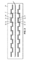
- the figure 2 reproduces the arrangement of the image sensors in the focal plane PF, which has been adopted for the WorldView-2 device.
- Two parallel rows of TDI detectors that are assigned to a broad spectral transmission window panchromatic imaging path, designated 1, are disposed in the PF focal plane of the apparatus, with line transfer directions that are parallel.
- Each TDI detector of the panchromatic channel can therefore be activated whatever the sub-swath scanning direction.
- Additional detectors 2a-2h are each formed of a line of photosensitive elements. They are also of the TDI type with two possible directions for line transfer. All the detectors 2a are associated with filters of narrow spectral width around a first color, those 2b with filters of spectral width still narrow around a second color, etc. for the detectors 2c-2h.
- the WorldView-2 imaging device thus combines obtaining a polychromatic image, that is to say, captured with a wider spectral width, with eight so-called chromatic channels, i.e. with spectral widths that are lower than that of the panchromatic pathway, and with a resolution of the ground which is fine, produced by the panchromatic way.
- the elementary pattern of the arrangement of the detectors is contained in the frame in dashed lines C. It is reproduced in the direction of the rows of photosensitive elements, to multiply the width of sub-swath. Line direction overlays for detectors of the same type, and their offsets in the perpendicular direction, make it possible to solve a congestion problem inside the focal plane PF, and to connect the segments of image lines which are seized by separate detectors.
- each of these is realized on a separate substrate, which is separate from that of the neighboring detectors 1 or 2a-2h.
- each detector 1 has two transfer registers and corresponding sets of outputs of the detection signals, which are located at the opposite ends of the columns of photosensitive elements of these sensors. detectors.
- the resulting congestion for the output connections of the detectors 1 of the panchromatic path then prevents to realize one of these detectors 1 on a substrate that would be common with some of the detectors 2a-2h chromatic channels.
- the WorldView-2 has a very large number of separate image detector substrates, which are particularly time-consuming in the focal plane at specific locations.
- the relative positions of some of these substrates may vary unintentionally, thereby producing misalignment between images that are captured by the detectors.
- the arrangement of separate detectors in different focal planes requires spatially dividing the imaging beam that is produced by the optics.
- Such a split-beam design is more complex because it requires the use of additional optical components, and the weight and bulk of the imaging apparatus are increased accordingly.
- the present invention aims to provide an imaging device that can be adapted simply for many space missions observation, especially for unidirectional or bidirectional push-broom scanning mode missions.
- Another object of the invention is to provide an imaging apparatus for which the arrangement of the image sensors in the focal plane is simplified and fast to achieve.
- Yet another goal is to provide an imaging apparatus whose design, weight and bulk are reduced.
- the main detector and each additional detector are made, for each detection unit separately from the other (other) set (s) of detection, on the same monobloc substrate ("single-piece substrate" in English) which is dedicated to this set of detection.
- the line of second photosensitive elements of each additional detector extends in the direction of lines on a second length which is between 0.9 and 1.1 times the first length, being shifted with respect to the lines of the main detector parallel to the column direction.
- the first and second lengths, respectively for the lines of the main detector and each additional detector, are equal within each detection assembly.
- the respective substrates of the two detection assemblies are both arranged in the same focal plane of the optics, and oriented so that their respective column directions are parallel to each other .
- they are arranged in the focal plane so that respective edge columns of the main detectors of these two detection assemblies, which are located on the edges of the main detectors oriented towards the same side of the focal plane, have an offset between them , measured in line direction, which is less than 5% of said first length.
- the realization on the same substrate of the main detector and at least one additional detector for each detection unit, is made possible by the selection of the unidirectional TDI type, that is to say to a single direction of line transfer. , for the main detector. In this way, it has only one transfer register, and only one corresponding set of output connections, so that it has a size that is compatible with the disposition of other detectors on the same substrate.
- each detection assembly consists of a separate and rigid detection block to be arranged in the focal plane.
- the main detector and the additional detector (s) of the same detection assembly are integral and have a positional relationship which is fixed during the manufacture of this detection assembly. This positional relationship is final, and is not subject to undergoing dispersions that would be introduced during the assembly in the focal plane of the optics, nor to undergo variations that would be caused later by dilations thermal or vibration.
- each detection assembly may have a peripheral shape which is simple, in particular rectangular or square, to constitute an image detection module.
- the apparatus comprises more than two detection assemblies, and at least two of them are juxtaposed elsewhere in the focal plane by being offset in the direction of lines, to increase the width of sub-mowed, the matching of the line lengths between the main detector and the additional detector (s) of each detection assembly simplifies the line termination overlaps to be provided between these detection assemblies. In particular, overlapping lengths that are equal can be provided for the main detectors and for the additional detectors.
- the second features of the invention indicate the modular organization of the detection assemblies within the focal plane.
- the two detection assemblies are arranged in the focal plane with respective column directions that are parallel.
- all detectors can be placed in the focal plane in a way that is simple and fast. Indeed, they are grouped on separate substrates, each carrying a main detector and at least one additional detector, so that the arrangement in the focal plane is reduced only to the placement and orientation of each substrate.
- the design of the imaging apparatus which can be in a single focal plane, is also simplified and reduces the number of optical components.
- specific components are not necessary to spatially divide the image forming light beam into several optical paths. The weight and bulk of the imaging apparatus can then be reduced for this reason.
- the offset between the respective edge columns of the main detectors of the two detection assemblies may be zero, so that these edge columns are aligned relative to each other in the column direction.
- the second filters may be identical for two additional detectors which belong respectively to one and the other of the two detection assemblies.
- the respective substrates of the two detection assemblies may be connected to provide additional detector redundancy.
- each detection assembly may comprise a plurality of additional detectors, all of which are made on the substrate of this assembly by being shifted in the direction of columns. All the additional detectors then each comprise at least one line of second photosensitive elements which are juxtaposed parallel to the line direction of the detection assembly, and this line also extends over a second length which is between 0.9 and 1.1 times the first length.
- the peripheral shape of each detection set with several additional detectors can be substantially rectangular, so that the arrangement of the detection sets in the focal plane remains simplified.
- the second filters of two additional detectors of this detection unit may be identical. These additional detectors can then be connected to provide additional detector redundancy.
- all the detection assemblies that are used in the same imaging apparatus according to the invention may be identical.
- Such similarity concerns the detection assemblies which group the detectors into elementary modules to be arranged in the focal plane. But it does not necessarily affect the filters that are associated respectively and individually to the detectors.
- the respective substrates of the two detection assemblies can be oriented further in the focal plane of so that the respective line transfer directions of the main detectors of these two detection assemblies are identical.
- This first orientation possibility can be adapted to produce stereoscopic imaging.
- the substrates of the two detection assemblies are arranged so that each of them is associated with a different line of sight through the optics of shooting.
- the respective substrates of the two detection assemblies can be arranged and connected to provide a main detector redundancy.
- a second possibility consists in orienting the respective substrates of the two detection assemblies so that the respective line transfer directions of their main detectors are opposite. This second possibility is compatible with bidirectional push-broom scanning mode.
- the filters which are respectively associated with the main detector and the additional detector (s) of each detection unit may be adapted so that the main detector constitutes a panchromatic imaging channel, and each additional detector is a chromatic imaging pathway, that is to say, whose spectral width is less than that of the panchromatic path.
- the spectral transmission window of each additional detector filter may be located within the spectral transmission window of the main detector filter of the same detection unit, being much narrower than the latter.
- each detection assembly comprises at least four additional detectors in addition to the main detector
- two identical sets of at least four second additional detector filters each may be respectively associated with a pair of detection assemblies arranged according to the invention.
- each set of second filters may comprise filters whose spectral transmission windows are separated. These second filters may be identical for the two detection sets.
- the first respective filters of the two detectors The main detection sets can also be identical, each with a spectral transmission window that extends between 450 nm and 900 nm.
- the first respective filters of the two main detectors of the detection assemblies may have respectively spectral transmission windows that are different.
- the imaging apparatus that is made in this way may be as described above.
- imaging apparatus may be used on board a satellite or an aircraft, for mission conditions and objectives which are identical to those described with reference to Figures 1a and 1 b.
- this imaging apparatus may be used on board a satellite or an aircraft, for mission conditions and objectives which are identical to those described with reference to Figures 1a and 1 b.
- those provisions which are most suitable for the unidirectional push-broom scanning figure 1a and those that are compatible with the bidirectional push-broom scanning mode of the figure 1 b.
- the imaging apparatus generally comprises a shooting optics 100, which forms an image of a scene in a focal plane PF. All Luminous flux detectors which are considered in the following are placed in this focal plane PF, that is to say they are arranged so that the light flux collecting surfaces are located in the plane PF. In a manner which is obvious to those skilled in the art, the apparatus further comprises all the necessary synchronization, control, read and record circuits which are necessary for the operation of the luminous flux detectors, although that these usual circuits are not described again.
- the luminous flux detectors are grouped into elementary modules 10 which are identical and separate, and these modules 10 are arranged in different ways in the focal plane PF.
- the modules 10 have been previously called detection sets in the general part of the description.
- the arrangement of the modules 10 in the focal plane PF is adapted according to the particularities of each observation mission, including the scanning mode, it being understood that the same model of elementary modules may be used with different arrangements.
- Such a modular arrangement within the focal plane constitutes an essential aspect of the present invention. This results in a significant cost reduction, thanks to the use of the same model of elementary modules for different observation missions.
- the alignment of the detectors relative to each other within the focal plane is also simplified, since it is reduced to the alignment of the elementary modules.
- each module 10 comprises a main detector and at least one additional detector.
- each module 10 comprises a main detector which is referenced 1 and four additional detectors which are referenced 2a-2d.
- the detector 1 is of unidirectional type. he comprises a square or rectangular matrix of photosensitive elements 11, with several lines L which are all parallel to the line direction DL. The photosensitive elements 11 are thus simultaneously aligned in columns which are all parallel to the direction of columns DC.
- the main detector 1 requires that the image which is formed by the photographic optics 100 on the photosensitive elements 11 moves parallel to the direction of columns DC, in a fixed direction which is called line transfer direction and noted TL.
- the main detector 1 determines, by its orientation in the focal plane PF, the scanning direction of each sub-swath that is captured by this detector 1.
- the main detector 1 of each module 10 may be of the time shift integration type, or TDI for "time-delayed integration" in English.
- the same main detector 1 can be used for the three examples of modules 10 of the Figures 3a to 3c .
- Each additional detector 2a-2d of the module 10 comprises at least one line of photosensitive elements 21, which extends parallel to the direction DL.
- the elements 21 are not necessarily identical to the elements 20.
- Each additional detector 2a-2d may be of the unidirectional or bidirectional type, but all the additional detectors of a same module 10 are preferably of the same of these two types.
- one of the additional detectors 2a-2d is of the bidirectional type, it is adapted to capture an image that moves in the focal plane PF parallel to the direction of columns DC, both in the line transfer direction TL of the detector main 1, itself monodirectional, only in the opposite direction.
- each module 10 is a one-piece component, rigid and separate from the others modules.
- the line direction DL is common to all the detectors 1 and 2a-2d of the module 10, and these detectors advantageously have line lengths that are identical and positions in the module that are shifted in the direction of DC columns. .
- all the detectors of the module 10 capture longitudinal portions of the same sub-swath which are identical, when scanning this sub-swath.
- the direction of this sweep is imposed by the main detector 1 and, when the additional detectors 2a-2d are also of the unidirectional type, they must be oriented in the module 10 to operate in the same line transfer direction TL as the main detector 1.
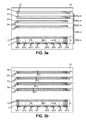
- the figure 3a shows the distribution of the light flux collecting surfaces of the photosensitive elements 11 and 21 for a first example of module 10.
- the additional detectors 2a-2d are of bidirectional type, each comprising a single line of photosensitive elements 21
- the additional detectors 2a-2d may each comprise several lines of elements 21 while remaining of the bidirectional type.
- the main detector 1, of the TDI type may comprise approximately 7000 photosensitive elements 11 per line L.
- the main detector 1 may have several read outputs which are denoted SP1 to SP8, and which are arranged in parallel for simultaneously read consecutive line segments in DL direction. The acquisition frequency of the lines by the entire module 10, which is most often determined by the detector 1, can thus be increased.
- Each secondary detector 2a-2d may have 3500 photosensitive elements 21 approximately.
- SX1 to SX4 denote the respective reading outputs of the detectors 2a-2d.
- the reading results of the elements 21 may be added for each separate pair of adjacent elements 21.
- the photosensitive elements 11 of the main detector 1 may advantageously have a pitch in the line direction DL, which is less than that of the photosensitive elements 21 of each additional detector 2a-2d.
- the module 10 is then adapted to produce images according to the "pan-sharpening" method, known to those skilled in the art.
- the additional detectors 2a-2d may be equipped with four color filters, and the main detector 1 may be equipped with a wide spectral transmission window filter, which may contain those of the detectors 2a-2d filters.
- a color filter is understood to mean a filter which is used for one of the detectors 2a-2d, and whose transmission spectral window is narrower than that of the filter of the main detector 1.
- the filter of the main detector 1 is said to be panchromatic, although it is possible that one of the chromatic spectral windows is not included in the panchromatic spectral window.
- the figure 3b corresponds to the figure 3a for a second example of module 10.
- the additional detectors 2a-2d are now also of the unidirectional type, with several lines of photosensitive elements 21 which are parallel and offset in the direction of columns DC.
- the main detector 1 and the additional detectors 2a-2d have respective line transfer directions TL which are all identical. This direction of line transfer is therefore imposed by all the detectors of the module 10, and no longer only by the main detector 1.
- the additional detectors 2a-2d can also be of the TDI type, for example each with three lines. 'TDI floors.
- figure 3c still corresponds to the figure 3a for a third example of module 10, again with additional sensors of the bidirectional type.
- Each additional detector 2a-2d is now a two-way TDI detector line transfer which are opposite.
- the charges which are accumulated by the elements 21 are transferred either in the line transfer direction TL which is defined for the main detector 1, or in the opposite direction, selectively according to the direction of movement of the image to be captured on the module 10.
- all the detectors of the same module 10 can be activated simultaneously when the image moves in the focal plane PF in the line transfer direction TL of the main detector 1.
- the additional detectors 2a-2d are bidirectional ( figures 3a and 3c ), they can also be activated while the direction of movement of the image in the focal plane PF is opposite the line transfer direction TL of the main detector 1. The latter is then inactivated.
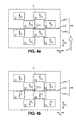
- Figures 4a and 4b each represent the focal plane PF, with the indication of its intersection with the optical axis A 100 of the optical image 100. Except in the case of stereoscopic imaging, it is assumed that the optical axis A 100 is confused with the line of sight of the imaging device.
- the focal plane PF is divided into two complementary half-planes PF1 and PF2, with a separation limit LS between them which is rectilinear and intersects the optical axis A 100 .
- All the modules 10 which are used for the same imaging apparatus are oriented in the focal plane PF to have the same direction of lines DL, and thus also the same direction of columns DC.
- the imaging apparatus is oriented on board the satellite S so that the direction of columns DC is parallel to the direction of movement V of the image in the PF focal plane.
- the orientation of each module is unequivocally characterized by the orientation of the line transfer direction TL of its main detector 1.
- all modules that are used for the same imaging apparatus are identical to each other.
- the broken line C indicates the arrangement pattern of the modules 10 in the focal plane PF.
- the two modules 10 which form this pattern are aligned with each other in the direction of columns DC.
- a transverse offset between these two modules 10 of the pattern can be implemented in the direction of lines DL, but remaining less than 5% of the length of the lines L of the main detectors 1.
- the pattern of the frame C can be repeated many times, for example four times, with successive offsets in the direction of lines DL, to increase the effective width of sub-mowed.
- the pattern can simultaneously be shifted in the direction of columns DC, to optimize a compromise between the space between modules 10 which are adjacent in the focal plane PF on the one hand, and the concentration of the detectors around the optical axis A 100 on the other hand, to reduce image distortions.
- two successive patterns in the direction of lines DL are advantageously shifted so that the lines of photosensitive elements of the modules have overlaps ends of lines.
- Such overlays which may be about one hundred photosensitive elements 11, make it easy to connect the image line segments that are gripped by separate modules.
- the modules 10 are all oriented so that their line transfer directions TL are identical, and this in the whole of the focal plane PF.
- all the detectors of the modules 10 can be used at the same time, since the displacement direction V of the image in the focal plane PF corresponds to the line transfer direction TL.
- two detectors that are identical within each pattern can be connected to provide redundancy.
- redundancy allows one of these detectors to be used in place of the other, in case the latter becomes defective.
- the two detectors concerned are equipped with identical filters. This is the case for the two main detectors 1 of modules 10 which are located at the same level in the DL line direction, or for two additional detectors of these modules.
- the additional detectors 2a-2d such redundancy can be obtained both between two additional detectors that belong to the same module 10, as for two additional detectors that belong to different modules 10 but located at the same level in the direction of DL lines.
- the layout of the figure 4a is suitable for unidirectional push-broom scanning mode, since the line transfer direction TL is unique.
- such an imaging device is not well suited to bidirectional push-broom scanning mode, since it would then be necessary to turn the device around the optical axis A 100 between two segments Longitudinal sub-furrows that are traversed in opposite directions.
- the layout of the figure 4a is also adapted to provide stereoscopic imaging of a scene that is contained in the object field, with two separate lines of sight that are implemented simultaneously.
- a stereoscopic observation is called "native stereo".
- those modules 10 which are contained in the half-plane PF1 are associated through the shooting optics 100 to a first line of sight
- those of the modules 10 which are contained in the half-plane PF2 are associated, also through the shooting optics 100, to a second line of sight which is different from the first but.
- Such native stereo imaging systems have already been shown elsewhere, so there is no need to describe them again here.
- the shooting optics 100 can be combined for this purpose with a beam division system and systems for determining the two separate lines of sight.
- the division of the image forming light beam is effected according to the distribution of the modules 10 between the two half-planes PF1 and PF2.
- the modules 10 of the same half-plane PF1 or PF2 are all oriented so that their line transfer directions TL are still identical within this half-plane. But this meaning is reversed between the two half-planes PF1 and PF2.
- the modules 10 of the half-plane PF1 on the one hand, and those of the half-plane PF2 on the other hand can be activated alternately, as a function of that of the half-planes for which the line transfer direction TL is identical to the direction of displacement of the image in the focal plane PF.
- Such an arrangement is particularly suitable for the bidirectional push-broom scanning mode. In this case, the image of each longitudinal sub-mowing segment is captured with the modules 10 from that of the two half-planes PF1 and PF2 for which the line transfer direction TL is identical to the direction of displacement of the image. in the focal plane PF.
- the first set of filters ( figure 5a ) is adapted to provide four color channels and one panchromatic channel.
- Each filter G1 to G4 is intended to be associated with an additional detector 2a-2d, and the filter PAN1 is intended to be associated with a main detector 1.
- the second set of filters ( figure 5b ) is adapted to provide eight color channels and two panchromatic channels.
- Each filter G5 to G12 is intended to be associated with an additional detector 2a-2d, and each filter PAN2 or PAN3 is intended to be associated with a main detector 1.
- the figure 6a shows two possible assignments of the filters of the first set, and an assignment of the filters of the second set, for the reason of arrangement of two modules 10 of the figure 4a (C frame in this figure). It is recalled that this pattern is better suited to unidirectional push-broom scanning mode, and possibly for native stereo imaging. Channel redundancies are obtained between the two main detectors 1 on the one hand, and for each pair of additional detectors 2a-2d which are provided with identical filters on the other hand.
- Each of the filter assignments that is given as an example is indicated by one of the columns on the right side of the figure 6a , and the filters which are assigned to the different detectors 1 and 2a-2d, are respectively registered at the same levels as the detectors concerned.
- the additional detector redundancies are performed between one and the other of the two modules 10.
- the additional detector redundancies are performed within each module 10.
- the third column shows the assignment of the ten filters of the second set, without redundancy.
- the figure 6b corresponds to the figure 6a for the reason of arrangement of two modules 10 of the figure 4b , better suited to bidirectional push-broom scanning.
- the assignment of the first set of filters, which is indicated in the first column, provides redundancy of additional detectors 2a-2d only if they are bidirectional. In this case, the redundancy is obtained between additional detectors 2a-2d which belong respectively to one and the other of the two modules, provided that they are provided with identical filters.
- the assignments of the second and third columns provide images for all color filters and for both scanning directions only if the additional sensors 2a-2d are still bidirectional.
- the assignment of the second column provides a redundancy of the additional detectors which are used for each direction of image displacement in the focal plane PF.
- the present invention may be reproduced by modifying certain aspects of the embodiments which have been described in detail, but still retain some of the advantages that have been cited.
- the distribution of the modules 10 in two halves of the focal plane PF with a line of separation LS which is rectilinear and which intersects the optical axis A 100 is not essential.
- the placement of the two modules 10 which belong to the same pattern of arrangement, at the same level along the line direction DL, is not essential either.
Landscapes
- Physics & Mathematics (AREA)
- Engineering & Computer Science (AREA)
- Multimedia (AREA)
- Spectroscopy & Molecular Physics (AREA)
- Signal Processing (AREA)
- General Physics & Mathematics (AREA)
- Optics & Photonics (AREA)
- Radar, Positioning & Navigation (AREA)
- Remote Sensing (AREA)
- Studio Devices (AREA)
Applications Claiming Priority (1)
| Application Number | Priority Date | Filing Date | Title |
|---|---|---|---|
| FR1203131A FR2998381B1 (fr) | 2012-11-21 | 2012-11-21 | Appareil d'imagerie a plusieurs ensembles de detection disposes dans un plan focal |
Publications (2)
| Publication Number | Publication Date |
|---|---|
| EP2735901A1 true EP2735901A1 (de) | 2014-05-28 |
| EP2735901B1 EP2735901B1 (de) | 2017-04-12 |
Family
ID=47989038
Family Applications (1)
| Application Number | Title | Priority Date | Filing Date |
|---|---|---|---|
| EP13193444.0A Active EP2735901B1 (de) | 2012-11-21 | 2013-11-19 | Bildgebungsgerät mit mehreren Erkennungseinheiten, die auf einer Brennebene angeordnet sind |
Country Status (3)
| Country | Link |
|---|---|
| US (1) | US9534893B2 (de) |
| EP (1) | EP2735901B1 (de) |
| FR (1) | FR2998381B1 (de) |
Cited By (1)
| Publication number | Priority date | Publication date | Assignee | Title |
|---|---|---|---|---|
| FR3033071A1 (fr) * | 2015-02-25 | 2016-08-26 | Centre Nat D'etudes Spatiales (Cnes) | Procede de determination d'un ensemble de mailles permettant d'imager une zone geographique |
Families Citing this family (7)
| Publication number | Priority date | Publication date | Assignee | Title |
|---|---|---|---|---|
| WO2014140189A2 (en) * | 2013-03-15 | 2014-09-18 | Forsvarets Forskningsinstitutt | Imaging unit |
| US10458904B2 (en) | 2015-09-28 | 2019-10-29 | Ball Aerospace & Technologies Corp. | Differential absorption lidar |
| DE102017208041A1 (de) * | 2017-05-12 | 2018-11-15 | Deutsches Zentrum für Luft- und Raumfahrt e.V. | TDI-Zeilendetektor |
| US10921245B2 (en) | 2018-06-08 | 2021-02-16 | Ball Aerospace & Technologies Corp. | Method and systems for remote emission detection and rate determination |
| ES2956789T3 (es) | 2019-01-03 | 2023-12-28 | OroraTech GmbH | Cámara térmica no refrigerada |
| DE102019211805B3 (de) * | 2019-08-06 | 2020-09-17 | Deutsches Zentrum für Luft- und Raumfahrt e.V. | Optisches System und TDI-Sensor |
| US11386649B2 (en) * | 2019-11-15 | 2022-07-12 | Maxar Intelligence Inc. | Automated concrete/asphalt detection based on sensor time delay |
Family Cites Families (1)
| Publication number | Priority date | Publication date | Assignee | Title |
|---|---|---|---|---|
| US4663656A (en) * | 1984-03-16 | 1987-05-05 | Rca Corporation | High-resolution CCD imagers using area-array CCD's for sensing spectral components of an optical line image |
-
2012
- 2012-11-21 FR FR1203131A patent/FR2998381B1/fr active Active
-
2013
- 2013-11-19 EP EP13193444.0A patent/EP2735901B1/de active Active
- 2013-11-21 US US14/086,006 patent/US9534893B2/en active Active
Non-Patent Citations (3)
| Title |
|---|
| CHRISTOPHE LATRY ET AL: "Staggered arrays for high resolution earth observing systems", PROCEEDINGS OF SPIE, vol. 7452, 21 August 2009 (2009-08-21), pages 74520O, XP055025448, ISSN: 0277-786X, DOI: 10.1117/12.825884 * |
| JAMES MILLER ; SUKHBIR KULLAR ; DAVID COCHRANE ; NIXON O ; ANDREY LOMAKO AND CEES DRAIJER: "Hyperspectral and multispectral sensors for remote sensing", SPIE, PO BOX 10 BELLINGHAM WA 98227-0010, USA, vol. 7857, 12 October 2010 (2010-10-12), pages 78570o-1 - 78570o-9, XP040545829, DOI: 10.1117/12.876474 * |
| RIENSTRA J ET AL: "Multispectral focal plane assembly for satellite remote sensing", AEROSPACE CONFERENCE, 1998 IEEE SNOWMASS AT ASPEN, CO, USA 21-28 MARCH 1998, NEW YORK, NY, USA,IEEE, US, vol. 5, 21 March 1998 (1998-03-21), pages 233 - 241, XP010287061, ISBN: 978-0-7803-4311-5, DOI: 10.1109/AERO.1998.685824 * |
Cited By (1)
| Publication number | Priority date | Publication date | Assignee | Title |
|---|---|---|---|---|
| FR3033071A1 (fr) * | 2015-02-25 | 2016-08-26 | Centre Nat D'etudes Spatiales (Cnes) | Procede de determination d'un ensemble de mailles permettant d'imager une zone geographique |
Also Published As
| Publication number | Publication date |
|---|---|
| US20140211006A1 (en) | 2014-07-31 |
| US9534893B2 (en) | 2017-01-03 |
| EP2735901B1 (de) | 2017-04-12 |
| FR2998381B1 (fr) | 2014-12-26 |
| FR2998381A1 (fr) | 2014-05-23 |
Similar Documents
| Publication | Publication Date | Title |
|---|---|---|
| EP2735901B1 (de) | Bildgebungsgerät mit mehreren Erkennungseinheiten, die auf einer Brennebene angeordnet sind | |
| EP2567537B1 (de) | Polychromatisches bildgebungsverfahren | |
| EP2515335B1 (de) | Bildgebender integrierter Schaltkreis, und Vorrichtung zur Erfassung von Stereobildern | |
| EP0738074B1 (de) | Detektionsverfahren mit verteilten Integrations- und Ausleseperioden für eine Abtastungskamera, und entsprechende Detektoranordnung | |
| FR3040798A1 (fr) | Camera plenoptique | |
| EP4078083B1 (de) | Verfahren zum erfassen von bildern eines terrestrischen bereichs unter verwendung eines raumfahrzeuges | |
| WO2012120214A2 (fr) | Systeme d'imagerie a haute resolution | |
| EP3494373B1 (de) | Spektrophotometrische vorrichtung mit einer vielzahl von spektralmessbändern | |
| EP2746830B1 (de) | Optische Feineinstellung eines Bilderfassungsgeräts | |
| EP4154046B1 (de) | Bildgebungsinstrument | |
| WO2011138542A1 (fr) | Procede d'imagerie | |
| FR2940720A1 (fr) | Dispositif de saisie d'images comprenant des moyens de correction de mise au point | |
| EP1829109A1 (de) | Bildsensor mit global getrennten farbzonen | |
| EP3217649B1 (de) | Bilderfassungssensor mit erweiterter zeitverzögerung und integration | |
| FR3024782A1 (fr) | Systeme et procede d'imagerie infrarouge | |
| EP3839814B1 (de) | Bordseitiges optisches beobachtungsinstrument mit variabler räumlicher und spektraler auflösung | |
| EP2093602A1 (de) | Bildgebungsvorrichtung mit mehreren Strahlablenkern | |
| EP4405648A1 (de) | Verfahren zur erfassung multispektraler bilder und panchromatischer miniaturbilder | |
| EP3190621A1 (de) | Hybrid-vorrichtung zur multispektralen erkennung anhand von monolithischen elementen | |
| WO2016146830A1 (fr) | Capteur d'images polarimétriques | |
| EP3069198B1 (de) | Kamera mit eine sehr hohe auflösung und eine sehr grosse bildgrösse | |
| EP3784998A1 (de) | Pupillenbildgebendes spektrometer | |
| WO2012076784A1 (fr) | Procede d'utilisation d'un capteur d'image |
Legal Events
| Date | Code | Title | Description |
|---|---|---|---|
| PUAI | Public reference made under article 153(3) epc to a published international application that has entered the european phase |
Free format text: ORIGINAL CODE: 0009012 |
|
| 17P | Request for examination filed |
Effective date: 20131119 |
|
| AK | Designated contracting states |
Kind code of ref document: A1 Designated state(s): AL AT BE BG CH CY CZ DE DK EE ES FI FR GB GR HR HU IE IS IT LI LT LU LV MC MK MT NL NO PL PT RO RS SE SI SK SM TR |
|
| AX | Request for extension of the european patent |
Extension state: BA ME |
|
| RAP1 | Party data changed (applicant data changed or rights of an application transferred) |
Owner name: AIRBUS DEFENCE AND SPACE SAS |
|
| R17P | Request for examination filed (corrected) |
Effective date: 20141106 |
|
| RBV | Designated contracting states (corrected) |
Designated state(s): AL AT BE BG CH CY CZ DE DK EE ES FI FR GB GR HR HU IE IS IT LI LT LU LV MC MK MT NL NO PL PT RO RS SE SI SK SM TR |
|
| RIC1 | Information provided on ipc code assigned before grant |
Ipc: H04N 3/14 20060101ALI20161128BHEP Ipc: G01J 3/28 20060101ALI20161128BHEP Ipc: G02B 27/10 20060101AFI20161128BHEP |
|
| GRAP | Despatch of communication of intention to grant a patent |
Free format text: ORIGINAL CODE: EPIDOSNIGR1 |
|
| STAA | Information on the status of an ep patent application or granted ep patent |
Free format text: STATUS: GRANT OF PATENT IS INTENDED |
|
| INTG | Intention to grant announced |
Effective date: 20170112 |
|
| GRAS | Grant fee paid |
Free format text: ORIGINAL CODE: EPIDOSNIGR3 |
|
| GRAA | (expected) grant |
Free format text: ORIGINAL CODE: 0009210 |
|
| STAA | Information on the status of an ep patent application or granted ep patent |
Free format text: STATUS: THE PATENT HAS BEEN GRANTED |
|
| AK | Designated contracting states |
Kind code of ref document: B1 Designated state(s): AL AT BE BG CH CY CZ DE DK EE ES FI FR GB GR HR HU IE IS IT LI LT LU LV MC MK MT NL NO PL PT RO RS SE SI SK SM TR |
|
| REG | Reference to a national code |
Ref country code: GB Ref legal event code: FG4D Free format text: NOT ENGLISH |
|
| REG | Reference to a national code |
Ref country code: CH Ref legal event code: EP |
|
| REG | Reference to a national code |
Ref country code: IE Ref legal event code: FG4D Free format text: LANGUAGE OF EP DOCUMENT: FRENCH |
|
| REG | Reference to a national code |
Ref country code: AT Ref legal event code: REF Ref document number: 884474 Country of ref document: AT Kind code of ref document: T Effective date: 20170515 |
|
| REG | Reference to a national code |
Ref country code: DE Ref legal event code: R096 Ref document number: 602013019687 Country of ref document: DE |
|
| REG | Reference to a national code |
Ref country code: NL Ref legal event code: MP Effective date: 20170412 |
|
| REG | Reference to a national code |
Ref country code: LT Ref legal event code: MG4D |
|
| REG | Reference to a national code |
Ref country code: AT Ref legal event code: MK05 Ref document number: 884474 Country of ref document: AT Kind code of ref document: T Effective date: 20170412 |
|
| PG25 | Lapsed in a contracting state [announced via postgrant information from national office to epo] |
Ref country code: NL Free format text: LAPSE BECAUSE OF FAILURE TO SUBMIT A TRANSLATION OF THE DESCRIPTION OR TO PAY THE FEE WITHIN THE PRESCRIBED TIME-LIMIT Effective date: 20170412 |
|
| PG25 | Lapsed in a contracting state [announced via postgrant information from national office to epo] |
Ref country code: LT Free format text: LAPSE BECAUSE OF FAILURE TO SUBMIT A TRANSLATION OF THE DESCRIPTION OR TO PAY THE FEE WITHIN THE PRESCRIBED TIME-LIMIT Effective date: 20170412 Ref country code: NO Free format text: LAPSE BECAUSE OF FAILURE TO SUBMIT A TRANSLATION OF THE DESCRIPTION OR TO PAY THE FEE WITHIN THE PRESCRIBED TIME-LIMIT Effective date: 20170712 Ref country code: FI Free format text: LAPSE BECAUSE OF FAILURE TO SUBMIT A TRANSLATION OF THE DESCRIPTION OR TO PAY THE FEE WITHIN THE PRESCRIBED TIME-LIMIT Effective date: 20170412 Ref country code: HR Free format text: LAPSE BECAUSE OF FAILURE TO SUBMIT A TRANSLATION OF THE DESCRIPTION OR TO PAY THE FEE WITHIN THE PRESCRIBED TIME-LIMIT Effective date: 20170412 Ref country code: ES Free format text: LAPSE BECAUSE OF FAILURE TO SUBMIT A TRANSLATION OF THE DESCRIPTION OR TO PAY THE FEE WITHIN THE PRESCRIBED TIME-LIMIT Effective date: 20170412 Ref country code: GR Free format text: LAPSE BECAUSE OF FAILURE TO SUBMIT A TRANSLATION OF THE DESCRIPTION OR TO PAY THE FEE WITHIN THE PRESCRIBED TIME-LIMIT Effective date: 20170713 Ref country code: AT Free format text: LAPSE BECAUSE OF FAILURE TO SUBMIT A TRANSLATION OF THE DESCRIPTION OR TO PAY THE FEE WITHIN THE PRESCRIBED TIME-LIMIT Effective date: 20170412 |
|
| REG | Reference to a national code |
Ref country code: FR Ref legal event code: PLFP Year of fee payment: 5 |
|
| PG25 | Lapsed in a contracting state [announced via postgrant information from national office to epo] |
Ref country code: IS Free format text: LAPSE BECAUSE OF FAILURE TO SUBMIT A TRANSLATION OF THE DESCRIPTION OR TO PAY THE FEE WITHIN THE PRESCRIBED TIME-LIMIT Effective date: 20170812 Ref country code: BG Free format text: LAPSE BECAUSE OF FAILURE TO SUBMIT A TRANSLATION OF THE DESCRIPTION OR TO PAY THE FEE WITHIN THE PRESCRIBED TIME-LIMIT Effective date: 20170712 Ref country code: RS Free format text: LAPSE BECAUSE OF FAILURE TO SUBMIT A TRANSLATION OF THE DESCRIPTION OR TO PAY THE FEE WITHIN THE PRESCRIBED TIME-LIMIT Effective date: 20170412 Ref country code: LV Free format text: LAPSE BECAUSE OF FAILURE TO SUBMIT A TRANSLATION OF THE DESCRIPTION OR TO PAY THE FEE WITHIN THE PRESCRIBED TIME-LIMIT Effective date: 20170412 Ref country code: SE Free format text: LAPSE BECAUSE OF FAILURE TO SUBMIT A TRANSLATION OF THE DESCRIPTION OR TO PAY THE FEE WITHIN THE PRESCRIBED TIME-LIMIT Effective date: 20170412 Ref country code: PL Free format text: LAPSE BECAUSE OF FAILURE TO SUBMIT A TRANSLATION OF THE DESCRIPTION OR TO PAY THE FEE WITHIN THE PRESCRIBED TIME-LIMIT Effective date: 20170412 |
|
| REG | Reference to a national code |
Ref country code: DE Ref legal event code: R097 Ref document number: 602013019687 Country of ref document: DE |
|
| PG25 | Lapsed in a contracting state [announced via postgrant information from national office to epo] |
Ref country code: DK Free format text: LAPSE BECAUSE OF FAILURE TO SUBMIT A TRANSLATION OF THE DESCRIPTION OR TO PAY THE FEE WITHIN THE PRESCRIBED TIME-LIMIT Effective date: 20170412 Ref country code: SK Free format text: LAPSE BECAUSE OF FAILURE TO SUBMIT A TRANSLATION OF THE DESCRIPTION OR TO PAY THE FEE WITHIN THE PRESCRIBED TIME-LIMIT Effective date: 20170412 Ref country code: EE Free format text: LAPSE BECAUSE OF FAILURE TO SUBMIT A TRANSLATION OF THE DESCRIPTION OR TO PAY THE FEE WITHIN THE PRESCRIBED TIME-LIMIT Effective date: 20170412 Ref country code: CZ Free format text: LAPSE BECAUSE OF FAILURE TO SUBMIT A TRANSLATION OF THE DESCRIPTION OR TO PAY THE FEE WITHIN THE PRESCRIBED TIME-LIMIT Effective date: 20170412 Ref country code: RO Free format text: LAPSE BECAUSE OF FAILURE TO SUBMIT A TRANSLATION OF THE DESCRIPTION OR TO PAY THE FEE WITHIN THE PRESCRIBED TIME-LIMIT Effective date: 20170412 |
|
| PLBE | No opposition filed within time limit |
Free format text: ORIGINAL CODE: 0009261 |
|
| STAA | Information on the status of an ep patent application or granted ep patent |
Free format text: STATUS: NO OPPOSITION FILED WITHIN TIME LIMIT |
|
| PG25 | Lapsed in a contracting state [announced via postgrant information from national office to epo] |
Ref country code: SM Free format text: LAPSE BECAUSE OF FAILURE TO SUBMIT A TRANSLATION OF THE DESCRIPTION OR TO PAY THE FEE WITHIN THE PRESCRIBED TIME-LIMIT Effective date: 20170412 |
|
| 26N | No opposition filed |
Effective date: 20180115 |
|
| PG25 | Lapsed in a contracting state [announced via postgrant information from national office to epo] |
Ref country code: SI Free format text: LAPSE BECAUSE OF FAILURE TO SUBMIT A TRANSLATION OF THE DESCRIPTION OR TO PAY THE FEE WITHIN THE PRESCRIBED TIME-LIMIT Effective date: 20170412 |
|
| PG25 | Lapsed in a contracting state [announced via postgrant information from national office to epo] |
Ref country code: MC Free format text: LAPSE BECAUSE OF FAILURE TO SUBMIT A TRANSLATION OF THE DESCRIPTION OR TO PAY THE FEE WITHIN THE PRESCRIBED TIME-LIMIT Effective date: 20170412 |
|
| PG25 | Lapsed in a contracting state [announced via postgrant information from national office to epo] |
Ref country code: CH Free format text: LAPSE BECAUSE OF NON-PAYMENT OF DUE FEES Effective date: 20171130 Ref country code: LI Free format text: LAPSE BECAUSE OF NON-PAYMENT OF DUE FEES Effective date: 20171130 |
|
| PG25 | Lapsed in a contracting state [announced via postgrant information from national office to epo] |
Ref country code: LU Free format text: LAPSE BECAUSE OF NON-PAYMENT OF DUE FEES Effective date: 20171119 |
|
| REG | Reference to a national code |
Ref country code: BE Ref legal event code: MM Effective date: 20171130 |
|
| REG | Reference to a national code |
Ref country code: IE Ref legal event code: MM4A |
|
| PG25 | Lapsed in a contracting state [announced via postgrant information from national office to epo] |
Ref country code: MT Free format text: LAPSE BECAUSE OF FAILURE TO SUBMIT A TRANSLATION OF THE DESCRIPTION OR TO PAY THE FEE WITHIN THE PRESCRIBED TIME-LIMIT Effective date: 20170412 |
|
| PG25 | Lapsed in a contracting state [announced via postgrant information from national office to epo] |
Ref country code: IE Free format text: LAPSE BECAUSE OF NON-PAYMENT OF DUE FEES Effective date: 20171119 |
|
| PG25 | Lapsed in a contracting state [announced via postgrant information from national office to epo] |
Ref country code: BE Free format text: LAPSE BECAUSE OF NON-PAYMENT OF DUE FEES Effective date: 20171130 |
|
| PG25 | Lapsed in a contracting state [announced via postgrant information from national office to epo] |
Ref country code: HU Free format text: LAPSE BECAUSE OF FAILURE TO SUBMIT A TRANSLATION OF THE DESCRIPTION OR TO PAY THE FEE WITHIN THE PRESCRIBED TIME-LIMIT; INVALID AB INITIO Effective date: 20131119 |
|
| PG25 | Lapsed in a contracting state [announced via postgrant information from national office to epo] |
Ref country code: CY Free format text: LAPSE BECAUSE OF NON-PAYMENT OF DUE FEES Effective date: 20170412 |
|
| PG25 | Lapsed in a contracting state [announced via postgrant information from national office to epo] |
Ref country code: MK Free format text: LAPSE BECAUSE OF FAILURE TO SUBMIT A TRANSLATION OF THE DESCRIPTION OR TO PAY THE FEE WITHIN THE PRESCRIBED TIME-LIMIT Effective date: 20170412 |
|
| PG25 | Lapsed in a contracting state [announced via postgrant information from national office to epo] |
Ref country code: TR Free format text: LAPSE BECAUSE OF FAILURE TO SUBMIT A TRANSLATION OF THE DESCRIPTION OR TO PAY THE FEE WITHIN THE PRESCRIBED TIME-LIMIT Effective date: 20170412 |
|
| PG25 | Lapsed in a contracting state [announced via postgrant information from national office to epo] |
Ref country code: PT Free format text: LAPSE BECAUSE OF FAILURE TO SUBMIT A TRANSLATION OF THE DESCRIPTION OR TO PAY THE FEE WITHIN THE PRESCRIBED TIME-LIMIT Effective date: 20170412 |
|
| PG25 | Lapsed in a contracting state [announced via postgrant information from national office to epo] |
Ref country code: AL Free format text: LAPSE BECAUSE OF FAILURE TO SUBMIT A TRANSLATION OF THE DESCRIPTION OR TO PAY THE FEE WITHIN THE PRESCRIBED TIME-LIMIT Effective date: 20170412 |
|
| PGFP | Annual fee paid to national office [announced via postgrant information from national office to epo] |
Ref country code: GB Payment date: 20231123 Year of fee payment: 11 |
|
| PGFP | Annual fee paid to national office [announced via postgrant information from national office to epo] |
Ref country code: IT Payment date: 20231124 Year of fee payment: 11 Ref country code: FR Payment date: 20231120 Year of fee payment: 11 Ref country code: DE Payment date: 20231121 Year of fee payment: 11 |