EP2735882A2 - MRI system and method of diagnosing the same - Google Patents
MRI system and method of diagnosing the same Download PDFInfo
- Publication number
- EP2735882A2 EP2735882A2 EP13190987.1A EP13190987A EP2735882A2 EP 2735882 A2 EP2735882 A2 EP 2735882A2 EP 13190987 A EP13190987 A EP 13190987A EP 2735882 A2 EP2735882 A2 EP 2735882A2
- Authority
- EP
- European Patent Office
- Prior art keywords
- gradient
- coil
- pulse
- mri system
- modified
- Prior art date
- Legal status (The legal status is an assumption and is not a legal conclusion. Google has not performed a legal analysis and makes no representation as to the accuracy of the status listed.)
- Withdrawn
Links
Images


Classifications
-
- A—HUMAN NECESSITIES
- A61—MEDICAL OR VETERINARY SCIENCE; HYGIENE
- A61B—DIAGNOSIS; SURGERY; IDENTIFICATION
- A61B5/00—Measuring for diagnostic purposes; Identification of persons
- A61B5/05—Detecting, measuring or recording for diagnosis by means of electric currents or magnetic fields; Measuring using microwaves or radio waves
- A61B5/055—Detecting, measuring or recording for diagnosis by means of electric currents or magnetic fields; Measuring using microwaves or radio waves involving electronic [EMR] or nuclear [NMR] magnetic resonance, e.g. magnetic resonance imaging
-
- G—PHYSICS
- G01—MEASURING; TESTING
- G01R—MEASURING ELECTRIC VARIABLES; MEASURING MAGNETIC VARIABLES
- G01R33/00—Arrangements or instruments for measuring magnetic variables
- G01R33/20—Arrangements or instruments for measuring magnetic variables involving magnetic resonance
- G01R33/44—Arrangements or instruments for measuring magnetic variables involving magnetic resonance using nuclear magnetic resonance [NMR]
- G01R33/48—NMR imaging systems
- G01R33/54—Signal processing systems, e.g. using pulse sequences ; Generation or control of pulse sequences; Operator console
- G01R33/56—Image enhancement or correction, e.g. subtraction or averaging techniques, e.g. improvement of signal-to-noise ratio and resolution
- G01R33/565—Correction of image distortions, e.g. due to magnetic field inhomogeneities
- G01R33/56572—Correction of image distortions, e.g. due to magnetic field inhomogeneities caused by a distortion of a gradient magnetic field, e.g. non-linearity of a gradient magnetic field
-
- G—PHYSICS
- G01—MEASURING; TESTING
- G01R—MEASURING ELECTRIC VARIABLES; MEASURING MAGNETIC VARIABLES
- G01R33/00—Arrangements or instruments for measuring magnetic variables
- G01R33/20—Arrangements or instruments for measuring magnetic variables involving magnetic resonance
- G01R33/44—Arrangements or instruments for measuring magnetic variables involving magnetic resonance using nuclear magnetic resonance [NMR]
- G01R33/48—NMR imaging systems
- G01R33/54—Signal processing systems, e.g. using pulse sequences ; Generation or control of pulse sequences; Operator console
- G01R33/56—Image enhancement or correction, e.g. subtraction or averaging techniques, e.g. improvement of signal-to-noise ratio and resolution
- G01R33/565—Correction of image distortions, e.g. due to magnetic field inhomogeneities
-
- G—PHYSICS
- G01—MEASURING; TESTING
- G01R—MEASURING ELECTRIC VARIABLES; MEASURING MAGNETIC VARIABLES
- G01R33/00—Arrangements or instruments for measuring magnetic variables
- G01R33/20—Arrangements or instruments for measuring magnetic variables involving magnetic resonance
- G01R33/44—Arrangements or instruments for measuring magnetic variables involving magnetic resonance using nuclear magnetic resonance [NMR]
- G01R33/48—NMR imaging systems
- G01R33/58—Calibration of imaging systems, e.g. using test probes, Phantoms; Calibration objects or fiducial markers such as active or passive RF coils surrounding an MR active material
-
- G—PHYSICS
- G01—MEASURING; TESTING
- G01R—MEASURING ELECTRIC VARIABLES; MEASURING MAGNETIC VARIABLES
- G01R33/00—Arrangements or instruments for measuring magnetic variables
- G01R33/20—Arrangements or instruments for measuring magnetic variables involving magnetic resonance
- G01R33/44—Arrangements or instruments for measuring magnetic variables involving magnetic resonance using nuclear magnetic resonance [NMR]
- G01R33/48—NMR imaging systems
- G01R33/54—Signal processing systems, e.g. using pulse sequences ; Generation or control of pulse sequences; Operator console
- G01R33/56—Image enhancement or correction, e.g. subtraction or averaging techniques, e.g. improvement of signal-to-noise ratio and resolution
- G01R33/565—Correction of image distortions, e.g. due to magnetic field inhomogeneities
- G01R33/56518—Correction of image distortions, e.g. due to magnetic field inhomogeneities due to eddy currents, e.g. caused by switching of the gradient magnetic field
Definitions
- the present invention relates to a magnetic resonance imaging (MRI) system and, in particular, to a method of diagnosing the MRI system.
- MRI magnetic resonance imaging
- a magnetic resonance imaging (MRI) system generates an image by using information obtained from resonance that occurs after exposing an atomic nucleus to a magnetic field.
- the resonance of an atomic nucleus refers to a phenomenon whereby, when a particular high frequency wave is incident on an atomic nucleus in a state of being magnetized by an external magnetic field, the atomic nucleus in a low energy state absorbs a high frequency wave energy and thus, is excited to a high energy state.
- the atomic nucleus has a resonant frequency that differs according to the type of atomic nucleus. The resonance is affected by the strength of an external magnetic field.
- An MRI system includes a magnet for forming a main magnetic field in a scanning space, a radio frequency (RF) coil for generating an RF signal in the scanning space, and a gradient coil for forming a gradient magnetic field to select a scanning area of a target object in the scanning space.
- RF radio frequency
- a gradient coil for forming a gradient magnetic field to select a scanning area of a target object in the scanning space.
- a pulse sequence designed for scanning a target object is applied to the RF coil and the gradient coil, and an echo signal of the RF signal generated from the scanning space is obtained.
- the signals output by the RF coil and the gradient coil have errors due to many factors. The errors in an output signal deteriorate a signal to noise ratio (SNR) of an MR image.
- an MR image may include artifacts.
- the present invention provides a magnetic resonance imaging (MRI) system that may simply and accurately measure an error of a gradient coil and compensate an output thereof, and a method of diagnosing the MRI system.
- MRI magnetic resonance imaging
- a method of diagnosing a magnetic resonance imaging (MRI) system includes forming a gradient magnetic field in a scanning space where a target object is positioned by generating a plurality of modified gradient pulses based on a reference gradient pulse and applying one of the plurality of modified gradient pulses to one of an x-axis coil, a y-axis coil, and a z-axis coil included in a gradient coil, applying a radio frequency (RF) pulse from an RF coil to the target object in the scanning space where the gradient magnetic field corresponding to each of the plurality of modified gradient pulses is formed, and receiving a plurality of RF signals that are generated from the target object and correspond to the plurality of modified gradient pulses, and compensating an output of the gradient coil based on the plurality of received RF signals.
- RF radio frequency
- the compensating of the output may include determining a tuning value with respect to the reference gradient pulse by considering the plurality of received RF signals, and adjusting a pulse sequence applied to the gradient coil based on the tuning value.
- the compensating of the output may include selecting an optimal modified gradient pulse for optimizing the RF signal based on the plurality of received RF signals and adjusting a pulse sequence applied to the gradient coil based on a difference between the optimal modified gradient pulse and the reference gradient pulse.
- the pulse sequence may include at least one of a spin echo sequence, a turbo spin echo sequence, an inversion recovery sequence, a gradient echo sequence, and a field echo sequence.
- the forming of the gradient magnetic field may include generating the plurality of modified gradient pulses by modifying at least one of the height, width, and phase of the reference gradient pulse.
- the output of the gradient coil may be compensated based on a difference between the reference gradient pulse and a modified gradient pulse corresponding to one of the plurality of received RF signals that has the largest amplitude.
- the reference gradient pulse may include a first pulse having a positive (+) value and a second pulse having a negative (-) value and the first and second pulses have the same amplitude.
- the RF signal may include a pulse having a phase of 90° and a pulse having a phase of 180°, and the reference gradient pulse comprises a first pulse having a phase that is earlier than 180° and a second pulse having a phase that is later than 180°, with the first and second pulses having the same amplitude.
- the method may further include determining whether the MRI system is stable by using the reference gradient pulse, wherein only when the MRI system is determined to be stable is the forming of the gradient magnetic field, the receiving of the plurality of RF signals, and the compensating of the output of the gradient coil performed.
- the determining of whether the MRI system is stable may include forming a gradient magnetic field in the scanning space by applying the reference gradient pulse to at least one of the x-axis coil, the y-axis coil, and the z-axis coil, repeating multiple times applying of an RF pulse from the RF coil to the target object in the scanning space where the gradient magnetic field is formed and receiving of an RF signal generated from the target object in the scanning space where the gradient magnetic field is formed, the RF signal being received by a receiving coil, and determining that the MRI system is stable when a change in at least one of an amplitude and a phase of the received RF signals is within a predetermined range.
- the method may further include remotely receiving a user input, and performing the MRI system diagnosis method based on the user input.
- a method of diagnosing a magnetic resonance imaging (MRI) system includes forming a gradient magnetic field in a scanning space where a target object is positioned by applying a predetermined reference gradient pulse to at least one of an x-axis coil, a y-axis coil, and a z-axis coil included in a gradient coil, repeating multiple times applying of an RF pulse from the RF coil to the target object in the scanning space where the gradient magnetic field is formed and receiving of an RF signal generated from the target object, the RF signal being received by a receiving coil, and determining whether the MRI system is stable based on a change in at least one of an amplitude and a phase of the received RF signals.
- MRI magnetic resonance imaging
- a magnetic resonance imaging (MRI) system includes a magnet for forming a main magnetic field in a scanning space where a target object is positioned, a radio frequency (RF) coil for generating an RF signal in the scanning space, a gradient coil driving unit for forming a gradient magnetic field in the scanning space by applying one of a plurality of modified gradient pulses generated based on a predetermined reference gradient pulse to one of an x-axis coil, a y-axis coil, and a z-axis coil included in a gradient coil, a receiving coil for receiving a plurality of RF signals that are generated from the target object in the scanning space where a gradient magnetic field is formed and corresponds to the plurality of modified gradient pulses, and a control unit for controlling the magnet, the RF coil, the gradient coil, the gradient coil driving unit, and the receiving coil, wherein the control unit compensates an output of the gradient coil based on the plurality of received RF signals.
- RF radio frequency
- a magnetic resonance imaging (MRI) system includes a magnet for forming a main magnetic field in a scanning space where a target object is positioned, a radio frequency (RF) coil for generating an RF pulse in the scanning space, a gradient coil driving unit for forming a gradient magnetic field in the scanning space by applying a predetermined gradient pulse to at least one of an x-axis coil, a y-axis coil, and a z-axis coil included in a gradient coil, a receiving coil repeatedly for receiving multiple times an RF signal that is generated from the target object in the scanning space where a gradient magnetic field is formed, a stability check unit for determining whether the MRI system is stable based on a change in at least one of an amplitude and a phase of each of the received RF signals, and a control unit for controlling the magnet, the RF coil, the gradient coil, the receiving coil, the gradient coil driving unit, and the stability check unit.
- RF radio frequency
- portion may signify a unit to process at least one function or operation and the unit may be embodied by hardware, software executed by hardware, or a combination of hardware and software.
- a computer software command to embody the present invention hardware, software executed by hardware, or a combination of hardware and software may be used instead of a programmed processor/controller. Accordingly, the present invention is not limited by a specific combination of hardware and software.
- a "target object” may be one of various internal organs or particular parts of a human body or an animal.
- the target object may be a phantom that signifies a material having a density of a living creature and a volume and other characteristics close to the physical characteristics such as atomic numbers of elements and molecules in portions of the living creature, such as tissues.
- the phantom may be a water phantom having a spherical shape and properties similar to portions of a human body.
- a "scanning space” signifies a space in which a target object is positioned or retained, or a space in which a medical imaging apparatus may apply or receive a predetermined signal to obtain an image signal generated from the target object.
- the inner space of the gantry may be a scanning space of the MRI system.
- a "user” may be a medical expert such as a medical doctor, a nurse, a clinical pathologist, a medical image expert, or a technologist who repairs medical equipment, but the present invention is not limited thereto.
- a "pulse sequence” signifies a sequence of signals that are repeatedly applied in an MRI system.
- the pulse sequence may include time parameters of a radio frequency (RF) pulse, for example, repetition time (TR) and time to echo (TE).
- RF radio frequency
- TR repetition time
- TE time to echo
- a "pulse sequence schematic” refers to an order of events happening in an MRI system.
- a pulse sequence schematic illustrates RF pulses, a gradient magnetic field, and an echo RF signal in a passage of time.
- a “gradient pulse” signifies signals applied to a gradient coil so that a gradient coil may generate a perturbation in a magnetic field in a scanning space.
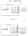
- FIG. 1 is a block diagram schematically illustrating a general MRI system of the prior art.
- a target object 105 undergoes an examination in a cylindrical gantry and/or on a table in a shielded room which is shielded against an external radio frequency (RF) signal.
- RF radio frequency
- a main magnetic field is formed in the gantry by a magnet 110 and a gradient magnetic field is formed by a gradient coil 140.
- atomic nuclei in the target object 105 precess about a direction of the magnetic field.
- a frequency such as a resonant frequency of this precession is proportional to the strength of an external magnetic field according to the Lamor equation.
- the atomic nuclei When an RF pulse of the same frequency as the resonant frequency is transmitted toward the atomic nuclei precessing at the resonant frequency and the transmission of the RF pulse is stopped, the atomic nuclei externally emit the absorbed RF pulses to be detected by the MRI system 100, and then the MRI system 100 obtains an MR image by using the RF pulse emitted from the atomic nuclei.
- An RF coil 130 applies an RF pulse of a resonant frequency to the target object 105 to obtain an MR image.
- a receiving coil 120 receives an echo signal generated in a particular portion of a patient and transfers a received echo signal to a central control apparatus 150 located in a space separated from the shielded room. The echo signal is finally converted to an MR image through a signal processing process.
- the gradient coil 140 includes x-axis, y-axis, and z-axis gradient coils.
- An MRI system forms a gradient magnetic field by applying an appropriate gradient pulse according to the position and angle of a section of the target object 105 to be scanned.
- the gradient coil 140 may be classified into a slice selection gradient (GS) coil, a frequency encoding gradient (GF) coil, and a phase encoding gradient (GP) according to a function of the gradient magnetic field.
- GS slice selection gradient
- GF frequency encoding gradient
- GP phase encoding gradient
- a slice selection gradient magnetic field may be formed by an x-axis gradient coil, or alternatively by a y-axis gradient coil or a z-axis gradient coil in some cases.
- the MRI system 100 applies a pulse sequence, designed to scan the target object 105, to the RF coil 130 and the gradient coil 140, and obtains an echo signal of an RF signal generated in a scanning space where the target object 105 is positioned.
- the signals output from the RF coil 130 and the gradient coil 140 may have errors due to many factors.
- a method of compensating for an error by tuning the MRI system 100 to each of designed pulse sequences has been used. Thus, as the number of pulse sequences having errors to be compensated for increases, an excessive tuning time is needed.
- FIGS. 2A and 2B are block diagrams schematically illustrating an MRI system 200 according to an exemplary embodiment of the present invention.
- the MRI system 200 according to the exemplary embodiment includes a magnet 210, a receiving coil 220, an RF coil 230, and a gradient coil 240 in a shielded room which shields the target object from an external RF signal.
- the gradient coil 240 includes x-axis, y-axis, and z-axis gradient coils.
- the MRI system 200 includes a gradient coil driving unit 260and a control unit 250 outside the shielded room.
- the gradient coil 240 may further include a stability check unit 255 and an input unit 265 outside the shielded room.
- the gradient coil driving unit 260 may be provided in the shielded room.
- the input unit 265 may be used as a receiving unit for receiving inputs, for example, remotely from a user, as shown in FIG. 7 .
- the magnet 210 generates or forms a main magnetic field in the scanning space.
- the gradient coil 240 forms a gradient magnetic field in the scanning space.
- the RF coil 230 applies an RF pulse to the target object 105 that is positioned in the scanning space where the gradient magnetic field is formed.
- the receiving coil 220 receives an RF signal generated from the target object 105 to which the RF pulse is applied.
- the gradient coil driving unit 260 forms a gradient magnetic field in the scanning space by applying one of a plurality of modified gradient pulses generated based on a predetermined reference gradient pulse to one of an x-axis coil, a y-axis coil, and a z-axis coil of the gradient coil 240.
- the receiving coil 220 receives a plurality of RF signals generated from the target object 105 in the scanning space where a gradient magnetic field corresponding to the modified gradient pulses is generated or formed.
- the control unit 250 controls overall operations of the MRI system 200.
- the control unit 250 may control the magnet 210, the RF coil 230, the gradient coil 240, the receiving coil 220, and the gradient coil driving unit 260 overall by executing programs stored in a memory included in or connected to the control unit 250.
- the control unit 250 may obtain an RF signal from the receiving coil 220.
- the control unit 250 may compensate an output of the gradient coil 240 based on an obtained RF signal, and may generate control signals for controlling the gradient coil driving unit 260 to generate and transmit a modified gradient pulse signal which is used to control the gradient coil 240 to generate a modified gradient magnetic field, as described herein in the present invention.
- control unit 250 may obtain an RF signal from the receiving coil 220 and transmit an obtained RF signal to a stability check unit 255, shown in FIG. 2B , which is connected to the control unit 250.
- the operation of the stability check unit 255 to determine whether the MRI system 200 is stable is described below with reference to FIGS. 5A-5E and 6 .
- FIG. 3 is a flowchart for illustrating a method of diagnosing the MRI system 200, including compensating an output of the gradient coil 240, according to the exemplary embodiment of the present invention.
- the MRI system diagnosis method may include operations processed in the MRI system 200 of FIGS. 2A and 2B .
- the above descriptions of the MRI system 200 of FIGS. 2A and 2B may be applied to the MRI system diagnosis method of FIG. 3 .
- the MRI system 200 applies the modified gradient pulses, generated based on a predetermined reference gradient pulse, to one of the x-axis coil, y-axis coil, and z-axis coil, and thus a gradient magnetic field is formed in the scanning space where the target object 105 is positioned.
- the reference gradient pulse is a signal applied to the gradient coil 240 to induce an intentional change in a magnetic field in the scanning space and is previously determined to have a constant form regardless of which one of the x-axis coil, y-axis coil, and z-axis coil that the reference gradient pulse is applied to.
- the reference gradient pulse used for diagnosis of the MRI system 200 may include a first pulse having a positive (+) value, and a second pulse having a negative (-) value.
- the first and second pulses may be bipolar pulses having the same amplitude.
- the reference gradient pulse may be a unipolar pulse including a first pulse having a phase that is earlier than 180° and a second pulse having a phase that is later than 180° and having the same amplitude as that of the first pulse, but the present invention is not limited thereto.
- the MRI system 200 may generate the "modified gradient pulses" by modifying the amplitude of the reference gradient pulse.
- the modified gradient pulse may include the same pulse as the reference gradient pulse or a pulse having the same shape as that of the reference gradient pulse but having an amplitude larger or smaller than that of the reference gradient pulse.
- the pulses may be compared according to the intensity of an electric current applied to the gradient coil associated with each pulse.
- the MRI system 200 may generate the modified gradient pulses by modifying at least one of the height, width, and phase of the reference gradient pulse.
- step S320 the MRI system 200 applies an RF pulse to the target object 105 in the scanning space where a gradient magnetic field is formed by the gradient coil 240 in step S310.
- the MRI system 200 transmits an RF pulse to the target object 105 and then stops the transmission of the RF pulse, the target object 105 having absorbed the RF pulse generates an RF signal to be emitted externally.
- the receiving coil 220 receives a plurality of RF signals corresponding to the respective modified gradient pulses applied to the gradient coil 240 in step S310.
- the MRI system 200 forms a gradient magnetic field in the scanning space by applying a predetermined modified gradient pulse, and receives an RF signal corresponding to the modified gradient pulse by applying an RF pulse from the RF coil 230 toward the scanning space where the gradient magnetic field is formed.
- the MRI system 200 changes the gradient magnetic field formed in the scanning space by modifying the applied gradient pulse and repeats the operations of applying an RF pulse toward the scanning space where the gradient magnetic field is changed and receiving an RF signal.
- the received RF signals may be stored in an internal storage device or an external storage device of the MRI system 200, such as in memory of the control unit 250, or external memory connected to the control unit 250.
- step S330 the control unit 250 of the MRI system 200 compensates an output of the gradient coil 240 based on the received RF signals, for example, the control unit 250 generates control signals representing the compensated output.
- step S340 in response to the control signals from the control unit 250, the gradient coil driving unit 260 generates and transmits a modified gradient pulse signal to the gradient coil 240, which in turn generates a modified gradient magnetic field in the MRI system 200 in step S350. Step S330 will be described in detail below with reference to FIGS. 4A, 4B, 4C, and 4D .
- FIGS. 4A, 4B, 4C, and 4D are views for illustrating a method of compensating for an error included in an output of the gradient coil 240, according to the exemplary embodiment of the present invention.
- the reference gradient pulse used in the present invention may be, for example, a bipolar pulse 402 or a unipolar pulse 401.
- the MRI system 200 may generate a plurality of modified gradient pulses based on the reference gradient pulses 401 and 402.
- modified gradient pulses represented by the circled "A” are generated by changing the amplitudes of the reference gradient pulses 401 and 402, and the modified gradient pulse, represented by the circled "A", is applied to one of the x-axis coil, the y-axis coil, and the z-axis coil included in the gradient coil 240 so that a gradient magnetic field may be formed in the scanning space.
- the MRI system 200 repeats the processes of applying an RF pulse to the target object 105 in the scanning space where a gradient magnetic field corresponding to the modified gradient pulse is formed, and of receiving a plurality of RF signals 403.
- the MRI system 200 obtains tuning information from the received RF signals 403 and compensates for an error included in an output of the gradient coil 240, that is, the outputted gradient magnetic field.
- the MRI system 200 may alter the reference gradient pulse to receive a predetermined RF signal and use a tuning value obtained by altering the reference gradient pulse as the tuning information for tuning the MRI system 200.
- the MRI system 200 may detect an optimal modified gradient pulse for optimizing a received echo signal, that is, an RF signal that is generated from the target object 105 and received from the receiving coil 220.
- the MRI system 200 may detect, as an optimal modified gradient pulse, a modified gradient pulse when one of the received RF signals, which is located closest to a predetermined phase or has the largest amplitude, is received.
- the MRI system 200 may compensate for an output of the gradient coil 240 based on a difference between the optimal modified gradient pulse and the reference gradient pulse.
- the MRI system 200 may adjust a pulse sequence applied to the gradient coil 240 to compensate the output of the gradient coil 240.
- a method of adjusting a pulse sequence may include a method of changing a pulse sequence value stored in a database included in the MRI system 200, with the database stored in a memory of the control unit 250, and storing the changed pulse sequence value instead of the pulse sequence and a method of adjusting a stored pulse sequence value during scanning of or obtaining a medical image and applying the adjusted pulse sequence value to the gradient coil 240.
- a pulse sequence may include at least one of a spin echo sequence, a turbo spin echo sequence, an inversion recovery sequence, a gradient echo sequence, and a field echo sequence, or other pulse sequences known in the art.
- FIG. 4B illustrates data obtained by receiving RF signals corresponding to, for example, 256 modified gradient pulses having different amplitudes.
- a change in a pulse applied to one of the x-axis coil, the y-axis coil, and the z-axis coil included in the gradient coil 240 may affect the amplitude of an RF signal.
- the coil that affects the amplitude of an RF signal may be a GS coil or a GP coil.
- FIG. 4B is a graph showing an RF signal received after a modified gradient pulse is applied to the GS or GP coil of the gradient coil 240 in the MRI system 200. In the graph of FIG.
- the x-axis represents the number of received RF signals
- the y-axis illustrates the amplitude of a received RF signal, for example, in Joules (J).
- the MRI system 200 may regard a modified gradient pulse corresponding to one of the received RF signals having the largest amplitude as an optimal modified gradient pulse, and obtains a difference between the optimal gradient pulse and the reference gradient pulse as tuning information.
- a difference between a modified gradient pulse corresponding to the 135 th RF signal and the reference gradient pulse may be used as tuning information to compensate for an error included in an output of the gradient coil 240.As illustrated in FIGS.
- the modified gradient pulses used in the present invention may be generated by changing at least one of the height, width, and phase of each of the reference gradient pulses 401 and 402 shown in FIG. 4A , with the modified gradient pulse 401 shown in FIG. 4C , and the modified gradient pulse 402 shown in FIG. 4D .
- the MRI system 200 may generate the modified gradient pulses 401, 402 by changing at least one of a height A, a ramp time R, a delay time D, and a phase of the reference gradient pulse.
- the MRI system 200 repeats the processes of applying an RF pulse to the target object 105 in the scanning space where a gradient magnetic field corresponding to a generated modified gradient pulse is formed and receiving the RF signals 403 shown in FIG. 4A .
- the MRI system 200 may detect an optimal modified gradient pulse that optimizes an RF signal from the received RF signals 403.
- the MRI system 200 may compensate for an error by applying the tuning information obtained by using the reference gradient pulse to both various pulse sequences and various image processing options; for example, to adjust a pulse sequence using the tuning information or tuning value for applying of the adjusted sequence to the gradient coil 240.
- MR angiography based image improvement is possible and flow artifacts may be improved by performing error correction using flow compensation technology.
- accuracy of a velocity encoding gradient magnetic field may be improved in phase contrast MR angiography.
- the MRI system 200 according to the exemplary embodiment does not need separate tuning of the pulse sequences designed for scanning and obtaining a medical image and thus maintenance and repair of the MRI system 200 may be performed quickly.
- the MRI system 200 may determine whether the MRI system 200 is stable by using the reference gradient pulse used for tuning.
- the MRI system 200 may be configured to compensate an output of the gradient coil 240 only when the MRI system 200 is determined to be stable.
- the reference gradient pulse is applied to at least one of the x-axis coil, the y-axis coil, and the z-axis coil included in the gradient coil 240 to form a gradient magnetic field in the scanning space.
- the RF coil 230 applies an RF pulse to the target object 105 in the scanning space where the gradient magnetic field is formed.
- the receiving coil 220 receives an RF signal generated from the target object 105. Accordingly, whether the MRI system 200 is stable may be determined based on at least one of the amplitude and phase of the received RF signal.
- the MRI system 200 may be determined to be stable.
- the reference RF signal may be an RF signal that is expected to be received by the receiving coil 220.
- the expected RF signal may be determined by calculating the gradient magnetic field formed in the scanning space and an RF pulse applied to the target object 105.
- the predetermined margin of error may be a range that is experimentally set during manufacturing of the MRI system 200 or by the user while using of the MRI system 200.
- the MRI system 200 may calculate stability of the MRI system 200 based on at least one of the amplitude and phase of obtained RF signals by processing a plurality of RF signal data obtained through a repeated operation. For example, a process of obtaining an RF signal from the target object 105, by applying a predetermined gradient pulse to the target object 105 in the scanning space where the gradient magnetic field is formed, is repeated, for example, 200 times or more. When a change in the amplitude of the received RF signals obtained by the repeated operation is within a predetermined range, the MRI system 200 may be determined to be stable, which is a predetermined criteria for determining the stability of the MRI system 200.
- the MRI system 200 may be determined to be unstable.
- a user may determine the reason for the instability and have the MRI system 200 repaired.
- the MRI system 200 may automatically compensate an output of the gradient coil 240 as described above with reference to FIGS. 2-4D , for example, under the control of the control unit 250 and without the need for inputs from the user.
- the MRI system 200 may apply an RF pulse to the target object 105 without forming a gradient magnetic field in the scanning space by not applying a pulse to the gradient coil 240.
- the MRI system 200 may receive a gradient-off RF signal from the target object 105 in the scanning space where no gradient magnetic field is formed and use a received gradient-off RF signal to determine whether the MRI system 200 is stable.
- FIGS. 5A, 5B, 5C, 5D, and 5E are views of pulse sequences used to determine whether the MRI system 200 is stable in the MRI system diagnosis method of FIG. 3 .
- "X", “Y”, and “Z” indicate signals applied to the x-axis coil, the y-axis coil, and the z-axis coil, respectively, and "signal” refers to a signal received by the receiving coil 220.
- whether the MRI system 200 is stable may be determined based on an RF signal 501 obtained by applying an RF pulse only to the RF coil 230 when the gradient coil 240 is turned off.
- the MRI system 200 may be determined to be stable when the amplitude or phase of the obtained RF signal 501 is within a predetermined margin of error compared to a reference RF signal or when a change in the amplitude or phase of the obtained RF signal 501 after repeating the above process multiple times is within a predetermined range.
- the MRI system 200 is determined to be stable by using a pulse sequence in FIG.
- whether the MRI system 200 is stable may be determined based on RF signals 502, 503, and 504 obtained by applying a predetermined reference gradient pulse 510 to one of the x-axis coil, the y-axis coil, and the z-axis coil included in the gradient coil 240.
- the MRI system 200 may be determined to be stable when the amplitude or phase of each of the obtained RF signals 502, 503, and 504 is within a predetermined margin of error compared to a reference RF signal or when a change in the amplitude or phase of each of the obtained RF signals 502, 503, and 504 after repeating the above process multiple times is within a predetermined range.
- the MRI system 200 is determined to be stable by using pulse sequences in FIGS. 5B, 5C, and 5D , it may be seen that the operation of a part related to the driving of, for example, the gradient coil 240 in the MRI system 200 is stable.
- whether the MRI system 200 is stable may be determined based on an RF signal 505 obtained by applying the predetermined reference gradient pulse 510 to all of the x-axis coil, the y-axis coil, and the z-axis coil included in the gradient coil 240.
- the MRI system 200 may be determined to be stable when the amplitude or phase of each of the obtained RF signals 505 from each iteration of the above process is within a predetermined margin of error compared to a reference RF signal or when a change in the amplitude or phase of each of the obtained RF signals 505 from each iteration of the above process is within a predetermined range.
- the MRI system 200 is determined to be stable by using the pulse sequences in FIG. 5E , it may be seen that the operation of a part related to the driving of, for example, the gradient coil 240 in the MRI system 200 is stable.
- the MRI system 200 may measure, evaluate, and diagnose the stability of the whole system by using at least one reference gradient pulse.
- a stability check process may be simplified and a checking time, that is, the time to diagnose the functionality of the MRI system 200 may be reduced.
- FIG. 6 is a flowchart for illustrating a method of determining whether the MRI system 200 is stable in the MRI system diagnosis method of FIG. 3 .
- the stability check of the MRI system 200 by using any of the pulse sequences shown in FIGS. 5A-5E may be performed in the order shown in FIG. 6 .
- a stability check of the RF coil 230 and the receiving coil 220 may be performed.
- the pulse sequence of FIG. 5A may be used for the stability check.
- the MRI system 200 may determine in step S620 whether parts related to the driving of the RF coil 230 and the receiving coil 220 are stable, based on an RF signal generated from the target object 105 in the scanning space where no gradient magnetic field is formed.
- the MRI system 200 may output information in step S625 indicating that the RF coil 230 and the receiving coil 220 need to be repaired.
- the information may be output, for example, from a display of the MRI system 200 as shown in FIG. 7 or by other known output devices such as a printer, which may be connected to the control unit 250.
- a user may, for example, modify software in the MRI system 200 or replace parts corresponding to the RF coil 230 and the receiving coil 220.
- step S625 the method loops back to perform steps S610-S620.
- a stability check of the gradient coil 240 may be performed in step S630.
- the pulse sequences in FIGS. 5B, 5C, 5D, and 5E may be used for the stability check.
- the MRI system 200 may determine in step S640 whether the part related to the driving of the gradient coil 240 is stable, based on an RF signal generated from the target object 105 in the scanning space that is formed by applying the predetermined reference gradient pulse 510 to one or all of the x-axis coil, the y-axis coil, and the z-axis coil.
- the MRI system 200 may output information in step S645, for example, from a display of the MRI system 200 as shown in FIG. 7 or by other known output devices such as a printer, indicating that the gradient coil 240 needs to be repaired, and the method loops back to perform steps S630-S640.
- a user may, for example, modify software in the MRI system 200 or replace a part corresponding to the gradient coil 240.
- the user may determine a reason for the instability of the MRI system 200 according to whether a received RF signal is stable for each case of applying the reference gradient pulse 510 to the x-axis coil, the y-axis coil, the z-axis coil, and all of the x-axis coil, the y-axis coil, and the z-axis coil, as shown in FIGS. 5B-5E , respectively.
- the MRI system 200 may perform data processing of the amplitude and phase of an RF signal obtained from the receiving coil 220 and present a total evaluation report to the user, for example, through the display in FIG. 7 or by other known output devices such as a printer, for diagnosing the MRI system 200.
- a user may recognize problems of the MRI system 200 from the total evaluation report.
- the user may diagnose the MRI system 200 and recognize problems by comparing the amplitude and phase of an RF signal obtained from the receiving coil 220 with preset values.
- the "preset values" may be simulated values or calculated values of an RF signal that is expected to be obtained when a problem occurs in each part of the MRI system 200.
- step S640 when the parts related to the driving of the RF coil 230, the receiving coil 220, and the gradient coil 240 are all determined to be stable, the MRI system 200 is determined in step S640 to be stable and the stability check is terminated in step S650.
- the stability of the MRI system 200 may be checked more quickly and simply by using a predetermined test gradient pulse.
- the MRI system 200 may be repaired.
- the MRI system 200 may be used to check the stability of the MRI system 200 used to compensate for an error of an output of the gradient coil 240.
- the MRI system 200 according to the exemplary embodiment may use the gradient pulse used to compensate for an error of an output of the gradient coil 240 to check the stability of the MRI system 200.
- the MRI system 200 may compensate the output of the gradient coil 240 by using the reference gradient pulse used for the stability check only when the MRI system 200 is determined to be stable. In compensating for an error included in the output of the gradient coil 240, when the MRI system 200 is stable, the error may be accurately measured and compensated for.
- the MRI system 200 according to the exemplary embodiment may perform the operation of determining whether the MRI system 200 is stable and the operation of compensating of the output of the gradient coil 240 as one operation.
- the process is simplified and thus a possibility of a user making an error in the diagnosis of the MRI system is greatly reduced.
- accuracy in a check result and an error compensation result is greatly improved.
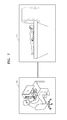
- FIG. 7 schematically illustrates an MRI system 720 remotely receiving a user input according to the exemplary embodiment of the present invention.
- the method of diagnosing an MRI system according to the exemplary embodiment may be performed based on a user input that is remotely received.
- the process of diagnosing and repairing the MRI system 720 may be greatly simplified.
- the state of the MRI system 720 may be measured, adjusted, evaluated, and diagnosed by a user 710 using a terminal or workstation, which may include a display or other output devices, as well as the input unit 265 shown in FIG.
- the input unit 265 and/or the entire terminal or workstation operate at least as a receiving unit to receive inputs from the user, for example, remotely from the MRI system 720. Since these processes are performed remotely through a network, the user 710 does not need to directly visit a place where the MRI system 720 is located, for diagnosis and repair of the MRI system 720, and time and costs may also be saved.
- the MRI system 720 may further include a receiving unit for remotely receiving a user input through the input unit 265.
- the user 710 may store a diagnosis result and an error compensation record of the MRI system 720, for example, in a memory of the terminal or workstation.
- the user 710 may quickly recognize the reasons for the problem by referring to the stored diagnosis result and error compensation record.
- the tuning process of an MRI system is more simple and accurate.
- a user remotely located from the MRI system may analyze a problem and repair the MRI system without having to visit a site where the MRI system is located.
- the above-described apparatus and methods according to the present invention can be implemented in hardware or firmware, or as software or computer code, or combinations thereof.
- the software or computer code can also be stored in a non-transitory recording medium such as a CD ROM, a RAM, a ROM whether erasable or rewritable or not, a floppy disk, CDs, DVDs, memory chips, a hard disk, a magnetic storage media, an optical recording media, or a magneto-optical disk or computer code downloaded over a network originally stored on a remote recording medium, a computer readable recording medium, or a non-transitory machine readable medium and to be stored on a local recording medium, so that the methods described herein can be rendered in such software, computer code, software modules, software objects, instructions, applications, applets, apps, etc.
- the computer, the processor, microprocessor controller or the programmable hardware include volatile and/or non-volatile storage and memory components, e.g., RAM, ROM, Flash, etc. that may store or receive software or computer code that when accessed and executed by the computer, processor or hardware implement the processing methods described herein.
- volatile and/or non-volatile storage and memory components e.g., RAM, ROM, Flash, etc.
- the execution of the code transforms the general purpose computer into a special purpose computer for executing the processing shown herein.
- the program may be electronically transferred through any medium such as communication signals transmitted by wire/wireless connections, and their equivalents.
- the programs and computer readable recording medium can also be distributed in network-coupled computer systems so that the computer readable code is stored and executed in a distributed fashion.
Abstract
Description
- This application claims, pursuant to 35 U.S.C. 119(a), prior to and the benefit of the earlier filing date of Korean Patent Application No.
10-2012-0134867, filed on November 26, 2012 - The present invention relates to a magnetic resonance imaging (MRI) system and, in particular, to a method of diagnosing the MRI system.
- A magnetic resonance imaging (MRI) system generates an image by using information obtained from resonance that occurs after exposing an atomic nucleus to a magnetic field. The resonance of an atomic nucleus refers to a phenomenon whereby, when a particular high frequency wave is incident on an atomic nucleus in a state of being magnetized by an external magnetic field, the atomic nucleus in a low energy state absorbs a high frequency wave energy and thus, is excited to a high energy state. The atomic nucleus has a resonant frequency that differs according to the type of atomic nucleus. The resonance is affected by the strength of an external magnetic field. There are numerous atomic nuclei in a human body and a hydrogen atomic nucleus is generally used for MRI.
- An MRI system includes a magnet for forming a main magnetic field in a scanning space, a radio frequency (RF) coil for generating an RF signal in the scanning space, and a gradient coil for forming a gradient magnetic field to select a scanning area of a target object in the scanning space. In the MRI system, a pulse sequence designed for scanning a target object is applied to the RF coil and the gradient coil, and an echo signal of the RF signal generated from the scanning space is obtained. The signals output by the RF coil and the gradient coil have errors due to many factors. The errors in an output signal deteriorate a signal to noise ratio (SNR) of an MR image. Also, an MR image may include artifacts.
- The present invention provides a magnetic resonance imaging (MRI) system that may simply and accurately measure an error of a gradient coil and compensate an output thereof, and a method of diagnosing the MRI system.
- According to an aspect of the present invention, a method of diagnosing a magnetic resonance imaging (MRI) system includes forming a gradient magnetic field in a scanning space where a target object is positioned by generating a plurality of modified gradient pulses based on a reference gradient pulse and applying one of the plurality of modified gradient pulses to one of an x-axis coil, a y-axis coil, and a z-axis coil included in a gradient coil, applying a radio frequency (RF) pulse from an RF coil to the target object in the scanning space where the gradient magnetic field corresponding to each of the plurality of modified gradient pulses is formed, and receiving a plurality of RF signals that are generated from the target object and correspond to the plurality of modified gradient pulses, and compensating an output of the gradient coil based on the plurality of received RF signals.
- The compensating of the output may include determining a tuning value with respect to the reference gradient pulse by considering the plurality of received RF signals, and adjusting a pulse sequence applied to the gradient coil based on the tuning value. The compensating of the output may include selecting an optimal modified gradient pulse for optimizing the RF signal based on the plurality of received RF signals and adjusting a pulse sequence applied to the gradient coil based on a difference between the optimal modified gradient pulse and the reference gradient pulse. The pulse sequence may include at least one of a spin echo sequence, a turbo spin echo sequence, an inversion recovery sequence, a gradient echo sequence, and a field echo sequence.
- The forming of the gradient magnetic field may include generating the plurality of modified gradient pulses by modifying at least one of the height, width, and phase of the reference gradient pulse. In the compensating of the output, the output of the gradient coil may be compensated based on a difference between the reference gradient pulse and a modified gradient pulse corresponding to one of the plurality of received RF signals that has the largest amplitude.
- The reference gradient pulse may include a first pulse having a positive (+) value and a second pulse having a negative (-) value and the first and second pulses have the same amplitude. The RF signal may include a pulse having a phase of 90° and a pulse having a phase of 180°, and the reference gradient pulse comprises a first pulse having a phase that is earlier than 180° and a second pulse having a phase that is later than 180°, with the first and second pulses having the same amplitude.
- The method may further include determining whether the MRI system is stable by using the reference gradient pulse, wherein only when the MRI system is determined to be stable is the forming of the gradient magnetic field, the receiving of the plurality of RF signals, and the compensating of the output of the gradient coil performed. The determining of whether the MRI system is stable may include forming a gradient magnetic field in the scanning space by applying the reference gradient pulse to at least one of the x-axis coil, the y-axis coil, and the z-axis coil, repeating multiple times applying of an RF pulse from the RF coil to the target object in the scanning space where the gradient magnetic field is formed and receiving of an RF signal generated from the target object in the scanning space where the gradient magnetic field is formed, the RF signal being received by a receiving coil, and determining that the MRI system is stable when a change in at least one of an amplitude and a phase of the received RF signals is within a predetermined range.
- The method may further include remotely receiving a user input, and performing the MRI system diagnosis method based on the user input.
- According to another aspect of the present invention, a method of diagnosing a magnetic resonance imaging (MRI) system includes forming a gradient magnetic field in a scanning space where a target object is positioned by applying a predetermined reference gradient pulse to at least one of an x-axis coil, a y-axis coil, and a z-axis coil included in a gradient coil, repeating multiple times applying of an RF pulse from the RF coil to the target object in the scanning space where the gradient magnetic field is formed and receiving of an RF signal generated from the target object, the RF signal being received by a receiving coil, and determining whether the MRI system is stable based on a change in at least one of an amplitude and a phase of the received RF signals.
- According to another aspect of the present invention, a magnetic resonance imaging (MRI) system includes a magnet for forming a main magnetic field in a scanning space where a target object is positioned, a radio frequency (RF) coil for generating an RF signal in the scanning space, a gradient coil driving unit for forming a gradient magnetic field in the scanning space by applying one of a plurality of modified gradient pulses generated based on a predetermined reference gradient pulse to one of an x-axis coil, a y-axis coil, and a z-axis coil included in a gradient coil, a receiving coil for receiving a plurality of RF signals that are generated from the target object in the scanning space where a gradient magnetic field is formed and corresponds to the plurality of modified gradient pulses, and a control unit for controlling the magnet, the RF coil, the gradient coil, the gradient coil driving unit, and the receiving coil, wherein the control unit compensates an output of the gradient coil based on the plurality of received RF signals.
- According to another aspect of the present invention, a magnetic resonance imaging (MRI) system includes a magnet for forming a main magnetic field in a scanning space where a target object is positioned, a radio frequency (RF) coil for generating an RF pulse in the scanning space, a gradient coil driving unit for forming a gradient magnetic field in the scanning space by applying a predetermined gradient pulse to at least one of an x-axis coil, a y-axis coil, and a z-axis coil included in a gradient coil, a receiving coil repeatedly for receiving multiple times an RF signal that is generated from the target object in the scanning space where a gradient magnetic field is formed, a stability check unit for determining whether the MRI system is stable based on a change in at least one of an amplitude and a phase of each of the received RF signals, and a control unit for controlling the magnet, the RF coil, the gradient coil, the receiving coil, the gradient coil driving unit, and the stability check unit.
- The above and other features and advantages of the present invention will become more apparent by describing in detail exemplary embodiments thereof with reference to the attached drawings in which:
-
FIG. 1 is a block diagram schematically illustrating a general magnetic resonance imaging (MRI) system in the prior art; -
FIGS. 2A and2B are block diagrams schematically illustrating an MRI system according to an exemplary embodiment of the present invention; -
FIG. 3 is a flowchart for illustrating a method of diagnosing an MRI system according to the exemplary embodiment of the present invention; -
FIGS. 4A, 4B, 4C, and 4D are views for illustrating a method of compensating an output of a gradient coil, according to the exemplary embodiment of the present invention; -
FIGS. 5A, 5B, 5C, 5D, and 5E are views of pulse sequences used to determine whether an MRI system is stable in the MRI system diagnosis method ofFIG. 3 ; -
FIG. 6 is a flowchart for illustrating a method of determining whether an MRI system is stable in the MRI system diagnosis method ofFIG. 3 ; and -
FIG. 7 schematically illustrates an MRI system remotely receiving a user input according to the exemplary embodiment of the present invention. - The attached drawings for illustrating exemplary embodiments of the present invention are referred to in order to gain a sufficient understanding of the present invention, the merits thereof, and the objectives accomplished by the implementation of the present invention. Hereinafter, the present invention will be described in detail by illustrating exemplary embodiments of the invention with reference to the attached drawings. Like reference numerals in the drawings refer to like elements. The present invention may, however, be embodied in many different forms and should not be construed as limited to the exemplary embodiments set forth herein. In addition, terms described herein, which are defined with reference to the functions of the present invention, may be implemented differently depending on a user or operator's intention and practice. Therefore, the terms should be understood on the basis of the disclosure throughout the specification. The principles and features of this invention may be employed in varied and numerous embodiments without departing from the scope of the invention.
- Furthermore, although the drawings represent exemplary embodiments of the invention, the drawings are not necessarily to scale and certain features may be exaggerated or omitted in order to more clearly illustrate and explain the present invention.
- Expressions such as "at least one of', when preceding a list of elements, modify the entire list of elements and do not modify the individual elements of the list.
- The present invention will now be described more fully with reference to the accompanying drawings, in which exemplary embodiments of the invention are shown. In the following description, detailed descriptions about well-known functions or structures, which may obscure the main concept of the present invention, will be omitted herein.
- When a part may "include" a certain constituent element, unless specified otherwise, it may not be construed to exclude another constituent element but may be construed to further include other constituent elements. The terms such as "portion", "unit", "module", and "block" stated in the specification may signify a unit to process at least one function or operation and the unit may be embodied by hardware, software executed by hardware, or a combination of hardware and software. Also, as a computer software command to embody the present invention, hardware, software executed by hardware, or a combination of hardware and software may be used instead of a programmed processor/controller. Accordingly, the present invention is not limited by a specific combination of hardware and software.
- Throughout the present specification, a "target object" may be one of various internal organs or particular parts of a human body or an animal. Also, the target object may be a phantom that signifies a material having a density of a living creature and a volume and other characteristics close to the physical characteristics such as atomic numbers of elements and molecules in portions of the living creature, such as tissues. For example, the phantom may be a water phantom having a spherical shape and properties similar to portions of a human body.
- Throughout the present specification, a "scanning space" signifies a space in which a target object is positioned or retained, or a space in which a medical imaging apparatus may apply or receive a predetermined signal to obtain an image signal generated from the target object. For example, for a magnetic resonance imaging (MRI) system including a cylindrical gantry, the inner space of the gantry may be a scanning space of the MRI system. Throughout the present specification, a "user" may be a medical expert such as a medical doctor, a nurse, a clinical pathologist, a medical image expert, or a technologist who repairs medical equipment, but the present invention is not limited thereto.
- Throughout the present specification, a "pulse sequence" signifies a sequence of signals that are repeatedly applied in an MRI system. The pulse sequence may include time parameters of a radio frequency (RF) pulse, for example, repetition time (TR) and time to echo (TE). Throughout the present specification, a "pulse sequence schematic" refers to an order of events happening in an MRI system. In other words, a pulse sequence schematic illustrates RF pulses, a gradient magnetic field, and an echo RF signal in a passage of time. Throughout the present specification, a "gradient pulse" signifies signals applied to a gradient coil so that a gradient coil may generate a perturbation in a magnetic field in a scanning space.
-
FIG. 1 is a block diagram schematically illustrating a general MRI system of the prior art. - A
target object 105 undergoes an examination in a cylindrical gantry and/or on a table in a shielded room which is shielded against an external radio frequency (RF) signal. A main magnetic field is formed in the gantry by amagnet 110 and a gradient magnetic field is formed by agradient coil 140. When a magnetic field is formed outside thetarget object 105, atomic nuclei in thetarget object 105 precess about a direction of the magnetic field. A frequency such as a resonant frequency of this precession is proportional to the strength of an external magnetic field according to the Lamor equation. When an RF pulse of the same frequency as the resonant frequency is transmitted toward the atomic nuclei precessing at the resonant frequency and the transmission of the RF pulse is stopped, the atomic nuclei externally emit the absorbed RF pulses to be detected by theMRI system 100, and then theMRI system 100 obtains an MR image by using the RF pulse emitted from the atomic nuclei. - An
RF coil 130 applies an RF pulse of a resonant frequency to thetarget object 105 to obtain an MR image. A receivingcoil 120 receives an echo signal generated in a particular portion of a patient and transfers a received echo signal to acentral control apparatus 150 located in a space separated from the shielded room. The echo signal is finally converted to an MR image through a signal processing process. - The
gradient coil 140 includes x-axis, y-axis, and z-axis gradient coils. An MRI system forms a gradient magnetic field by applying an appropriate gradient pulse according to the position and angle of a section of thetarget object 105 to be scanned. Thegradient coil 140 may be classified into a slice selection gradient (GS) coil, a frequency encoding gradient (GF) coil, and a phase encoding gradient (GP) according to a function of the gradient magnetic field. For example, a slice selection gradient magnetic field may be formed by an x-axis gradient coil, or alternatively by a y-axis gradient coil or a z-axis gradient coil in some cases. - The
MRI system 100 applies a pulse sequence, designed to scan thetarget object 105, to theRF coil 130 and thegradient coil 140, and obtains an echo signal of an RF signal generated in a scanning space where thetarget object 105 is positioned. The signals output from theRF coil 130 and thegradient coil 140 may have errors due to many factors. In the prior art, a method of compensating for an error by tuning theMRI system 100 to each of designed pulse sequences has been used. Thus, as the number of pulse sequences having errors to be compensated for increases, an excessive tuning time is needed. -
FIGS. 2A and2B are block diagrams schematically illustrating anMRI system 200 according to an exemplary embodiment of the present invention. Referring toFIGS. 2A and2B , theMRI system 200 according to the exemplary embodiment includes amagnet 210, a receivingcoil 220, anRF coil 230, and agradient coil 240 in a shielded room which shields the target object from an external RF signal. Thegradient coil 240 includes x-axis, y-axis, and z-axis gradient coils. Also, theMRI system 200 includes a gradient coil driving unit 260and acontrol unit 250 outside the shielded room. Thegradient coil 240 may further include astability check unit 255 and aninput unit 265 outside the shielded room. Alternatively, at least one of the gradientcoil driving unit 260, thestability check unit 255, theinput unit 265, and thecontrol unit 250 may be provided in the shielded room. Theinput unit 265 may be used as a receiving unit for receiving inputs, for example, remotely from a user, as shown inFIG. 7 . - The
magnet 210 generates or forms a main magnetic field in the scanning space. Thegradient coil 240 forms a gradient magnetic field in the scanning space. TheRF coil 230 applies an RF pulse to thetarget object 105 that is positioned in the scanning space where the gradient magnetic field is formed. The receivingcoil 220 receives an RF signal generated from thetarget object 105 to which the RF pulse is applied. - The gradient
coil driving unit 260 forms a gradient magnetic field in the scanning space by applying one of a plurality of modified gradient pulses generated based on a predetermined reference gradient pulse to one of an x-axis coil, a y-axis coil, and a z-axis coil of thegradient coil 240. The receivingcoil 220 receives a plurality of RF signals generated from thetarget object 105 in the scanning space where a gradient magnetic field corresponding to the modified gradient pulses is generated or formed. - In conjunction with inputs from a user of the
MRI system 200, with the inputs received through theinput unit 265 connected to thecontrol unit 250, thecontrol unit 250 controls overall operations of theMRI system 200. For example, thecontrol unit 250 may control themagnet 210, theRF coil 230, thegradient coil 240, the receivingcoil 220, and the gradientcoil driving unit 260 overall by executing programs stored in a memory included in or connected to thecontrol unit 250. Also, thecontrol unit 250 may obtain an RF signal from the receivingcoil 220. Thecontrol unit 250 may compensate an output of thegradient coil 240 based on an obtained RF signal, and may generate control signals for controlling the gradientcoil driving unit 260 to generate and transmit a modified gradient pulse signal which is used to control thegradient coil 240 to generate a modified gradient magnetic field, as described herein in the present invention. - According to the exemplary embodiment, the
control unit 250 may obtain an RF signal from the receivingcoil 220 and transmit an obtained RF signal to astability check unit 255, shown inFIG. 2B , which is connected to thecontrol unit 250. The operation of thestability check unit 255 to determine whether theMRI system 200 is stable is described below with reference toFIGS. 5A-5E and6 . -
FIG. 3 is a flowchart for illustrating a method of diagnosing theMRI system 200, including compensating an output of thegradient coil 240, according to the exemplary embodiment of the present invention. Referring toFIG. 3 , the MRI system diagnosis method may include operations processed in theMRI system 200 ofFIGS. 2A and2B . The above descriptions of theMRI system 200 ofFIGS. 2A and2B may be applied to the MRI system diagnosis method ofFIG. 3 . - In step S310, the
MRI system 200 applies the modified gradient pulses, generated based on a predetermined reference gradient pulse, to one of the x-axis coil, y-axis coil, and z-axis coil, and thus a gradient magnetic field is formed in the scanning space where thetarget object 105 is positioned. The reference gradient pulse is a signal applied to thegradient coil 240 to induce an intentional change in a magnetic field in the scanning space and is previously determined to have a constant form regardless of which one of the x-axis coil, y-axis coil, and z-axis coil that the reference gradient pulse is applied to. - According to the exemplary embodiment, the reference gradient pulse used for diagnosis of the
MRI system 200 may include a first pulse having a positive (+) value, and a second pulse having a negative (-) value. The first and second pulses may be bipolar pulses having the same amplitude. Also, when an RF pulse applied to theRF coil 230 in a pulse sequence includes a pulse having a phase of 90° and a pulse having a phase of 180°, the reference gradient pulse may be a unipolar pulse including a first pulse having a phase that is earlier than 180° and a second pulse having a phase that is later than 180° and having the same amplitude as that of the first pulse, but the present invention is not limited thereto. - Also, according to the exemplary embodiment, the
MRI system 200 may generate the "modified gradient pulses" by modifying the amplitude of the reference gradient pulse. Thus, the modified gradient pulse may include the same pulse as the reference gradient pulse or a pulse having the same shape as that of the reference gradient pulse but having an amplitude larger or smaller than that of the reference gradient pulse. Alternatively, the pulses may be compared according to the intensity of an electric current applied to the gradient coil associated with each pulse. - In addition, according to the exemplary embodiment, the
MRI system 200 may generate the modified gradient pulses by modifying at least one of the height, width, and phase of the reference gradient pulse. - In step S320, the
MRI system 200 applies an RF pulse to thetarget object 105 in the scanning space where a gradient magnetic field is formed by thegradient coil 240 in step S310. When theMRI system 200 transmits an RF pulse to thetarget object 105 and then stops the transmission of the RF pulse, thetarget object 105 having absorbed the RF pulse generates an RF signal to be emitted externally. The receivingcoil 220 receives a plurality of RF signals corresponding to the respective modified gradient pulses applied to thegradient coil 240 in step S310. - In other words, the
MRI system 200 forms a gradient magnetic field in the scanning space by applying a predetermined modified gradient pulse, and receives an RF signal corresponding to the modified gradient pulse by applying an RF pulse from theRF coil 230 toward the scanning space where the gradient magnetic field is formed. To obtain a plurality of RF signals, theMRI system 200 changes the gradient magnetic field formed in the scanning space by modifying the applied gradient pulse and repeats the operations of applying an RF pulse toward the scanning space where the gradient magnetic field is changed and receiving an RF signal. The received RF signals may be stored in an internal storage device or an external storage device of theMRI system 200, such as in memory of thecontrol unit 250, or external memory connected to thecontrol unit 250. In step S330, thecontrol unit 250 of theMRI system 200 compensates an output of thegradient coil 240 based on the received RF signals, for example, thecontrol unit 250 generates control signals representing the compensated output. In step S340, in response to the control signals from thecontrol unit 250, the gradientcoil driving unit 260 generates and transmits a modified gradient pulse signal to thegradient coil 240, which in turn generates a modified gradient magnetic field in theMRI system 200 in step S350. Step S330 will be described in detail below with reference toFIGS. 4A, 4B, 4C, and 4D . -
FIGS. 4A, 4B, 4C, and 4D are views for illustrating a method of compensating for an error included in an output of thegradient coil 240, according to the exemplary embodiment of the present invention. - Referring to
FIG. 4A , the reference gradient pulse used in the present invention may be, for example, abipolar pulse 402 or aunipolar pulse 401. TheMRI system 200 according to the exemplary embodiment may generate a plurality of modified gradient pulses based on thereference gradient pulses FIG. 4A , modified gradient pulses, represented by the circled "A", are generated by changing the amplitudes of thereference gradient pulses gradient coil 240 so that a gradient magnetic field may be formed in the scanning space. - The
MRI system 200 according to the exemplary embodiment repeats the processes of applying an RF pulse to thetarget object 105 in the scanning space where a gradient magnetic field corresponding to the modified gradient pulse is formed, and of receiving a plurality of RF signals 403. TheMRI system 200 obtains tuning information from the receivedRF signals 403 and compensates for an error included in an output of thegradient coil 240, that is, the outputted gradient magnetic field. According to the exemplary embodiment, theMRI system 200 may alter the reference gradient pulse to receive a predetermined RF signal and use a tuning value obtained by altering the reference gradient pulse as the tuning information for tuning theMRI system 200. - According to the exemplary embodiment, the
MRI system 200 may detect an optimal modified gradient pulse for optimizing a received echo signal, that is, an RF signal that is generated from thetarget object 105 and received from the receivingcoil 220. For example, theMRI system 200 may detect, as an optimal modified gradient pulse, a modified gradient pulse when one of the received RF signals, which is located closest to a predetermined phase or has the largest amplitude, is received. Thus, theMRI system 200 may compensate for an output of thegradient coil 240 based on a difference between the optimal modified gradient pulse and the reference gradient pulse. For example, theMRI system 200 may adjust a pulse sequence applied to thegradient coil 240 to compensate the output of thegradient coil 240. - A method of adjusting a pulse sequence may include a method of changing a pulse sequence value stored in a database included in the
MRI system 200, with the database stored in a memory of thecontrol unit 250, and storing the changed pulse sequence value instead of the pulse sequence and a method of adjusting a stored pulse sequence value during scanning of or obtaining a medical image and applying the adjusted pulse sequence value to thegradient coil 240. For example, a pulse sequence may include at least one of a spin echo sequence, a turbo spin echo sequence, an inversion recovery sequence, a gradient echo sequence, and a field echo sequence, or other pulse sequences known in the art. -
FIG. 4B illustrates data obtained by receiving RF signals corresponding to, for example, 256 modified gradient pulses having different amplitudes. A change in a pulse applied to one of the x-axis coil, the y-axis coil, and the z-axis coil included in thegradient coil 240 may affect the amplitude of an RF signal. The coil that affects the amplitude of an RF signal may be a GS coil or a GP coil.FIG. 4B is a graph showing an RF signal received after a modified gradient pulse is applied to the GS or GP coil of thegradient coil 240 in theMRI system 200. In the graph ofFIG. 4B , the x-axis represents the number of received RF signals, and the y-axis illustrates the amplitude of a received RF signal, for example, in Joules (J). For example, theMRI system 200 may regard a modified gradient pulse corresponding to one of the received RF signals having the largest amplitude as an optimal modified gradient pulse, and obtains a difference between the optimal gradient pulse and the reference gradient pulse as tuning information. For example, inFIG. 4B , when the 135th received RF signal has the largest amplitude, a difference between a modified gradient pulse corresponding to the 135th RF signal and the reference gradient pulse may be used as tuning information to compensate for an error included in an output of the gradient coil 240.As illustrated inFIGS. 4C-4D , the modified gradient pulses used in the present invention may be generated by changing at least one of the height, width, and phase of each of thereference gradient pulses FIG. 4A , with the modifiedgradient pulse 401 shown inFIG. 4C , and the modifiedgradient pulse 402 shown inFIG. 4D . TheMRI system 200 may generate the modifiedgradient pulses MRI system 200 repeats the processes of applying an RF pulse to thetarget object 105 in the scanning space where a gradient magnetic field corresponding to a generated modified gradient pulse is formed and receiving the RF signals 403 shown inFIG. 4A . TheMRI system 200 may detect an optimal modified gradient pulse that optimizes an RF signal from the received RF signals 403. - The
MRI system 200 according to the exemplary embodiment may compensate for an error by applying the tuning information obtained by using the reference gradient pulse to both various pulse sequences and various image processing options; for example, to adjust a pulse sequence using the tuning information or tuning value for applying of the adjusted sequence to thegradient coil 240. For example, according to the exemplary embodiment, MR angiography based image improvement is possible and flow artifacts may be improved by performing error correction using flow compensation technology. Also, accuracy of a velocity encoding gradient magnetic field may be improved in phase contrast MR angiography. Thus theMRI system 200 according to the exemplary embodiment does not need separate tuning of the pulse sequences designed for scanning and obtaining a medical image and thus maintenance and repair of theMRI system 200 may be performed quickly. - According to the exemplary embodiment, the
MRI system 200 may determine whether theMRI system 200 is stable by using the reference gradient pulse used for tuning. TheMRI system 200 may be configured to compensate an output of thegradient coil 240 only when theMRI system 200 is determined to be stable. - In order to determine whether the
MRI system 200 is stable, the reference gradient pulse is applied to at least one of the x-axis coil, the y-axis coil, and the z-axis coil included in thegradient coil 240 to form a gradient magnetic field in the scanning space. TheRF coil 230 applies an RF pulse to thetarget object 105 in the scanning space where the gradient magnetic field is formed. The receivingcoil 220 receives an RF signal generated from thetarget object 105. Accordingly, whether theMRI system 200 is stable may be determined based on at least one of the amplitude and phase of the received RF signal. For example, when the amplitude of the received RF signal is included in a predetermined margin of error, compared to the amplitude of the reference RF signal, theMRI system 200 may be determined to be stable. The reference RF signal may be an RF signal that is expected to be received by the receivingcoil 220. The expected RF signal may be determined by calculating the gradient magnetic field formed in the scanning space and an RF pulse applied to thetarget object 105. The predetermined margin of error may be a range that is experimentally set during manufacturing of theMRI system 200 or by the user while using of theMRI system 200. - Also, according to the exemplary embodiment, the
MRI system 200 may calculate stability of theMRI system 200 based on at least one of the amplitude and phase of obtained RF signals by processing a plurality of RF signal data obtained through a repeated operation. For example, a process of obtaining an RF signal from thetarget object 105, by applying a predetermined gradient pulse to thetarget object 105 in the scanning space where the gradient magnetic field is formed, is repeated, for example, 200 times or more. When a change in the amplitude of the received RF signals obtained by the repeated operation is within a predetermined range, theMRI system 200 may be determined to be stable, which is a predetermined criteria for determining the stability of theMRI system 200. In contrast, when a change in the amplitude or phase of an RF signal exceeds the predetermined range as a result of processing the obtained RF signal data, theMRI system 200 may be determined to be unstable. When theMRI system 200 is determined to be unstable, a user may determine the reason for the instability and have theMRI system 200 repaired. Also, when theMRI system 200 is determined to be stable, theMRI system 200 may automatically compensate an output of thegradient coil 240 as described above with reference toFIGS. 2-4D , for example, under the control of thecontrol unit 250 and without the need for inputs from the user. - According to the exemplary embodiment, the
MRI system 200 may apply an RF pulse to thetarget object 105 without forming a gradient magnetic field in the scanning space by not applying a pulse to thegradient coil 240. TheMRI system 200 may receive a gradient-off RF signal from thetarget object 105 in the scanning space where no gradient magnetic field is formed and use a received gradient-off RF signal to determine whether theMRI system 200 is stable. - The determination of whether the
MRI system 200 is stable will be described in detail below with reference toFIGS. 5A, 5B, 5C, 5D, and 5E . -
FIGS. 5A, 5B, 5C, 5D, and 5E are views of pulse sequences used to determine whether theMRI system 200 is stable in the MRI system diagnosis method ofFIG. 3 . InFIGS. 5A, 5B, 5C, 5D, and 5E , "X", "Y", and "Z" indicate signals applied to the x-axis coil, the y-axis coil, and the z-axis coil, respectively, and "signal" refers to a signal received by the receivingcoil 220. - According to the MRI diagnosis method of the exemplary embodiment, as illustrated in
FIG. 5A , whether theMRI system 200 is stable may be determined based on anRF signal 501 obtained by applying an RF pulse only to theRF coil 230 when thegradient coil 240 is turned off. For example, theMRI system 200 may be determined to be stable when the amplitude or phase of the obtainedRF signal 501 is within a predetermined margin of error compared to a reference RF signal or when a change in the amplitude or phase of the obtainedRF signal 501 after repeating the above process multiple times is within a predetermined range. When theMRI system 200 is determined to be stable by using a pulse sequence inFIG. 5A , it may be seen that the operations of parts related to the driving of, for example, theRF coil 230 and the receivingcoil 220 in theMRI system 200 are stable. In other words, even when thewhole MRI system 200 is unstable, if the RF signal 501 obtained by using the pulse sequence inFIG. 5A is stable, a user may see that the parts related to the driving of theRF coil 230 and the receivingcoil 220 are not relevant to the instability of theMRI system 200. - In addition, according to the MRI diagnosis method according to the exemplary embodiment, as illustrated in
FIGS. 5B, 5C, and 5D , whether theMRI system 200 is stable may be determined based onRF signals reference gradient pulse 510 to one of the x-axis coil, the y-axis coil, and the z-axis coil included in thegradient coil 240. For example, theMRI system 200 may be determined to be stable when the amplitude or phase of each of the obtained RF signals 502, 503, and 504 is within a predetermined margin of error compared to a reference RF signal or when a change in the amplitude or phase of each of the obtained RF signals 502, 503, and 504 after repeating the above process multiple times is within a predetermined range. When theMRI system 200 is determined to be stable by using pulse sequences inFIGS. 5B, 5C, and 5D , it may be seen that the operation of a part related to the driving of, for example, thegradient coil 240 in theMRI system 200 is stable. In other words, even when thewhole MRI system 200 is unstable, if the RF signals 502, 503, and 504 obtained by using the pulse sequences inFIGS. 5B, 5C, and 5D are stable, a user may see that the part related to the driving of thegradient coil 240 is not relevant to the instability of theMRI system 200. - Also, according to the MRI diagnosis method according to the exemplary embodiment, as illustrated in
FIG. 5E , whether theMRI system 200 is stable may be determined based on anRF signal 505 obtained by applying the predeterminedreference gradient pulse 510 to all of the x-axis coil, the y-axis coil, and the z-axis coil included in thegradient coil 240. For example, after repeating the above process multiple times, theMRI system 200 may be determined to be stable when the amplitude or phase of each of the obtainedRF signals 505 from each iteration of the above process is within a predetermined margin of error compared to a reference RF signal or when a change in the amplitude or phase of each of the obtainedRF signals 505 from each iteration of the above process is within a predetermined range. When theMRI system 200 is determined to be stable by using the pulse sequences inFIG. 5E , it may be seen that the operation of a part related to the driving of, for example, thegradient coil 240 in theMRI system 200 is stable. In other words, even when thewhole MRI system 200 is unstable, if the RF signal 505 obtained by using the pulse sequences inFIG. 5E is stable, a user may see that the part related to the driving of thegradient coil 240 is not relevant to the instability of theMRI system 200. - As illustrated in
FIG. 5 , theMRI system 200 according to the exemplary embodiment may measure, evaluate, and diagnose the stability of the whole system by using at least one reference gradient pulse. In other words, since the reference gradient pulse for checking the stability of thegradient coil 240 is unified, a stability check process may be simplified and a checking time, that is, the time to diagnose the functionality of theMRI system 200 may be reduced. -
FIG. 6 is a flowchart for illustrating a method of determining whether theMRI system 200 is stable in the MRI system diagnosis method ofFIG. 3 . The stability check of theMRI system 200 by using any of the pulse sequences shown inFIGS. 5A-5E may be performed in the order shown inFIG. 6 . - In step S610, a stability check of the
RF coil 230 and the receivingcoil 220 may be performed. For example, the pulse sequence ofFIG. 5A may be used for the stability check. TheMRI system 200 may determine in step S620 whether parts related to the driving of theRF coil 230 and the receivingcoil 220 are stable, based on an RF signal generated from thetarget object 105 in the scanning space where no gradient magnetic field is formed. - If the
RF coil 230 and the receivingcoil 220 are not stable, as determined in step S620, theMRI system 200 may output information in step S625 indicating that theRF coil 230 and the receivingcoil 220 need to be repaired. The information may be output, for example, from a display of theMRI system 200 as shown inFIG. 7 or by other known output devices such as a printer, which may be connected to thecontrol unit 250. To repair theRF coil 230 and the receivingcoil 220, a user may, for example, modify software in theMRI system 200 or replace parts corresponding to theRF coil 230 and the receivingcoil 220. After step S625, the method loops back to perform steps S610-S620. - If the
RF coil 230 and the receivingcoil 220 are stable, as determined in step S620, a stability check of thegradient coil 240 may be performed in step S630. The pulse sequences inFIGS. 5B, 5C, 5D, and 5E may be used for the stability check. In other words, theMRI system 200 may determine in step S640 whether the part related to the driving of thegradient coil 240 is stable, based on an RF signal generated from thetarget object 105 in the scanning space that is formed by applying the predeterminedreference gradient pulse 510 to one or all of the x-axis coil, the y-axis coil, and the z-axis coil. - If the
gradient coil 240 is not stable, theMRI system 200 may output information in step S645, for example, from a display of theMRI system 200 as shown inFIG. 7 or by other known output devices such as a printer, indicating that thegradient coil 240 needs to be repaired, and the method loops back to perform steps S630-S640. To repair thegradient coil 240, a user may, for example, modify software in theMRI system 200 or replace a part corresponding to thegradient coil 240. The user may determine a reason for the instability of theMRI system 200 according to whether a received RF signal is stable for each case of applying thereference gradient pulse 510 to the x-axis coil, the y-axis coil, the z-axis coil, and all of the x-axis coil, the y-axis coil, and the z-axis coil, as shown inFIGS. 5B-5E , respectively. - For example, the
MRI system 200 may perform data processing of the amplitude and phase of an RF signal obtained from the receivingcoil 220 and present a total evaluation report to the user, for example, through the display inFIG. 7 or by other known output devices such as a printer, for diagnosing theMRI system 200. A user may recognize problems of theMRI system 200 from the total evaluation report. Also, for example, the user may diagnose theMRI system 200 and recognize problems by comparing the amplitude and phase of an RF signal obtained from the receivingcoil 220 with preset values. The "preset values" may be simulated values or calculated values of an RF signal that is expected to be obtained when a problem occurs in each part of theMRI system 200. - Referring back to step S640, when the parts related to the driving of the
RF coil 230, the receivingcoil 220, and thegradient coil 240 are all determined to be stable, theMRI system 200 is determined in step S640 to be stable and the stability check is terminated in step S650. - As described above, when the MRI diagnosis method according to the exemplary embodiment is used, the stability of the
MRI system 200 may be checked more quickly and simply by using a predetermined test gradient pulse. Thus, since the reason for the instability of theMRI system 200 may be easily determined, theMRI system 200 may be repaired. - The
MRI system 200 according to the exemplary embodiment may be used to check the stability of theMRI system 200 used to compensate for an error of an output of thegradient coil 240. For example, theMRI system 200 according to the exemplary embodiment may use the gradient pulse used to compensate for an error of an output of thegradient coil 240 to check the stability of theMRI system 200. For example, theMRI system 200 may compensate the output of thegradient coil 240 by using the reference gradient pulse used for the stability check only when theMRI system 200 is determined to be stable. In compensating for an error included in the output of thegradient coil 240, when theMRI system 200 is stable, the error may be accurately measured and compensated for. However, theMRI system 200 according to the exemplary embodiment may perform the operation of determining whether theMRI system 200 is stable and the operation of compensating of the output of thegradient coil 240 as one operation. - According to the exemplary embodiment, since one gradient pulse is used in the process of checking whether the
MRI system 200 is stable and compensating for an error included in the output of thegradient coil 240, the process is simplified and thus a possibility of a user making an error in the diagnosis of the MRI system is greatly reduced. Thus, accuracy in a check result and an error compensation result is greatly improved. -
FIG. 7 schematically illustrates anMRI system 720 remotely receiving a user input according to the exemplary embodiment of the present invention. Referring toFIG. 7 , the method of diagnosing an MRI system according to the exemplary embodiment may be performed based on a user input that is remotely received. In the exemplary embodiment, since the stability of theMRI system 720 is determined by using a single gradient pulse and an error may be compensated for, the process of diagnosing and repairing theMRI system 720 may be greatly simplified. Thus, the state of theMRI system 720 may be measured, adjusted, evaluated, and diagnosed by auser 710 using a terminal or workstation, which may include a display or other output devices, as well as theinput unit 265 shown inFIG. 2B , with the user possibly located remote from theMRI system 720. Theinput unit 265 and/or the entire terminal or workstation operate at least as a receiving unit to receive inputs from the user, for example, remotely from theMRI system 720. Since these processes are performed remotely through a network, theuser 710 does not need to directly visit a place where theMRI system 720 is located, for diagnosis and repair of theMRI system 720, and time and costs may also be saved. To remotely perform the MRI system diagnosis method, theMRI system 720 may further include a receiving unit for remotely receiving a user input through theinput unit 265. - Also, the
user 710 may store a diagnosis result and an error compensation record of theMRI system 720, for example, in a memory of the terminal or workstation. When a problem later occurs in theMRI system 720, theuser 710 may quickly recognize the reasons for the problem by referring to the stored diagnosis result and error compensation record. - As described above, since an error of a gradient coil is measured by using a single test gradient pulse and an output of the gradient coil is compensated, the tuning process of an MRI system is more simple and accurate. As the diagnosis and error compensation of the MRI system are more simply and accurately performed, a user remotely located from the MRI system may analyze a problem and repair the MRI system without having to visit a site where the MRI system is located.
- The above-described apparatus and methods according to the present invention can be implemented in hardware or firmware, or as software or computer code, or combinations thereof. In addition, the software or computer code can also be stored in a non-transitory recording medium such as a CD ROM, a RAM, a ROM whether erasable or rewritable or not, a floppy disk, CDs, DVDs, memory chips, a hard disk, a magnetic storage media, an optical recording media, or a magneto-optical disk or computer code downloaded over a network originally stored on a remote recording medium, a computer readable recording medium, or a non-transitory machine readable medium and to be stored on a local recording medium, so that the methods described herein can be rendered in such software, computer code, software modules, software objects, instructions, applications, applets, apps, etc. that is stored on the recording medium using a general purpose computer, a digital computer, or a special processor or in programmable or dedicated hardware, such as an ASIC or FPGA. As would be understood in the art, the computer, the processor, microprocessor controller or the programmable hardware include volatile and/or non-volatile storage and memory components, e.g., RAM, ROM, Flash, etc. that may store or receive software or computer code that when accessed and executed by the computer, processor or hardware implement the processing methods described herein. In addition, it would be recognized that when a general purpose computer accesses code for implementing the processing shown herein, the execution of the code transforms the general purpose computer into a special purpose computer for executing the processing shown herein. In addition, the program may be electronically transferred through any medium such as communication signals transmitted by wire/wireless connections, and their equivalents. The programs and computer readable recording medium can also be distributed in network-coupled computer systems so that the computer readable code is stored and executed in a distributed fashion.
- While this invention has been particularly shown and described with reference to exemplary embodiments thereof, it will be understood by those of ordinary skill in the art that various changes in form and details may be made therein without departing from the spirit and scope of the invention as defined by the appended claims.
Claims (15)
- A method of diagnosing a magnetic resonance imaging (MRI) system having a gradient coil and a radio frequency (RF) coil, the method comprising:generating a gradient magnetic field in a scanning space where a target object is positioned by generating a plurality of modified gradient pulses based on a reference gradient pulse and applying one of the plurality of modified gradient pulses to one of an x-axis coil, a y-axis coil, and a z-axis coil included in the gradient coil;applying a radio frequency (RF) pulse from the RF coil to the target object in the scanning space where the gradient magnetic field corresponding to each of the plurality of modified gradient pulses is generated, and receiving a plurality of RF signals that are generated from the target object and correspond to the plurality of modified gradient pulses;compensating an output of the gradient coil based on the plurality of received RF signals;responsive to the compensating, generating and transmitting a modified gradient pulse signal to the gradient coil; andgenerating a modified gradient magnetic field by the gradient coil using the modified gradient pulse signal.
- The method of claim 1, wherein the compensating of the output comprises:determining a tuning value with respect to the reference gradient pulse by using the plurality of received RF signals; andadjusting a pulse sequence applied to the gradient coil based on the tuning value.
- The method of claim 1 or 2, wherein the compensating of the output comprises detecting an optimal modified gradient pulse for optimizing the RF signal based on the plurality of received RF signals and adjusting a pulse sequence applied to the gradient coil based on a difference between the optimal modified gradient pulse and the reference gradient pulse.
- The method of claim 3, wherein the pulse sequence comprises at least one of a spin echo sequence, a turbo spin echo sequence, an inversion recovery sequence, a gradient echo sequence, and a field echo sequence.
- The method of any of the preceding claims, wherein the generating of the modified gradient magnetic field comprises generating the plurality of modified gradient pulses by modifying at least one of the height, width, and phase of the reference gradient pulse.
- The method of any of the preceding claims, wherein, in the compensating of the output, the output of the gradient coil is compensated based on a difference between the reference gradient pulse and a modified gradient pulse corresponding to one of the plurality of received RF signals that has the largest amplitude.
- The method of any of the preceding claims, wherein the reference gradient pulse comprises a first pulse having a positive value and a second pulse having a negative value, and the first and second pulses have the same amplitude.
- The method of any of the preceding claims, wherein the RF signal comprises a pulse having a phase of 90° and a pulse having a phase of 180°, and the reference gradient pulse comprises a first pulse having a phase that is earlier than 180° and a second pulse having a phase that is later than 180°, with the first and second pulses having the same amplitude.
- The method of any of the preceding claims, further comprising determining whether the MRI system is stable by using the reference gradient pulse;
wherein the generating of the gradient magnetic field, the receiving of the plurality of RF signals, and the compensating of the output of the gradient coil are performed after the determining that the MRI system is stable. - The method of claim 9, wherein the determining of whether the MRI system is stable comprises:generating a gradient magnetic field in the scanning space by applying the reference gradient pulse to at least one of the x-axis coil, the y-axis coil, and the z-axis coil;repeating a plurality of times the applying of an RF pulse from the RF coil to the target object in the scanning space where the gradient magnetic field is formed and receiving of an RF signal generated from the target object in the scanning space where the gradient magnetic field is formed, the RF signal being received by a receiving coil; anddetermining that the MRI system is stable when a change in at least one of an amplitude and a phase of the received RF signals is within a predetermined range.
- The method of any of the preceding claims, further comprising:remotely receiving an input; andperforming the generating, applying, and compensating based on the received input.
- A magnetic resonance imaging (MRI) system, the MRI system comprising:a magnet for generating a main magnetic field in a scanning space where a target object is positioned;a radio frequency (RF) coil for generating an RF signal in the scanning space;a gradient coil including an x-axis coil, a y-axis coil, and a z-axis coil;a gradient coil driving unit for generating a gradient magnetic field in the scanning space by applying one of a plurality of modified gradient pulses generated based on a predetermined reference gradient pulse to one of the x-axis coil, the y-axis coil, and the z-axis coil included in the gradient coil;a receiving coil for receiving a plurality of RF signals that are generated from the target object in the scanning space where a gradient magnetic field is generated and corresponds to the plurality of modified gradient pulses; anda control unit for controlling the magnet, the RF coil, the gradient coil, the gradient coil driving unit, and the receiving coil;wherein the control unit compensates an output of the gradient coil based on the plurality of received RF signals by generating a control signal;wherein the gradient coil driving unit, responsive to the control signal, generates and transmits a modified gradient pulse signal to the gradient coil; andwherein the gradient coil generates a modified gradient magnetic field using the modified gradient pulse signal.
- The MRI system of claim 12, wherein the control unit determines a tuning value with respect to the predetermined reference gradient pulse by using the plurality of received RF signals and adjusts a pulse sequence applied to the gradient coil based on the tuning value.
- The MRI system of claim 12 or 13, wherein the control unit detects an optimal modified gradient pulse for optimizing the RF signal based on the plurality of received RF signals and adjusts a pulse sequence applied to the gradient coil based on a difference between the optimal modified gradient pulse and the predetermined reference gradient pulse.
- The MRI system of claim 12, 13 or 14, wherein the control unit generates the plurality of modified gradient pulses by modifying at least one of the height, width, and phase of the predetermined reference gradient pulse.
Applications Claiming Priority (1)
| Application Number | Priority Date | Filing Date | Title |
|---|---|---|---|
| KR1020120134867A KR101442619B1 (en) | 2012-11-26 | 2012-11-26 | Magnetic resonance imaging system and method for diagnosing the same |
Publications (2)
| Publication Number | Publication Date |
|---|---|
| EP2735882A2 true EP2735882A2 (en) | 2014-05-28 |
| EP2735882A3 EP2735882A3 (en) | 2014-08-13 |
Family
ID=49488504
Family Applications (1)
| Application Number | Title | Priority Date | Filing Date |
|---|---|---|---|
| EP13190987.1A Withdrawn EP2735882A3 (en) | 2012-11-26 | 2013-10-31 | MRI system and method of diagnosing the same |
Country Status (4)
| Country | Link |
|---|---|
| US (1) | US9689953B2 (en) |
| EP (1) | EP2735882A3 (en) |
| KR (1) | KR101442619B1 (en) |
| CN (1) | CN103829946B (en) |
Families Citing this family (5)
| Publication number | Priority date | Publication date | Assignee | Title |
|---|---|---|---|---|
| KR20160020897A (en) * | 2014-08-14 | 2016-02-24 | 삼성전자주식회사 | Apparatus and method for verifying a pulse sequence of magnetic resonance imaging apparatus |
| CN105044635A (en) * | 2015-06-12 | 2015-11-11 | 北京斯派克科技发展有限公司 | Gradient coil for joint magnetic resonance imaging |
| US10634751B2 (en) * | 2017-09-30 | 2020-04-28 | Uih America, Inc. | Systems and methods for reducing artifacts in MRI images |
| CN107861078A (en) * | 2017-12-15 | 2018-03-30 | 冯友珍 | A kind of MRI image diagnostic system |
| EP3828580B1 (en) * | 2019-11-27 | 2023-10-11 | Siemens Healthcare GmbH | Method and system for compensating stray magnetic fields in a magnetic resonance imaging system with multiple examination areas |
Family Cites Families (24)
| Publication number | Priority date | Publication date | Assignee | Title |
|---|---|---|---|---|
| IL79732A (en) | 1986-08-15 | 1990-03-19 | Elscint Ltd | Magnetic resonance imaging with driven equilibrium |
| US4950994A (en) * | 1988-03-07 | 1990-08-21 | General Electric Company | Gradient and polarizing field compensation |
| US4973906A (en) * | 1989-08-17 | 1990-11-27 | General Electric Company | Flow compensated NMR fast pulse sequence |
| DE69321653T2 (en) * | 1992-05-27 | 1999-05-20 | Koninkl Philips Electronics Nv | Magnetic resonance imaging method and apparatus |
| DE69418404T2 (en) * | 1993-09-16 | 1999-11-11 | Koninkl Philips Electronics Nv | Correction of the polarity of the readout gradient in image generation by EPI and GRASE magnetic resonance |
| US6008647A (en) * | 1997-02-11 | 1999-12-28 | General Electric Company | Method for reducing Maxwell term artifacts in fast spin echo MR images |
| US6011392A (en) * | 1997-04-10 | 2000-01-04 | General Electric Company | Method for reducing Maxwell term artifacts in fast spin echo MR images |
| US6043656A (en) * | 1998-11-23 | 2000-03-28 | General Electric Company | Method for compensating an MRI system for residual magnetization |
| JP2000157509A (en) | 1998-11-23 | 2000-06-13 | General Electric Co <Ge> | Calibration method for mri system, mri system and reset gradient generation method |
| US6288545B1 (en) | 1999-03-22 | 2001-09-11 | General Electric Company | Method and apparatus for calibration of RF and gradient field time delays |
| JP3423902B2 (en) | 1999-09-17 | 2003-07-07 | ジーイー横河メディカルシステム株式会社 | Gradient magnetic field measurement method and MRI apparatus |
| KR100331449B1 (en) | 1999-11-12 | 2002-04-09 | 윤종용 | Phase error compensation method of phase encoding gradient pulse in fast spin echo pulse sequence |
| JP3440049B2 (en) | 2000-02-25 | 2003-08-25 | ジーイー・メディカル・システムズ・グローバル・テクノロジー・カンパニー・エルエルシー | MRI equipment |
| US7081750B1 (en) | 2000-05-11 | 2006-07-25 | Fonar Corporation | Dynamic real-time magnetic resonance imaging sequence designer |
| US6522137B1 (en) * | 2000-06-28 | 2003-02-18 | Schlumberger Technology Corporation | Two-dimensional magnetic resonance imaging in a borehole |
| US7027853B2 (en) | 2002-09-26 | 2006-04-11 | Board Of Regents, The University Of Texas System | Data acquisition method and apparatus for MR imaging |
| US20060225766A1 (en) | 2005-03-31 | 2006-10-12 | Iderstine Richard V | Portable oral hygiene system |
| US7218110B2 (en) | 2005-09-02 | 2007-05-15 | Toshiba America Mri, Inc. | Method and apparatus for diffusion magnetic resonance imaging with the effects of eddy currents compensated |
| US8094909B2 (en) | 2007-10-09 | 2012-01-10 | Siemens Aktiengesellschaft | Apparatus and method for remotely controlling in real time measurement parameters of a magnetic resonance (MR) scanner |
| US8791695B2 (en) * | 2009-08-31 | 2014-07-29 | University Of New Brunswick | Magnetic resonance apparatus and method |
| KR20110075859A (en) * | 2009-12-29 | 2011-07-06 | (주)에이아이랩 | Method for correcting phase error in magnetic resonance imaging system |
| JP5686660B2 (en) * | 2010-05-27 | 2015-03-18 | 株式会社東芝 | Magnetic resonance imaging apparatus and method |
| JP5650044B2 (en) * | 2011-04-22 | 2015-01-07 | 株式会社日立メディコ | Magnetic resonance imaging system |
| CN102508182A (en) | 2011-11-30 | 2012-06-20 | 苏州安科医疗系统有限公司 | Dynamic shimming method of multi-order harmonics for magnetic resonance imaging |
-
2012
- 2012-11-26 KR KR1020120134867A patent/KR101442619B1/en active IP Right Grant
-
2013
- 2013-05-06 US US13/887,717 patent/US9689953B2/en active Active
- 2013-07-30 CN CN201310325536.6A patent/CN103829946B/en not_active Expired - Fee Related
- 2013-10-31 EP EP13190987.1A patent/EP2735882A3/en not_active Withdrawn
Non-Patent Citations (1)
| Title |
|---|
| None |
Also Published As
| Publication number | Publication date |
|---|---|
| CN103829946B (en) | 2016-05-04 |
| US9689953B2 (en) | 2017-06-27 |
| KR20140067525A (en) | 2014-06-05 |
| EP2735882A3 (en) | 2014-08-13 |
| CN103829946A (en) | 2014-06-04 |
| US20140145719A1 (en) | 2014-05-29 |
| KR101442619B1 (en) | 2014-09-22 |
Similar Documents
| Publication | Publication Date | Title |
|---|---|---|
| JP5209895B2 (en) | Magnetic resonance system control method, magnetic resonance system, and computer program | |
| US7078901B2 (en) | Method and magnetic resonance system for homogenizing the B1 field | |
| US9689953B2 (en) | MRI system and method of diagnosing the same | |
| KR101607366B1 (en) | Determination of a magnetic resonance system control sequence | |
| JP6147044B2 (en) | Method for obtaining magnetic resonance system drive control sequence, method for operating magnetic resonance system, magnetic resonance system and computer program | |
| JP4141147B2 (en) | Magnetic resonance imaging system | |
| CN102327117B (en) | Method for generating MR images and an appropriately designed magnetic resonance apparatus | |
| US10241175B2 (en) | Medical imaging apparatus having multiple subsystems, and operating method therefor | |
| JP6598442B2 (en) | Calculation of B1 map | |
| JP6320357B2 (en) | Operation of a medical imaging inspection device including multiple subsystems | |
| KR20160038796A (en) | Operation of a medical imaging examination device comprising a plurality of subsystems | |
| US10551466B2 (en) | Correction of a magnetic resonance transmission signal | |
| US20160091589A1 (en) | Medical imaging apparatus having multiple subsystems, and operating method therefor | |
| US10162033B2 (en) | Magnetic resonance imaging method and apparatus | |
| US20110200243A1 (en) | Magnetic resonance imaging apparatus and method | |
| CN107390150B (en) | Automated creation of an MR scan plan for a magnetic resonance system | |
| JP5823865B2 (en) | Magnetic resonance imaging apparatus and irradiation frequency adjustment method | |
| KR101655126B1 (en) | Determination of a magnetic resonance control sequence | |
| US9804240B2 (en) | Method and device for controlling a magnetic resonance imaging apparatus | |
| JP6147026B2 (en) | Magnetic resonance imaging apparatus and method | |
| US10139467B2 (en) | Adjustment of the table position in MR imaging | |
| US20170123031A1 (en) | Method and apparatus for modification of a magnetic resonance actuation sequence | |
| US9235202B2 (en) | Variation of an MRI sequence parameter to minimize the variance of a measured value | |
| US6747451B2 (en) | Method for avoiding over-convolutions in the phase coding direction in nuclear magnetic resonance tomography | |
| US9417307B2 (en) | Automatic three-dimensional approach method for RF coil assessment in clinical MRI |
Legal Events
| Date | Code | Title | Description |
|---|---|---|---|
| PUAI | Public reference made under article 153(3) epc to a published international application that has entered the european phase |
Free format text: ORIGINAL CODE: 0009012 |
|
| 17P | Request for examination filed |
Effective date: 20131031 |
|
| AK | Designated contracting states |
Kind code of ref document: A2 Designated state(s): AL AT BE BG CH CY CZ DE DK EE ES FI FR GB GR HR HU IE IS IT LI LT LU LV MC MK MT NL NO PL PT RO RS SE SI SK SM TR |
|
| AX | Request for extension of the european patent |
Extension state: BA ME |
|
| PUAL | Search report despatched |
Free format text: ORIGINAL CODE: 0009013 |
|
| AK | Designated contracting states |
Kind code of ref document: A3 Designated state(s): AL AT BE BG CH CY CZ DE DK EE ES FI FR GB GR HR HU IE IS IT LI LT LU LV MC MK MT NL NO PL PT RO RS SE SI SK SM TR |
|
| AX | Request for extension of the european patent |
Extension state: BA ME |
|
| RIC1 | Information provided on ipc code assigned before grant |
Ipc: G01R 33/58 20060101ALI20140710BHEP Ipc: G01R 33/565 20060101AFI20140710BHEP |
|
| RBV | Designated contracting states (corrected) |
Designated state(s): AL AT BE BG CH CY CZ DE DK EE ES FI FR GB GR HR HU IE IS IT LI LT LU LV MC MK MT NL NO PL PT RO RS SE SI SK SM TR |
|
| 17Q | First examination report despatched |
Effective date: 20200320 |
|
| STAA | Information on the status of an ep patent application or granted ep patent |
Free format text: STATUS: THE APPLICATION HAS BEEN WITHDRAWN |
|
| 18W | Application withdrawn |
Effective date: 20200720 |