EP2735828A1 - Refrigeration appliance having door hinge assembly - Google Patents
Refrigeration appliance having door hinge assembly Download PDFInfo
- Publication number
- EP2735828A1 EP2735828A1 EP13192476.3A EP13192476A EP2735828A1 EP 2735828 A1 EP2735828 A1 EP 2735828A1 EP 13192476 A EP13192476 A EP 13192476A EP 2735828 A1 EP2735828 A1 EP 2735828A1
- Authority
- EP
- European Patent Office
- Prior art keywords
- adjusting part
- door
- end wall
- thread portion
- refrigeration appliance
- Prior art date
- Legal status (The legal status is an assumption and is not a legal conclusion. Google has not performed a legal analysis and makes no representation as to the accuracy of the status listed.)
- Withdrawn
Links
- 238000005057 refrigeration Methods 0.000 title claims abstract description 38
- 230000008859 change Effects 0.000 description 6
- 230000002093 peripheral effect Effects 0.000 description 6
- 238000000034 method Methods 0.000 description 3
- 230000008569 process Effects 0.000 description 2
- 230000000284 resting effect Effects 0.000 description 2
- 230000004323 axial length Effects 0.000 description 1
- 230000009286 beneficial effect Effects 0.000 description 1
- 230000001419 dependent effect Effects 0.000 description 1
- 230000000694 effects Effects 0.000 description 1
- 210000001503 joint Anatomy 0.000 description 1
- 230000007246 mechanism Effects 0.000 description 1
- 239000007787 solid Substances 0.000 description 1
- 230000007704 transition Effects 0.000 description 1
Images


Classifications
-
- F—MECHANICAL ENGINEERING; LIGHTING; HEATING; WEAPONS; BLASTING
- F25—REFRIGERATION OR COOLING; COMBINED HEATING AND REFRIGERATION SYSTEMS; HEAT PUMP SYSTEMS; MANUFACTURE OR STORAGE OF ICE; LIQUEFACTION SOLIDIFICATION OF GASES
- F25D—REFRIGERATORS; COLD ROOMS; ICE-BOXES; COOLING OR FREEZING APPARATUS NOT OTHERWISE PROVIDED FOR
- F25D23/00—General constructional features
- F25D23/02—Doors; Covers
- F25D23/028—Details
-
- E—FIXED CONSTRUCTIONS
- E05—LOCKS; KEYS; WINDOW OR DOOR FITTINGS; SAFES
- E05D—HINGES OR SUSPENSION DEVICES FOR DOORS, WINDOWS OR WINGS
- E05D7/00—Hinges or pivots of special construction
- E05D7/0009—Adjustable hinges
- E05D7/0018—Adjustable hinges at the hinge axis
- E05D7/0027—Adjustable hinges at the hinge axis in an axial direction
-
- E—FIXED CONSTRUCTIONS
- E05—LOCKS; KEYS; WINDOW OR DOOR FITTINGS; SAFES
- E05D—HINGES OR SUSPENSION DEVICES FOR DOORS, WINDOWS OR WINGS
- E05D7/00—Hinges or pivots of special construction
- E05D7/08—Hinges or pivots of special construction for use in suspensions comprising two spigots placed at opposite edges of the wing, especially at the top and the bottom, e.g. trunnions
-
- E—FIXED CONSTRUCTIONS
- E05—LOCKS; KEYS; WINDOW OR DOOR FITTINGS; SAFES
- E05Y—INDEXING SCHEME ASSOCIATED WITH SUBCLASSES E05D AND E05F, RELATING TO CONSTRUCTION ELEMENTS, ELECTRIC CONTROL, POWER SUPPLY, POWER SIGNAL OR TRANSMISSION, USER INTERFACES, MOUNTING OR COUPLING, DETAILS, ACCESSORIES, AUXILIARY OPERATIONS NOT OTHERWISE PROVIDED FOR, APPLICATION THEREOF
- E05Y2900/00—Application of doors, windows, wings or fittings thereof
- E05Y2900/30—Application of doors, windows, wings or fittings thereof for domestic appliances
- E05Y2900/31—Application of doors, windows, wings or fittings thereof for domestic appliances for refrigerators
-
- F—MECHANICAL ENGINEERING; LIGHTING; HEATING; WEAPONS; BLASTING
- F25—REFRIGERATION OR COOLING; COMBINED HEATING AND REFRIGERATION SYSTEMS; HEAT PUMP SYSTEMS; MANUFACTURE OR STORAGE OF ICE; LIQUEFACTION SOLIDIFICATION OF GASES
- F25D—REFRIGERATORS; COLD ROOMS; ICE-BOXES; COOLING OR FREEZING APPARATUS NOT OTHERWISE PROVIDED FOR
- F25D2323/00—General constructional features not provided for in other groups of this subclass
- F25D2323/02—Details of doors or covers not otherwise covered
- F25D2323/024—Door hinges
Definitions
- the present invention relates to a refrigeration appliance, and in particular, to a refrigeration appliance having a door hinge assembly, such as a refrigerator, a wine cooler and a freezer.
- CN102365515A discloses an adjustable hinge assembly for a pivot door, including a pivot shaft fixed to a hinge plate, an adjusting part sleeved on the pivot shaft and a locking member for maintaining the position of the adjusting part along the pivot shaft, where the pivot shaft has a thread portion and defines a rotation axis of the door, and the adjusting part has an inner thread which is rotatable along the thread portion of the pivot shaft to adjust the height of the door.
- the adjusting part moves up and down, to move the door upwards or downwards.
- the locking member extends through one of multiple recesses arranged at an outer periphery of the adjusting part, and it is necessary to remove the locking member when the adjusting part is rotated, which not only requires additional parts of the hinge assembly but also make the door height adjustment procedure complex.
- the height of the door is adjusted in a stepless manner, it is not easy for users to obtain the adjusted height of the door when the height of the door is adjusted.
- An objective of the present invention is to solve the at least one technical problem described above, so as to provide a refrigeration appliance capable of preventing a door height adjusting part from accidentally rotating in a simple and reliable manner.
- the refrigeration appliance includes a main body, a door, and a hinge assembly connected to the door and the main body such that the door is rotatable around a rotation axis, where the hinge assembly includes an adjusting part for adjusting the height of the door relative to the main body, and having a first thread portion and an end wall at least substantially parallel to a horizontal plane; a second thread portion connected to the first thread portion in a threaded connection manner, where when the adjusting part rotates around the rotation axis, one of the first thread portion and the second thread portion is capable of moving along the other one of the first thread portion and the second thread portion in a vertical direction; and a horizontal wall, where one of the horizontal wall and the end wall at least partially sits on the other one of the horizontal wall and the end wall; the refrigeration appliance is characterized in that, one of the end wall and the horizontal wall has at least one concave portion, the other one of the end wall and the horizontal wall has at least one convex portion, and
- the convex portion when the convex portion enters into the concave portion, the possibility of accidental rotation of the adjusting part is significantly reduced, thereby reducing the possibility of undesired door height change; on the other hand, the convex portion moves out of the concave portion as long as an appropriate rotation force is applied on the adjusting part, so as to rotate the adjusting part to adjust the height of the door.
- one of the end wall and the horizontal wall has a plurality of concave portions, the plurality of concave portions surrounds the rotation axis, adjacent concave portions are distributed at an equal interval, and the at least one convex portion is capable of selectively entering into or moving out of any one of the concave portions.
- the at least one convex portion is capable of selectively entering into or moving out of any one of the concave portions.
- the other one of the end wall and the horizontal wall has a plurality of the convex portions, the plurality of convex portions surrounds the rotation axis, and adjacent convex portions are distributed at an equal interval.
- the adjusting part step adjusts the height of the door.
- the concave portion and/or the convex portion are/is of an inverted cone shape.
- the convex portion is formed on the adjusting part.
- the horizontal wall is formed by a hinge bracket with one end connected to the main body, the end wall is a lower end wall of the adjusting part, and when the adjusting part is rotated, the end wall sits on the hinge bracket and the second thread portion moves in an upright direction.
- the adjusting part is capable of being rotated and moving upwards to a position that is distanced from the hinge bracket.
- the end wall is formed by an upper end wall of the adjusting part
- the horizontal wall is formed by the door or a component located between the door and the upper end wall, the horizontal wall sits on the end wall, and when the adjusting part is rotated, the adjusting part moves vertically along the second thread portion.
- a hinge shaft is included, where the second thread portion is formed by the hinge shaft.
- a hinge shaft and a lift member sleeved on the hinge shaft are included, where the second thread portion is formed on the lift member.
- the first thread portion is an inner thread and the second thread portion is an outer thread.
- the refrigeration appliance includes a main body, a door, and a hinge assembly connected to the door and the main body such that the door is rotatable around a rotation axis, where the hinge assembly includes:
- the refrigeration appliance includes a horizontal wall, where one of the horizontal wall and the end wall at least partially sits on the other one of the horizontal wall and the end wall; one of the end wall and the horizontal wall has a plurality of concave portions, and the other one of the end wall and the horizontal wall has at least one convex portion, where the plurality of concave portions surrounds the rotation axis and adjacent concave portions are distributed at an equal interval, and each convex portion is capable of selectively entering into or moving out of any one of concave portions.
- FIG. 1 is a partial perspective view of a refrigeration appliance 100 according to an exemplary embodiment of the present invention.
- the refrigeration appliance 100 includes a main body 101 having a storage chamber and a pair of doors 102 and 102' connected to the main body 101 to close or open the storage chamber.
- the doors 102 and 102' are respectively hinged to the left side and the right side of the main body 101 to open or close the corresponding storage chamber.
- the refrigeration appliance 100 includes a hinge assembly 1 respectively connected between a lower end of each door 102 or 102' and the main body 101.
- the hinge assembly 1 is configured such that heights of the corresponding doors 102 and 102' relative to the main body 101 can be adjusted respectively.
- the hinge assembly 1 is described below in detail by taking the hinge assembly 1 connected to the door 102 as an example.
- FIG. 2 is a schematic partial perspective view of a door and a hinge assembly of a refrigeration appliance assembled together according to an exemplary embodiment of the present invention
- FIG. 3 is a schematic exploded view of a hinge assembly according to an exemplary embodiment of the present invention.
- the hinge assembly 1 includes a hinge bracket 2 with an end fixed to the main body 101, a hinge shaft 8 fixed to the hinge bracket 2 and defining a rotation axis X of the door 102, and an adjusting part 3 for adjusting the height of the door 102 relative to the main body 101.
- the hinge bracket 2 includes a mounting portion 21 fixed to the main body 101.
- the mounting portion 21 may be provided with a plurality of fixing holes 22 to allow a suitable fixing part (not shown) to pass through the mounting portion to fix the hinge bracket to the main body 101.
- the fixing part may be a screw.
- the mounting portion 21 is connected to a bottom face of the main body 101.
- the hinge bracket may also be fixed to a front surface of the main body, which is especially applicable to the situation where the hinge assembly is a middle hinge.
- the hinge bracket 2 includes a plate-shaped supporting portion 23 extending forward from the mounting portion 21.
- the supporting portion 23 is perpendicular to the front surface of the main body 101, and thus is a wall parallel to the horizontal plane.
- the hinge assembly 1 includes a hinge shaft 8 fixed to the hinge bracket 2, and the hinge shaft 8 defines a rotation axis of the door 102.
- the hinge shaft 8 is unmovable relative to the main body 101.
- the hinge shaft 8 is fixed to the supporting portion 23 and extends upright from the supporting portion 23. During rotation of the door 102, the hinge shaft 8 is unmovable relative to the supporting portion 23. In this embodiment, the hinge shaft 8 and the supporting portion 23 are assembled together after being manufactured respectively. Specifically, the hinge shaft 8 passes through a shaft fixing hole 24 on the supporting portion 23 and is welded to the supporting portion 23.
- the hinge shaft 8 may include a pair of shaft fixing holes 24 symmetric about a central axis in a longitudinal direction thereof to allow the hinge shaft 8 to simultaneously adapt to connection with the doors 102 and 102'.
- the hinge shaft 8 and the supporting portion 23 also may be an integral member.
- the hinge shaft 8 is a hollow cylinder, and has a central hole 80.
- the hinge shaft also may be a solid cylinder.
- An upper end of the hinge shaft 8 extends into the door 102, so that the door 102 is rotatable around the rotation axis defined by the hinge shaft 8.
- the adjusting part 3 is sleeved outside the hinge shaft 8, and is rotatable around the hinge shaft 8 to adjust the height of the door 102 relative to the main body 101.
- the adjusting part 3 has a first thread portion 31 which is an inner thread.
- An outer peripheral surface of the adjusting part 3 can be constructed like a screw nut to adapt to operations of standard tools such as wrenches.
- the adjusting part 3 is hollow, including a lower end wall 36 and an upper end wall 37.
- the lower end wall 36 and the upper end wall 37 are at least substantially parallel to the horizontal plane, which may include the situation where the lower end wall 36 and the upper end wall 37 are exactly or substantially parallel to the horizontal plane.
- the adjusting part 3 includes an adjusting portion 32 with a first thread portion 31 formed on an inner peripheral surface.
- the adjusting part 3 may further include a base portion with a lower end connected to the adjusting portion 32 and with an inner diameter greater than that of the adjusting portion 32, so that a connection surface for connecting inner peripheral surfaces of the base portion 33 and the adjusting portion 32 is formed therebetween; a second stopper portion 34 is formed on the connection surface to coordinate with the following first stopper portion 5.
- the second stopper portion 34 is substantially an annular wall, which may be substantially perpendicular to the rotation axis X.
- the inner surface of the base portion 33 may be smooth.
- the hinge assembly 1 includes a lift member 4 connected to the adjusting part 3 in a threaded connection manner.
- the lift member 4 has a through hole 40 running through the lift member 4 in a direction of the rotation axis X to sleeve the hinge shaft 8, and has a second thread portion 41 which is an outer thread coordinating with the first thread portion 31.
- the second thread portion 41 is formed by a hollow cylinder portion 42 of the lift member 4. In a radial direction, the cylinder portion 42 is inserted into the adjusting part 3 and is hence located between the hinge shaft 8 and the adjusting part 3.
- the door 102 is supported by an upper end surface of the lift member 4.
- the lift member 4 also may have a platform portion 43 for increasing the area of the upper end surface of the lift member 4.
- an anti-rotation structure for preventing the lift member 4 from rotating with respect to the hinge shaft 8 includes a groove 81 formed by the hinge shaft 8 and extending in a direction of the rotation axis X, and a protruding portion 44 formed by the lift member, protruding from an inner peripheral surface of the through hole 40 and extending into the groove 81.
- the protruding portion 44 may extend along the entire axial length of the lift member 4.
- the anti-rotation structure also may include a groove formed by the lift member and extending in a direction of the rotation axis X, and a protruding portion protruding from an outer peripheral surface of the hinge shaft and extending into the groove.
- the hinge assembly 1 also may include a first stopper portion 5 connected to a lower end of the lift member 4.
- the first stopper portion 5 protrudes outwards from an outer peripheral surface of the lift member 4 and is overlapped with the second stopper portion 34 in the direction of the rotation axis X.
- the lift member 4 having the first stopper portion 5 cannot enter into the hole of the adjusting portion 32 of the adjusting part 3 but is movable vertically in the hole of the base portion 3 of the adjusting part 3.
- the first stopper portion 5 is formed by a stopper ring sleeved on the lift member 4.
- the lower end of the cylinder portion 41 may form a circle of retaining groove 45 recessed in the radial direction, and the stopper ring is sandwiched in the retaining groove 45 so as to prevent the stopper ring from moving in the direction of the rotation axis X.
- the adjusting part 3 is first screwed onto the lift member 4, and it would be best if the end of the lift member 4 extends out of the adjusting part 3, so as to connect the first stopper portion 5 to the lower end of the lift member 4. Then, the assembled adjusting part 3, the lift member 4 and the first stopper portion 4 are sleeved on the hinge shaft 8. At this time, the lift member 4 can be directly supported on the hinge bracket 2, and spacing may be even formed between the adjusting part 3 and the hinge bracket 2.
- the hinge assembly 1 may further include a door closing unit 6 between the lift member 4 and the bottom of the door 102.
- the door closing unit 6 may include an upper door closing part 61 fixed to the bottom of the door 102 in an unmovable manner and a lower door closing part 62 connected to the upper end of the lift member 4; the upper door closing part 61 and the lower door closing part 62 each have a cam surface and the cam surfaces contact with each other face to face.
- the lower door closing part 62 is fixed to the lift member 4 in a manner of being not rotatable relative to the lift member 4.
- holes may be respectively provided on the lower door closing part 62 and the platform portion 42 of the lift member 4, and a fixing part (not shown, for example, a screw) passes through the two holes to fix the lower door closing part 62 and the lift member 4 together.
- one or more protruding portions spaced apart and protruding toward opposite sides also may be formed on one of the lift member 4 and the lower door closing part 62, and a corresponding pit/hole is provided on the other one of the lift member 4 and the lower door closing part 62 so as to form a plug-in connection, thereby preventing the lift member 4 from rotating relative to the lower door closing part 62.
- the lower door closing part 62 is integrally formed on the lift member 4.
- the upper door closing part 61 may further include a sleeve portion 611 sleeved on the hinge shaft 8.
- the lift member 4 can sit on the hinge bracket 2 to be directly supported by the hinge bracket 2, and spacing may be formed between the adjusting part 3 and the hinge bracket 2 so that the adjusting part 3 is in a resting state.
- the weight of the door 102 is directly supported by the hinge bracket 2 at this time, rather than being supported by the first thread portion 31 and the second thread portion 42 which are connected in a threaded connection manner, such a situation is particularly conductive to reducing the probability of damage to the first thread portion 31 and the second thread portion 42 caused by possible up and down vibration of the door 102 during transport of the refrigeration appliance 100.
- the adjusting part 3 When it is necessary to adjust the height of the door 102 relative to the main body 101, the adjusting part 3 may be rotated along a first direction (e.g., clockwise), and the adjusting part 3 moves downwards along the lift member 4 until the adjusting part 3 contacts with the hinge bracket 2, as shown in FIG. 4 .
- the lift member 4 stands still, the height of the door 102 supported by the lift member 4 relative to the main body 101 is also unchanged, and at this time, the lift member 4 and the door 102 are both at a lowest position in a door adjustment range decided by the adjusting part 3.
- the adjusting part 3 After the adjusting part 3 sits on the hinge bracket 2, the adjusting part 3 is in an adjustment state capable of adjusting the height of the door 102. If the adjusting part 3 continues to be rotated along the first direction, the adjusting part 3 remains sitting on the hinge bracket 2 (i.e., keeps contact with the hinge bracket) and drives, through the coordination between the first thread portion 31 and the second thread portion 41, the lift member 4 to move upwards along the hinge shaft 8 so as to push the door 102 to move upwards. In the process, a distance between the lift member 4 and the hinge bracket 2 gradually increases, and the door 102 is gradually lifted.
- the lift member 4 moves upwards to the first stopper portion 5 which moves up with the lift member 4 to contact with the second stopper portion 34 of the adjusting part 3, the lift member 4 cannot continue to move up, and the adjusting part 3 that sits on the hinge bracket 2 cannot continue to rotate in the first direction. As shown in FIG. 5 , the lift member 4 moves upwards to the maximum height. The lift member 4 and the door 102 are adjusted to a highest position in the door adjustment range decided by the adjusting part 3.
- the adjusting part 3 that sits on the hinge bracket 2 may be rotated along a second direction (e.g., counterclockwise) opposite to the first direction, and the lift member 4 is driven to move down along the hinge shaft 8, so that the door 102 supported by the lift member 4 moves downwards together.
- a second direction e.g., counterclockwise
- the adjusting part 3 When the lift member 4 directly sits on the hinge bracket 2, if the adjusting part 3 continues to be rotated in the second direction, the adjusting part can move upwards along the second thread portion 41 of the lift member 4 to form spacing with the hinge bracket 2 and hence be suspended, and the lift member 4 remains sitting on the hinge bracket 2. At this time, the adjusting part 3 is in a resting state, and the lift member 4 remains in the lowest position. As stated above, by rotating the adjusting part 3 in the first direction, the suspended adjusting part 3 can be moved down along the lift member 4 until the adjusting part contacts with the hinge bracket 2.
- the adjusting part 3 when the height of the door 102 is adjusted, the adjusting part 3 is always in contact with the hinge bracket 2, to drive the lift member 4 to move up or down in the direction of the rotation axis X; moreover, after the lift member 4 reaches the lowest position, the lift member 4 may sit on the hinge bracket 2, and if the adjusting part 3 is rotated along a predetermined direction, the adjusting part 3 may move upwards along the lift member 4 which stands still to the suspended state without bearing the weight of the door 102, thereby avoiding, for example, damage to threads of the adjusting part 3 and the lift member 4 during transport; furthermore, when the lift member 4 moves upwards to the first stopper portion 5 and butts against the second stopper portion 34, the lift member 4 cannot continue to move upwards, thereby avoiding the situation where the adjusting part 3 is rotated excessively to cause the adjusting part 3 and the lift member 4 to fall off.
- the upper surface of the hinge bracket 2 has a plurality of concave portions 25 surrounding the shaft fixing hole 24 and disposed at intervals.
- the concave portions 25 can be distributed in a common concentric ring.
- the lower end surface of the adjusting part 3 is provided with a plurality of convex portions 35, and each of the convex portions 35 can be at least partially received in any one of the concave portions 25.
- the adjusting part 3 also may be provided with one concave portion 25 or two convex portions 35 which are distributed symmetrically about the central axis of the adjusting part 3.
- each of the convex portions 35 moves out of an original concave portion 25 and rotates along the upper surface of the hinge bracket 2, until the convex portion falls into a concave portion 25 adjacent to the original concave portion 25, and this will give an obvious feeling of indication to a user/worker operating the adjusting part.
- each shaft fixing hole 24 corresponds to six concave portions 25 distributed at an equal interval, that is to say, at each step the user needs to rotate the adjusting part 3 by 60 degrees.
- each convex portion 35 is of an inverted conical shape, and the cone top is chamfered for transition.
- the concave portion 25 may also be constructed as an inverted cone that adapts to matching with the convex portion 35.
- the cone angle of the concave portion 25 and the convex portions 35 is preferably greater than 90 degrees, for example, 90 degrees to 120 degrees.
- the height of the concave portion 25 and the convex portions 35 is preferably lower than 1 mm, for example, 0.5 mm to 0.7 mm.
- the adjusting part 3 can adjust the height of the door 102 from stage to stage according to a predetermined amplitude; in the event that no large rotation force is applied to the adjusting part 3, the adjusting part 3 does not rotate, that is to say, accidental rotation of the adjusting part 3 can be avoided.
- the concave portions also may be formed on the lower end surface of the adjusting part, and the convex portions are formed on the hinge bracket.
- applications of the convex portions and concave portions for preventing accidental rotation of the adjusting part 3 and/or for step adjustment of the door height should not be limited thereto, and applications may also go to other occasions, for example, the scheme that the adjusting part moves in an upright direction when the adjusting part rotates and/or the second thread portion is directly formed on the hinge shaft.
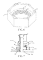
- FIG. 7 is a schematic partial sectional view of a hinge assembly 1a according to another embodiment of the present invention.
- the hinge assembly 1a includes a hinge bracket 2a capable of being fixed to the main body of the refrigeration appliance, a hinge shaft 8a connected to the hinge bracket 2a, and an adjusting part 3a sleeved on the hinge shaft 8a and connected to the hinge shaft 8a in a threaded connection manner.
- the hinge shaft 8a is connected to the hinge bracket 2a in the following manner: the hinge shaft 8a is movable in vertical direction relative to the hinge bracket 2a but is not rotatable relative to the hinge bracket 2a.
- the adjusting part 3a sits on a horizontal wall 23a of a supporting portion formed by the hinge bracket 2a.
- the hinge assembly 1a further includes a door supporting portion 62a fixed to the hinge shaft 8a in an unmovable manner, where the door supporting portion 62a is supported at a lower end of the door of the refrigeration appliance, so that the height of the door relative to the main body can vary as the height of the hinge shaft 8a changes.
- the door supporting portion 62a may be formed by a lower door closing member of a door closing unit 6a of a pair of butt cam surfaces.
- At least one concave portion 25a/convex portion can be formed on the lower end wall 36a of the adjusting part 3a, and a corresponding convex portion 35a/concave portion (not shown) is formed on the horizontal wall 23a of the hinge bracket 2a; the convex portion is capable of selectively entering into or moving out of the concave portion, which can prevent accidental rotation of the adjusting part 3a, and by properly setting the number and the positions of the concave portions and/or convex portions, the step adjustment of the door height can be achieved through coordination between the concave portions and convex portions.
- FIG. 8 is a schematic partial sectional view of a hinge assembly 1b according to a yet another embodiment of the present invention.
- a hinge shaft 8b is fixed to a hinge bracket 2b in an unmovable manner
- an adjusting part 3b is sleeved on the hinge shaft 8b
- an inner thread of the adjusting part 3b is connected to an outer thread of the hinge shaft 8b in a threaded connection manner.
- a door closing unit 6b sits on an upper end wall 37b of the adjusting part 3b, that is, a horizontal wall 62b formed by a lower end of the door closing unit 6b is engaged with the upper end wall 37b.
- the adjusting part 3b When the adjusting part 3b rotates relative to the hinge shaft 8b, the adjusting part 3b is movable vertically along the hinge shaft 8b, so that the longitudinal height of the door of the refrigeration appliance supported by the adjusting part 3b is adjusted.
- the horizontal wall 62b and the upper end wall 37b of the adjusting part 3b may form the convex portion 35b and the concave portion 25b for preventing accidental rotation of the adjusting part 3b, so as to prevent accidental rotation of the adjusting part 3b, and by properly setting the number and the positions of the concave portions and/or convex portions, the step adjustment of the door height can be achieved through coordination between the concave portions and the convex portions.
- no door closing assembly is disposed above the adjusting part 3b, and it is possible that an anti-rotation structure formed by the concave portions and the convex portions is disposed between a horizontal wall fixed to the door or forming an integral part of the door and the upper end wall 37b of the adjusting part 3b.
- FIG. 1 to FIG. 8 Various embodiments of individual parts described with reference to FIG. 1 to FIG. 8 can be combined in any given manner, so as to achieve the advantages of the present invention.
- the present invention is not limited to the illustrated embodiments, and generally, other means except the illustrated means may also be used as long as the means can achieve the same effect.
Landscapes
- Engineering & Computer Science (AREA)
- Chemical & Material Sciences (AREA)
- Combustion & Propulsion (AREA)
- Physics & Mathematics (AREA)
- Mechanical Engineering (AREA)
- Thermal Sciences (AREA)
- General Engineering & Computer Science (AREA)
- Refrigerator Housings (AREA)
- Hinges (AREA)
Abstract
Description
- The present invention relates to a refrigeration appliance, and in particular, to a refrigeration appliance having a door hinge assembly, such as a refrigerator, a wine cooler and a freezer.
- The height of a door hinged to a main body of a refrigeration appliance relative to the main body may change, and it is known that the height of the door relative to the main body is adjusted using a door hinge assembly of a height adjusting mechanism. For example,
CN102365515A discloses an adjustable hinge assembly for a pivot door, including a pivot shaft fixed to a hinge plate, an adjusting part sleeved on the pivot shaft and a locking member for maintaining the position of the adjusting part along the pivot shaft, where the pivot shaft has a thread portion and defines a rotation axis of the door, and the adjusting part has an inner thread which is rotatable along the thread portion of the pivot shaft to adjust the height of the door. During rotation, the adjusting part moves up and down, to move the door upwards or downwards. The locking member extends through one of multiple recesses arranged at an outer periphery of the adjusting part, and it is necessary to remove the locking member when the adjusting part is rotated, which not only requires additional parts of the hinge assembly but also make the door height adjustment procedure complex. In addition, as the height of the door is adjusted in a stepless manner, it is not easy for users to obtain the adjusted height of the door when the height of the door is adjusted. - An objective of the present invention is to solve the at least one technical problem described above, so as to provide a refrigeration appliance capable of preventing a door height adjusting part from accidentally rotating in a simple and reliable manner.
- Thus, one aspect of the present invention relates to a refrigeration appliance. The refrigeration appliance includes a main body, a door, and a hinge assembly connected to the door and the main body such that the door is rotatable around a rotation axis, where the hinge assembly includes an adjusting part for adjusting the height of the door relative to the main body, and having a first thread portion and an end wall at least substantially parallel to a horizontal plane; a second thread portion connected to the first thread portion in a threaded connection manner, where when the adjusting part rotates around the rotation axis, one of the first thread portion and the second thread portion is capable of moving along the other one of the first thread portion and the second thread portion in a vertical direction; and a horizontal wall, where one of the horizontal wall and the end wall at least partially sits on the other one of the horizontal wall and the end wall; the refrigeration appliance is characterized in that, one of the end wall and the horizontal wall has at least one concave portion, the other one of the end wall and the horizontal wall has at least one convex portion, and each convex portion is capable of selectively entering into or moving out of the at least one concave portion.
- Thus, when the convex portion enters into the concave portion, the possibility of accidental rotation of the adjusting part is significantly reduced, thereby reducing the possibility of undesired door height change; on the other hand, the convex portion moves out of the concave portion as long as an appropriate rotation force is applied on the adjusting part, so as to rotate the adjusting part to adjust the height of the door.
- The above objective can be achieved through the features in the independent claims. Exemplary embodiments of the present invention are subject matters of the accompanying drawings, the specification and the dependent claims.
- According to an exemplary embodiment of the present invention, one of the end wall and the horizontal wall has a plurality of concave portions, the plurality of concave portions surrounds the rotation axis, adjacent concave portions are distributed at an equal interval, and the at least one convex portion is capable of selectively entering into or moving out of any one of the concave portions. Thus, it is likely to achieve step adjustment of the height of the door.
- According to an exemplary embodiment of the present invention, the other one of the end wall and the horizontal wall has a plurality of the convex portions, the plurality of convex portions surrounds the rotation axis, and adjacent convex portions are distributed at an equal interval.
- According to an exemplary embodiment of the present invention, the adjusting part step adjusts the height of the door.
- According to an exemplary embodiment of the present invention, the concave portion and/or the convex portion are/is of an inverted cone shape.
- According to an exemplary embodiment of the present invention, the convex portion is formed on the adjusting part.
- According to an exemplary embodiment of the present invention, the horizontal wall is formed by a hinge bracket with one end connected to the main body, the end wall is a lower end wall of the adjusting part, and when the adjusting part is rotated, the end wall sits on the hinge bracket and the second thread portion moves in an upright direction.
- According to an exemplary embodiment of the present invention, the adjusting part is capable of being rotated and moving upwards to a position that is distanced from the hinge bracket.
- According to an exemplary embodiment of the present invention, the end wall is formed by an upper end wall of the adjusting part, the horizontal wall is formed by the door or a component located between the door and the upper end wall, the horizontal wall sits on the end wall, and when the adjusting part is rotated, the adjusting part moves vertically along the second thread portion.
- According to an exemplary embodiment of the present invention, a hinge shaft is included, where the second thread portion is formed by the hinge shaft.
- According to an exemplary embodiment of the present invention, a hinge shaft and a lift member sleeved on the hinge shaft are included, where the second thread portion is formed on the lift member.
- According to an exemplary embodiment of the present invention, the first thread portion is an inner thread and the second thread portion is an outer thread.
- Another aspect of the present invention relates to a refrigeration appliance. The refrigeration appliance includes a main body, a door, and a hinge assembly connected to the door and the main body such that the door is rotatable around a rotation axis, where the hinge assembly includes:
- an adjusting part for adjusting the height of the door relative to the main body and having a first thread portion and an end wall at least substantially parallel to a horizontal plane; a second thread portion connected to the first thread portion in a threaded connection manner, where when the adjusting part rotates around the rotation axis, one of the first thread portion and the second thread portion is movable along the other one of the first thread portion and the second thread portion in a vertical direction; and the refrigeration appliance is characterized in that, the adjusting part step adjusts the height of the door.
- Preferably, the refrigeration appliance includes a horizontal wall, where one of the horizontal wall and the end wall at least partially sits on the other one of the horizontal wall and the end wall; one of the end wall and the horizontal wall has a plurality of concave portions, and the other one of the end wall and the horizontal wall has at least one convex portion, where the plurality of concave portions surrounds the rotation axis and adjacent concave portions are distributed at an equal interval, and each convex portion is capable of selectively entering into or moving out of any one of concave portions.
- The structure and other invention objectives as well as beneficial effects of the present invention will be more comprehensible with reference to the accompanying drawings and the description about the exemplary embodiments.
- As a part of the specification and for facilitating further comprehension of the present invention, the following accompanying drawings illustrate specific implementation manners of the present invention, and describe the principle of the present invention together with the specification, where
-
FIG. 1 is a schematic perspective view of a refrigeration appliance according to an exemplary embodiment of the present invention; -
FIG. 2 is a schematic partial perspective view of a door and a hinge assembly of a refrigeration appliance assembled together according to an exemplary embodiment of the present invention; -
FIG. 3 is a schematic exploded view of a hinge assembly according to an exemplary embodiment of the present invention; -
FIG. 4 is a schematic sectional view of a hinge assembly according to an exemplary embodiment of the present invention; -
FIG. 5 is a schematic sectional view of a hinge assembly at another height according to an exemplary embodiment of the present invention; -
FIG. 6 is a schematic perspective view of an adjusting part according to an exemplary embodiment of the present invention; -
FIG. 7 is a schematic sectional view of a hinge assembly according to another exemplary embodiment of the present invention; and -
FIG. 8 is a schematic sectional view of a hinge assembly according to a yet another exemplary embodiment of the present invention. -
FIG. 1 is a partial perspective view of arefrigeration appliance 100 according to an exemplary embodiment of the present invention. As shown inFIG. 1 , therefrigeration appliance 100 includes amain body 101 having a storage chamber and a pair ofdoors 102 and 102' connected to themain body 101 to close or open the storage chamber. Thedoors 102 and 102' are respectively hinged to the left side and the right side of themain body 101 to open or close the corresponding storage chamber. - The
refrigeration appliance 100 includes ahinge assembly 1 respectively connected between a lower end of eachdoor 102 or 102' and themain body 101. Thehinge assembly 1 is configured such that heights of thecorresponding doors 102 and 102' relative to themain body 101 can be adjusted respectively. Thehinge assembly 1 is described below in detail by taking thehinge assembly 1 connected to thedoor 102 as an example. -
FIG. 2 is a schematic partial perspective view of a door and a hinge assembly of a refrigeration appliance assembled together according to an exemplary embodiment of the present invention; andFIG. 3 is a schematic exploded view of a hinge assembly according to an exemplary embodiment of the present invention. Referring toFIG. 2 andFIG. 3 in combination withFIG. 1 , thehinge assembly 1 includes ahinge bracket 2 with an end fixed to themain body 101, ahinge shaft 8 fixed to thehinge bracket 2 and defining a rotation axis X of thedoor 102, and an adjustingpart 3 for adjusting the height of thedoor 102 relative to themain body 101. - The
hinge bracket 2 includes a mounting portion 21 fixed to themain body 101. The mounting portion 21 may be provided with a plurality of fixing holes 22 to allow a suitable fixing part (not shown) to pass through the mounting portion to fix the hinge bracket to themain body 101. The fixing part may be a screw. In this embodiment, the mounting portion 21 is connected to a bottom face of themain body 101. In an alternative embodiment, by suitably changing the shape of the hinge bracket, the hinge bracket may also be fixed to a front surface of the main body, which is especially applicable to the situation where the hinge assembly is a middle hinge. - The
hinge bracket 2 includes a plate-shaped supportingportion 23 extending forward from the mounting portion 21. The supportingportion 23 is perpendicular to the front surface of themain body 101, and thus is a wall parallel to the horizontal plane. - The
hinge assembly 1 includes ahinge shaft 8 fixed to thehinge bracket 2, and thehinge shaft 8 defines a rotation axis of thedoor 102. In this embodiment, thehinge shaft 8 is unmovable relative to themain body 101. - The
hinge shaft 8 is fixed to the supportingportion 23 and extends upright from the supportingportion 23. During rotation of thedoor 102, thehinge shaft 8 is unmovable relative to the supportingportion 23. In this embodiment, thehinge shaft 8 and the supportingportion 23 are assembled together after being manufactured respectively. Specifically, thehinge shaft 8 passes through ashaft fixing hole 24 on the supportingportion 23 and is welded to the supportingportion 23. - The
hinge shaft 8 may include a pair ofshaft fixing holes 24 symmetric about a central axis in a longitudinal direction thereof to allow thehinge shaft 8 to simultaneously adapt to connection with thedoors 102 and 102'. - In an alternative embodiment, the
hinge shaft 8 and the supportingportion 23 also may be an integral member. - In this embodiment, the
hinge shaft 8 is a hollow cylinder, and has acentral hole 80. In an alternative embodiment, the hinge shaft also may be a solid cylinder. - An upper end of the
hinge shaft 8 extends into thedoor 102, so that thedoor 102 is rotatable around the rotation axis defined by thehinge shaft 8. - The adjusting
part 3 is sleeved outside thehinge shaft 8, and is rotatable around thehinge shaft 8 to adjust the height of thedoor 102 relative to themain body 101. The adjustingpart 3 has afirst thread portion 31 which is an inner thread. An outer peripheral surface of the adjustingpart 3 can be constructed like a screw nut to adapt to operations of standard tools such as wrenches. - The adjusting
part 3 is hollow, including alower end wall 36 and anupper end wall 37. Thelower end wall 36 and theupper end wall 37 are at least substantially parallel to the horizontal plane, which may include the situation where thelower end wall 36 and theupper end wall 37 are exactly or substantially parallel to the horizontal plane. - The adjusting
part 3 includes an adjustingportion 32 with afirst thread portion 31 formed on an inner peripheral surface. In an exemplary embodiment, the adjustingpart 3 may further include a base portion with a lower end connected to the adjustingportion 32 and with an inner diameter greater than that of the adjustingportion 32, so that a connection surface for connecting inner peripheral surfaces of the base portion 33 and the adjustingportion 32 is formed therebetween; asecond stopper portion 34 is formed on the connection surface to coordinate with the followingfirst stopper portion 5. - In this embodiment, the
second stopper portion 34 is substantially an annular wall, which may be substantially perpendicular to the rotation axis X. The inner surface of the base portion 33 may be smooth. - The
hinge assembly 1 includes alift member 4 connected to the adjustingpart 3 in a threaded connection manner. Thelift member 4 has a throughhole 40 running through thelift member 4 in a direction of the rotation axis X to sleeve thehinge shaft 8, and has asecond thread portion 41 which is an outer thread coordinating with thefirst thread portion 31. Thesecond thread portion 41 is formed by ahollow cylinder portion 42 of thelift member 4. In a radial direction, thecylinder portion 42 is inserted into the adjustingpart 3 and is hence located between thehinge shaft 8 and the adjustingpart 3. - The
door 102 is supported by an upper end surface of thelift member 4. Thelift member 4 also may have a platform portion 43 for increasing the area of the upper end surface of thelift member 4. - The
lift member 4 is connected to thehinge shaft 8 in a manner of being not rotatable relative to thehinge shaft 8. In this embodiment, an anti-rotation structure for preventing thelift member 4 from rotating with respect to thehinge shaft 8 includes agroove 81 formed by thehinge shaft 8 and extending in a direction of the rotation axis X, and a protruding portion 44 formed by the lift member, protruding from an inner peripheral surface of the throughhole 40 and extending into thegroove 81. The protruding portion 44 may extend along the entire axial length of thelift member 4. - In an alternative embodiment, the anti-rotation structure also may include a groove formed by the lift member and extending in a direction of the rotation axis X, and a protruding portion protruding from an outer peripheral surface of the hinge shaft and extending into the groove.
- The
hinge assembly 1 also may include afirst stopper portion 5 connected to a lower end of thelift member 4. Thefirst stopper portion 5 protrudes outwards from an outer peripheral surface of thelift member 4 and is overlapped with thesecond stopper portion 34 in the direction of the rotation axis X. Thus, thelift member 4 having thefirst stopper portion 5 cannot enter into the hole of the adjustingportion 32 of the adjustingpart 3 but is movable vertically in the hole of thebase portion 3 of the adjustingpart 3. - In an exemplary embodiment, the
first stopper portion 5 is formed by a stopper ring sleeved on thelift member 4. The lower end of thecylinder portion 41 may form a circle of retaininggroove 45 recessed in the radial direction, and the stopper ring is sandwiched in the retaininggroove 45 so as to prevent the stopper ring from moving in the direction of the rotation axis X. - In assembling, the adjusting
part 3 is first screwed onto thelift member 4, and it would be best if the end of thelift member 4 extends out of the adjustingpart 3, so as to connect thefirst stopper portion 5 to the lower end of thelift member 4. Then, the assembled adjustingpart 3, thelift member 4 and thefirst stopper portion 4 are sleeved on thehinge shaft 8. At this time, thelift member 4 can be directly supported on thehinge bracket 2, and spacing may be even formed between the adjustingpart 3 and thehinge bracket 2. - The
hinge assembly 1 may further include adoor closing unit 6 between thelift member 4 and the bottom of thedoor 102. Thedoor closing unit 6 may include an upperdoor closing part 61 fixed to the bottom of thedoor 102 in an unmovable manner and a lowerdoor closing part 62 connected to the upper end of thelift member 4; the upperdoor closing part 61 and the lowerdoor closing part 62 each have a cam surface and the cam surfaces contact with each other face to face. - The lower
door closing part 62 is fixed to thelift member 4 in a manner of being not rotatable relative to thelift member 4. In an exemplary embodiment, holes may be respectively provided on the lowerdoor closing part 62 and theplatform portion 42 of thelift member 4, and a fixing part (not shown, for example, a screw) passes through the two holes to fix the lowerdoor closing part 62 and thelift member 4 together. In an alternative embodiment, one or more protruding portions spaced apart and protruding toward opposite sides also may be formed on one of thelift member 4 and the lowerdoor closing part 62, and a corresponding pit/hole is provided on the other one of thelift member 4 and the lowerdoor closing part 62 so as to form a plug-in connection, thereby preventing thelift member 4 from rotating relative to the lowerdoor closing part 62. - In an alternative embodiment, it is likely that the lower
door closing part 62 is integrally formed on thelift member 4. - The upper
door closing part 61 may further include asleeve portion 611 sleeved on thehinge shaft 8. - When the
hinge assembly 1 is connected to thedoor 102 and themain body 101, thelift member 4 can sit on thehinge bracket 2 to be directly supported by thehinge bracket 2, and spacing may be formed between the adjustingpart 3 and thehinge bracket 2 so that the adjustingpart 3 is in a resting state. As the weight of thedoor 102 is directly supported by thehinge bracket 2 at this time, rather than being supported by thefirst thread portion 31 and thesecond thread portion 42 which are connected in a threaded connection manner, such a situation is particularly conductive to reducing the probability of damage to thefirst thread portion 31 and thesecond thread portion 42 caused by possible up and down vibration of thedoor 102 during transport of therefrigeration appliance 100. - When it is necessary to adjust the height of the
door 102 relative to themain body 101, the adjustingpart 3 may be rotated along a first direction (e.g., clockwise), and the adjustingpart 3 moves downwards along thelift member 4 until the adjustingpart 3 contacts with thehinge bracket 2, as shown inFIG. 4 . In the process, thelift member 4 stands still, the height of thedoor 102 supported by thelift member 4 relative to themain body 101 is also unchanged, and at this time, thelift member 4 and thedoor 102 are both at a lowest position in a door adjustment range decided by the adjustingpart 3. - After the adjusting
part 3 sits on thehinge bracket 2, the adjustingpart 3 is in an adjustment state capable of adjusting the height of thedoor 102. If the adjustingpart 3 continues to be rotated along the first direction, the adjustingpart 3 remains sitting on the hinge bracket 2 (i.e., keeps contact with the hinge bracket) and drives, through the coordination between thefirst thread portion 31 and thesecond thread portion 41, thelift member 4 to move upwards along thehinge shaft 8 so as to push thedoor 102 to move upwards. In the process, a distance between thelift member 4 and thehinge bracket 2 gradually increases, and thedoor 102 is gradually lifted. - When the
lift member 4 moves upwards to thefirst stopper portion 5 which moves up with thelift member 4 to contact with thesecond stopper portion 34 of the adjustingpart 3, thelift member 4 cannot continue to move up, and the adjustingpart 3 that sits on thehinge bracket 2 cannot continue to rotate in the first direction. As shown inFIG. 5 , thelift member 4 moves upwards to the maximum height. Thelift member 4 and thedoor 102 are adjusted to a highest position in the door adjustment range decided by the adjustingpart 3. - Preferably, when the
lift member 4 moves upwards to the maximum height, all threads of thefirst thread portion 31 and the thread of thesecond thread portion 41 still maintain the threaded connection. - When it is necessary to lower the height of the
door 102, the adjustingpart 3 that sits on thehinge bracket 2 may be rotated along a second direction (e.g., counterclockwise) opposite to the first direction, and thelift member 4 is driven to move down along thehinge shaft 8, so that thedoor 102 supported by thelift member 4 moves downwards together. When the lower end of thelift member 4 directly contacts with thehinge bracket 2, thelift member 4 and thedoor 102 supported by thelift member 4 reach the lowest position. - When the
lift member 4 directly sits on thehinge bracket 2, if the adjustingpart 3 continues to be rotated in the second direction, the adjusting part can move upwards along thesecond thread portion 41 of thelift member 4 to form spacing with thehinge bracket 2 and hence be suspended, and thelift member 4 remains sitting on thehinge bracket 2. At this time, the adjustingpart 3 is in a resting state, and thelift member 4 remains in the lowest position. As stated above, by rotating the adjustingpart 3 in the first direction, the suspended adjustingpart 3 can be moved down along thelift member 4 until the adjusting part contacts with thehinge bracket 2. - According to an embodiment of the present invention, when the height of the
door 102 is adjusted, the adjustingpart 3 is always in contact with thehinge bracket 2, to drive thelift member 4 to move up or down in the direction of the rotation axis X; moreover, after thelift member 4 reaches the lowest position, thelift member 4 may sit on thehinge bracket 2, and if the adjustingpart 3 is rotated along a predetermined direction, the adjustingpart 3 may move upwards along thelift member 4 which stands still to the suspended state without bearing the weight of thedoor 102, thereby avoiding, for example, damage to threads of the adjustingpart 3 and thelift member 4 during transport; furthermore, when thelift member 4 moves upwards to thefirst stopper portion 5 and butts against thesecond stopper portion 34, thelift member 4 cannot continue to move upwards, thereby avoiding the situation where the adjustingpart 3 is rotated excessively to cause the adjustingpart 3 and thelift member 4 to fall off. - In an exemplary embodiment, referring to
FIG. 3 to FIG. 6 , the upper surface of thehinge bracket 2 has a plurality ofconcave portions 25 surrounding theshaft fixing hole 24 and disposed at intervals. Theconcave portions 25 can be distributed in a common concentric ring. The lower end surface of the adjustingpart 3 is provided with a plurality ofconvex portions 35, and each of theconvex portions 35 can be at least partially received in any one of theconcave portions 25. In an alternative embodiment, the adjustingpart 3 also may be provided with oneconcave portion 25 or twoconvex portions 35 which are distributed symmetrically about the central axis of the adjustingpart 3. - When the adjusting
part 3 is rotated, each of theconvex portions 35 moves out of an originalconcave portion 25 and rotates along the upper surface of thehinge bracket 2, until the convex portion falls into aconcave portion 25 adjacent to the originalconcave portion 25, and this will give an obvious feeling of indication to a user/worker operating the adjusting part. - The
concave portions 25 are distributed at an equal interval. That is to say, each time the adjustingpart 3 is rotated to a predetermined angle (i.e., the height of thedoor 102 is correspondingly adjusted to a predetermined height), the user can evidently feel slight height change of the adjustingpart 3 in the longitudinal direction and change of force required for rotating the adjustingpart 3 again as theconvex portions 35 falls into theconcave portions 25. That is to say, the user can adjust the height of thedoor 102 from stage to stage according to a predetermined step. In the embodiment shown inFIG. 3 , eachshaft fixing hole 24 corresponds to sixconcave portions 25 distributed at an equal interval, that is to say, at each step the user needs to rotate the adjustingpart 3 by 60 degrees. - As shown in
FIG. 6 , it would be best if eachconvex portion 35 is of an inverted conical shape, and the cone top is chamfered for transition. Theconcave portion 25 may also be constructed as an inverted cone that adapts to matching with theconvex portion 35. The cone angle of theconcave portion 25 and theconvex portions 35 is preferably greater than 90 degrees, for example, 90 degrees to 120 degrees. - The height of the
concave portion 25 and theconvex portions 35 is preferably lower than 1 mm, for example, 0.5 mm to 0.7 mm. - In addition, with the plug-in connection between the
convex portions 35 and theconcave portions 25, the adjustingpart 3 can adjust the height of thedoor 102 from stage to stage according to a predetermined amplitude; in the event that no large rotation force is applied to the adjustingpart 3, the adjustingpart 3 does not rotate, that is to say, accidental rotation of the adjustingpart 3 can be avoided. - In an alternative embodiment, the concave portions also may be formed on the lower end surface of the adjusting part, and the convex portions are formed on the hinge bracket.
- When it is unnecessary to step adjust the height of the
door 102, only a pair of the concave portion and convex portion in butt joint may exist between the adjustingpart 3 and the supportingportion 23. - In the above embodiments, when the adjusting
part 3 is rotated, thelower end wall 36 of the adjustingpart 3 sits on a horizontal wall formed by the supportingportion 23 of thehinge bracket 2, and thesecond thread portion 41 coordinating with thefirst thread portion 31 of the adjustingpart 3 moves vertically along thefirst thread portion 31 to change the height of thedoor 102 relative to themain body 101,where thedoor 102 is lifted by the lift member forming thesecond thread portion 41. Therefore, convex portions and concave portions for preventing accidental rotation of the adjustingpart 3 and/or for step adjustment of the door height are disposed on the lower end wall of the adjustingpart 3 and the hinge bracket. However, applications of the convex portions and concave portions for preventing accidental rotation of the adjustingpart 3 and/or for step adjustment of the door height should not be limited thereto, and applications may also go to other occasions, for example, the scheme that the adjusting part moves in an upright direction when the adjusting part rotates and/or the second thread portion is directly formed on the hinge shaft. -
FIG. 7 is a schematic partial sectional view of a hinge assembly 1a according to another embodiment of the present invention. As shown inFIG. 7 , the hinge assembly 1a includes ahinge bracket 2a capable of being fixed to the main body of the refrigeration appliance, ahinge shaft 8a connected to thehinge bracket 2a, and an adjustingpart 3a sleeved on thehinge shaft 8a and connected to thehinge shaft 8a in a threaded connection manner. Thehinge shaft 8a is connected to thehinge bracket 2a in the following manner: thehinge shaft 8a is movable in vertical direction relative to thehinge bracket 2a but is not rotatable relative to thehinge bracket 2a. - The adjusting
part 3a sits on ahorizontal wall 23a of a supporting portion formed by thehinge bracket 2a. The hinge assembly 1a further includes adoor supporting portion 62a fixed to thehinge shaft 8a in an unmovable manner, where thedoor supporting portion 62a is supported at a lower end of the door of the refrigeration appliance, so that the height of the door relative to the main body can vary as the height of thehinge shaft 8a changes. Thedoor supporting portion 62a may be formed by a lower door closing member of adoor closing unit 6a of a pair of butt cam surfaces. - When the adjusting
part 3a rotates, thehinge shaft 8a moves vertically along the thread of the adjustingpart 3a, so as to change the height of the door. At least oneconcave portion 25a/convex portion can be formed on thelower end wall 36a of the adjustingpart 3a, and a correspondingconvex portion 35a/concave portion (not shown) is formed on thehorizontal wall 23a of thehinge bracket 2a; the convex portion is capable of selectively entering into or moving out of the concave portion, which can prevent accidental rotation of the adjustingpart 3a, and by properly setting the number and the positions of the concave portions and/or convex portions, the step adjustment of the door height can be achieved through coordination between the concave portions and convex portions. -
FIG. 8 is a schematic partial sectional view of a hinge assembly 1b according to a yet another embodiment of the present invention. As shown inFIG. 8 , ahinge shaft 8b is fixed to ahinge bracket 2b in an unmovable manner, an adjustingpart 3b is sleeved on thehinge shaft 8b, and an inner thread of the adjustingpart 3b is connected to an outer thread of thehinge shaft 8b in a threaded connection manner. Adoor closing unit 6b sits on anupper end wall 37b of the adjustingpart 3b, that is, ahorizontal wall 62b formed by a lower end of thedoor closing unit 6b is engaged with theupper end wall 37b. - When the adjusting
part 3b rotates relative to thehinge shaft 8b, the adjustingpart 3b is movable vertically along thehinge shaft 8b, so that the longitudinal height of the door of the refrigeration appliance supported by the adjustingpart 3b is adjusted. Thehorizontal wall 62b and theupper end wall 37b of the adjustingpart 3b may form theconvex portion 35b and theconcave portion 25b for preventing accidental rotation of the adjustingpart 3b, so as to prevent accidental rotation of the adjustingpart 3b, and by properly setting the number and the positions of the concave portions and/or convex portions, the step adjustment of the door height can be achieved through coordination between the concave portions and the convex portions. In an alternative embodiment, no door closing assembly is disposed above the adjustingpart 3b, and it is possible that an anti-rotation structure formed by the concave portions and the convex portions is disposed between a horizontal wall fixed to the door or forming an integral part of the door and theupper end wall 37b of the adjustingpart 3b. - Various embodiments of individual parts described with reference to
FIG. 1 to FIG. 8 can be combined in any given manner, so as to achieve the advantages of the present invention. In addition, the present invention is not limited to the illustrated embodiments, and generally, other means except the illustrated means may also be used as long as the means can achieve the same effect.
Claims (14)
- A refrigeration appliance (100), comprising a main body (101), a door (102, 102'), and a hinge assembly (1, 1a, 1b) connected to the door (102, 102') and the main body (101) such that the door (102, 102') is rotatable around a rotation axis (X), wherein the hinge assembly (1, 1a, 1b) comprises:an adjusting part (3, 3a, 3b) for adjusting the height of the door (102, 102') relative to the main body (101), and having a first thread portion (31) and an end wall (36, 36a, 37b) at least substantially parallel to a horizontal plane;a second thread portion (41) is connected to the first thread portion (31) in a threaded connection manner, wherein when the adjusting part (3, 3a, 3b) rotates around the rotation axis (X), one of the first thread portion (31) and the second thread portion (41) is capable of moving along the other one of the first thread portion (31) and the second thread portion (41) in a vertical direction; anda horizontal wall (23, 23a, 62b), wherein one of the horizontal wall (23, 23a, 62b) and the end wall (36, 36a, 37b) at least partially sits on the other one of the horizontal wall (23, 23a, 62b) and the end wall (36, 36a, 37b),characterized in that, one of the end wall (36, 36a, 37b) and the horizontal wall (23, 23a, 62b) has at least one concave portion (25, 25a, 25b), the other one of the end wall (36, 36a, 37b) and the horizontal wall (23, 23a, 62b) has at least one convex portion (35, 35a, 35b), and each convex portion (35, 35a, 35b) is capable of selectively entering into or moving out of the at least one concave portion (25, 25a, 25b).
- The refrigeration appliance (100) according to claim 1, characterized in that, one of the end wall (36, 36a, 37b) and the horizontal wall (23, 23a, 62b) has a plurality of concave portions (25, 25a, 25b), the plurality of concave portions (25, 25a, 25b) surrounds the rotation axis (X), adjacent concave portions (25) are distributed at an equal interval, and the at least one convex portion (35, 35a, 35b) is capable of selectively entering into or moving out of any one of the concave portions (25, 25a, 25b).
- The refrigeration appliance (100) according to claim 2, characterized in that, the other one of the end wall (36, 36a, 37b) and the horizontal wall (23, 23a, 62b) has a plurality of the convex portions (35, 35a, 35b), the plurality of convex portions (35, 35a, 35b) surrounds the rotation axis (X), and adjacent convex portions (35, 35a, 35b) are distributed at an equal interval.
- The refrigeration appliance (100) according to claim 1, characterized in that, the adjusting part (3, 3a, 3b) step adjusts the height of the door (102, 102').
- The refrigeration appliance (100) according to any one of claims 1 to 4, characterized in that, the concave portion (25, 25a, 25b) and/or the convex portion (35, 35a, 35b) is of an inverted cone shape.
- The refrigeration appliance (100) according to any one of claims 1 to 5, characterized in that, the convex portion (35, 35b) is formed on the adjusting part (3, 3b).
- The refrigeration appliance (100) according to any one of claims 1 to 6, characterized in that, the horizontal wall (23, 23a) is formed by a hinge bracket (2, 2a) with one end connected to the main body (101), the end wall (36, 36a) is a lower end wall of the adjusting part (3, 3a), and when the adjusting part (3, 3a) is rotated, the end wall (36, 36a) sits on the hinge bracket (2, 2a) and the second thread portion (41) moves in an upright direction.
- The refrigeration appliance (100) according to claim 7, characterized in that, the adjusting part (3) is capable of being rotated and moving upwards to a position that is distanced from the hinge bracket (2, 2a).
- The refrigeration appliance (100) according to any one of claims 1 to 6, characterized in that, the end wall (37b) is formed by an upper end wall of the adjusting part (3b), the horizontal wall (62b) is formed by the door or a component (6b) located between the door and the upper end wall, the horizontal wall (62b) sits on the end wall (37b), and when the adjusting part (3b) is rotated, the adjusting part (3b) moves vertically along the second thread portion.
- The refrigeration appliance (100) according to any one of claims 1 to 9, characterized by further comprising a hinge shaft (8a, 8b), wherein the second thread portion is formed by the hinge shaft (8a, 8b).
- The refrigeration appliance (100) according to any one claims 1 to 9, characterized by further comprising a hinge shaft (8) and a lift member (4) sleeved on the hinge shaft (8), wherein the second thread portion (41) is formed on the lift member (4).
- The refrigeration appliance (100) according to any one of claims 1 to 4, characterized in that, the first thread portion (31) is an inner thread and the second thread portion (41) is an outer thread.
- A refrigeration appliance (100), comprising a main body (101), a door (102, 102'), and a hinge assembly (1, 1a, 1b) connected to the door (102, 102') and the main body (101) such that the door (102, 102') is rotatable around a rotation axis (X), wherein the hinge assembly (1, 1a, 1b) comprises:an adjusting part (3, 3a, 3b) for adjusting the height of the door (102, 102') relative to the main body (101) and having a first thread portion (31) and an end wall (36, 36a, 37b) at least substantially parallel to a horizontal plane;a second thread portion (41) connected to the first thread portion (31) in a threaded connection manner, wherein when the adjusting part (3, 3a, 3b) rotates around the rotation axis (X), one of the first thread portion (31) and the second thread portion (41) is movable along the other one of the first thread portion (31) and the second thread portion (41) in a vertical direction,characterized in that, the adjusting part (3, 3a, 3b) is step adjusts the height of the door (102, 102').
- The refrigeration appliance (100) according to claim 13, characterized by further comprising a horizontal wall (23, 23a, 62b), wherein one of the horizontal wall (23, 23a, 62b) and the end wall (36, 36a, 37b) at least partially sits on the other one of the horizontal wall (23, 23a, 62b) and the end wall (36, 36a, 37b),
and further characterized in that, one of the end wall (36, 36a, 37b) and the horizontal wall (23, 23a, 62b) has a plurality of concave portions (25, 25a, 25b), the other one of the end wall (36, 36a, 37b) and the horizontal wall (23, 23a, 62b) has at least one convex portion (35, 35a, 35b), wherein the plurality of concave portions (25, 25a, 25b) surrounds the rotation axis (X) and adjacent concave portions (25) are distributed at an equal interval, and each convex portion (35, 35a, 35b) is capable of selectively entering into or moving out of any one of concave portions (25, 25a, 25b).
Applications Claiming Priority (1)
| Application Number | Priority Date | Filing Date | Title |
|---|---|---|---|
| CN201210486612.7A CN103836874B (en) | 2012-11-21 | 2012-11-21 | Refrigerating appliance with door hinge components |
Publications (1)
| Publication Number | Publication Date |
|---|---|
| EP2735828A1 true EP2735828A1 (en) | 2014-05-28 |
Family
ID=49554140
Family Applications (1)
| Application Number | Title | Priority Date | Filing Date |
|---|---|---|---|
| EP13192476.3A Withdrawn EP2735828A1 (en) | 2012-11-21 | 2013-11-12 | Refrigeration appliance having door hinge assembly |
Country Status (2)
| Country | Link |
|---|---|
| EP (1) | EP2735828A1 (en) |
| CN (1) | CN103836874B (en) |
Cited By (4)
| Publication number | Priority date | Publication date | Assignee | Title |
|---|---|---|---|---|
| US20140306595A1 (en) * | 2013-04-12 | 2014-10-16 | Samsung Electronics Co., Ltd. | Refrigerator |
| DE102015201439A1 (en) | 2015-01-28 | 2016-07-28 | P & L Gmbh & Co. Kg | Method for compensating deformations of a rotary pivot unit of a machine tool due to dynamic movement processes |
| WO2018127163A1 (en) * | 2017-01-09 | 2018-07-12 | 青岛海尔股份有限公司 | Storage device |
| US20210238900A1 (en) * | 2020-02-03 | 2021-08-05 | Samsung Electronics Co., Ltd. | Refrigerator |
Families Citing this family (3)
| Publication number | Priority date | Publication date | Assignee | Title |
|---|---|---|---|---|
| CN104929461A (en) * | 2015-06-03 | 2015-09-23 | 合肥美的电冰箱有限公司 | Levelling mechanism and side-by-side combination refrigerator with same |
| CN110118465B (en) * | 2018-02-05 | 2022-05-10 | Bsh家用电器有限公司 | Domestic refrigeration appliance with a specific height adjustment for the door |
| CN112384674B (en) * | 2018-05-10 | 2023-03-03 | 斯维洛克斯集团股份公司 | Pivoting door |
Citations (4)
| Publication number | Priority date | Publication date | Assignee | Title |
|---|---|---|---|---|
| US20050262663A1 (en) * | 2004-05-27 | 2005-12-01 | Lg Electronics Inc. | Door hinge apparatus of refrigerator |
| WO2009131295A2 (en) * | 2008-04-23 | 2009-10-29 | Lg Electronics Inc. | Refrigerator |
| US20110140585A1 (en) * | 2009-12-16 | 2011-06-16 | Lg Electronics Inc. | Refrigerator |
| CN102365515A (en) | 2009-02-27 | 2012-02-29 | 伊莱克斯家用产品公司 | Adjustable hinge for pivoting door |
Family Cites Families (1)
| Publication number | Priority date | Publication date | Assignee | Title |
|---|---|---|---|---|
| CN201695831U (en) * | 2010-06-11 | 2011-01-05 | 合肥美的荣事达电冰箱有限公司 | Hinge device for refrigerators |
-
2012
- 2012-11-21 CN CN201210486612.7A patent/CN103836874B/en active Active
-
2013
- 2013-11-12 EP EP13192476.3A patent/EP2735828A1/en not_active Withdrawn
Patent Citations (4)
| Publication number | Priority date | Publication date | Assignee | Title |
|---|---|---|---|---|
| US20050262663A1 (en) * | 2004-05-27 | 2005-12-01 | Lg Electronics Inc. | Door hinge apparatus of refrigerator |
| WO2009131295A2 (en) * | 2008-04-23 | 2009-10-29 | Lg Electronics Inc. | Refrigerator |
| CN102365515A (en) | 2009-02-27 | 2012-02-29 | 伊莱克斯家用产品公司 | Adjustable hinge for pivoting door |
| US20110140585A1 (en) * | 2009-12-16 | 2011-06-16 | Lg Electronics Inc. | Refrigerator |
Cited By (6)
| Publication number | Priority date | Publication date | Assignee | Title |
|---|---|---|---|---|
| US20140306595A1 (en) * | 2013-04-12 | 2014-10-16 | Samsung Electronics Co., Ltd. | Refrigerator |
| US9291385B2 (en) * | 2013-04-12 | 2016-03-22 | Samsung Electronics Co., Ltd. | Refrigerator |
| DE102015201439A1 (en) | 2015-01-28 | 2016-07-28 | P & L Gmbh & Co. Kg | Method for compensating deformations of a rotary pivot unit of a machine tool due to dynamic movement processes |
| WO2018127163A1 (en) * | 2017-01-09 | 2018-07-12 | 青岛海尔股份有限公司 | Storage device |
| US20210238900A1 (en) * | 2020-02-03 | 2021-08-05 | Samsung Electronics Co., Ltd. | Refrigerator |
| US11578519B2 (en) * | 2020-02-03 | 2023-02-14 | Samsung Electronics Co., Ltd. | Refrigerator |
Also Published As
| Publication number | Publication date |
|---|---|
| CN103836874B (en) | 2019-04-26 |
| CN103836874A (en) | 2014-06-04 |
Similar Documents
| Publication | Publication Date | Title |
|---|---|---|
| EP2735828A1 (en) | Refrigeration appliance having door hinge assembly | |
| EP2735680A2 (en) | Refrigeration appliance having door hinge assembly | |
| EP2972022B1 (en) | Adjustable hinge for mounting a door on a cabinet | |
| KR101504241B1 (en) | Caster and white board having the caster | |
| KR20050028265A (en) | Device for lifting shelf for refrigerator | |
| US9481207B2 (en) | Adjustable sleeve for rolling support device | |
| KR102149107B1 (en) | Height adjustable furniture leg | |
| EP3584457B1 (en) | Supporting foot assembly | |
| CN109838953B (en) | Household appliance and hinge unit thereof | |
| US5749557A (en) | Height adjusting device for a chair | |
| JP5008920B2 (en) | Furniture legs | |
| KR20180136194A (en) | Kickstand of furniture | |
| KR101709554B1 (en) | Kickstand of furniture | |
| KR101066110B1 (en) | Height adjustable type table | |
| KR20090078882A (en) | Tilt adjusting device for desk plate | |
| US11510501B2 (en) | Position adjustment mechanism for lifting balance device | |
| EP2735679B1 (en) | Adjustable hinge for doors and windows or furniture | |
| US6916067B2 (en) | Angle adjusting mechanism for chair | |
| JP7335120B2 (en) | Casters and caster fixtures | |
| KR200402515Y1 (en) | Structure for Connecting Leg of Gas Range for Commercial Use | |
| KR20170047600A (en) | Coner shelf | |
| KR101720456B1 (en) | a connecting apparatus for lower end part of the leg | |
| CN103573074A (en) | Hinge for refrigerator and refrigerator comprising hinge | |
| KR20140084716A (en) | Joint apparatus of robot | |
| KR102482813B1 (en) | Prop assembly for article |
Legal Events
| Date | Code | Title | Description |
|---|---|---|---|
| PUAI | Public reference made under article 153(3) epc to a published international application that has entered the european phase |
Free format text: ORIGINAL CODE: 0009012 |
|
| 17P | Request for examination filed |
Effective date: 20131112 |
|
| AK | Designated contracting states |
Kind code of ref document: A1 Designated state(s): AL AT BE BG CH CY CZ DE DK EE ES FI FR GB GR HR HU IE IS IT LI LT LU LV MC MK MT NL NO PL PT RO RS SE SI SK SM TR |
|
| AX | Request for extension of the european patent |
Extension state: BA ME |
|
| R17P | Request for examination filed (corrected) |
Effective date: 20141128 |
|
| RBV | Designated contracting states (corrected) |
Designated state(s): AL AT BE BG CH CY CZ DE DK EE ES FI FR GB GR HR HU IE IS IT LI LT LU LV MC MK MT NL NO PL PT RO RS SE SI SK SM TR |
|
| RAP1 | Party data changed (applicant data changed or rights of an application transferred) |
Owner name: BSH HAUSGERAETE GMBH |
|
| GRAP | Despatch of communication of intention to grant a patent |
Free format text: ORIGINAL CODE: EPIDOSNIGR1 |
|
| INTG | Intention to grant announced |
Effective date: 20181123 |
|
| STAA | Information on the status of an ep patent application or granted ep patent |
Free format text: STATUS: THE APPLICATION IS DEEMED TO BE WITHDRAWN |
|
| 18D | Application deemed to be withdrawn |
Effective date: 20190404 |