EP2735697A1 - Method and system for inhibiting contact of a corrosive displacement gas with corrosion prone natural gas production facilities - Google Patents
Method and system for inhibiting contact of a corrosive displacement gas with corrosion prone natural gas production facilities Download PDFInfo
- Publication number
- EP2735697A1 EP2735697A1 EP12194473.0A EP12194473A EP2735697A1 EP 2735697 A1 EP2735697 A1 EP 2735697A1 EP 12194473 A EP12194473 A EP 12194473A EP 2735697 A1 EP2735697 A1 EP 2735697A1
- Authority
- EP
- European Patent Office
- Prior art keywords
- corrosive
- formation
- gas
- displacement
- natural gas
- Prior art date
- Legal status (The legal status is an assumption and is not a legal conclusion. Google has not performed a legal analysis and makes no representation as to the accuracy of the status listed.)
- Withdrawn
Links
- VNWKTOKETHGBQD-UHFFFAOYSA-N methane Chemical compound C VNWKTOKETHGBQD-UHFFFAOYSA-N 0.000 title claims abstract description 103
- 239000007789 gas Substances 0.000 title claims abstract description 66
- 239000003345 natural gas Substances 0.000 title claims abstract description 48
- 238000006073 displacement reaction Methods 0.000 title claims abstract description 45
- 238000004519 manufacturing process Methods 0.000 title claims abstract description 35
- 238000005260 corrosion Methods 0.000 title claims abstract description 10
- 230000007797 corrosion Effects 0.000 title claims abstract description 10
- 238000000034 method Methods 0.000 title claims description 28
- 230000002401 inhibitory effect Effects 0.000 title description 3
- IJGRMHOSHXDMSA-UHFFFAOYSA-N Atomic nitrogen Chemical compound N#N IJGRMHOSHXDMSA-UHFFFAOYSA-N 0.000 claims abstract description 71
- 230000015572 biosynthetic process Effects 0.000 claims abstract description 57
- 230000009972 noncorrosive effect Effects 0.000 claims abstract description 19
- 238000002347 injection Methods 0.000 claims abstract description 14
- 239000007924 injection Substances 0.000 claims abstract description 14
- 230000004888 barrier function Effects 0.000 claims abstract description 4
- 229910052757 nitrogen Inorganic materials 0.000 claims description 32
- CURLTUGMZLYLDI-UHFFFAOYSA-N Carbon dioxide Chemical compound O=C=O CURLTUGMZLYLDI-UHFFFAOYSA-N 0.000 claims description 28
- XLYOFNOQVPJJNP-UHFFFAOYSA-N water Substances O XLYOFNOQVPJJNP-UHFFFAOYSA-N 0.000 claims description 17
- 239000001569 carbon dioxide Substances 0.000 claims description 14
- 229910002092 carbon dioxide Inorganic materials 0.000 claims description 14
- QVGXLLKOCUKJST-UHFFFAOYSA-N atomic oxygen Chemical compound [O] QVGXLLKOCUKJST-UHFFFAOYSA-N 0.000 claims description 9
- 239000001301 oxygen Substances 0.000 claims description 9
- 229910052760 oxygen Inorganic materials 0.000 claims description 9
- 239000011148 porous material Substances 0.000 claims description 9
- 238000000926 separation method Methods 0.000 claims description 9
- 239000003546 flue gas Substances 0.000 claims description 8
- 230000002708 enhancing effect Effects 0.000 claims description 7
- 239000000203 mixture Substances 0.000 claims description 7
- 239000000446 fuel Substances 0.000 claims description 5
- UGFAIRIUMAVXCW-UHFFFAOYSA-N Carbon monoxide Chemical compound [O+]#[C-] UGFAIRIUMAVXCW-UHFFFAOYSA-N 0.000 claims description 3
- 239000010779 crude oil Substances 0.000 claims 2
- 239000003921 oil Substances 0.000 claims 1
- 238000005755 formation reaction Methods 0.000 description 34
- 238000005516 engineering process Methods 0.000 description 3
- 238000009825 accumulation Methods 0.000 description 2
- 239000003079 shale oil Substances 0.000 description 2
- 241000237858 Gastropoda Species 0.000 description 1
- 239000006227 byproduct Substances 0.000 description 1
- 239000003153 chemical reaction reagent Substances 0.000 description 1
- 239000003795 chemical substances by application Substances 0.000 description 1
- 239000000470 constituent Substances 0.000 description 1
- 239000012530 fluid Substances 0.000 description 1
- 230000004907 flux Effects 0.000 description 1
- 239000005431 greenhouse gas Substances 0.000 description 1
- 229930195733 hydrocarbon Natural products 0.000 description 1
- 150000002430 hydrocarbons Chemical class 0.000 description 1
- 239000007788 liquid Substances 0.000 description 1
- 230000005012 migration Effects 0.000 description 1
- 238000013508 migration Methods 0.000 description 1
- JCXJVPUVTGWSNB-UHFFFAOYSA-N nitrogen dioxide Inorganic materials O=[N]=O JCXJVPUVTGWSNB-UHFFFAOYSA-N 0.000 description 1
- QJGQUHMNIGDVPM-UHFFFAOYSA-N nitrogen group Chemical group [N] QJGQUHMNIGDVPM-UHFFFAOYSA-N 0.000 description 1
- 230000008569 process Effects 0.000 description 1
- 238000011084 recovery Methods 0.000 description 1
- 238000010792 warming Methods 0.000 description 1
Images

Classifications
-
- E—FIXED CONSTRUCTIONS
- E21—EARTH OR ROCK DRILLING; MINING
- E21B—EARTH OR ROCK DRILLING; OBTAINING OIL, GAS, WATER, SOLUBLE OR MELTABLE MATERIALS OR A SLURRY OF MINERALS FROM WELLS
- E21B43/00—Methods or apparatus for obtaining oil, gas, water, soluble or meltable materials or a slurry of minerals from wells
- E21B43/16—Enhanced recovery methods for obtaining hydrocarbons
- E21B43/164—Injecting CO2 or carbonated water
-
- E—FIXED CONSTRUCTIONS
- E21—EARTH OR ROCK DRILLING; MINING
- E21B—EARTH OR ROCK DRILLING; OBTAINING OIL, GAS, WATER, SOLUBLE OR MELTABLE MATERIALS OR A SLURRY OF MINERALS FROM WELLS
- E21B43/00—Methods or apparatus for obtaining oil, gas, water, soluble or meltable materials or a slurry of minerals from wells
- E21B43/16—Enhanced recovery methods for obtaining hydrocarbons
- E21B43/166—Injecting a gaseous medium; Injecting a gaseous medium and a liquid medium
Definitions
- the invention relates to a method and system for inhibiting contact of a corrosive displacement gas with corrosion prone natural gas production facilities.
- US patent 4,765,407 discloses a method for enhancing production of gas condensates from a gas condensate reservoir by injecting a mixture of carbon dioxide and nitrogen obtained from a Claus plant into the reservoir.
- a disadvantage of this known injection technology is that a mixture of carbon dioxide and nitrogen is corrosive and will induce corrosion of corrosion prone fluid injection and production facilities.
- Canadian patent application CA 2568358 discloses a method for fracturing a hydrate or shale oil containing formation by injecting liquid nitrogen into the formation.
- a limitation of the known nitrogen displacement gas technologies is that they are either configured to enhance production from gas condensate, hydrate and/or shale oil containing formations or from tight reservoirs by fracturing and that they are not configured inject a large volume of displacement gas into a formation to enhance natural gas production from the formation.
- a further limitation of the know nitrogen displacement gas injection technologies is that generation of displacement gas in Air Separation Units or other available displacement gas generation devices is expensive.
- a method for enhancing natural gas production from an underground natural gas containing formation comprising injecting into the formation a non corrosive displacement gas comprising Nitrogen followed by injecting into the formation a corrosive displacement gas comprising Carbon Dioxide.
- the non corrosive displacement gas may be injected into the reservoir formation as a slug which provides in the formation a barrier that inhibits mixing of the corrosive displacement gas with the natural gas and inhibits the corrosive displacement gas to reach corrosion prone natural gas production facilities.
- a slug of water may be injected into the formation before injecting the corrosive displacement gas into the formation to provide an additional barrier that inhibits the corrosive displacement gas to reach corrosion prone natural gas production facilities.
- the Nitrogen may be generated in an Air Separation Unit(ASU) of a power or other industrial plant in which a mixture of fuel oxygen enriched air generated by the ASU is combusted to generate electrical energy and the Carbon Dioxide may be obtained from flue gases of the plant.
- ASU Air Separation Unit
- a system for enhancing natural gas production from an underground natural gas containing formation comprising:
- Nitrogen and Carbon dioxide generated as by-products of a power plant operated with oxygen enriched air significantly reduces capital and operating cost of the non corrosive and corrosive displacement gas injection into a gas containing formation.
- the underground gas reservoir 20 is located in a permeable gas bearing formation layer, also known as the reservoir formation, which is located underneath an impermeable gas cap layer 21 and the Nitrogen (N 2 ) is injected via a Nitrogen injection well 22 into a part of the reservoir formation 20 at a distance to the production well at 20A of the reservoir formation 20 whilst natural gas (comprising CH 4 and other constituents) is produced via a natural gas production well 23.
- a permeable gas bearing formation layer also known as the reservoir formation
- the Nitrogen N 2
- natural gas comprising CH 4 and other constituents
- the reservoir formation 20 only comprises a minor fraction of water which is dispersed in the pores of the reservoir formation 20, so that there is no mobile water accumulation in this part of the reservoir formation 20.
- the Nitrogen (N2) is injected into the water layer 24 to stimulate migration of natural gas (CH 4 ) from the water layer 24 and to enhance flux of natural gas (CH 4 ) through the reservoir formation 20 to the natural gas production well 23.
- Figure 2C schematically shows how natural gas (CH 4 ) has been partly separated from the pores near the lower edge 20A of the reservoir formation 20 and pore water reaches the production well 23 leaving trapped or residual gas bubbles behind.
- Figure 2D schematically shows an embodiment where the pores of substantially the entire reservoir formation 20 are filled with a water-gas mixture comprising pore water and natural gas (CH4), which mixture is stimulated to flow into the production well 23 by injecting Nitrogen into the injection well 22 near the lower edge of the reservoir formation 20.
- a water-gas mixture comprising pore water and natural gas (CH4)
- Figure 3 schematically shows how production of Natural Gas (CH 4 ) from a tight gas reservoir or residual gas formation 30 is enhanced by yet another embodiment of the Nitrogen Assisted Depletion Drive (NADD) or Nitrogen Enhanced Residual Gas (NERG) process according to the invention wherein Nitrogen is injected into possibly several Nitrogen injection wells 31A-D and natural gas (CH4) is produced via possibly several production wells 32A-D traversing the tight gas formation 30.
- NADD Nitrogen Assisted Depletion Drive
- NERG Nitrogen Enhanced Residual Gas
Landscapes
- Geology (AREA)
- Life Sciences & Earth Sciences (AREA)
- Engineering & Computer Science (AREA)
- Mining & Mineral Resources (AREA)
- Environmental & Geological Engineering (AREA)
- Fluid Mechanics (AREA)
- Physics & Mathematics (AREA)
- General Life Sciences & Earth Sciences (AREA)
- Geochemistry & Mineralogy (AREA)
- Chemical & Material Sciences (AREA)
- Chemical Kinetics & Catalysis (AREA)
- Carbon And Carbon Compounds (AREA)
- Treating Waste Gases (AREA)
- Gas Separation By Absorption (AREA)
Abstract
Natural gas production from an underground natural gas containing formation(20) is enhanced by initially injecting into the formation(20) a non-corrosive Nitrogen (N2) containing displacement gas followed by injecting into the formation a corrosive CO2 containing displacement gas such that the non corrosive displacement gas provides a barrier that inhibits the corrosive displacement gas to reach corrosion prone natural gas production facilities.
Subsequent injection of non-corrosive and corrosive displacement gases reduces the cost of displacement gas injection, inhibits corrosion of natural gas production facilities, and reduces CO2 emission into the atmosphere.
Description
- The invention relates to a method and system for inhibiting contact of a corrosive displacement gas with corrosion prone natural gas production facilities.
-
US patent 4,765,407 discloses a method for enhancing production of gas condensates from a gas condensate reservoir by injecting a mixture of carbon dioxide and nitrogen obtained from a Claus plant into the reservoir. - A disadvantage of this known injection technology is that a mixture of carbon dioxide and nitrogen is corrosive and will induce corrosion of corrosion prone fluid injection and production facilities.
- International patent application
WO 2012021282 discloses a method for enhancing recovery of hydrocarbons trapped in a hydrate containing formation by intermittently injecting slugs of a carbon dioxide containing releasing agent and of a nitrogen containing reagent into the formation. - Canadian patent application
CA 2568358 discloses a method for fracturing a hydrate or shale oil containing formation by injecting liquid nitrogen into the formation. - A limitation of the known nitrogen displacement gas technologies is that they are either configured to enhance production from gas condensate, hydrate and/or shale oil containing formations or from tight reservoirs by fracturing and that they are not configured inject a large volume of displacement gas into a formation to enhance natural gas production from the formation. A further limitation of the know nitrogen displacement gas injection technologies is that generation of displacement gas in Air Separation Units or other available displacement gas generation devices is expensive.
- There is a need for a cost efficient method and system for generating displacement gas to enhance natural gas production from a natural gas containing formation, wherein a corrosive displacement gas may be used, whilst contact of the corrosive displacement gas with corrosion prone natural gas production facilities is inhibited.
- There is a further need to reduce emissions of Carbon Dioxide into the atmosphere since Carbon Dioxide is a potential greenhouse gas that may contribute to global warming.
- There is also a need to inject a large volume of displacement gas into an underground natural gas containing formation in order to enhance natural gas production, to preserve reservoir pressure and to inhibit subsidence of the overburden.
- In accordance with the invention there is provided a a method for enhancing natural gas production from an underground natural gas containing formation, the method comprising injecting into the formation a non corrosive displacement gas comprising Nitrogen followed by injecting into the formation a corrosive displacement gas comprising Carbon Dioxide.
- Subsequent injection of non-corrosive and corrosive displacement gases allows injection of a large volume of displacement gas at low cost thereby providing a cost effective method for enhancing natural gas production, preserving reservoir pressure and inhibiting subsidence of the overburden.
- The non corrosive displacement gas may be injected into the reservoir formation as a slug which provides in the formation a barrier that inhibits mixing of the corrosive displacement gas with the natural gas and inhibits the corrosive displacement gas to reach corrosion prone natural gas production facilities.
- After injecting the slug of non-corrosive displacement gas a slug of water may be injected into the formation before injecting the corrosive displacement gas into the formation to provide an additional barrier that inhibits the corrosive displacement gas to reach corrosion prone natural gas production facilities.
- The Nitrogen may be generated in an Air Separation Unit(ASU) of a power or other industrial plant in which a mixture of fuel oxygen enriched air generated by the ASU is combusted to generate electrical energy and the Carbon Dioxide may be obtained from flue gases of the plant.
- In accordance with the invention there is also provided a system for enhancing natural gas production from an underground natural gas containing formation, the system comprising:
- an injection well assembly configured to subsequently inject a non corrosive displacement gas comprising Nitrogen and a corrosive displacement gas comprising Carbon Dioxide into the formation during a period of at least several months;
- a production well assembly configured to produce natural gas during at least part of said period; and
- a power plant in which fuel is combusted with oxygen enriched air obtained from an Air Separation Unit(ASU)which is configured to generate the Nitrogen for use in the non corrosive displacement gas;
- flue gas separation means connected to a flue gas exhaust assembly of the power plant for separating the Carbon Dioxide from flue gases of the power plant.
- The use of Nitrogen and Carbon dioxide generated as by-products of a power plant operated with oxygen enriched air significantly reduces capital and operating cost of the non corrosive and corrosive displacement gas injection into a gas containing formation.
- These and other features, embodiments and advantages of the method and/or system according to the invention are described in the accompanying claims, abstract and the following detailed description of non-limiting embodiments depicted in the accompanying drawings, in which description reference numerals are used which refer to corresponding reference numerals that are depicted in the drawings.
- Similar reference numerals in different figures denote the same or similar objects.
-
-
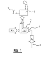
Figure 1 shows how Nitrogen for use in the method according to the invention is separated from oxygen in an Air Separation Unit(ASU); -
Figure 2A schematically shows how production of Natural Gas is enhanced by one embodiment of the Nitrogen Assisted Depletion Drive (NADD)method according to the invention; -
Figure 2B schematically shows how production of Natural Gas is enhanced by another embodiment of the Nitrogen Assisted Depletion Drive (NADD) in combination with the Nitrogen Enhanced Residual Gas (NERG) method according to the invention; -
Figure 2C schematically shows how production of Natural Gas is enhanced by a yet another embodiment of the combination of the Nitrogen Assisted Depletion Drive (NADD) and the Nitrogen Enhanced Residual Gas (NERG) method according to the invention; -
Figure 2D schematically shows how production of Natural Gas is enhanced by a further embodiment of the Nitrogen Enhanced Residual Gas (NERG) method according to the invention; and -
Figure 3 schematically shows how production of Natural Gas is enhanced in a tight gas reservoir by yet a further embodiment of either the Nitrogen Assisted Depletion Drive (NADD) or the Nitrogen Enhanced Residual Gas (NERG) method according to the invention. -
-
Figure 1 shows how Nitrogen (N2) is separated from oxygen (O2) in an Air Separation Unit (ASU)(1) of a power plant (2) that generates electrical energy (3) by combusting fuel using Oxygen(O2) or an Oxygen enriched air mixture. The generated Nitrogen (N2) is subsequently pumped by a compressor (4) into a nitrogen supply conduit (5) that is connected to one or moreNitrogen injections wells Figures 2A-D and 3 . -
Figures 2A-2D schematically show how Nitrogen (N2) that may be generated by the ASU (1) shown inFigure 1 is injected into anunderground gas reservoir 20 to perform a Nitrogen Assisted Depletion Drive (NADD) or the Nitrogen Enhanced Residual Gas (NERG) method according to the invention. - The
underground gas reservoir 20 is located in a permeable gas bearing formation layer, also known as the reservoir formation, which is located underneath an impermeablegas cap layer 21 and the Nitrogen (N2) is injected via a Nitrogen injection well 22 into a part of thereservoir formation 20 at a distance to the production well at 20A of thereservoir formation 20 whilst natural gas (comprising CH4 and other constituents) is produced via a naturalgas production well 23. - In the embodiment shown in
Figure 2A thereservoir formation 20 only comprises a minor fraction of water which is dispersed in the pores of thereservoir formation 20, so that there is no mobile water accumulation in this part of thereservoir formation 20. - In the embodiment shown in
Figure 2B there is significant accumulation of water (H2O) in the pores of near thelower edge 20A of thereservoir formation 20, so that there is awater layer 24 having aupper water level 25 within the pores of thereservoir formation 20, but which water layer may comprise a substantial amount of natural gas that is trapped as a discontinuous phase, i.e. as small bubbles, in the water. - In the embodiment shown in
Figure 2B the Nitrogen (N2) is injected into thewater layer 24 to stimulate migration of natural gas (CH4) from thewater layer 24 and to enhance flux of natural gas (CH4) through thereservoir formation 20 to the natural gas production well 23. -
Figure 2C schematically shows how natural gas (CH4) has been partly separated from the pores near thelower edge 20A of thereservoir formation 20 and pore water reaches the production well 23 leaving trapped or residual gas bubbles behind. -
Figure 2D schematically shows an embodiment where the pores of substantially theentire reservoir formation 20 are filled with a water-gas mixture comprising pore water and natural gas (CH4), which mixture is stimulated to flow into the production well 23 by injecting Nitrogen into the injection well 22 near the lower edge of thereservoir formation 20. -
Figure 3 schematically shows how production of Natural Gas (CH4) from a tight gas reservoir orresidual gas formation 30 is enhanced by yet another embodiment of the Nitrogen Assisted Depletion Drive (NADD) or Nitrogen Enhanced Residual Gas (NERG) process according to the invention wherein Nitrogen is injected into possibly severalNitrogen injection wells 31A-D and natural gas (CH4) is produced via possiblyseveral production wells 32A-D traversing thetight gas formation 30.
Claims (10)
- A method for enhancing natural gas production from an underground natural gas containing formation, the method comprising injecting into the formation a non-corrosive displacement gas comprising Nitrogen followed by injecting into the formation a corrosive displacement gas comprising Carbon Dioxide.
- The method of claim 1, wherein the non-corrosive displacement gas is injected into the formation as a slug which provides in the formation a barrier that inhibits mixing of the corrosive displacement gas with the natural gas and inhibits the corrosive displacement gas to reach corrosion prone natural gas production facilities.
- The method of claim 2, wherein after injecting the slug of the non corrosive displacement gas a slug of water is injected into the formation before injecting the corrosive displacement gas into the formation.
- The method of any one of claims 1-3, wherein the Nitrogen is generated in an Air Separation Unit(ASU) of a power or other industrial plant in which a mixture of fuel oxygen enriched air generated by the ASU is combusted to generate electrical energy and the Carbon Dioxide is obtained from flue gases of the plant.
- The method of any one of claims 1-4, wherein the non corrosive and corrosive displacement gases are each injected into the formation during a period of at least one month, during at least part of which period the natural gas is produced from the formation.
- The method of any one of claims 1-5, wherein the non corrosive and corrosive displacement gases are injected into the formation at a pressure below a fracturing pressure of the formation.
- The method of any one of claims 1, 2 and 4-6, wherein the formation comprises residual natural gas trapped in pore water below a Free Water Level (FWL) and the non corrosive and corrosive displacement gases are injected into the pore water below the Free Water Level (FWL) in the formation.
- The method of claim 6 or 7, wherein the formation is a tilted permeable formation layer with an upper and a lower edge and the non corrosive and corrosive displacement gases are injected into the formation in the vicinity of the lower edge of the tilted permeable underground formation layer.
- The method of any one of claim 1-8, wherein the formation does not contain a substantial amount of associated natural gas formed by natural gas associated to crude oil production, natural gas in a gas cap above an oil reservoir, crude oil and/or condensates.
- A system for enhancing natural gas production from an underground natural gas containing formation, the system comprising:- an injection well assembly configured to subsequently inject a non corrosive displacement gas comprising Nitrogen and a corrosive displacement gas comprising Carbon Dioxide into the formation during a period of at least one month;- a production well assembly configured to produce natural gas during at least part of said period; and- a power plant in which fuel is combusted with oxygen enriched air obtained from an Air Separation Unit(ASU)which is configured to generate the Nitrogen for use in the non corrosive displacement gas;- flue gas separation means connected to a flue gas exhaust assembly of the power plant for separating the Carbon Dioxide from flue gases of the power plant.
Priority Applications (1)
| Application Number | Priority Date | Filing Date | Title |
|---|---|---|---|
| EP12194473.0A EP2735697A1 (en) | 2012-11-27 | 2012-11-27 | Method and system for inhibiting contact of a corrosive displacement gas with corrosion prone natural gas production facilities |
Applications Claiming Priority (1)
| Application Number | Priority Date | Filing Date | Title |
|---|---|---|---|
| EP12194473.0A EP2735697A1 (en) | 2012-11-27 | 2012-11-27 | Method and system for inhibiting contact of a corrosive displacement gas with corrosion prone natural gas production facilities |
Publications (1)
| Publication Number | Publication Date |
|---|---|
| EP2735697A1 true EP2735697A1 (en) | 2014-05-28 |
Family
ID=47227686
Family Applications (1)
| Application Number | Title | Priority Date | Filing Date |
|---|---|---|---|
| EP12194473.0A Withdrawn EP2735697A1 (en) | 2012-11-27 | 2012-11-27 | Method and system for inhibiting contact of a corrosive displacement gas with corrosion prone natural gas production facilities |
Country Status (1)
| Country | Link |
|---|---|
| EP (1) | EP2735697A1 (en) |
Cited By (3)
| Publication number | Priority date | Publication date | Assignee | Title |
|---|---|---|---|---|
| NL2019056B1 (en) * | 2017-06-12 | 2018-12-19 | Circular Energy B V | Power plant, a gas field, a method of exploitation of a subsurface hydrocarbon reservoir. |
| EP3470621A1 (en) | 2019-01-02 | 2019-04-17 | L2 Consultancy B.V. | System and method for adjusting pressure in a subsurface reservoir and system for producing at least one gas for adjusting pressure in a subsurface reservoir |
| WO2020141153A1 (en) | 2019-01-02 | 2020-07-09 | L2 Consultancy B.V. | System and method for adjusting pressure in a reservoir and system for producing at least one energy carrier |
Citations (9)
| Publication number | Priority date | Publication date | Assignee | Title |
|---|---|---|---|---|
| US4393936A (en) * | 1981-09-21 | 1983-07-19 | Union Oil Company Of California | Method for the enhanced recovery of oil and natural gas |
| WO1987004420A1 (en) * | 1986-01-23 | 1987-07-30 | Kjelforeningen-Norsk Energi | Nitrogen injection |
| US4765407A (en) | 1986-08-28 | 1988-08-23 | Amoco Corporation | Method of producing gas condensate and other reservoirs |
| US5099921A (en) * | 1991-02-11 | 1992-03-31 | Amoco Corporation | Recovery of methane from solid carbonaceous subterranean formations |
| WO2003018958A1 (en) * | 2001-08-31 | 2003-03-06 | Statoil Asa | Method and plant for enhanced oil recovery and simultaneous synthesis of hydrocarbons from natural gas |
| CA2568358A1 (en) | 2006-11-17 | 2008-05-17 | James Q. Maguire | In-situ method of producing oil and gas (methane), on-shore and off-shore |
| WO2008087154A1 (en) * | 2007-01-19 | 2008-07-24 | L'air Liquide Societe Anonyme Pour L'etude Et L'exploitation Des Procedes Georges Claude | Process and apparatus for enhanced hydrocarbon recovery |
| US20110146978A1 (en) * | 2009-12-17 | 2011-06-23 | Greatpoint Energy, Inc. | Integrated enhanced oil recovery process |
| WO2012021282A1 (en) | 2010-08-09 | 2012-02-16 | Conocophillips Company | Method for enhanced gas hydrate permeability |
-
2012
- 2012-11-27 EP EP12194473.0A patent/EP2735697A1/en not_active Withdrawn
Patent Citations (9)
| Publication number | Priority date | Publication date | Assignee | Title |
|---|---|---|---|---|
| US4393936A (en) * | 1981-09-21 | 1983-07-19 | Union Oil Company Of California | Method for the enhanced recovery of oil and natural gas |
| WO1987004420A1 (en) * | 1986-01-23 | 1987-07-30 | Kjelforeningen-Norsk Energi | Nitrogen injection |
| US4765407A (en) | 1986-08-28 | 1988-08-23 | Amoco Corporation | Method of producing gas condensate and other reservoirs |
| US5099921A (en) * | 1991-02-11 | 1992-03-31 | Amoco Corporation | Recovery of methane from solid carbonaceous subterranean formations |
| WO2003018958A1 (en) * | 2001-08-31 | 2003-03-06 | Statoil Asa | Method and plant for enhanced oil recovery and simultaneous synthesis of hydrocarbons from natural gas |
| CA2568358A1 (en) | 2006-11-17 | 2008-05-17 | James Q. Maguire | In-situ method of producing oil and gas (methane), on-shore and off-shore |
| WO2008087154A1 (en) * | 2007-01-19 | 2008-07-24 | L'air Liquide Societe Anonyme Pour L'etude Et L'exploitation Des Procedes Georges Claude | Process and apparatus for enhanced hydrocarbon recovery |
| US20110146978A1 (en) * | 2009-12-17 | 2011-06-23 | Greatpoint Energy, Inc. | Integrated enhanced oil recovery process |
| WO2012021282A1 (en) | 2010-08-09 | 2012-02-16 | Conocophillips Company | Method for enhanced gas hydrate permeability |
Cited By (4)
| Publication number | Priority date | Publication date | Assignee | Title |
|---|---|---|---|---|
| NL2019056B1 (en) * | 2017-06-12 | 2018-12-19 | Circular Energy B V | Power plant, a gas field, a method of exploitation of a subsurface hydrocarbon reservoir. |
| EP3470621A1 (en) | 2019-01-02 | 2019-04-17 | L2 Consultancy B.V. | System and method for adjusting pressure in a subsurface reservoir and system for producing at least one gas for adjusting pressure in a subsurface reservoir |
| WO2020141153A1 (en) | 2019-01-02 | 2020-07-09 | L2 Consultancy B.V. | System and method for adjusting pressure in a reservoir and system for producing at least one energy carrier |
| NL2025903A (en) | 2019-01-02 | 2020-10-22 | L2 Consultancy B V | System and method for adjusting pressure in a reservoir and system for producing at least one energy carrier |
Similar Documents
| Publication | Publication Date | Title |
|---|---|---|
| US9453399B2 (en) | Method and apparatus for using pressure cycling and cold liquid CO2 for releasing natural gas from coal and shale formations | |
| EP2109584B1 (en) | Method for reducing the emission of green house gases into the atmosphere | |
| US7172030B2 (en) | Applications of waste gas injection into natural gas reservoirs | |
| EP2622174B1 (en) | Methods for storing carbon dioxide compositions in subterranean geological formations and an apparatus for carrying out the method | |
| US20210372235A1 (en) | System and method for permanent storage of carbon dioxide in shale reservoirs | |
| US20140041867A1 (en) | Enhanced oil recovery initiated with zero emission in-situ combustion | |
| US20160298425A1 (en) | System and Method for Permanent Storage of Carbon Dioxide in Shale Reservoirs | |
| CN106677745A (en) | Process method combining natural gas hydrate depressurizing development with CO2 storage | |
| US20150292303A1 (en) | Process for sequestration of fluids in geological formations | |
| US20110038670A1 (en) | Gaseous Sequestration Methods and Systems | |
| Burton et al. | Surface dissolution: minimizing groundwater impact and leakage risk simultaneously | |
| AU2011373946B2 (en) | Recovery methods for hydrocarbon gas reservoirs | |
| EP2726701B1 (en) | A method for storing carbon dioxide compositions in subterranean geological formations and an arrangement for use in such methods | |
| EP2735697A1 (en) | Method and system for inhibiting contact of a corrosive displacement gas with corrosion prone natural gas production facilities | |
| CN104533368A (en) | Application and system of in-situ combustion flue gas in oil reservoir exploitation | |
| EP3368738A1 (en) | System and method for permanent storage of carbon dioxide in shale reservoirs | |
| EP2735696A1 (en) | Method and system for enhancing natural gas production | |
| WO2015178899A1 (en) | Method and system for enhancing natural gas production | |
| JP6327730B2 (en) | Mining method for water-soluble natural gas | |
| JP5133785B2 (en) | Natural gas ground seepage control system | |
| EP2735698A1 (en) | Enhancing natural gas production using nitrogen generated by an air separation unit of an industrial plant | |
| WO2015178898A1 (en) | Method and system for enhancing natural gas production | |
| WO2022176847A1 (en) | Method for underground storage of pressurized gas including co2 gas, and enhanced oil recovery | |
| CN113236204B (en) | Surface active graphene and industrial flue gas foam water control oil gas displacement method and system | |
| RU2393344C1 (en) | Disposal method of technogenic carbon dioxide of flue gas |
Legal Events
| Date | Code | Title | Description |
|---|---|---|---|
| PUAI | Public reference made under article 153(3) epc to a published international application that has entered the european phase |
Free format text: ORIGINAL CODE: 0009012 |
|
| 17P | Request for examination filed |
Effective date: 20121127 |
|
| AK | Designated contracting states |
Kind code of ref document: A1 Designated state(s): AL AT BE BG CH CY CZ DE DK EE ES FI FR GB GR HR HU IE IS IT LI LT LU LV MC MK MT NL NO PL PT RO RS SE SI SK SM TR |
|
| AX | Request for extension of the european patent |
Extension state: BA ME |
|
| STAA | Information on the status of an ep patent application or granted ep patent |
Free format text: STATUS: THE APPLICATION IS DEEMED TO BE WITHDRAWN |
|
| 18D | Application deemed to be withdrawn |
Effective date: 20141129 |