EP2735500A1 - Inverted mobile body control device, and method and program therefor - Google Patents
Inverted mobile body control device, and method and program therefor Download PDFInfo
- Publication number
- EP2735500A1 EP2735500A1 EP11869837.2A EP11869837A EP2735500A1 EP 2735500 A1 EP2735500 A1 EP 2735500A1 EP 11869837 A EP11869837 A EP 11869837A EP 2735500 A1 EP2735500 A1 EP 2735500A1
- Authority
- EP
- European Patent Office
- Prior art keywords
- driving wheel
- wheel
- skid
- inverted vehicle
- driving
- Prior art date
- Legal status (The legal status is an assumption and is not a legal conclusion. Google has not performed a legal analysis and makes no representation as to the accuracy of the status listed.)
- Granted
Links
Images


Classifications
-
- B—PERFORMING OPERATIONS; TRANSPORTING
- B60—VEHICLES IN GENERAL
- B60L—PROPULSION OF ELECTRICALLY-PROPELLED VEHICLES; SUPPLYING ELECTRIC POWER FOR AUXILIARY EQUIPMENT OF ELECTRICALLY-PROPELLED VEHICLES; ELECTRODYNAMIC BRAKE SYSTEMS FOR VEHICLES IN GENERAL; MAGNETIC SUSPENSION OR LEVITATION FOR VEHICLES; MONITORING OPERATING VARIABLES OF ELECTRICALLY-PROPELLED VEHICLES; ELECTRIC SAFETY DEVICES FOR ELECTRICALLY-PROPELLED VEHICLES
- B60L15/00—Methods, circuits, or devices for controlling the traction-motor speed of electrically-propelled vehicles
- B60L15/20—Methods, circuits, or devices for controlling the traction-motor speed of electrically-propelled vehicles for control of the vehicle or its driving motor to achieve a desired performance, e.g. speed, torque, programmed variation of speed
-
- B—PERFORMING OPERATIONS; TRANSPORTING
- B62—LAND VEHICLES FOR TRAVELLING OTHERWISE THAN ON RAILS
- B62K—CYCLES; CYCLE FRAMES; CYCLE STEERING DEVICES; RIDER-OPERATED TERMINAL CONTROLS SPECIALLY ADAPTED FOR CYCLES; CYCLE AXLE SUSPENSIONS; CYCLE SIDECARS, FORECARS, OR THE LIKE
- B62K11/00—Motorcycles, engine-assisted cycles or motor scooters with one or two wheels
- B62K11/007—Automatic balancing machines with single main ground engaging wheel or coaxial wheels supporting a rider
-
- B—PERFORMING OPERATIONS; TRANSPORTING
- B60—VEHICLES IN GENERAL
- B60L—PROPULSION OF ELECTRICALLY-PROPELLED VEHICLES; SUPPLYING ELECTRIC POWER FOR AUXILIARY EQUIPMENT OF ELECTRICALLY-PROPELLED VEHICLES; ELECTRODYNAMIC BRAKE SYSTEMS FOR VEHICLES IN GENERAL; MAGNETIC SUSPENSION OR LEVITATION FOR VEHICLES; MONITORING OPERATING VARIABLES OF ELECTRICALLY-PROPELLED VEHICLES; ELECTRIC SAFETY DEVICES FOR ELECTRICALLY-PROPELLED VEHICLES
- B60L15/00—Methods, circuits, or devices for controlling the traction-motor speed of electrically-propelled vehicles
- B60L15/02—Methods, circuits, or devices for controlling the traction-motor speed of electrically-propelled vehicles characterised by the form of the current used in the control circuit
- B60L15/08—Methods, circuits, or devices for controlling the traction-motor speed of electrically-propelled vehicles characterised by the form of the current used in the control circuit using pulses
-
- B—PERFORMING OPERATIONS; TRANSPORTING
- B60—VEHICLES IN GENERAL
- B60L—PROPULSION OF ELECTRICALLY-PROPELLED VEHICLES; SUPPLYING ELECTRIC POWER FOR AUXILIARY EQUIPMENT OF ELECTRICALLY-PROPELLED VEHICLES; ELECTRODYNAMIC BRAKE SYSTEMS FOR VEHICLES IN GENERAL; MAGNETIC SUSPENSION OR LEVITATION FOR VEHICLES; MONITORING OPERATING VARIABLES OF ELECTRICALLY-PROPELLED VEHICLES; ELECTRIC SAFETY DEVICES FOR ELECTRICALLY-PROPELLED VEHICLES
- B60L2200/00—Type of vehicles
- B60L2200/14—Vehicles with one wheel only
-
- B—PERFORMING OPERATIONS; TRANSPORTING
- B60—VEHICLES IN GENERAL
- B60L—PROPULSION OF ELECTRICALLY-PROPELLED VEHICLES; SUPPLYING ELECTRIC POWER FOR AUXILIARY EQUIPMENT OF ELECTRICALLY-PROPELLED VEHICLES; ELECTRODYNAMIC BRAKE SYSTEMS FOR VEHICLES IN GENERAL; MAGNETIC SUSPENSION OR LEVITATION FOR VEHICLES; MONITORING OPERATING VARIABLES OF ELECTRICALLY-PROPELLED VEHICLES; ELECTRIC SAFETY DEVICES FOR ELECTRICALLY-PROPELLED VEHICLES
- B60L2200/00—Type of vehicles
- B60L2200/16—Single-axle vehicles
-
- B—PERFORMING OPERATIONS; TRANSPORTING
- B60—VEHICLES IN GENERAL
- B60L—PROPULSION OF ELECTRICALLY-PROPELLED VEHICLES; SUPPLYING ELECTRIC POWER FOR AUXILIARY EQUIPMENT OF ELECTRICALLY-PROPELLED VEHICLES; ELECTRODYNAMIC BRAKE SYSTEMS FOR VEHICLES IN GENERAL; MAGNETIC SUSPENSION OR LEVITATION FOR VEHICLES; MONITORING OPERATING VARIABLES OF ELECTRICALLY-PROPELLED VEHICLES; ELECTRIC SAFETY DEVICES FOR ELECTRICALLY-PROPELLED VEHICLES
- B60L2260/00—Operating Modes
- B60L2260/20—Drive modes; Transition between modes
- B60L2260/34—Stabilising upright position of vehicles, e.g. of single axle vehicles
-
- Y—GENERAL TAGGING OF NEW TECHNOLOGICAL DEVELOPMENTS; GENERAL TAGGING OF CROSS-SECTIONAL TECHNOLOGIES SPANNING OVER SEVERAL SECTIONS OF THE IPC; TECHNICAL SUBJECTS COVERED BY FORMER USPC CROSS-REFERENCE ART COLLECTIONS [XRACs] AND DIGESTS
- Y02—TECHNOLOGIES OR APPLICATIONS FOR MITIGATION OR ADAPTATION AGAINST CLIMATE CHANGE
- Y02T—CLIMATE CHANGE MITIGATION TECHNOLOGIES RELATED TO TRANSPORTATION
- Y02T10/00—Road transport of goods or passengers
- Y02T10/60—Other road transportation technologies with climate change mitigation effect
- Y02T10/64—Electric machine technologies in electromobility
-
- Y—GENERAL TAGGING OF NEW TECHNOLOGICAL DEVELOPMENTS; GENERAL TAGGING OF CROSS-SECTIONAL TECHNOLOGIES SPANNING OVER SEVERAL SECTIONS OF THE IPC; TECHNICAL SUBJECTS COVERED BY FORMER USPC CROSS-REFERENCE ART COLLECTIONS [XRACs] AND DIGESTS
- Y02—TECHNOLOGIES OR APPLICATIONS FOR MITIGATION OR ADAPTATION AGAINST CLIMATE CHANGE
- Y02T—CLIMATE CHANGE MITIGATION TECHNOLOGIES RELATED TO TRANSPORTATION
- Y02T10/00—Road transport of goods or passengers
- Y02T10/60—Other road transportation technologies with climate change mitigation effect
- Y02T10/72—Electric energy management in electromobility
Definitions
- the present invention relates to an inverted vehicle control apparatus that controls an inverted vehicle, and a method and a program therefor.
- An inverted vehicle on which a rider rides and which performs desired traveling while maintaining the inverted state, has been known.
- a safety issue that arises, for example, when the inverted vehicle travels on a low-friction road surface such as a puddle, poses a problem.
- Patent literature 1 Japanese Patent No. 4162995
- the inverted vehicle control apparatus simply reduces the torque of the driving wheel(s). Therefore, if the amount of the skid of the driving wheel(s) is large during the traveling on the low-friction road surface, the inverted vehicle control apparatus cannot maintain the traveling safely or stop the inverted vehicle safely.
- the present invention has been made to solve the above problem , and a principal object thereof is to provide an inverted vehicle control apparatus, and its control method and program, capable of making an inverted vehicle travel safely or stop safely even on a low-friction road surface.
- one aspect of the present invention is an inverted vehicle control apparatus including: a plurality of driving wheels provided in an inverted vehicle; a plurality of drive means each of which drives a respective one of the plurality of driving wheels; skid detection means for detecting a skid state between the plurality of driving wheels and a road surface; operation information acquisition means for acquiring operation information of a rider; and control means for controlling driving of the drive means and thereby controlling the plurality of driving wheels, in which the control means controls, based on the operation information acquired by the operation information acquisition means, the driving wheel for which no skid is detected by the skid detection means, and the control means controls the driving wheel for which a skid is detected by the skid detection means so that a friction reaction force exerted from the road surface to the driving wheel is exerted in such a direction that the inverted vehicle is raised by the friction reaction force.
- this one aspect it is possible to make the inverted vehicle travel safely or stop safely even on a low-friction road surface.
- the inverted vehicle control apparatus may further include: pitch angle detection means for detecting a pitch angle of the inverted vehicle; and wheel horizontal speed calculation means for calculating a horizontal speed of the driving wheel of the inverted vehicle, in which the control means may control the driving wheel for which the skid is detected by the skid detection means, based on the pitch angle of the inverted vehicle detected by the pitch angle detection means and the horizontal speed of the driving wheel calculated by the wheel horizontal speed calculation means.
- control means may include: wheel angular speed reference input calculation means for calculating an angular speed reference input of the driving wheel based on operation information acquired by the operation information acquisition means, a horizontal moving speed of the driving wheel calculated by the wheel horizontal speed calculation means, and skid information of the driving wheel detected by the skid detection means; and safety control means for maintaining an inverted state of the inverted vehicle by controlling the driving of the drive means based on the angular speed reference input of the driving wheel calculated by the wheel angular speed reference input calculation means.
- the wheel angular speed reference input calculation means may calculate the angular speed reference input for the driving wheel for which the skid is detected by the skid detection means, by using an expression shown below.
- the operation information acquisition means may include traveling direction speed input means for outputting a traveling direction and a traveling speed of the inverted vehicle based on the operation information entered by the rider.
- the inverted vehicle control apparatus may further include: wheel angular speed detection means for detecting an angular speed of the driving wheel; yaw angle detection means for detecting a yaw angle of the inverted vehicle; and wheel horizontal acceleration calculation means for calculating a horizontal acceleration of the driving wheel based on the angular speed of the driving wheel detected by the wheel angular speed detection means, the pitch angle of the inverted vehicle detected by the pitch angle detection means, the yaw angle of the inverted vehicle detected by the yaw angle detection means, and a control signal for controlling the drive means.
- the skid detection means may include skid parameter calculation means for calculating a skid parameter indicating whether the driving wheel is skidding or not, based on the angular speed of the driving wheel detected by the wheel angular speed detection means and the horizontal acceleration of the driving wheel calculated by the wheel horizontal acceleration calculation means, and outputting the calculated skid parameter to the control means.
- the wheel horizontal acceleration calculation means may calculate a horizontal acceleration of the first and second driving wheels by using an expression shown below.
- the safety control means may calculate a driving torque T for the skidding driving wheel by using an expression shown below.
- another aspect of the present invention may be a control method for an inverted vehicle control apparatus, including: a step of detecting a skid state between a plurality of driving wheels provided in an inverted vehicle and a road surface; a step of acquiring operation information of a rider; and a step of controlling, based on the acquired operation information, the driving wheel for which no skid is detected, and controlling the driving wheel for which a skid is detected so that a friction reaction force exerted from the road surface to the driving wheel is exerted in such a direction that the inverted vehicle is raised by the friction reaction force.
- another aspect of the present invention may be a program for an inverted vehicle control apparatus for causing a computer to execute: a process of detecting a skid state between a plurality of driving wheels provided in an inverted vehicle and a road surface; and a process of controlling, based on operation information of a rider, the driving wheel for which no skid is detected, and controlling the driving wheel for which a skid is detected so that a friction reaction force exerted from the road surface to the driving wheel is exerted in such a direction that the inverted vehicle is raised by the friction reaction force.
- an inverted vehicle control apparatus and its control method and program, capable of making an inverted vehicle travel safely or stop safely even on a low-friction road surface.
- An inverted vehicle control apparatus 100 is an apparatus that controls the traveling of an inverted vehicle 110 as shown in Fig. 4 .
- the inverted vehicle 110 according to this exemplary embodiment includes a platform 401 on which a rider rides, a pair of first and second driving wheels 402 rotatably disposed on both sides of the platform 401, a handlebar 403 which is swingably disposed in the platform 401 and which the rider grasps and operates, and a control mechanism 111 disposed inside the platform 401.
- the inverted vehicle 110 performs desired traveling while maintaining the inverted state according to a traveling operation by the rider.
- Fig. 1 is a block diagram showing a schematic system configuration of an inverted vehicle control apparatus according to this exemplary embodiment.
- the inverted vehicle control apparatus 100 includes the control mechanism 111, a traveling direction speed input device 112 that detects the operation state of the handlebar 403 by the rider, a pair of first and second motors 113 that drive the first and second driving wheels 402, a wheel angular speed detector 114 that detects angular speeds of the first and second driving wheels 402, a pitch angle detector 115 that detects the pitch angle of the platform 401, a yaw angle detector 116 that detects the yaw angle of the platform 401, and a control device 120 that controls the driving of each of the first and second motors 113.
- the traveling direction speed input device 112 is a specific example of the traveling direction speed input means and is disposed in the handlebar 403.
- the traveling direction speed input device 112 detects the tilt angle of that handlebar 403, calculates the traveling direction and the moving speed of the inverted vehicle 110 according to that tilt angle, and outputs the calculated direction and speed to the control device 120 as traveling direction speed information.
- the first and second motors 113 are a specific example of the drive means, and are disposed inside the platform 401 and connected to the drive shaft(s) of the first and second driving wheels 402 through a speed reducer or the like.
- the first and second motors 113 rotationally drive the first and second driving wheels 402 independently of each other according to a control signal(s) from the control device 120, and thereby make the inverted vehicle 110 travel in a desired direction at a desired speed while maintaining the inverted state of the inverted vehicle 110.
- the wheel angular speed detector 114 is a specific example of the wheel angular speed detection means and is disposed in the drive shaft of the first and second driving wheels 402 or the like.
- the wheel angular speed detector 114 detects the angular speeds of the first and second driving wheels 402 and outputs the detected angular speeds to the control device 120 as measured wheel angular speeds.
- the pitch angle detector 115 is a specific example of the pitch angle detection means and is disposed in the platform 401.
- the pitch angle detector 115 detects the pitch angle of the platform 401 and outputs the detected pitch angle to the control device 120 as a measured pitch angle.
- the yaw angle detector 116 is a specific example of the yaw angle detection means and is disposed in the platform 401.
- the yaw angle detector 116 detects the yaw angle of the platform 401 and outputs the detected yaw angle to the control device 120 as a measured yaw angle.
- the control device 120 includes a wheel angular speed reference input calculator 121, a safety controller 122, a wheel horizontal acceleration calculator 123, a skid parameter calculator 124, and a wheel horizontal speed calculator 125.
- control device 120 is composed of, for example, hardware including a microcomputer as a principal component.
- the microcomputer includes, for example, a CPU (Central Processing Unit) that performs arithmetic processing, control processing, and the like, a ROM (Read Only Memory) that stores an arithmetic program, a control processing program, and the like that are executed by the CPU, and a RAM (Random Access Memory) that temporarily stores processing data and the like.
- the CPU, the ROM, and the RAM are connected with one another through a data bus or the like.
- the wheel horizontal acceleration calculator 123 is a specific example of the wheel horizontal acceleration calculation means.
- the wheel horizontal acceleration calculator 123 calculates a wheel horizontal acceleration(s) indicating the horizontal acceleration(s) of the first and second driving wheels 402 based on the measured wheel angular speed from the wheel angular speed detector 114, the measured pitch angle from the pitch angle detector 115, measured yaw angle from the yaw angle detector 116, and a motor current(s) (control signal(s)) output from the safety controller 122 to the first and second motors 113, and outputs the calculated wheel horizontal acceleration(s) to the skid parameter calculator 124 and the wheel horizontal speed calculator 125.
- the skid parameter calculator 124 is a specific example of the skid parameter calculation means.
- the skid parameter calculator 124 calculates first and second skid parameters indicating the skid states of the first and second driving wheels 402 based on the wheel horizontal acceleration from the wheel horizontal acceleration calculator 123 and the measured wheel angular speed from the wheel angular speed detector 114, and outputs the calculated first and second skid parameters to the wheel angular speed reference input calculator 121.
- the wheel horizontal speed calculator 125 is a specific example of the wheel horizontal speed calculation means.
- the wheel horizontal speed calculator 125 performs integration processing for the wheel horizontal acceleration from the wheel horizontal acceleration calculator 123, calculates wheel horizontal speeds indicating the horizontal speeds of the first and second driving wheels 402, and outputs the calculated wheel horizontal speeds to the wheel angular speed reference input calculator 121.
- the wheel angular speed reference input calculator 121 is a specific example of the wheel angular speed reference input calculation means.
- the wheel angular speed reference input calculator 121 calculates first and second wheel angular speed reference inputs for the first and second driving wheels 402 for making the inverted vehicle 110 travel safely or stop safely, based on the traveling direction speed information from the traveling direction speed input device 112, the wheel horizontal speed from the wheel horizontal speed calculator 125, the first and second skid parameters from the skid parameter calculator 124, and the measured pitch angle from the pitch angle detector 115, and outputs the calculated first and second wheel angular speed reference inputs to the safety controller 122.
- the safety controller 122 is a specific example of the safety control means.
- the safety controller 122 calculates such motor currents that the safest motor torques are generated according to the skid states between the first and second driving wheels 402 and the road surface, based on the first and second wheel angular speed reference inputs from the wheel angular speed reference input calculator 121, and outputs the calculated motor currents to the first and second motors 113.
- the safety controller 122 controls, based on operation information entered by the rider, the first or second driving wheel 402 for which no skid is detected, and controls the first or second driving wheel 402 for which a skid is detected so that the friction reaction force exerted from the road surface to the first or second driving wheel 402 is exerted in such a direction that the inverted vehicle 110 is raised by the friction reaction force.
- the inverted state of the inverted vehicle 110 can be maintained as much as possible. Further, even if the inverted state cannot be maintained, the falling-down impact can be minimized, thus allowing the rider to get off the inverted vehicle safely.
- each symbol is defined as follows.
- m w the mass [kg] of the first and second driving wheels 402
- x 1 a first wheel horizontal position [m] (horizontal position of the first driving wheel 402)
- x 2 a second wheel horizontal position [m] (horizontal position of the second driving wheel 402)
- H g1 a horizontal reaction force (friction reaction force) [N] exerted from the road surface to the first driving wheel 402
- H g2 a horizontal reaction force (friction reaction force) [N] exerted from the road surface to the second driving wheel 402
- H c1 a horizontal reaction force [N] exerted from the chassis 404 (integrally composed of the platform 401, handlebar 403, and rider) to the first driving wheel 402
- H e2 a horizontal reaction force [N] exerted from the chassis 404 to the second driving wheel 402
- V g1 a vertical reaction force [N] exerted from
- Expression (12) shown below can be obtained based on the above-shown Expressions (1), (3), (4), (6), (7) and (10).
- m w + m c 2 ⁇ r w ⁇ x ⁇ 1 + m w + m c 2 ⁇ r w ⁇ x ⁇ 2 - m c ⁇ r w ⁇ l ⁇ sin ⁇ p ⁇ ⁇ ⁇ p 2 + m c ⁇ r w ⁇ l ⁇ cos ⁇ p ⁇ ⁇ ⁇ p + J w ⁇ ⁇ ⁇ 1 + J w ⁇ ⁇ ⁇ 2 T 1 + T 2
- the first wheel horizontal acceleration (horizontal acceleration of the first driving wheel) d 2 x 1 /dt 2 and the second wheel horizontal acceleration (horizontal acceleration of the second driving wheel) d 2 x 2 /dt 2 can be expressed as Expressions (15) and (16) shown below.
- x ⁇ 1 m c ⁇ l m w + m c 2 ⁇ sin ⁇ p ⁇ ⁇ ⁇ p 2 - m c ⁇ l m w + m c 2 ⁇ cos ⁇ p ⁇ ⁇ ⁇ p - J w m w + m c 2 ⁇ r w ⁇ ⁇ ⁇ 1 - J w m w + m c 2 ⁇ r w ⁇ ⁇ ⁇ 2 + 1 m w + m c 2 ⁇ r w ⁇ ⁇ 2 + 1 m w + m c 2 ⁇ r w ⁇ T 1 + 1 m w + m c 2 ⁇ r w ⁇ T 2 - 2 ⁇ d ⁇ sec 2 ⁇ ⁇ y ⁇ tan ⁇ y ⁇ ⁇ ⁇ y 2 + d m w + m c 2 ⁇ r w ⁇ sec 2
- the wheel horizontal acceleration calculator 123 calculates the first and second horizontal accelerations by using the above-shown Expressions (15) and (16), and outputs the calculated first and second horizontal accelerations to the wheel horizontal speed calculator 125.
- the skid parameter calculator 124 respectively calculates a first skid parameter s 1 indicating the skid state between the first driving wheel 402 and road surface and a second skid parameter s 2 indicating the skid state between the second driving wheel 402 and road surface by using the above-shown Expressions (17) and (18), and outputs the calculated first and second skid parameters s 1 and s 2 to the wheel angular speed reference input calculator 121.
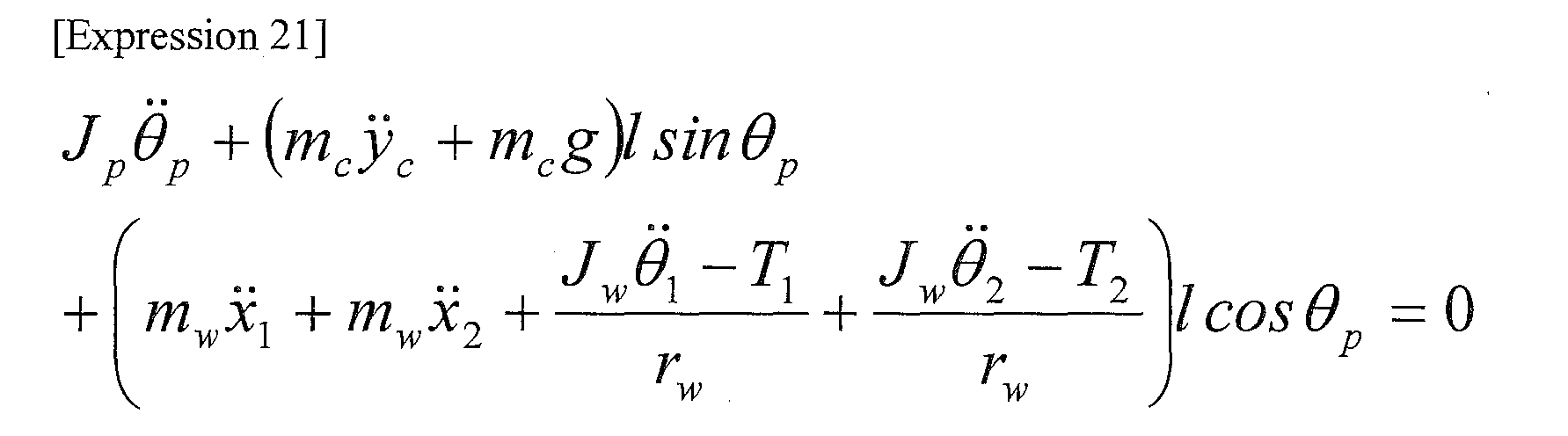
- Expression (21) shown below can be obtained by using the above-shown Expressions (3), (6), (19) and (20).
- J p ⁇ ⁇ ⁇ p + m w ⁇ y ⁇ c + m c ⁇ g ⁇ l sin ⁇ ⁇ p + m w ⁇ x ⁇ 1 + m w ⁇ x ⁇ 2 + J w ⁇ ⁇ ⁇ 1 - T 1 r w + J w ⁇ ⁇ ⁇ 1 - T 1 r w ⁇ l cos ⁇ ⁇ p 0
- the wheel angular speed reference input calculator 121 respectively calculates a first wheel angular speed reference input for the first driving wheel 402 and a second wheel angular speed reference input for the second driving wheel 402 based on the traveling direction speed information from the traveling direction speed input device 112, the wheel horizontal speed from the wheel horizontal speed calculator 125, and the first and second skid parameters from the skid parameter calculator 124, and outputs the calculated first and second wheel angular speed reference inputs to the safety controller 122.
- the wheel angular speed reference input calculator 121 calculates a first wheel angular speed reference input according to the traveling direction and the moving speed of the inverted vehicle 110 provided from the traveling direction speed input device 112 and outputs the calculated first wheel angular speed reference input to the safety controller 122.
- the wheel angular speed reference input calculator 121 calculates a first wheel angular speed reference input expressed by Expression (24) shown below and outputs the calculated first wheel angular speed reference input to the safety controller 122.
- Expression (24) the symbol ⁇ represents a small parameter [rad/s] of the wheel angular speed reference input.
- the inverted vehicle 110 when the inverted vehicle 110 is moving forward in a forward-bent posture, it is possible to produce the maximum value of the friction reaction force exerted from the road surface in such a direction that the inverted vehicle 110 is raised by the friction reaction force by rotating the skidding first and second driving wheels 402 slightly faster than the traveling speed of the inverted vehicle 110. As a result, it is possible to maintain the inverted state of the inverted vehicle 110 as much as possible. Further, when the inverted vehicle 110 is moving forward in a backward-bent posture, it is possible to produce the maximum value of the friction reaction force exerted from the road surface in such a direction that the inverted vehicle 110 is raised by the friction reaction force by rotating the skidding first and second driving wheels 402 slightly slower than the traveling speed of the inverted vehicle 110.
- Expression (25) shown below
- the first wheel angle ⁇ 1 which is the rotation angle of the first driving wheel 402, can be made to converge at the first wheel angle reference input ⁇ 1r .
- the safety controller 122 calculates the first motor torque T 1 based on the first wheel angular speed reference input expressed by the above-shown Expression (24) provided from the wheel angular speed reference input calculator 121 by using the above-shown Expression (29).
- the safety controller 122 can bring the friction between the first driving wheel 402 that has just started skidding and the road surface close to the maximum static friction by outputting a motor current corresponding to the calculated first motor torque T 1 , and thereby prevent the skidding speed of the first driving wheel 402 from increasing.
- the safety controller 122 calculates the second motor torque T 2 based on the second wheel angular speed reference input expressed by the above-shown Expression (25) provided from the wheel angular speed reference input calculator 121 by using Expression (30) shown below.
- Expression (30) shown below.
- the symbol ⁇ 2 represents the degree of convergence [rad/s] of the second wheel angle deviation
- the symbol M 2 represents the amplitude [N ⁇ m] of the second motor torque T 2 when the second driving wheel 402 is skidding.
- a first motor torque T 1 for controlling the pitch angle of the platform 401 is calculated.
- a variable shown in the below-shown Expression (32) and a candidate for a Liapunov function shown in the below-shown Expression (33) are introduced.
- the symbol ⁇ p represents the degree of convergence [rad/s] of the pitch angle deviation.
- T 1 - M p ⁇ 1 ⁇ sgn q p M p ⁇ 1 > - r w ⁇ m c ⁇ lcos ⁇ p ⁇ ⁇ ⁇ p 2 - r w ⁇ m c ⁇ lsin ⁇ p ⁇ ⁇ ⁇ p 2 + r w ⁇ m c ⁇ g +
- the inverted vehicle control apparatus 100 stops the inversion control (safe torque-off).
- the safety controller 122 controls the first motor 113 based on the first motor torque T 1 expressed by the above-shown Expression (35). As a result, it is possible to maintain the inverted state of the inverted vehicle 110 while making the pitch angle ⁇ p of the platform 401 converge at zero.
- the safety controller 122 controls the second motor 113 based on the second motor torque T 2 expressed by Expression (37) shown below.
- Expression (37) shown below.
- the symbol Mp2 represents the amplitude [N ⁇ m] of the second motor torque T 2 when the second driving wheel 402 is not skidding.
- T 2 - M p ⁇ 2 ⁇ sgn q p M p ⁇ 2 > - r w ⁇ m c ⁇ lcos ⁇ p ⁇ ⁇ ⁇ p 2 - r w ⁇ m c ⁇ lsin ⁇ p ⁇ ⁇ ⁇ p 2 + r w ⁇ m c ⁇ g +
- each parameter is set as shown below in this simulation.
- the symbol ng represents a reduction ratio and the symbol T represents a control cycle.
- m c 70 kg
- J p 25.2 kg ⁇ m 2
- m w 15 kg
- J w 0.075 kg ⁇ m 2
- 1 0.9 m
- r w 0.1 m
- d 0.3 m
- g 9.8 m / s 2
- n g 100
- ⁇ p 10 ⁇ 2 ⁇ ⁇ rad / s
- T 1 ⁇ 10 - 3 s
- Fig. 2 is a graph showing a simulation result of the inverted vehicle control apparatus 100 according to this exemplary embodiment, and shows temporal changes of the pitch angle of the platform.
- the solid line (1) represents pitch angles ⁇ p obtained by the inverted vehicle control apparatus 100 according to this exemplary embodiment
- the broken line (2) represents pitch angles obtained by an inverted vehicle control apparatus in related art.
- the related-art inverted vehicle control apparatus performs a sliding mode control that is designed under the assumption that both the first and second driving wheels are not skidding.
- the rider inclines backward at a pitch angle of 0.1[rad] or larger when the rider tries to maintain the inverted state of the inverted vehicle. Further, in this simulation, since the rider and the chassis are modeled as one integrated rigid body, the inverted state can be maintained at a time 0.2[s]. However, there is a possibility that a real rider will react to the backward inclination of the inverted vehicle and, after that, fall down backward when the rider inclines the inverted vehicle forward.
- the inverted vehicle hardly inclines backward and thus the inverted state of the inverted vehicle 110 can be safely maintained.
- Fig. 3 is a graph showing a simulation result of the inverted vehicle control apparatus according to this exemplary embodiment, and shows temporal changes of the first motor torque.
- the solid line (3) represents first motor torques obtained by the inverted vehicle control apparatus 100 according to this exemplary embodiment
- the broken line (4) represents first motor torques obtained by the related-art inverted vehicle control apparatus.
- the sign of its first motor torque changes at an interval of 0.7[s] or larger.
- the sign of its first motor torque T 1 changes at small intervals at and after a time 0.1[s].
- the inverted state can be maintained by using the non-skidding driving wheel 402 alone without widely inclining the inverted vehicle 110 backward. Therefore, it is possible to safely control the inverted vehicle 110 without feeling any anxiety.
- the inverted vehicle control apparatus 100 controls, based on operation information entered by the rider, the first or second driving wheel 402 for which no skid is detected, and controls the first or second driving wheel 402 for which a skid is detected so that the friction reaction force exerted from the road surface to the first or second driving wheel 402 is exerted in such a direction that the inverted vehicle 110 is raised by the friction reaction force.
- the inverted state of the inverted vehicle 110 can be maintained as much as possible. Further, even if the inverted state cannot be maintained, the falling-down impact can be minimized, thus allowing the rider to get off the inverted vehicle safely. That is, it is possible to make the inverted vehicle 110 travel safely or stop safely even on a low-friction road surface.
- the present invention is not limited to the above-described exemplary embodiments, and those exemplary embodiments can be modified as appropriate without departing from the spirit and scope of the present invention.
- the present invention is applied to the inverted vehicle 110 including a pair of first and second driving wheels 402 in the above-described exemplary embodiment, the present invention is not limited to such inverted vehicles. That is, the present invention can be applied to an inverted vehicle including three or more driving wheels or an inverted vehicle including a coupled driving wheel(s).
- the present invention is not limited to such examples.
- the present invention can be applied to a case where there is an arbitrary disturbance such as when a head wind is blowing and when the inverted vehicle comes into contact with a nearby person, an object, or the like.
- control device 120 can be implemented by causing a CPU to execute a computer program.
- the above-described program can be stored in various types of non-transitory computer readable media and thereby supplied to computers.
- the non-transitory computer readable media includes various types of tangible storage media. Examples of the non-transitory computer readable media include a magnetic recording medium (such as a flexible disk, a magnetic tape, and a hard disk drive), a magneto-optic recording medium (such as a magneto-optic disk), a CD-ROM (Read Only Memory), a CD-R, and a CD-R/W, and a semiconductor memory (such as a mask ROM, a PROM (Programmable ROM), an EPROM (Erasable PROM), a flash ROM, and a RAM (Random Access Memory)).
- a magnetic recording medium such as a flexible disk, a magnetic tape, and a hard disk drive
- a magneto-optic recording medium such as a magneto-optic disk
- CD-ROM Read Only Memory
- CD-R Compact Only Memory
- the program can be supplied to computers by using various types of transitory computer readable media.
- Examples of the transitory computer readable media include an electrical signal, an optical signal, and an electromagnetic wave.
- the transitory computer readable media can be used to supply programs to a computer through a wire communication path such as an electrical wire and an optical fiber, or wireless communication path.
- the present invention can be applied to an inverted vehicle control apparatus that can make an inverted vehicle travel safely even on a low-friction road surface by controlling a plurality of driving wheels.
Landscapes
- Engineering & Computer Science (AREA)
- Mechanical Engineering (AREA)
- Power Engineering (AREA)
- Transportation (AREA)
- Motorcycle And Bicycle Frame (AREA)
- Electric Propulsion And Braking For Vehicles (AREA)
Abstract
Description
- The present invention relates to an inverted vehicle control apparatus that controls an inverted vehicle, and a method and a program therefor.
- An inverted vehicle, on which a rider rides and which performs desired traveling while maintaining the inverted state, has been known. In such an inverted vehicle, a safety issue that arises, for example, when the inverted vehicle travels on a low-friction road surface such as a puddle, poses a problem.
- To cope with this, an inverted vehicle control apparatus that, when it is determined that a driving wheel(s) has started to skid on the road surface, reduces the driving torque provided to each drive wheel until the skid of the skidding drive wheel stops has been known (see Patent literature 1).
- Patent literature 1: Japanese Patent No.
4162995 - However, in the above-described inverted vehicle control apparatus disclosed in
Patent literature 1, the inverted vehicle control apparatus simply reduces the torque of the driving wheel(s). Therefore, if the amount of the skid of the driving wheel(s) is large during the traveling on the low-friction road surface, the inverted vehicle control apparatus cannot maintain the traveling safely or stop the inverted vehicle safely. - The present invention has been made to solve the above problem , and a principal object thereof is to provide an inverted vehicle control apparatus, and its control method and program, capable of making an inverted vehicle travel safely or stop safely even on a low-friction road surface.
- To achieve the above-described object, one aspect of the present invention is an inverted vehicle control apparatus including: a plurality of driving wheels provided in an inverted vehicle; a plurality of drive means each of which drives a respective one of the plurality of driving wheels; skid detection means for detecting a skid state between the plurality of driving wheels and a road surface; operation information acquisition means for acquiring operation information of a rider; and control means for controlling driving of the drive means and thereby controlling the plurality of driving wheels, in which the control means controls, based on the operation information acquired by the operation information acquisition means, the driving wheel for which no skid is detected by the skid detection means, and the control means controls the driving wheel for which a skid is detected by the skid detection means so that a friction reaction force exerted from the road surface to the driving wheel is exerted in such a direction that the inverted vehicle is raised by the friction reaction force. According to this one aspect, it is possible to make the inverted vehicle travel safely or stop safely even on a low-friction road surface.
- In this one aspect, the inverted vehicle control apparatus may further include: pitch angle detection means for detecting a pitch angle of the inverted vehicle; and wheel horizontal speed calculation means for calculating a horizontal speed of the driving wheel of the inverted vehicle, in which the control means may control the driving wheel for which the skid is detected by the skid detection means, based on the pitch angle of the inverted vehicle detected by the pitch angle detection means and the horizontal speed of the driving wheel calculated by the wheel horizontal speed calculation means.
- In this one aspect, the control means may include: wheel angular speed reference input calculation means for calculating an angular speed reference input of the driving wheel based on operation information acquired by the operation information acquisition means, a horizontal moving speed of the driving wheel calculated by the wheel horizontal speed calculation means, and skid information of the driving wheel detected by the skid detection means; and safety control means for maintaining an inverted state of the inverted vehicle by controlling the driving of the drive means based on the angular speed reference input of the driving wheel calculated by the wheel angular speed reference input calculation means.
- In this one aspect, the wheel angular speed reference input calculation means may calculate the angular speed reference input for the driving wheel for which the skid is detected by the skid detection means, by using an expression shown below.
- In this one aspect, the operation information acquisition means may include traveling direction speed input means for outputting a traveling direction and a traveling speed of the inverted vehicle based on the operation information entered by the rider.
- In this one aspect, the inverted vehicle control apparatus may further include: wheel angular speed detection means for detecting an angular speed of the driving wheel; yaw angle detection means for detecting a yaw angle of the inverted vehicle; and wheel horizontal acceleration calculation means for calculating a horizontal acceleration of the driving wheel based on the angular speed of the driving wheel detected by the wheel angular speed detection means, the pitch angle of the inverted vehicle detected by the pitch angle detection means, the yaw angle of the inverted vehicle detected by the yaw angle detection means, and a control signal for controlling the drive means.
- In this one aspect, the skid detection means may include skid parameter calculation means for calculating a skid parameter indicating whether the driving wheel is skidding or not, based on the angular speed of the driving wheel detected by the wheel angular speed detection means and the horizontal acceleration of the driving wheel calculated by the wheel horizontal acceleration calculation means, and outputting the calculated skid parameter to the control means.
- In this one aspect, the wheel horizontal acceleration calculation means may calculate a horizontal acceleration of the first and second driving wheels by using an expression shown below.
- In this one aspect, the safety control means may calculate a driving torque T for the skidding driving wheel by using an expression shown below.
- Further, to achieve the above-described object, another aspect of the present invention may be a control method for an inverted vehicle control apparatus, including: a step of detecting a skid state between a plurality of driving wheels provided in an inverted vehicle and a road surface; a step of acquiring operation information of a rider; and a step of controlling, based on the acquired operation information, the driving wheel for which no skid is detected, and controlling the driving wheel for which a skid is detected so that a friction reaction force exerted from the road surface to the driving wheel is exerted in such a direction that the inverted vehicle is raised by the friction reaction force.
- Further, to achieve the above-described object, another aspect of the present invention may be a program for an inverted vehicle control apparatus for causing a computer to execute: a process of detecting a skid state between a plurality of driving wheels provided in an inverted vehicle and a road surface; and a process of controlling, based on operation information of a rider, the driving wheel for which no skid is detected, and controlling the driving wheel for which a skid is detected so that a friction reaction force exerted from the road surface to the driving wheel is exerted in such a direction that the inverted vehicle is raised by the friction reaction force.
- According to the present invention, it is possible to provide an inverted vehicle control apparatus, and its control method and program, capable of making an inverted vehicle travel safely or stop safely even on a low-friction road surface.
-
-
Fig. 1 is a block diagram showing a schematic system configuration of an inverted vehicle control apparatus according to an exemplary embodiment of the present invention; -
Fig. 2 is a graph showing a simulation result of an inverted vehicle control apparatus according to an exemplary embodiment of the present invention, and shows temporal changes of the pitch angle of a platform; -
Fig. 3 is a graph showing a simulation result of an inverted vehicle control apparatus according to an exemplary embodiment of the present invention, and shows temporal changes of a first motor torque; and -
Fig. 4 is a perspective view showing a schematic configuration of an inverted vehicle control apparatus according to an exemplary embodiment of the present invention. - Exemplary embodiments according to the present invention are explained hereinafter with reference to the drawings. An inverted
vehicle control apparatus 100 according to an exemplary embodiment of the present invention is an apparatus that controls the traveling of an invertedvehicle 110 as shown inFig. 4 . The invertedvehicle 110 according to this exemplary embodiment includes aplatform 401 on which a rider rides, a pair of first andsecond driving wheels 402 rotatably disposed on both sides of theplatform 401, ahandlebar 403 which is swingably disposed in theplatform 401 and which the rider grasps and operates, and acontrol mechanism 111 disposed inside theplatform 401. The invertedvehicle 110 performs desired traveling while maintaining the inverted state according to a traveling operation by the rider. -
Fig. 1 is a block diagram showing a schematic system configuration of an inverted vehicle control apparatus according to this exemplary embodiment. The invertedvehicle control apparatus 100 according to this exemplary embodiment includes thecontrol mechanism 111, a traveling directionspeed input device 112 that detects the operation state of thehandlebar 403 by the rider, a pair of first andsecond motors 113 that drive the first andsecond driving wheels 402, a wheelangular speed detector 114 that detects angular speeds of the first andsecond driving wheels 402, apitch angle detector 115 that detects the pitch angle of theplatform 401, ayaw angle detector 116 that detects the yaw angle of theplatform 401, and acontrol device 120 that controls the driving of each of the first andsecond motors 113. - The traveling direction
speed input device 112 is a specific example of the traveling direction speed input means and is disposed in thehandlebar 403. When the rider operates thehandlebar 403 by tilting thehandlebar 403 in a desired direction, the traveling directionspeed input device 112 detects the tilt angle of thathandlebar 403, calculates the traveling direction and the moving speed of the invertedvehicle 110 according to that tilt angle, and outputs the calculated direction and speed to thecontrol device 120 as traveling direction speed information. - The first and
second motors 113 are a specific example of the drive means, and are disposed inside theplatform 401 and connected to the drive shaft(s) of the first andsecond driving wheels 402 through a speed reducer or the like. The first andsecond motors 113 rotationally drive the first andsecond driving wheels 402 independently of each other according to a control signal(s) from thecontrol device 120, and thereby make the invertedvehicle 110 travel in a desired direction at a desired speed while maintaining the inverted state of the invertedvehicle 110. - The wheel
angular speed detector 114 is a specific example of the wheel angular speed detection means and is disposed in the drive shaft of the first andsecond driving wheels 402 or the like. The wheelangular speed detector 114 detects the angular speeds of the first andsecond driving wheels 402 and outputs the detected angular speeds to thecontrol device 120 as measured wheel angular speeds. - The
pitch angle detector 115 is a specific example of the pitch angle detection means and is disposed in theplatform 401. Thepitch angle detector 115 detects the pitch angle of theplatform 401 and outputs the detected pitch angle to thecontrol device 120 as a measured pitch angle. - The
yaw angle detector 116 is a specific example of the yaw angle detection means and is disposed in theplatform 401. Theyaw angle detector 116 detects the yaw angle of theplatform 401 and outputs the detected yaw angle to thecontrol device 120 as a measured yaw angle. - The
control device 120 includes a wheel angular speedreference input calculator 121, asafety controller 122, a wheelhorizontal acceleration calculator 123, askid parameter calculator 124, and a wheelhorizontal speed calculator 125. - Note that the
control device 120 is composed of, for example, hardware including a microcomputer as a principal component. The microcomputer includes, for example, a CPU (Central Processing Unit) that performs arithmetic processing, control processing, and the like, a ROM (Read Only Memory) that stores an arithmetic program, a control processing program, and the like that are executed by the CPU, and a RAM (Random Access Memory) that temporarily stores processing data and the like. Further, the CPU, the ROM, and the RAM are connected with one another through a data bus or the like. - The wheel
horizontal acceleration calculator 123 is a specific example of the wheel horizontal acceleration calculation means. The wheelhorizontal acceleration calculator 123 calculates a wheel horizontal acceleration(s) indicating the horizontal acceleration(s) of the first andsecond driving wheels 402 based on the measured wheel angular speed from the wheelangular speed detector 114, the measured pitch angle from thepitch angle detector 115, measured yaw angle from theyaw angle detector 116, and a motor current(s) (control signal(s)) output from thesafety controller 122 to the first andsecond motors 113, and outputs the calculated wheel horizontal acceleration(s) to theskid parameter calculator 124 and the wheelhorizontal speed calculator 125. - The
skid parameter calculator 124 is a specific example of the skid parameter calculation means. Theskid parameter calculator 124 calculates first and second skid parameters indicating the skid states of the first andsecond driving wheels 402 based on the wheel horizontal acceleration from the wheelhorizontal acceleration calculator 123 and the measured wheel angular speed from the wheelangular speed detector 114, and outputs the calculated first and second skid parameters to the wheel angular speedreference input calculator 121. - The wheel
horizontal speed calculator 125 is a specific example of the wheel horizontal speed calculation means. The wheelhorizontal speed calculator 125 performs integration processing for the wheel horizontal acceleration from the wheelhorizontal acceleration calculator 123, calculates wheel horizontal speeds indicating the horizontal speeds of the first andsecond driving wheels 402, and outputs the calculated wheel horizontal speeds to the wheel angular speedreference input calculator 121. - The wheel angular speed
reference input calculator 121 is a specific example of the wheel angular speed reference input calculation means. The wheel angular speedreference input calculator 121 calculates first and second wheel angular speed reference inputs for the first andsecond driving wheels 402 for making the invertedvehicle 110 travel safely or stop safely, based on the traveling direction speed information from the traveling directionspeed input device 112, the wheel horizontal speed from the wheelhorizontal speed calculator 125, the first and second skid parameters from theskid parameter calculator 124, and the measured pitch angle from thepitch angle detector 115, and outputs the calculated first and second wheel angular speed reference inputs to thesafety controller 122. - The
safety controller 122 is a specific example of the safety control means. Thesafety controller 122 calculates such motor currents that the safest motor torques are generated according to the skid states between the first andsecond driving wheels 402 and the road surface, based on the first and second wheel angular speed reference inputs from the wheel angular speedreference input calculator 121, and outputs the calculated motor currents to the first andsecond motors 113. - More specifically, the
safety controller 122 controls, based on operation information entered by the rider, the first orsecond driving wheel 402 for which no skid is detected, and controls the first orsecond driving wheel 402 for which a skid is detected so that the friction reaction force exerted from the road surface to the first orsecond driving wheel 402 is exerted in such a direction that the invertedvehicle 110 is raised by the friction reaction force. In this manner, by appropriately controlling not only the non-skiddingdriving wheel 402 but also the skiddingdriving wheel 402, the inverted state of the invertedvehicle 110 can be maintained as much as possible. Further, even if the inverted state cannot be maintained, the falling-down impact can be minimized, thus allowing the rider to get off the inverted vehicle safely. - Next, an operation principle of the inverted
vehicle control apparatus 100 according to this exemplary embodiment is explained in detail. Firstly, the equation of motion of theinverted vehicle 110, which is the object to be controlled, can be derived as shown as Expressions (1) to (9) shown below.


- In the above-shown Expressions (1) to (9), each symbol is defined as follows. mw: the mass [kg] of the first and second driving wheels 402, x1: a first wheel horizontal position [m] (horizontal position of the first driving wheel 402), x2: a second wheel horizontal position [m] (horizontal position of the second driving wheel 402), Hg1: a horizontal reaction force (friction reaction force) [N] exerted from the road surface to the first driving wheel 402, Hg2: a horizontal reaction force (friction reaction force) [N] exerted from the road surface to the second driving wheel 402, Hc1: a horizontal reaction force [N] exerted from the chassis 404 (integrally composed of the platform 401, handlebar 403, and rider) to the first driving wheel 402, He2: a horizontal reaction force [N] exerted from the chassis 404 to the second driving wheel 402, Vg1: a vertical reaction force [N] exerted from the road surface to the first driving wheel 402, Vg2: a vertical reaction force [N] exerted from the road surface to the second driving wheel 402, Vc1: a vertical reaction force [N] exerted from the chassis 404 to the first driving wheel 402, Vc2: a vertical reaction force [N] exerted from the chassis 404 to the second driving wheel 402, Jw: the moment of inertia [kg·m2] of the first and
second driving wheels 402, θ1: a first wheel angle [rad] (rotation angle of the first driving wheel 402), θ2: a second wheel angle [rad] (rotation angle of the second driving wheel 402), rw: the radius [m] of the first andsecond driving wheels 402, T1: a first motor torque [N·m] (torque of the first motor 113), T2: a second motor torque [N·m] (torque of the second motor 113), mc: the mass [kg] of thechassis 404, xc: a horizontal position [m] of thechassis 404, yc: a vertical position [m] of thechassis 404, g: the gravitational acceleration [m/s2], Jp: the moment of inertia [kg·m2] of thechassis 404 around the pitch axis, θp: a pitch angle [rad], and 1: the distance [m] between the axle of the first andsecond driving wheels 402 and the center of gravity of thechassis 404. - The horizontal position xc and the vertical position yc of the
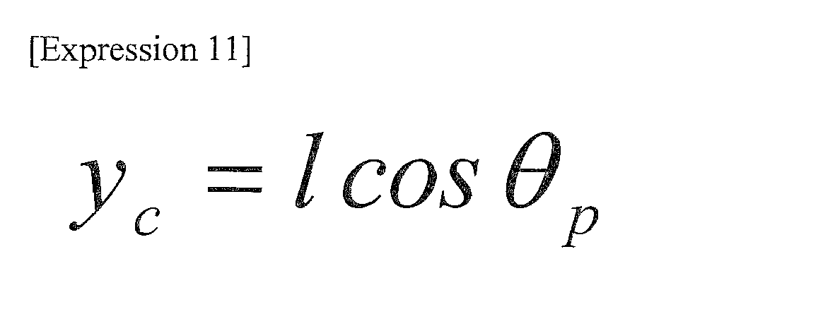
platform 401 can be expressed as Expressions (10) and (11) shown below.
- Expression (12) shown below can be obtained based on the above-shown Expressions (1), (3), (4), (6), (7) and (10).

- A relation expressed by Expression (13) shown below holds among the first wheel horizontal position x1, the second wheel horizontal position x2, and the yaw angle θy. Note that in the below-shown Expression (13), the symbol d represents the distance between the wheels (distance [m] between the first and second driving wheels 402).

- By differentiating the above-shown Expression (13) with respect to time twice, Expression (14) shown below can be obtained.

- Based on the above-shown Expressions (12) and (14), the first wheel horizontal acceleration (horizontal acceleration of the first driving wheel) d2x1/dt2 and the second wheel horizontal acceleration (horizontal acceleration of the second driving wheel) d2x2/dt2 can be expressed as Expressions (15) and (16) shown below.


- The wheel
horizontal acceleration calculator 123 calculates the first and second horizontal accelerations by using the above-shown Expressions (15) and (16), and outputs the calculated first and second horizontal accelerations to the wheelhorizontal speed calculator 125. - The
skid parameter calculator 124 respectively calculates a first skid parameter s1 indicating the skid state between thefirst driving wheel 402 and road surface and a second skid parameter s2 indicating the skid state between thesecond driving wheel 402 and road surface by using the above-shown Expressions (17) and (18), and outputs the calculated first and second skid parameters s1 and s2 to the wheel angular speedreference input calculator 121.
- Note that in the above-shown Expression (17), when the first skid parameter s1 is zero (i.e., s1=0), it means that the
first driving wheel 402 is not skidding on the road surface. Further, when the first skid parameter s1 is one (i.e., s1=1), it means that thefirst driving wheel 402 is skidding on the road surface.
- Similarly, in the above-shown Expression (18), when the second skid parameter s2 is zero (i.e., s2=0), it means that the
second driving wheel 402 is not skidding on the road surface, whereas when the second skid parameter s2 is one (i.e., s2=1), it means that thesecond driving wheel 402 is skidding on the road surface. - Next, the equation of motion of the
inverted vehicle 110 around the pitch axis, which is used for control design for thesafety controller 122, is derived. Firstly, Expression (19) shown below can be obtained by substituting the above-shown Expressions (1), (2), (4) and (5) into the above-shown Expression (9).
- Further, Expression (20) shown below can be obtained by substituting the above-shown Expressions (2) and (5) into the above-shown Expression (8).

- Further, Expression (21) shown below can be obtained by using the above-shown Expressions (3), (6), (19) and (20).
- By differentiating the above-shown Expression (11) with respect to time twice, Expression (22) shown below can be obtained.

- Expression (23) shown below, which is the equation of motion of the
inverted vehicle 110 around the pitch axis, can be obtained by substituting the above-shown Expression (22) into the above-shown Expression (12).
- The wheel angular speed
reference input calculator 121 respectively calculates a first wheel angular speed reference input for thefirst driving wheel 402 and a second wheel angular speed reference input for thesecond driving wheel 402 based on the traveling direction speed information from the traveling directionspeed input device 112, the wheel horizontal speed from the wheelhorizontal speed calculator 125, and the first and second skid parameters from theskid parameter calculator 124, and outputs the calculated first and second wheel angular speed reference inputs to thesafety controller 122. - Specifically, when the first skid parameter s1 from the
skid parameter calculator 124 is zero (i.e., s1=0), the wheel angular speedreference input calculator 121 calculates a first wheel angular speed reference input according to the traveling direction and the moving speed of theinverted vehicle 110 provided from the traveling directionspeed input device 112 and outputs the calculated first wheel angular speed reference input to thesafety controller 122. - When the first skid parameter s1 from the
skid parameter calculator 124 is one (i.e., s1=1), the wheel angular speedreference input calculator 121 calculates a first wheel angular speed reference input expressed by Expression (24) shown below and outputs the calculated first wheel angular speed reference input to thesafety controller 122. Note that in the below-shown Expression (24), the symbol δ represents a small parameter [rad/s] of the wheel angular speed reference input. - Note that when the
inverted vehicle 110 is moving forward in a forward-bent posture, it is possible to produce the maximum value of the friction reaction force exerted from the road surface in such a direction that theinverted vehicle 110 is raised by the friction reaction force by rotating the skidding first andsecond driving wheels 402 slightly faster than the traveling speed of theinverted vehicle 110. As a result, it is possible to maintain the inverted state of theinverted vehicle 110 as much as possible. Further, when theinverted vehicle 110 is moving forward in a backward-bent posture, it is possible to produce the maximum value of the friction reaction force exerted from the road surface in such a direction that theinverted vehicle 110 is raised by the friction reaction force by rotating the skidding first andsecond driving wheels 402 slightly slower than the traveling speed of theinverted vehicle 110. As a result, it is possible to maintain the inverted state of theinverted vehicle 110 as much as possible. The above-shown Expression (24) and the below-shown Expression (25) are defined based on the above-described idea.
- Similarly, when the second skid parameter s2 from the
skid parameter calculator 124 is zero (i.e., s2=0), the wheel angular speedreference input calculator 121 calculates a second wheel angular speed reference input according to the traveling direction and the moving speed of theinverted vehicle 110 provided from the traveling directionspeed input device 112 and outputs the calculated second wheel angular speed reference input to thesafety controller 122. Further, when the second skid parameter s2 from theskid parameter calculator 124 is one (i.e., s2=1), the wheel angular speedreference input calculator 121 calculates a second wheel angular speed reference input expressed by Expression (25) shown below and outputs the calculated second wheel angular speed reference input to thesafety controller 122.
- Next, a method for deriving first and second motor torques T1 and T2 for the actually skidding first and
second driving wheels 402 is explained. In the above-shown Expression (17), when the first skid parameter s1 is one (i.e., s1=1), the first motor torque T1 is derived in the following manner. Firstly, a variable q1 is introduced in Expression (26) shown below. Note that in the below-shown Expression (26), the symbol λ1 represents the degree of convergence [rad/s] of the first wheel angle deviation.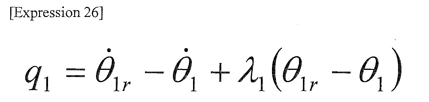
- By using the above-shown Expression (26), a candidate for a Liapunov function can be expressed by Expression (27) shown below.

- Further, by differentiating the above-shown Expression (27) with respect to time once, Expression (28) shown below can be obtained.

- In the above-shown Expression (28), a sufficient condition under which a negative fixed value is obtained for every q1 (q1≠0) can be expressed by Expression (29) shown below. Note that in the below-shown Expression (29), the symbol M1 represents the amplitude [N·m] of the first motor torque T1 when the
first driving wheel 402 is skidding.
- By using the first motor torque T1 calculated by the above-shown Expression (29), the first wheel angle θ1, which is the rotation angle of the
first driving wheel 402, can be made to converge at the first wheel angle reference input θ1r. - When the first skid parameter s1 is one (i.e., s1=1), the
safety controller 122 calculates the first motor torque T1 based on the first wheel angular speed reference input expressed by the above-shown Expression (24) provided from the wheel angular speedreference input calculator 121 by using the above-shown Expression (29). Thesafety controller 122 can bring the friction between thefirst driving wheel 402 that has just started skidding and the road surface close to the maximum static friction by outputting a motor current corresponding to the calculated first motor torque T1, and thereby prevent the skidding speed of thefirst driving wheel 402 from increasing. - Similarly, when the second skid parameter s2 is one (i.e., s2=1), the
safety controller 122 calculates the second motor torque T2 based on the second wheel angular speed reference input expressed by the above-shown Expression (25) provided from the wheel angular speedreference input calculator 121 by using Expression (30) shown below. Note that in the below-shown Expression (30), the symbol λ2 represents the degree of convergence [rad/s] of the second wheel angle deviation, and the symbol M2 represents the amplitude [N·m] of the second motor torque T2 when thesecond driving wheel 402 is skidding.
- Next, a method of deriving, when one of the first and
second driving wheels 402 is skidding, a motor torque for the other non-skidding first orsecond driving wheel 402 is explained. For example, when only thesecond driving wheel 402 is skidding, the above-shown Expression (23) can be rewritten into Expression (31) shown below by using the above-shown Expression (30).
- Here, a first motor torque T1 for controlling the pitch angle of the
platform 401 is calculated. Firstly, a variable shown in the below-shown Expression (32) and a candidate for a Liapunov function shown in the below-shown Expression (33) are introduced. In the below-shown Expression (32), the symbol λp represents the degree of convergence [rad/s] of the pitch angle deviation.

- By differentiating the above-shown Expression (33) with respect to time once, Expression (34) shown below can be obtained.

- In the above-shown Expression (34), a sufficient condition under which a negative fixed value is obtained for every qp (qp≠0) can be obtained as Expression (35) shown below by using the above-shown Expression (14). Note that in the below-shown Expression (35), the symbol Mp1 represents the amplitude [N·m] of the first motor torque T1 when the
first driving wheel 402 is not skidding.
- Further, in the above-shown Expression (35), a condition expressed by Expression (36) shown below is assumed.

- In general, when the pitch angle θp of the
platform 401 exceeds the range expressed by the above-shown Expression (36), it is very difficult for the rider to continue to be on theinverted vehicle 110 and thus the rider eventually gets off theinverted vehicle 110. As a result, the inversion control is no longer necessary. Therefore, the invertedvehicle control apparatus 100 according to this exemplary embodiment stops the inversion control (safe torque-off). - When only the
second driving wheel 402 is skidding (when the first skid parameter s1 is zero (s1=0) and the second skid parameter s2 is one (s2=1)), thesafety controller 122 controls thefirst motor 113 based on the first motor torque T1 expressed by the above-shown Expression (35). As a result, it is possible to maintain the inverted state of theinverted vehicle 110 while making the pitch angle θp of theplatform 401 converge at zero. - On the other hand, when only the
first driving wheel 402 is skidding (when the first skid parameter s1 is one (s1=1) and the second skid parameter s2 is zero (s2=0)), thesafety controller 122 controls thesecond motor 113 based on the second motor torque T2 expressed by Expression (37) shown below. As a result, it is possible to maintain the inverted state of theinverted vehicle 110. Note that in the below-shown Expression (37), the symbol Mp2 represents the amplitude [N·m] of the second motor torque T2 when thesecond driving wheel 402 is not skidding.
- Note that although the above-described equation of motion does not include any term for disturbance, it is possible to suppress disturbance by setting the amplitudes of the first and second motor torques T1 and T2 to sufficiently large values to allow the maximum value of the absolute value of the disturbance.
- Next, a simulation result of the inverted
vehicle control apparatus 100 according to this exemplary embodiment is explained in detail. Firstly, each parameter is set as shown below in this simulation. Note that the symbol ng represents a reduction ratio and the symbol T represents a control cycle.
- This simulation is carried out on the assumption that, for example, only the
second driving wheel 402 moves on a road surface having low friction such as a frozen puddle when theinverted vehicle 110 is traveling.Fig. 2 is a graph showing a simulation result of the invertedvehicle control apparatus 100 according to this exemplary embodiment, and shows temporal changes of the pitch angle of the platform. InFig. 2 , the solid line (1) represents pitch angles θp obtained by the invertedvehicle control apparatus 100 according to this exemplary embodiment, and the broken line (2) represents pitch angles obtained by an inverted vehicle control apparatus in related art. In this example, the related-art inverted vehicle control apparatus performs a sliding mode control that is designed under the assumption that both the first and second driving wheels are not skidding. - In
Fig. 2 , at a time 0[s], thesecond driving wheel 402 moves on a low-friction road surface and thefirst driving wheel 402 moves on a road surface having a kinetic-friction coefficient of 0.9. Further, it is assumed that the actual value of the moment of inertia Jp of thechassis 404 around the pitch angle is larger than the assumed value used in the control design in the above-shown Expression (35) by about 20[%]. Further, it is assumed that there is an inverted saw-tooth disturbance having a peak value of 4×10³[N·m] and a cycle of 10T[s] for thefirst driving wheel 402 due to the unevenness of the road surface. - As can be seen from
Fig. 2 , in the related-art inverted vehicle control apparatus, the rider inclines backward at a pitch angle of 0.1[rad] or larger when the rider tries to maintain the inverted state of the inverted vehicle. Further, in this simulation, since the rider and the chassis are modeled as one integrated rigid body, the inverted state can be maintained at a time 0.2[s]. However, there is a possibility that a real rider will react to the backward inclination of the inverted vehicle and, after that, fall down backward when the rider inclines the inverted vehicle forward. - In contrast to this, it can be seen that in the inverted
vehicle control apparatus 100 according to this exemplary embodiment, the inverted vehicle hardly inclines backward and thus the inverted state of theinverted vehicle 110 can be safely maintained. -
Fig. 3 is a graph showing a simulation result of the inverted vehicle control apparatus according to this exemplary embodiment, and shows temporal changes of the first motor torque. InFig. 2 , the solid line (3) represents first motor torques obtained by the invertedvehicle control apparatus 100 according to this exemplary embodiment, and the broken line (4) represents first motor torques obtained by the related-art inverted vehicle control apparatus. - In the related-art inverted vehicle control apparatus, the sign of its first motor torque changes at an interval of 0.7[s] or larger. In contrast to this, in the inverted
vehicle control apparatus 100 according to this exemplary embodiment, the sign of its first motor torque T1 changes at small intervals at and after a time 0.1[s]. This means that the phase trajectory of the invertedvehicle control apparatus 100 according to this exemplary embodiment converges on the switching plane faster than the phase trajectory of the related-art inverted vehicle control apparatus. That is, this means that the invertedvehicle control apparatus 100 according to this exemplary embodiment has a higher ability for stabilizing the posture of theinverted vehicle 110 than that of the related-art inverted vehicle control apparatus. - As can be seen from the above-shown simulation results, when one of the first and
second driving wheels 402 of theinverted vehicle 110 is skidding on the road surface, the inverted state can be maintained by using thenon-skidding driving wheel 402 alone without widely inclining theinverted vehicle 110 backward. Therefore, it is possible to safely control theinverted vehicle 110 without feeling any anxiety. - As explained above, the inverted
vehicle control apparatus 100 according to this exemplary embodiment controls, based on operation information entered by the rider, the first orsecond driving wheel 402 for which no skid is detected, and controls the first orsecond driving wheel 402 for which a skid is detected so that the friction reaction force exerted from the road surface to the first orsecond driving wheel 402 is exerted in such a direction that theinverted vehicle 110 is raised by the friction reaction force. In this manner, by appropriately controlling not only thenon-skidding driving wheel 402 but also theskidding driving wheel 402, the inverted state of theinverted vehicle 110 can be maintained as much as possible. Further, even if the inverted state cannot be maintained, the falling-down impact can be minimized, thus allowing the rider to get off the inverted vehicle safely. That is, it is possible to make theinverted vehicle 110 travel safely or stop safely even on a low-friction road surface. - Note that the present invention is not limited to the above-described exemplary embodiments, and those exemplary embodiments can be modified as appropriate without departing from the spirit and scope of the present invention. For example, although the present invention is applied to the
inverted vehicle 110 including a pair of first andsecond driving wheels 402 in the above-described exemplary embodiment, the present invention is not limited to such inverted vehicles. That is, the present invention can be applied to an inverted vehicle including three or more driving wheels or an inverted vehicle including a coupled driving wheel(s). - Further, although an example in which a disturbance such as changes in the rider's weight and effects of unevenness of the road surface is taken into consideration is explained in the above-described exemplary embodiment, the present invention is not limited to such examples. For example, the present invention can be applied to a case where there is an arbitrary disturbance such as when a head wind is blowing and when the inverted vehicle comes into contact with a nearby person, an object, or the like.
- Further, although the present invention is explained on the assumption it is implemented by a hardware configuration in the above-described exemplary embodiment, the present invention is not limited to such hardware configurations. In the present invention, the above-described processes performed by the
control device 120 can be implemented by causing a CPU to execute a computer program. - The above-described program can be stored in various types of non-transitory computer readable media and thereby supplied to computers. The non-transitory computer readable media includes various types of tangible storage media. Examples of the non-transitory computer readable media include a magnetic recording medium (such as a flexible disk, a magnetic tape, and a hard disk drive), a magneto-optic recording medium (such as a magneto-optic disk), a CD-ROM (Read Only Memory), a CD-R, and a CD-R/W, and a semiconductor memory (such as a mask ROM, a PROM (Programmable ROM), an EPROM (Erasable PROM), a flash ROM, and a RAM (Random Access Memory)).
- Further, the program can be supplied to computers by using various types of transitory computer readable media. Examples of the transitory computer readable media include an electrical signal, an optical signal, and an electromagnetic wave. The transitory computer readable media can be used to supply programs to a computer through a wire communication path such as an electrical wire and an optical fiber, or wireless communication path.
- The present invention can be applied to an inverted vehicle control apparatus that can make an inverted vehicle travel safely even on a low-friction road surface by controlling a plurality of driving wheels.
-
- 100
- INVERTED VEHICLE CONTROL APPARATUS
- 110
- INVERTED VEHICLE
- 111
- CONTROL MECHANISM
- 112
- TRAVELING DIRECTION SPEED INPUT DEVICE
- 113
- FIRST MOTOR, SECOND MOTOR
- 114
- WHEEL ANGULAR SPEED DETECTOR
- 115
- PITCH ANGLE DETECTOR
- 116
- YAW ANGLE DETECTOR
- 120
- CONTROL DEVICE
- 121
- WHEEL ANGULAR SPEED REFERENCE INPUT CALCULATOR
- 122
- SAFETY CONTROLLER
- 123
- WHEEL HORIZONTAL ACCELERATION CALCULATOR
- 124
- SKID PARAMETER CALCULATOR
- 125
- WHEEL HORIZONTAL SPEED CALCULATOR
- 401
- PLATFORM
- 402
- FIRST DRIVING WHEEL, SECOND DRIVING WHEEL
- 403
- HANDLEBAR
- 404
- CHASSIS
Claims (11)
- An inverted vehicle control apparatus comprising:a plurality of driving wheels provided in an inverted vehicle;a plurality of drive means each of which drives a respective one of the plurality of driving wheels;skid detection means for detecting a skid state between the plurality of driving wheels and a road surface;operation information acquisition means for acquiring operation information of a rider; andcontrol means for controlling driving of the drive means and thereby controlling the plurality of driving wheels, whereinthe control means controls, based on the operation information acquired by the operation information acquisition means, the driving wheel for which no skid is detected by the skid detection means, andthe control means controls the driving wheel for which a skid is detected by the skid detection means so that a friction reaction force exerted from the road surface to the driving wheel is exerted in such a direction that the inverted vehicle is raised by the friction reaction force.
- The inverted vehicle control apparatus according to Claim 1, further comprising:pitch angle detection means for detecting a pitch angle of the inverted vehicle; andwheel horizontal speed calculation means for calculating a horizontal speed of the driving wheel of the inverted vehicle,wherein the control means controls the driving wheel for which the skid is detected by the skid detection means, based on the pitch angle of the inverted vehicle detected by the pitch angle detection means and the horizontal speed of the driving wheel calculated by the wheel horizontal speed calculation means.
- The inverted vehicle control apparatus according to Claim 1 or 2, wherein the control means comprises:wheel angular speed reference input calculation means for calculating an angular speed reference input of the driving wheel based on operation information acquired by the operation information acquisition means, a horizontal moving speed of the driving wheel calculated by the wheel horizontal speed calculation means, and skid information of the driving wheel detected by the skid detection means; andsafety control means for maintaining an inverted state of the inverted vehicle by controlling the driving of the drive means based on the angular speed reference input of the driving wheel calculated by the wheel angular speed reference input calculation means.
- The inverted vehicle control apparatus according to Claim 3, wherein the wheel angular speed reference input calculation means calculates the angular speed reference input for the driving wheel for which the skid is detected by the skid detection means, by using an expression shown below,
 where: rw is a radius of the driving wheel; a derivative value of x is a horizontal speed of the driving wheel calculated by the wheel horizontal speed calculation means; θp is a pitch angle of the inverted vehicle detected by the pitch angle detection means; a derivative value of θr is an angular speed reference input of the driving wheel; and δ is a small parameter of the angular speed reference input.
 - The inverted vehicle control apparatus according to any one of Claims 1 to 4, wherein the operation information acquisition means comprises traveling direction speed input means for outputting a traveling direction and a traveling speed of the inverted vehicle based on the operation information entered by the rider.
- The inverted vehicle control apparatus according to any one of Claims 1 to 5, further comprising:wheel angular speed detection means for detecting an angular speed of the driving wheel;yaw angle detection means for detecting a yaw angle of the inverted vehicle; andwheel horizontal acceleration calculation means for calculating a horizontal acceleration of the driving wheel based on the angular speed of the driving wheel detected by the wheel angular speed detection means, the pitch angle of the inverted vehicle detected by the pitch angle detection means, the yaw angle of the inverted vehicle detected by the yaw angle detection means, and a control signal for controlling the drive means.
- The inverted vehicle control apparatus according to Claim 6, wherein the skid detection means comprises skid parameter calculation means for calculating a skid parameter indicating whether the driving wheel is skidding or not, based on the angular speed of the driving wheel detected by the wheel angular speed detection means and the horizontal acceleration of the driving wheel calculated by the wheel horizontal acceleration calculation means, and outputting the calculated skid parameter to the control means.
- The inverted vehicle control apparatus according to Claim 6 or 7, wherein the wheel horizontal acceleration calculation means calculates a horizontal acceleration of the first and second driving wheels by using an expression shown below,

 where: mw is a mass of the first and second driving wheels; Jw is a moment of inertia of the first and second driving wheels; x1 is a horizontal position of the first driving wheel; x2 is a horizontal position of the second driving wheel; θ1 is an angle of the first driving wheel; θ2 is an angle of the second driving wheel; rw is a radius of the first and second driving wheels; T1 is a driving torque of the first drive means; T2 is a driving torque of the second drive means; mc is a mass of a chassis of the inverted vehicle; θp is a pitch angle of the inverted vehicle; θy is a yaw angle of the inverted vehicle; and 1 is a distance between an axle of the inverted vehicle and a center of gravity of the chassis.
 - The inverted vehicle control apparatus according to Claim 2 or 3, wherein the safety control means calculates a driving torque T for the skidding driving wheel by using an expression shown below,
 where: λ is a degree of convergence of an angle deviation of the driving wheel; M is a driving torque of the driving means when the driving wheel is skidding; Jw is a moment of inertia of the driving wheel; rw is a radius of the driving wheel; θr is an angular speed reference input from the wheel angular speed reference input calculation means; θ is a wheel angle; and Hg is a horizontal reaction force exerted from the road surface to the driving wheel.
 - A control method for an inverted vehicle control apparatus, comprising:a step of detecting a skid state between a plurality of driving wheels provided in an inverted vehicle and a road surface;a step of acquiring operation information of a rider; anda step of controlling, based on the acquired operation information, the driving wheel for which no skid is detected, and controlling the driving wheel for which a skid is detected so that a friction reaction force exerted from the road surface to the driving wheel is exerted in such a direction that the inverted vehicle is raised by the friction reaction force.
- A program for an inverted vehicle control apparatus, for causing a computer to execute:a process of detecting a skid state between a plurality of driving wheels provided in an inverted vehicle and a road surface; anda process of controlling, based on operation information of a rider, the driving wheel for which no skid is detected, and controlling the driving wheel for which a skid is detected so that a friction reaction force exerted from the road surface to the driving wheel is exerted in such a direction that the inverted vehicle is raised by the friction reaction force.
Applications Claiming Priority (1)
| Application Number | Priority Date | Filing Date | Title |
|---|---|---|---|
| PCT/JP2011/004141 WO2013014696A1 (en) | 2011-07-22 | 2011-07-22 | Inverted mobile body control device, and method and program therefor |
Publications (3)
| Publication Number | Publication Date |
|---|---|
| EP2735500A1 true EP2735500A1 (en) | 2014-05-28 |
| EP2735500A4 EP2735500A4 (en) | 2015-04-29 |
| EP2735500B1 EP2735500B1 (en) | 2016-08-17 |
Family
ID=47600593
Family Applications (1)
| Application Number | Title | Priority Date | Filing Date |
|---|---|---|---|
| EP11869837.2A Not-in-force EP2735500B1 (en) | 2011-07-22 | 2011-07-22 | Inverted mobile body control device, and method and program therefor |
Country Status (5)
| Country | Link |
|---|---|
| US (1) | US9399405B2 (en) |
| EP (1) | EP2735500B1 (en) |
| JP (1) | JP5761347B2 (en) |
| CN (1) | CN103687783B (en) |
| WO (1) | WO2013014696A1 (en) |
Families Citing this family (12)
| Publication number | Priority date | Publication date | Assignee | Title |
|---|---|---|---|---|
| CN106166961B (en) * | 2016-05-24 | 2018-01-16 | 吴健章 | A kind of micro- racing car intelligence control system |
| CN211273514U (en) | 2016-06-02 | 2020-08-18 | 未来动力公司 | Electric vehicle |
| US11040756B2 (en) | 2016-06-13 | 2021-06-22 | Ninebot (Beijing) Tech Co., Ltd | Power control method and apparatus, vehicle and computer storage medium |
| CN106080879B (en) * | 2016-06-13 | 2018-12-21 | 纳恩博(北京)科技有限公司 | The motion control method and system of scooter and scooter |
| US9999827B2 (en) * | 2016-10-25 | 2018-06-19 | Future Motion, Inc. | Self-balancing skateboard with strain-based controls and suspensions |
| US12005340B2 (en) | 2020-10-06 | 2024-06-11 | Future Motion, Inc. | Suspension systems for an electric skateboard |
| US11123629B1 (en) | 2020-10-06 | 2021-09-21 | Future Motion, Inc. | Suspension systems for an electric skateboard |
| US11840303B2 (en) | 2021-06-11 | 2023-12-12 | Future Motion, Inc. | Suspension system for a one-wheeled vehicle |
| US11273364B1 (en) | 2021-06-30 | 2022-03-15 | Future Motion, Inc. | Self-stabilizing skateboard |
| US11299059B1 (en) | 2021-10-20 | 2022-04-12 | Future Motion, Inc. | Self-stabilizing skateboard |
| US11890528B1 (en) | 2022-11-17 | 2024-02-06 | Future Motion, Inc. | Concave side rails for one-wheeled vehicles |
| US12187373B1 (en) | 2024-02-29 | 2025-01-07 | Future Motion, Inc. | Skateboard footpads having foot engagement structures and traction inserts |
Family Cites Families (13)
| Publication number | Priority date | Publication date | Assignee | Title |
|---|---|---|---|---|
| US7275607B2 (en) * | 1999-06-04 | 2007-10-02 | Deka Products Limited Partnership | Control of a personal transporter based on user position |
| US6408240B1 (en) * | 2000-10-13 | 2002-06-18 | Deka Products Limited Partnership | Traction control for a personal transporter |
| US6866107B2 (en) * | 2000-10-13 | 2005-03-15 | Deka Products Limited Partnership | Method and device for battery load sharing |
| IL155390A0 (en) | 2000-10-13 | 2003-11-23 | Deka Products Lp | Control of a personal transporter |
| JP2004345608A (en) * | 2003-05-26 | 2004-12-09 | Sony Corp | Vehicles that can be steered by moving the center of gravity |
| US7363993B2 (en) * | 2003-11-04 | 2008-04-29 | Toyota Jidosha Kabushiki Kaisha | Traveling apparatus and method for controlling thereof |
| JP4635692B2 (en) * | 2005-04-12 | 2011-02-23 | トヨタ自動車株式会社 | Vehicle apparatus and control method thereof |
| JP5519093B2 (en) * | 2006-08-03 | 2014-06-11 | トヨタ自動車株式会社 | Traveling apparatus and braking control method for traveling apparatus |
| JP5024652B2 (en) | 2006-09-15 | 2012-09-12 | 株式会社エクォス・リサーチ | vehicle |
| JP4779982B2 (en) * | 2007-02-02 | 2011-09-28 | トヨタ自動車株式会社 | MOBILE BODY AND METHOD FOR CONTROLLING MOBILE BODY |
| WO2008120507A1 (en) | 2007-03-29 | 2008-10-09 | Equos Research Co., Ltd. | Vehicle |
| JP4600539B2 (en) * | 2008-07-29 | 2010-12-15 | トヨタ自動車株式会社 | TRAVEL DEVICE AND TRAVEL DEVICE CONTROL METHOD |
| JP5398446B2 (en) * | 2009-09-18 | 2014-01-29 | 本田技研工業株式会社 | Drive device |
-
2011
- 2011-07-22 US US14/233,914 patent/US9399405B2/en not_active Expired - Fee Related
- 2011-07-22 JP JP2013525429A patent/JP5761347B2/en not_active Expired - Fee Related
- 2011-07-22 EP EP11869837.2A patent/EP2735500B1/en not_active Not-in-force
- 2011-07-22 CN CN201180072387.6A patent/CN103687783B/en not_active Expired - Fee Related
- 2011-07-22 WO PCT/JP2011/004141 patent/WO2013014696A1/en not_active Ceased
Also Published As
| Publication number | Publication date |
|---|---|
| CN103687783A (en) | 2014-03-26 |
| WO2013014696A1 (en) | 2013-01-31 |
| CN103687783B (en) | 2016-04-27 |
| JP5761347B2 (en) | 2015-08-12 |
| EP2735500B1 (en) | 2016-08-17 |
| JPWO2013014696A1 (en) | 2015-02-23 |
| US9399405B2 (en) | 2016-07-26 |
| US20140172262A1 (en) | 2014-06-19 |
| EP2735500A4 (en) | 2015-04-29 |
Similar Documents
| Publication | Publication Date | Title |
|---|---|---|
| EP2735500B1 (en) | Inverted mobile body control device, and method and program therefor | |
| KR101156822B1 (en) | Mobile and control method of mobile | |
| CN100557539C (en) | Inverted two-wheel walking robot and control method thereof | |
| JP4600539B2 (en) | TRAVEL DEVICE AND TRAVEL DEVICE CONTROL METHOD | |
| EP2083340B1 (en) | Inverted type movable body and control method thereof | |
| US8935050B2 (en) | Moving body control system, moving body control method, and non-transitory computer readable medium storing control program | |
| US20230104727A1 (en) | Travel control device, vehicle, travel control method, and program | |
| EP2426566B1 (en) | Control portion for inverted vehicle | |
| US8731758B2 (en) | Vehicle control apparatus, control method thereof, and control software | |
| Yetkin et al. | Stabilizing control of an autonomous bicycle | |
| US8678124B2 (en) | Inverted pendulum type vehicle | |
| JP5617595B2 (en) | Inverted moving body and control method thereof | |
| JP5488095B2 (en) | Inverted moving body and control method thereof | |
| JP5772373B2 (en) | Inverted moving body control device and control method thereof | |
| JP5316336B2 (en) | Inverted type moving body, its control method and control program | |
| JP5786633B2 (en) | MOBILE BODY CONTROL DEVICE, ITS CONTROL METHOD, AND PROGRAM | |
| JP4992754B2 (en) | Inverted wheeled mobile robot and its control method | |
| JP5652043B2 (en) | Inverted type moving body, its control method and control program | |
| JP6183328B2 (en) | Inverted balance training apparatus and inverted balance training method | |
| JP2017043222A (en) | Mobile device and method for controlling mobile device | |
| JP5861651B2 (en) | MOBILE DEVICE, MOBILE DEVICE CONTROL METHOD, AND PROGRAM | |
| JP6217582B2 (en) | Inverted moving body and control method thereof | |
| CN121697613A (en) | The operation control method of scooters and scooters, products and storage media | |
| JP5966882B2 (en) | MOBILE BODY CONTROL DEVICE, MOBILE BODY CONTROL METHOD, AND PROGRAM | |
| JP2019151300A (en) | Method for estimating degree of handle operation of inverted coaxial two-wheel vehicle |
Legal Events
| Date | Code | Title | Description |
|---|---|---|---|
| PUAI | Public reference made under article 153(3) epc to a published international application that has entered the european phase |
Free format text: ORIGINAL CODE: 0009012 |
|
| 17P | Request for examination filed |
Effective date: 20140221 |
|
| AK | Designated contracting states |
Kind code of ref document: A1 Designated state(s): AL AT BE BG CH CY CZ DE DK EE ES FI FR GB GR HR HU IE IS IT LI LT LU LV MC MK MT NL NO PL PT RO RS SE SI SK SM TR |
|
| DAX | Request for extension of the european patent (deleted) | ||
| RA4 | Supplementary search report drawn up and despatched (corrected) |
Effective date: 20150327 |
|
| RIC1 | Information provided on ipc code assigned before grant |
Ipc: B62K 17/00 20060101AFI20150323BHEP Ipc: B62K 3/00 20060101ALI20150323BHEP |
|
| GRAP | Despatch of communication of intention to grant a patent |
Free format text: ORIGINAL CODE: EPIDOSNIGR1 |
|
| INTG | Intention to grant announced |
Effective date: 20160210 |
|
| GRAS | Grant fee paid |
Free format text: ORIGINAL CODE: EPIDOSNIGR3 |
|
| GRAA | (expected) grant |
Free format text: ORIGINAL CODE: 0009210 |
|
| AK | Designated contracting states |
Kind code of ref document: B1 Designated state(s): AL AT BE BG CH CY CZ DE DK EE ES FI FR GB GR HR HU IE IS IT LI LT LU LV MC MK MT NL NO PL PT RO RS SE SI SK SM TR |
|
| REG | Reference to a national code |
Ref country code: GB Ref legal event code: FG4D |
|
| REG | Reference to a national code |
Ref country code: CH Ref legal event code: EP |
|
| REG | Reference to a national code |
Ref country code: IE Ref legal event code: FG4D |
|
| REG | Reference to a national code |
Ref country code: AT Ref legal event code: REF Ref document number: 820766 Country of ref document: AT Kind code of ref document: T Effective date: 20160915 |
|
| REG | Reference to a national code |
Ref country code: DE Ref legal event code: R096 Ref document number: 602011029497 Country of ref document: DE |
|
| REG | Reference to a national code |
Ref country code: NL Ref legal event code: MP Effective date: 20160817 |
|
| REG | Reference to a national code |
Ref country code: LT Ref legal event code: MG4D |
|
| REG | Reference to a national code |
Ref country code: AT Ref legal event code: MK05 Ref document number: 820766 Country of ref document: AT Kind code of ref document: T Effective date: 20160817 |
|
| PG25 | Lapsed in a contracting state [announced via postgrant information from national office to epo] |
Ref country code: LT Free format text: LAPSE BECAUSE OF FAILURE TO SUBMIT A TRANSLATION OF THE DESCRIPTION OR TO PAY THE FEE WITHIN THE PRESCRIBED TIME-LIMIT Effective date: 20160817 Ref country code: RS Free format text: LAPSE BECAUSE OF FAILURE TO SUBMIT A TRANSLATION OF THE DESCRIPTION OR TO PAY THE FEE WITHIN THE PRESCRIBED TIME-LIMIT Effective date: 20160817 Ref country code: IT Free format text: LAPSE BECAUSE OF FAILURE TO SUBMIT A TRANSLATION OF THE DESCRIPTION OR TO PAY THE FEE WITHIN THE PRESCRIBED TIME-LIMIT Effective date: 20160817 Ref country code: NL Free format text: LAPSE BECAUSE OF FAILURE TO SUBMIT A TRANSLATION OF THE DESCRIPTION OR TO PAY THE FEE WITHIN THE PRESCRIBED TIME-LIMIT Effective date: 20160817 Ref country code: FI Free format text: LAPSE BECAUSE OF FAILURE TO SUBMIT A TRANSLATION OF THE DESCRIPTION OR TO PAY THE FEE WITHIN THE PRESCRIBED TIME-LIMIT Effective date: 20160817 Ref country code: HR Free format text: LAPSE BECAUSE OF FAILURE TO SUBMIT A TRANSLATION OF THE DESCRIPTION OR TO PAY THE FEE WITHIN THE PRESCRIBED TIME-LIMIT Effective date: 20160817 Ref country code: NO Free format text: LAPSE BECAUSE OF FAILURE TO SUBMIT A TRANSLATION OF THE DESCRIPTION OR TO PAY THE FEE WITHIN THE PRESCRIBED TIME-LIMIT Effective date: 20161117 |
|
| PG25 | Lapsed in a contracting state [announced via postgrant information from national office to epo] |
Ref country code: PT Free format text: LAPSE BECAUSE OF FAILURE TO SUBMIT A TRANSLATION OF THE DESCRIPTION OR TO PAY THE FEE WITHIN THE PRESCRIBED TIME-LIMIT Effective date: 20161219 Ref country code: GR Free format text: LAPSE BECAUSE OF FAILURE TO SUBMIT A TRANSLATION OF THE DESCRIPTION OR TO PAY THE FEE WITHIN THE PRESCRIBED TIME-LIMIT Effective date: 20161118 Ref country code: LV Free format text: LAPSE BECAUSE OF FAILURE TO SUBMIT A TRANSLATION OF THE DESCRIPTION OR TO PAY THE FEE WITHIN THE PRESCRIBED TIME-LIMIT Effective date: 20160817 Ref country code: AT Free format text: LAPSE BECAUSE OF FAILURE TO SUBMIT A TRANSLATION OF THE DESCRIPTION OR TO PAY THE FEE WITHIN THE PRESCRIBED TIME-LIMIT Effective date: 20160817 Ref country code: SE Free format text: LAPSE BECAUSE OF FAILURE TO SUBMIT A TRANSLATION OF THE DESCRIPTION OR TO PAY THE FEE WITHIN THE PRESCRIBED TIME-LIMIT Effective date: 20160817 Ref country code: ES Free format text: LAPSE BECAUSE OF FAILURE TO SUBMIT A TRANSLATION OF THE DESCRIPTION OR TO PAY THE FEE WITHIN THE PRESCRIBED TIME-LIMIT Effective date: 20160817 Ref country code: PL Free format text: LAPSE BECAUSE OF FAILURE TO SUBMIT A TRANSLATION OF THE DESCRIPTION OR TO PAY THE FEE WITHIN THE PRESCRIBED TIME-LIMIT Effective date: 20160817 |
|
| REG | Reference to a national code |
Ref country code: DE Ref legal event code: R084 Ref document number: 602011029497 Country of ref document: DE |
|
| PG25 | Lapsed in a contracting state [announced via postgrant information from national office to epo] |
Ref country code: RO Free format text: LAPSE BECAUSE OF FAILURE TO SUBMIT A TRANSLATION OF THE DESCRIPTION OR TO PAY THE FEE WITHIN THE PRESCRIBED TIME-LIMIT Effective date: 20160817 Ref country code: EE Free format text: LAPSE BECAUSE OF FAILURE TO SUBMIT A TRANSLATION OF THE DESCRIPTION OR TO PAY THE FEE WITHIN THE PRESCRIBED TIME-LIMIT Effective date: 20160817 |
|
| REG | Reference to a national code |
Ref country code: GB Ref legal event code: 746 Effective date: 20170421 |
|
| REG | Reference to a national code |
Ref country code: DE Ref legal event code: R097 Ref document number: 602011029497 Country of ref document: DE |
|
| PG25 | Lapsed in a contracting state [announced via postgrant information from national office to epo] |
Ref country code: BG Free format text: LAPSE BECAUSE OF FAILURE TO SUBMIT A TRANSLATION OF THE DESCRIPTION OR TO PAY THE FEE WITHIN THE PRESCRIBED TIME-LIMIT Effective date: 20161117 Ref country code: BE Free format text: LAPSE BECAUSE OF FAILURE TO SUBMIT A TRANSLATION OF THE DESCRIPTION OR TO PAY THE FEE WITHIN THE PRESCRIBED TIME-LIMIT Effective date: 20160817 Ref country code: SK Free format text: LAPSE BECAUSE OF FAILURE TO SUBMIT A TRANSLATION OF THE DESCRIPTION OR TO PAY THE FEE WITHIN THE PRESCRIBED TIME-LIMIT Effective date: 20160817 Ref country code: CZ Free format text: LAPSE BECAUSE OF FAILURE TO SUBMIT A TRANSLATION OF THE DESCRIPTION OR TO PAY THE FEE WITHIN THE PRESCRIBED TIME-LIMIT Effective date: 20160817 Ref country code: SM Free format text: LAPSE BECAUSE OF FAILURE TO SUBMIT A TRANSLATION OF THE DESCRIPTION OR TO PAY THE FEE WITHIN THE PRESCRIBED TIME-LIMIT Effective date: 20160817 Ref country code: DK Free format text: LAPSE BECAUSE OF FAILURE TO SUBMIT A TRANSLATION OF THE DESCRIPTION OR TO PAY THE FEE WITHIN THE PRESCRIBED TIME-LIMIT Effective date: 20160817 |
|
| REG | Reference to a national code |
Ref country code: FR Ref legal event code: PLFP Year of fee payment: 7 |
|
| PLBE | No opposition filed within time limit |
Free format text: ORIGINAL CODE: 0009261 |
|
| STAA | Information on the status of an ep patent application or granted ep patent |
Free format text: STATUS: NO OPPOSITION FILED WITHIN TIME LIMIT |
|
| 26N | No opposition filed |
Effective date: 20170518 |
|
| PG25 | Lapsed in a contracting state [announced via postgrant information from national office to epo] |
Ref country code: SI Free format text: LAPSE BECAUSE OF FAILURE TO SUBMIT A TRANSLATION OF THE DESCRIPTION OR TO PAY THE FEE WITHIN THE PRESCRIBED TIME-LIMIT Effective date: 20160817 |
|
| REG | Reference to a national code |
Ref country code: CH Ref legal event code: PL |
|
| REG | Reference to a national code |
Ref country code: IE Ref legal event code: MM4A |
|
| PG25 | Lapsed in a contracting state [announced via postgrant information from national office to epo] |
Ref country code: CH Free format text: LAPSE BECAUSE OF NON-PAYMENT OF DUE FEES Effective date: 20170731 Ref country code: IE Free format text: LAPSE BECAUSE OF NON-PAYMENT OF DUE FEES Effective date: 20170722 Ref country code: LI Free format text: LAPSE BECAUSE OF NON-PAYMENT OF DUE FEES Effective date: 20170731 |
|
| REG | Reference to a national code |
Ref country code: FR Ref legal event code: PLFP Year of fee payment: 8 |
|
| PG25 | Lapsed in a contracting state [announced via postgrant information from national office to epo] |
Ref country code: LU Free format text: LAPSE BECAUSE OF NON-PAYMENT OF DUE FEES Effective date: 20170722 |
|
| PG25 | Lapsed in a contracting state [announced via postgrant information from national office to epo] |
Ref country code: MT Free format text: LAPSE BECAUSE OF NON-PAYMENT OF DUE FEES Effective date: 20170722 |
|
| PG25 | Lapsed in a contracting state [announced via postgrant information from national office to epo] |
Ref country code: AL Free format text: LAPSE BECAUSE OF FAILURE TO SUBMIT A TRANSLATION OF THE DESCRIPTION OR TO PAY THE FEE WITHIN THE PRESCRIBED TIME-LIMIT Effective date: 20160817 |
|
| PG25 | Lapsed in a contracting state [announced via postgrant information from national office to epo] |
Ref country code: HU Free format text: LAPSE BECAUSE OF FAILURE TO SUBMIT A TRANSLATION OF THE DESCRIPTION OR TO PAY THE FEE WITHIN THE PRESCRIBED TIME-LIMIT; INVALID AB INITIO Effective date: 20110722 Ref country code: MC Free format text: LAPSE BECAUSE OF FAILURE TO SUBMIT A TRANSLATION OF THE DESCRIPTION OR TO PAY THE FEE WITHIN THE PRESCRIBED TIME-LIMIT Effective date: 20160817 |
|
| PG25 | Lapsed in a contracting state [announced via postgrant information from national office to epo] |
Ref country code: CY Free format text: LAPSE BECAUSE OF NON-PAYMENT OF DUE FEES Effective date: 20160817 |
|
| PG25 | Lapsed in a contracting state [announced via postgrant information from national office to epo] |
Ref country code: MK Free format text: LAPSE BECAUSE OF FAILURE TO SUBMIT A TRANSLATION OF THE DESCRIPTION OR TO PAY THE FEE WITHIN THE PRESCRIBED TIME-LIMIT Effective date: 20160817 |
|
| PG25 | Lapsed in a contracting state [announced via postgrant information from national office to epo] |
Ref country code: TR Free format text: LAPSE BECAUSE OF FAILURE TO SUBMIT A TRANSLATION OF THE DESCRIPTION OR TO PAY THE FEE WITHIN THE PRESCRIBED TIME-LIMIT Effective date: 20160817 |
|
| PG25 | Lapsed in a contracting state [announced via postgrant information from national office to epo] |
Ref country code: IS Free format text: LAPSE BECAUSE OF FAILURE TO SUBMIT A TRANSLATION OF THE DESCRIPTION OR TO PAY THE FEE WITHIN THE PRESCRIBED TIME-LIMIT Effective date: 20161217 |
|
| PGFP | Annual fee paid to national office [announced via postgrant information from national office to epo] |
Ref country code: GB Payment date: 20220606 Year of fee payment: 12 |
|
| PGFP | Annual fee paid to national office [announced via postgrant information from national office to epo] |
Ref country code: FR Payment date: 20220609 Year of fee payment: 12 |
|
| PGFP | Annual fee paid to national office [announced via postgrant information from national office to epo] |
Ref country code: DE Payment date: 20220531 Year of fee payment: 12 |
|
| P01 | Opt-out of the competence of the unified patent court (upc) registered |
Effective date: 20230427 |
|
| REG | Reference to a national code |
Ref country code: DE Ref legal event code: R119 Ref document number: 602011029497 Country of ref document: DE |
|
| GBPC | Gb: european patent ceased through non-payment of renewal fee |
Effective date: 20230722 |
|
| PG25 | Lapsed in a contracting state [announced via postgrant information from national office to epo] |
Ref country code: DE Free format text: LAPSE BECAUSE OF NON-PAYMENT OF DUE FEES Effective date: 20240201 Ref country code: GB Free format text: LAPSE BECAUSE OF NON-PAYMENT OF DUE FEES Effective date: 20230722 |
|
| PG25 | Lapsed in a contracting state [announced via postgrant information from national office to epo] |
Ref country code: FR Free format text: LAPSE BECAUSE OF NON-PAYMENT OF DUE FEES Effective date: 20230731 |