EP2735494A2 - Steering system - Google Patents
Steering system Download PDFInfo
- Publication number
- EP2735494A2 EP2735494A2 EP13193048.9A EP13193048A EP2735494A2 EP 2735494 A2 EP2735494 A2 EP 2735494A2 EP 13193048 A EP13193048 A EP 13193048A EP 2735494 A2 EP2735494 A2 EP 2735494A2
- Authority
- EP
- European Patent Office
- Prior art keywords
- sliding resistance
- outer tube
- end portion
- inner tube
- resistance reducing
- Prior art date
- Legal status (The legal status is an assumption and is not a legal conclusion. Google has not performed a legal analysis and makes no representation as to the accuracy of the status listed.)
- Withdrawn
Links
- 230000000717 retained effect Effects 0.000 claims abstract description 45
- 230000035939 shock Effects 0.000 claims abstract description 11
- 238000005096 rolling process Methods 0.000 claims description 36
- 230000004048 modification Effects 0.000 description 12
- 238000012986 modification Methods 0.000 description 12
- 239000000470 constituent Substances 0.000 description 7
- 239000011248 coating agent Substances 0.000 description 6
- 238000000576 coating method Methods 0.000 description 6
- 230000007246 mechanism Effects 0.000 description 6
- 239000002775 capsule Substances 0.000 description 4
- 230000000694 effects Effects 0.000 description 4
- 238000005549 size reduction Methods 0.000 description 4
- 238000001514 detection method Methods 0.000 description 3
- 239000002783 friction material Substances 0.000 description 3
- 238000010521 absorption reaction Methods 0.000 description 2
- 230000008878 coupling Effects 0.000 description 1
- 238000010168 coupling process Methods 0.000 description 1
- 238000005859 coupling reaction Methods 0.000 description 1
- 239000002184 metal Substances 0.000 description 1
- 239000011347 resin Substances 0.000 description 1
- 229920005989 resin Polymers 0.000 description 1
Images






Classifications
-
- B—PERFORMING OPERATIONS; TRANSPORTING
- B62—LAND VEHICLES FOR TRAVELLING OTHERWISE THAN ON RAILS
- B62D—MOTOR VEHICLES; TRAILERS
- B62D1/00—Steering controls, i.e. means for initiating a change of direction of the vehicle
- B62D1/02—Steering controls, i.e. means for initiating a change of direction of the vehicle vehicle-mounted
- B62D1/16—Steering columns
- B62D1/18—Steering columns yieldable or adjustable, e.g. tiltable
- B62D1/185—Steering columns yieldable or adjustable, e.g. tiltable adjustable by axial displacement, e.g. telescopically
-
- B—PERFORMING OPERATIONS; TRANSPORTING
- B62—LAND VEHICLES FOR TRAVELLING OTHERWISE THAN ON RAILS
- B62D—MOTOR VEHICLES; TRAILERS
- B62D1/00—Steering controls, i.e. means for initiating a change of direction of the vehicle
- B62D1/02—Steering controls, i.e. means for initiating a change of direction of the vehicle vehicle-mounted
- B62D1/16—Steering columns
- B62D1/18—Steering columns yieldable or adjustable, e.g. tiltable
- B62D1/19—Steering columns yieldable or adjustable, e.g. tiltable incorporating energy-absorbing arrangements, e.g. by being yieldable or collapsible
- B62D1/192—Yieldable or collapsible columns
Definitions
- the present invention relates to a steering system.
- a telescopic adjustment type steering system that adjusts the position of a steering wheel, which is a steering member, in an axial direction of a steering shaft, an inner shaft and an outer shaft that constitute the steering shaft are fitted to each other so as to be non-rotatable relative to each other and slidable relative to each other in the axial direction, and both the shafts are caused to slide relative to each other in the axial direction so as to perform telescopic adjustment.
- JP 2006-151011 in a steering shaft, a rolling element is rollably retained by an annular bush inserted into an inner periphery of one end (open end) of an outer shaft, and the rolling element is pressed against an outer periphery of an inner shaft by the elastic force of the bush, in order to perform the telescopic adjustment smoothly.
- a rolling element is interposed between an end portion of an inner shaft and an inner periphery of an outer shaft.
- a jacket which supports the steering shaft so that the steering shaft is rotatable, is constituted by an outer tube and an inner tube that are fitted to each other so as to be slidable relative to each other in the axial direction.
- both the tubes slide relative to each other in the axial direction so as to absorb shock energy.
- An object of the invention is to provide a small-sized steering system while securing a required shock-absorbing stroke.
- a steering system includes an outer tube at an upper side and an inner tube at a lower side that support a steering shaft so that the steering shaft is rotatable, the outer tube and the inner tube sliding relative to each other in an axial direction when shock is absorbed, and the steering shaft having one end to which a steering member is coupled; a first sliding resistance reducing element that is retained in at least a circumferential lower region of an axial upper end portion of the inner tube, comes into contact with an inner periphery of the outer tube, and reduces sliding resistance between the outer tube and the inner tube; and a second sliding resistance reducing element that is retained in at least a circumferential upper region of an axial lower end portion of the outer tube, comes into contact with an outer periphery of the inner tube, and reduces the sliding resistance between the outer tube and the inner tube.
- the first sliding resistance reducing element which comes into contact with the inner periphery of the outer tube at the upper side, is retained in at least the circumferential lower region of the axial upper end portion of the inner tube at the lower side
- the second sliding resistance reducing element which comes into contact with the outer periphery of the inner tube, is retained in at least the circumferential upper region of the axial lower end portion of the outer tube.
- the outer tube and the inner tube can be caused to slide relative to each other smoothly due to the function of the first sliding resistance reducing element and the function of the second sliding resistance reducing element. Since the length of fit between the outer tube and the inner tube can be made as short as possible, size reduction can be achieved while securing a predetermined shock-absorbing stroke.
- the steering system may further include a third sliding resistance reducing element that is retained in at least a circumferential upper region of the axial upper end portion of the inner tube, comes into contact with the inner periphery of the outer tube, and reduces the sliding resistance between the outer tube and the inner tube; and a fourth sliding resistance reducing element that is retained in at least a circumferential lower region of the axial lower end portion of the outer tube, comes into contact with the outer periphery of the inner tube, and reduces the sliding resistance between the outer tube and the inner tube.
- the third sliding resistance reducing element which comes into contact with the inner periphery of the outer tube at the upper side, is retained in at least the circumferential upper region of the axial upper end portion of the inner tube at the lower side
- the fourth sliding resistance reducing element which comes into contact with the outer periphery of the inner tube, is retained in at least the circumferential lower region of the axial lower end portion of the outer tube.
- the outer tube and the inner tube can be caused to slide relative to each other smoothly due to the function of the third sliding resistance reducing element and the function of the fourth sliding resistance reducing element.
- a steering system includes an inner tube at an upper side and an outer tube at a lower side that support a steering shaft so that the steering shaft is rotatable, the inner tube and the outer tube sliding relative to each other in an axial direction when shock is absorbed, and the steering shaft having one end to which a steering member is coupled; a first sliding resistance reducing element that is retained in at least a circumferential upper region of an axial upper end portion of the outer tube, comes into contact with an outer periphery of the inner tube, and reduces sliding resistance between the inner tube and the outer tube; and a second sliding resistance reducing element that is retained in at least a circumferential lower region of an axial lower end portion of the inner tube, comes into contact with an inner periphery of the outer tube, and reduces the sliding resistance between the inner tube and the outer tube.
- the first sliding resistance reducing element which comes into contact with the outer periphery of the inner tube at the upper side, is retained in at least the circumferential upper region of the axial upper end portion of the outer tube at the lower side
- the second sliding resistance reducing element which comes into contact with the inner periphery of the outer tube, is retained in at least the circumferential lower region of the axial lower end portion of the inner tube.
- the inner tube and the outer tube can be caused to slide relative to each other smoothly due to the function of the first sliding resistance reducing element and the function of the second sliding resistance reducing element. Since the length of fit between the inner tube and the outer tube can be made as short as possible, size reduction can be achieved while securing a predetermined shock-absorbing stroke.
- the steering system may further include a third sliding resistance reducing element that is retained in at least a circumferential lower region of the axial upper end portion of the outer tube, comes into contact with the outer periphery of the inner tube, and reduces the sliding resistance between the inner tube and the outer tube; and a fourth sliding resistance reducing element that is retained in at least a circumferential upper region of the axial lower end portion of the inner tube, comes into contact with the inner periphery of the outer tube, and reduces the sliding resistance between the inner tube and the outer tube.
- the third sliding resistance reducing element which comes into contact with the outer periphery of the inner tube at the upper side, is retained in at least the circumferential lower region of the axial upper end portion of the outer tube at the lower side
- the fourth sliding resistance reducing element which comes into contact with the inner periphery of the outer tube, is retained in at least the circumferential upper region of the axial lower end portion of the inner tube.
- the inner tube and the outer tube can be caused to slide relative to each other smoothly due to the function of the third sliding resistance reducing element and the function of the fourth sliding resistance reducing element.
- At least one of the first sliding resistance reducing element and the second sliding resistance reducing element may be a rolling element.
- At least one of the first sliding resistance reducing element and the second sliding resistance reducing element is a rolling element, and therefore, the outer tube and the inner tube can be caused to slide relative to each other smoothly when shock is absorbed.
- At least one of the third sliding resistance reducing element and the fourth sliding resistance reducing element may be a rolling element.
- At least one of the third sliding resistance reducing element and the fourth sliding resistance reducing element is a rolling element, and therefore, the outer tube and the inner tube can be caused to slide relative to each other smoothly at the time of telescopic adjustment.
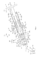
- FIG. 1 is a schematic view of the schematic configuration of a steering system of an embodiment of the invention.
- the steering system is an electric power steering system
- the invention may be applied to a manual steering system.
- a steering system 1 includes a steering shaft 3 that is coupled to a steering member 2, such as a steering wheel, an intermediate shaft 5 that is coupled to the steering shaft 3 via a universal joint 4, a pinion shaft 7 that is coupled to the intermediate shaft 5 via a universal joint 6, and a rack shaft 8 as a steered shaft, which has a rack 8a that meshes with a pinion 7a provided in the vicinity of an end portion of the pinion shaft 7.
- a steered mechanism A1 is constituted by a rack-and-pinion mechanism including the pinion shaft 7 and the rack shaft 8.
- the rack shaft 8 is supported by a housing (not shown) so as to be movable in an axial direction (direction perpendicular to the plane of paper) along a right-and-left direction of a vehicle.
- a housing not shown
- the end portions are coupled to corresponding steered wheels via corresponding tie rods and corresponding knuckle arms.
- the steering shaft 3 includes a first steering shaft 11 and a second steering shaft 12 that are coaxially coupled to each other.
- the first steering shaft 11 includes an upper shaft 13 and a lower shaft 14 that are fitted to each other, for example using spline coupling, so as to be rotatable together and slidable relative to each other in the axial direction.
- Either the upper shaft 13 or the lower shaft 14 constitutes an inner shaft, and the other constitutes a tubular outer shaft.
- the second steering shaft 12 includes an input shaft 15 that is coupled to the lower shaft 14 so as to be rotatable together with the lower shaft 14, an output shaft 16 that is coupled to the intermediate shaft 5 via the universal joint 4 so as to be rotatable together with the intermediate shaft 5, and a torsion bar 17 that couples the input shaft 15 and the output shaft 16 so that the input shaft 15 and the output shaft 16 are rotatable relative to each other.
- the steering shaft 3 is rotatably supported by a steering column 20 via a first bearing 21, a second bearing 22, a third bearing 23, and a fourth bearing 24.
- the steering column 20 is fixed to vehicle-body-side members 18 and 19.
- the steering column 20 includes an outer tube 25 at an upper side and an inner tube 26 at a lower side that are fitted to each other so as to be slidable relative to each other in an axial direction X1, and a housing 27 that is coupled to an axial lower end portion 26L of the inner tube 26.
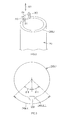
- a cylindrical roller 28 which constitutes a rolling element as a first sliding resistance reducing element that comes into contact with an inner periphery 25a of the outer tube 25 and reduces the sliding resistance between both the tubes 25 and 26, is retained in at least a circumferential lower region 26UL (in the present embodiment, a circumferential lower end portion 26ULL within the circumferential lower region 26UL as shown in FIG. 3 ) of an axial upper end portion 26U of the inner tube 26.
- the cylindrical roller 28 that is the first sliding resistance reducing element is arranged at the circumferential lower end portion 26ULL in the circumferential lower region 26UL.
- a pair of cylindrical rollers may be arranged at bilaterally symmetrical positions so that the points of contact with the inner periphery 25a of the outer tube 25 are arranged within the circumferential lower region 26UL.
- the axial upper end portion 26U of the inner tube 26 is provided with a pair of stays 30 extending upward in the axial direction X1.
- the cylindrical roller 28 is rotatably supported by a support shaft 31 whose two ends are supported by the pair of stays 30.
- the support shaft 31 is arranged along a direction parallel to a line tangent to the inner tube 26.
- a cylindrical roller 29, which constitutes a rolling element as a second sliding resistance reducing element that comes into contact with an outer periphery 26a of the inner tube 26 and reduces the sliding resistance between both the tubes 25 and 26, is retained in at least a circumferential upper region 25LU (in the present embodiment, a circumferential upper end portion 25LUU within the circumferential upper region 25LU as shown in FIG. 5 ) of an axial lower end portion 25L of the outer tube 25.
- the cylindrical roller 29 that is the second sliding resistance reducing element is arranged at the circumferential upper end portion 25LUU in the circumferential upper region 25LU.
- a pair of cylindrical rollers may be arranged at bilaterally symmetrical positions so that the points of contact with the outer periphery 26a of the inner tube 26 are arranged within the circumferential upper region 25LU.
- the axial lower end portion 25L of the outer tube 25 is provided with a pair of stays 32 extending downward in the axial direction X1.
- the cylindrical roller 29 is rotatably supported by a support shaft 33 whose both ends are supported by the pair of stays 32.
- the support shaft 33 is arranged along a direction parallel to a line tangential to the outer tube 25.
- a speed-reducing mechanism 35 is housed within a housing 27.
- the speed-reducing mechanism 35 reduces the speed of the rotation from a steering assisting electric motor 34 to transmit the rotation, whose speed has been reduced, to an output shaft 16.
- a torque sensor 36 which detects a steering torque on the basis of the relative rotation between the input shaft 15 and the output shaft 16, is housed within the housing 27.
- a torque detection result obtained by the torque sensor and a vehicle speed detection result obtained by a vehicle speed sensor (not shown) are input to an electronic control unit (ECU) 37.
- the ECU 37 controls the driving of the electric motor 34 (i.e., performs steering assisting control) so that the electric motor 34 generates a steering assisting force, on the basis of both of the detection results.
- the speed-reducing mechanism 35 includes a driving gear 38 that is coupled to a rotary shaft (not shown) of the electric motor 34 so as to be rotatable together with the rotary shaft, and a driven gear 39 that meshes with the driving gear 38 and rotates together with the output shaft 16.
- the driving gear 38 is constituted by, for example, a worm shaft
- the driven gear 39 is constituted by, for example, a worm wheel.
- the speed-reducing mechanism 35 transmits a steering assisting force generated by the electric motor 34 to the output shaft 16.
- the first bearing 21 is retained by an inner periphery of the axial upper end portion 25U of the upper tube 25, and supports the upper shaft 13 so that the upper shaft 13 is rotatable.
- the second bearing 22 is retained by the housing 27, and supports the input shaft 15 so that the input shaft 15 is rotatable.
- the third bearing 23 and the fourth bearing 24 are retained by the housing 7, and are located on respective sides of the driven gear 39 to support the output shaft 16 so that the output shaft 16 is rotatable.
- the steering column 20 is fixed to the vehicle-body-side members 18 and 19 via an upper bracket 40 at a vehicle rear Y1-side and a lower bracket 41 at a vehicle front Y2-side.
- the upper bracket 40 can be fixed to the outer tube 25 at the upper side of the steering column 20 via a column bracket to be described below.
- the upper bracket 40 is fixed to the vehicle-body-side member 18, using fixing bolts (stud bolts) 42 that protrude downward from the vehicle-body-side member 18, nuts 43 that are screwed to the fixing bolts 42, and capsules 44 that are detachably retained by the upper bracket 40.
- the lower bracket 41 is fixed to the inner tube 26 at the lower side of the steering column 20.
- the lower bracket 41 is fixed to the vehicle-body-side member 19, using a fixing bolt (not shown).
- a fixing bolt (not shown).
- FIG. 6 that is a sectional view taken along line VI-VI in FIG. 1 , the pair of right and left fixing bolts 42 is provided, and the fixing bolts 42 are inserted through the upper bracket 40 and the respective capsules 44.
- the upper bracket 40 and the capsules 44 are held between the vehicle-body-side member 18 and the nuts 43, and thus, the upper bracket 40 is fixed to the vehicle-body-side member 18.
- the upper bracket 40 is separated from the vehicle-body-side member 18 as a resin pin (not shown) provided in each capsule 44 breaks.
- the upper bracket 40 is formed of, for example, sheet metal.
- the upper bracket 40 includes an upper plate 46 having a pair of right and left attachment seats 45, and a main body portion 47 that is fixed to the upper plate 46 and has a groove shape that opens downward.
- the main body portion 47 includes a web 48 as an upper plate that is fixed to a lower surface of the upper plate 46, and a pair of side plates 49 extending from respective ends of the web 48.
- a column bracket 50 with a groove shape that opens upward is fixed to the outer tube 25 at the upper side of the steering column 20.
- the column bracket 50 includes a pair of side plates 51 facing the pair of side plates 49 of the upper bracket 40, respectively.
- a fastening shaft 52 constituted by a bolt extending through the side plates 49 and 51 of the upper bracket 40 and the column bracket 50 is provided.
- a nut 53 screwed to the fastening shaft 52 By rotating a nut 53 screwed to the fastening shaft 52 by the rotational operation of an operating lever 54, both of the side plates 49 and 51 are fastened between the head of the bolt as the fastening shaft 52, and the nut 53 to lock both of the side plates 49 and 51. Accordingly, the position of the steering member 2 after telescopic adjustment is locked, and telescopic locking is achieved.
- an eccentric cam 55 that rotates together with the fastening shaft 52 is provided at an intermediate portion of the fastening shaft 52 in the axial direction.
- the eccentric cam 55 which is rotated together with the fastening shaft 52 by the rotational operation of the operating lever 54, pushes up the outer periphery 26a of the inner tube 26 through an opening 56 formed in the outer tube 25, the backlash between both the tubes 25 and 26 is removed at the time of the telescopic locking.
- the cylindrical roller 28, which is the first sliding resistance reducing element coming into contact with the inner periphery 25a of the outer tube 25, is retained in at least the circumferential lower region 26UL of the axial upper end portion 26U of the inner tube 26, and the cylindrical roller 29, which is the second sliding resistance reducing element coming into contact with the outer periphery 26a of the inner tube 26, is retained in at least the circumferential upper region 25LU of the axial lower end portion 25L of the outer tube 25.
- both the tubes 25 and 26 can be caused to slide smoothly due to the function of the cylindrical roller 28 that is the first sliding resistance reducing element and the function of the cylindrical roller 29 that is the second sliding resistance reducing element. Since the length of fit between both the tubes 25 and 26 can be made as short as possible, size reduction can be achieved while securing a predetermined shock-absorbing stroke.
- both of the first sliding resistance reducing element and the second sliding resistance reducing element are rolling elements, i.e., the cylindrical rollers 28 and 29, respectively
- both the tubes 25 and 26 can be caused to slide more smoothly at the time of shock absorption.
- the cylindrical roller 28 that is the first sliding resistance reducing element and the cylindrical roller 29 that is the second sliding resistance reducing element are respectively arranged at the circumferential lower end portion 26ULL of the axial upper end portion 26U of the inner tube 26 and the circumferential upper end portion 25LUU of the axial lower end portion 25L of the outer tube 25, the circumferential lower end portion 26ULL and the circumferential upper end portion 25LUU being most strongly pressed against the tubes 25 and 26, respectively when the moment M1 that tilts the outer tube 25 at the upper side with respect to the inner tube 26 at the lower side is generated at the time of the secondary collision of the vehicle. Therefore, both the tubes 25 and 26 can be reliably caused to slide smoothly at the time of the shock absorption.
- FIG. 7 shows a steering system 1A of another embodiment of the invention.
- FIG. 8 is a schematic view showing a section of the axial upper end portion 26U of the inner tube 26 of a steering column 20A of the steering system 1A.
- FIG. 9 is a schematic view showing a section of the axial lower end portion of the outer tube of the steering system in FIG. 7 .
- the steering system 1A of the present embodiment is different from the steering system 1 in FIG. 1 in that a cylindrical roller 57 and a cylindrical roller 58 are added. Referring to FIGS.
- the cylindrical roller 57 which constitutes a rolling element as a third sliding resistance reducing element that comes into contact with the inner periphery 25a of the outer tube 25 and reduces the sliding resistance between both the tubes 25 and 26, is retained in at least a circumferential upper region 26UU (in the present embodiment, a circumferential upper end portion 26UUU within the circumferential upper region 26UU as shown in FIG. 8 ) of the axial upper end portion 26U of the inner tube 26.
- the cylindrical roller 58 which constitutes a rolling element as a fourth sliding resistance reducing element that comes into contact with the outer periphery 26a of the inner tube 26 and reduces the sliding resistance between both the tubes 25 and 26, is retained in at least a circumferential lower region 25LL (in the present embodiment, a circumferential lower end portion 25LLL within the circumferential lower region 25LL as shown in FIG. 9 ) of the axial lower end portion 25L of the outer tube 25.
- the same constituent elements as those of the embodiment in FIGS. 1 to 6 are designated by the same reference numerals as the reference numerals of the constituent elements of the embodiment in FIGS. 1 to 6 .
- the cylindrical rollers 57 and 58 are rotatably supported using stays and supporting shafts, as in the case of the cylindrical rollers 28 and 29. According to the present embodiment, the following effects are achieved in addition to achieving the same effects as those of the embodiment in FIG. 1 .
- the cylindrical roller 57 which is the third sliding resistance reducing element coming into contact with the inner periphery 25a of the outer tube 25, is retained in at least the circumferential upper region 26UU of the axial upper end portion 26U of the inner tube 26, and the cylindrical roller 58, which is the fourth sliding resistance reducing element coming into contact with the outer periphery 26a of the inner tube 26, is retained in at least the circumferential lower region 25LL of the axial lower end portion 25L of the outer tube 25.
- both the tubes 25 and 26 can be caused to slide smoothly due to the function of the cylindrical roller 57 that is the third sliding resistance reducing element and the function of the cylindrical roller 58 that is the fourth sliding resistance reducing element.
- both the tubes 25 and 26 can be caused to slide more smoothly at the time of telescopic adjustment in the case where at least one of the third sliding resistance reducing element and the fourth sliding resistance reducing element is a rolling element (in the present embodiment, both of the third sliding resistance reducing element and the fourth sliding resistance reducing element are rolling elements, i.e., the cylindrical rollers 57 and 58, respectively).
- the cylindrical roller 57 that is the third sliding resistance reducing element and the cylindrical roller 58 that is the fourth sliding resistance reducing element are respectively arranged at the circumferential upper end portion 26UUU of the axial upper end portion 26U of the inner tube 26 and the circumferential lower end portion 25LLL of the axial lower end portion 25L of the outer tube 25, the circumferential upper end portion 26UUU and the circumferential lower end portion 25LLL being most strongly pressed against the tubes 25 and 26, respectively when the moment M2 that tilts the outer tube 25 at the upper side with respect to the inner tube 26 at the lower side is generated at the time of telescopic adjustment. Therefore, both the tubes 25 and 26 can be reliably caused to slide smoothly at the time of the telescopic adjustment.
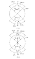
- a pair of cylindrical rollers 28A and 28B may be provided at bilaterally symmetrical positions within the circumferential lower region 26UL of the axial upper end portion 26U, as shown in FIG. 10 .
- a pair of cylindrical rollers 29A and 29B may be provided at bilaterally symmetrical positions within the circumferential upper region 25LU of the axial lower end portion 25L, as shown in FIG. 11 .
- a pair of cylindrical rollers 28A and 28B may be provided at bilaterally symmetrical positions within the circumferential lower region 26UL of the axial upper end portion 26U, as shown in FIG. 12 .
- a pair of cylindrical rollers 57A and 57B may be provided at bilaterally symmetrical positions within the circumferential upper region 26UU of the axial upper end portion 26U, as shown in FIG. 13 .
- a pair of cylindrical rollers 29A and 29B may be provided at bilaterally symmetrical positions within the circumferential upper region 25LU of the axial lower end portion 25L, as shown in FIG. 14 .
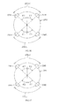
- a pair of cylindrical rollers 58A and 58B may be provided at bilaterally symmetrical positions within the circumferential lower region 25LL of the axial lower end portion 25L, as shown in FIG. 15 .
- three cylindrical rollers rolling elements; sliding resistance reducing elements
- four cylindrical rollers rolling elements; sliding resistance reducing elements
- the cylindrical rollers 28A and 28B as two first sliding resistance reducing elements and the cylindrical rollers 57A and 57B as two third sliding resistance reducing elements may be provided at the axial upper end portion 26U of the inner tube 26.
- the cylindrical rollers 29A and 29B as two second sliding resistance reducing elements and the cylindrical rollers 58A and 58B as two fourth sliding resistance reducing elements may be provided at the axial lower end portion 25L of the outer tube 25.
- the cylindrical roller is used as the rolling element that constitutes each sliding resistance reducing element.
- a barrel-shaped roller may be used instead of the cylindrical roller that comes into rolling contact with the inner periphery 25a of the outer tube 25, or a drum-shaped roller may be used instead of the cylindrical roller that comes into rolling contact with the outer periphery 26a of the inner tube 26.
- a ball may be used instead of the roller.
- a ball 60 which is retained by a retaining hole 59 formed in the inner tube 26 and comes into rolling contact with the inner periphery 25a of the outer tube 25, may be used as the first sliding resistance reducing element or the third sliding resistance reducing element.
- a ball 62 which is retained by a retaining hole 61 formed in the outer tube 25 and comes into rolling contact with the outer periphery 26a of the inner tube 26, may be used as the second sliding resistance reducing element or the fourth sliding resistance reducing element.
- a plain bearing may be configured using a low-friction coating applied to the corresponding tube 25 or 26, instead of using the rolling element.
- a low-friction material that constitutes the low-friction coating for example, fluororesin may be used.
- a portion of the steering column 20 is constituted by the outer tube 25 at the upper side and the inner tube 26 at the lower side.
- a portion of a steering column 120 or 120A may be constituted by an outer tube 125 at a lower side and an inner tube 126 at an upper side as in a steering system 100 of an embodiment in FIG. 20 or a steering system 100A of an embodiment in FIG. 21 .
- a first sliding resistance reducing element that comes into contact with an outer periphery 126a of the inner tube 126 and reduces the sliding resistance between both the tubes 125 and 126, for example, a cylindrical roller 128 as a rolling element is retained in at least a circumferential upper region of an axial upper end portion 125U of the outer tube 125 at the lower side of the steering column 120.
- a second sliding resistance reducing element that comes into contact with an inner periphery 125a of the outer tube 125 and reduces the sliding resistance between both the tubes 125 and126, for example, a cylindrical roller 129 as a rolling element is retained in at least a circumferential lower region of an axial lower end portion 126L of the inner tube 126.
- both the tubes 125 and 126 can be caused to slide smoothly due to the function of the first sliding resistance reducing element, for example, the cylindrical roller 128, and the function of the second sliding resistance reducing element, for example, the cylindrical roller 129. Since the length of fit between both the tubes 125 and 126 can be made as short as possible, size reduction can be achieved while securing a predetermined shock-absorbing stroke.
- At least one of the first sliding resistance reducing element and the second sliding resistance reducing element may be a rolling element such as a roller or a ball, or may use a low-friction coating applied to the corresponding tube.
- a low-friction material that constitutes the low-friction coating for example, fluororesin can be used.
- a third sliding resistance reducing element that comes into contact with the outer periphery 126a of the inner tube 126 at the upper side and reduces the sliding resistance between both the tubes 125 and 126 for example, a cylindrical roller 157 as a rolling element is retained in at least the circumferential lower region of the axial upper end portion 125U of the outer tube 125 at the lower side of the steering column 120A, and a fourth sliding resistance reducing element that comes into contact with the inner periphery 125a of the outer tube 125 and reduces the sliding resistance between both the tubes 125 and 126, for example, a cylindrical roller 158 as a rolling element is retained in at least the circumferential upper region of the axial lower end portion 126U of the inner tube 126.
- both the tubes 125 and 126 can be caused to slide smoothly due to the function of the third sliding resistance reducing element, for example, the cylindrical roller 157, and the function of the fourth sliding resistance reducing element, for example, the cylindrical roller 158.
- At least one of the third sliding resistance reducing element and the fourth sliding resistance reducing element may be a rolling element, such as a roller or a ball, or may use a low-friction coating applied to the corresponding tube.
- a low-friction material that constitutes the low-friction coating for example, fluororesin may be used.
- various modifications may be made within the scope of the invention described in the claims.
Landscapes
- Engineering & Computer Science (AREA)
- Chemical & Material Sciences (AREA)
- Combustion & Propulsion (AREA)
- Transportation (AREA)
- Mechanical Engineering (AREA)
- Steering Controls (AREA)
Abstract
Description
- The present invention relates to a steering system.
- In a telescopic adjustment type steering system that adjusts the position of a steering wheel, which is a steering member, in an axial direction of a steering shaft, an inner shaft and an outer shaft that constitute the steering shaft are fitted to each other so as to be non-rotatable relative to each other and slidable relative to each other in the axial direction, and both the shafts are caused to slide relative to each other in the axial direction so as to perform telescopic adjustment. For example in Japanese Patent Application Publication No.
2006-151011 JP 2006-151011 A - Additionally, for example, in International Publication No.
WO03/031250A1 - In the telescopic adjustment type steering system, a jacket, which supports the steering shaft so that the steering shaft is rotatable, is constituted by an outer tube and an inner tube that are fitted to each other so as to be slidable relative to each other in the axial direction. At the time of a secondary collision in which a driver collides with the steering wheel due to a collision (primary collision) of a vehicle, both the tubes slide relative to each other in the axial direction so as to absorb shock energy.
- However, since the steering wheel tends to be pushed upward at the time of the secondary collision, a twist is apt to be caused between the outer tube and the inner tube. If the twist is caused, the sliding resistance between both the tubes may become large and both the tubes may not be able to smoothly slide relative to each other when shock is absorbed. In the case where the length of fit between both the tubes is set to be long in order to reduce the twist between both the tubes when shock is absorbed, it is difficult to reduce the size of the steering system in the axial direction while securing a required shock-absorbing stroke.
- An object of the invention is to provide a small-sized steering system while securing a required shock-absorbing stroke.
- A steering system according to an aspect of the invention includes an outer tube at an upper side and an inner tube at a lower side that support a steering shaft so that the steering shaft is rotatable, the outer tube and the inner tube sliding relative to each other in an axial direction when shock is absorbed, and the steering shaft having one end to which a steering member is coupled; a first sliding resistance reducing element that is retained in at least a circumferential lower region of an axial upper end portion of the inner tube, comes into contact with an inner periphery of the outer tube, and reduces sliding resistance between the outer tube and the inner tube; and a second sliding resistance reducing element that is retained in at least a circumferential upper region of an axial lower end portion of the outer tube, comes into contact with an outer periphery of the inner tube, and reduces the sliding resistance between the outer tube and the inner tube.
- In the steering system according to the above-described aspect, the first sliding resistance reducing element, which comes into contact with the inner periphery of the outer tube at the upper side, is retained in at least the circumferential lower region of the axial upper end portion of the inner tube at the lower side, and the second sliding resistance reducing element, which comes into contact with the outer periphery of the inner tube, is retained in at least the circumferential upper region of the axial lower end portion of the outer tube. Accordingly, even when a moment that tilts the outer tube with respect to the inner tube is generated so as to push up the axial upper end portion of the outer tube at the upper side at the time of a secondary collision of a vehicle, the outer tube and the inner tube can be caused to slide relative to each other smoothly due to the function of the first sliding resistance reducing element and the function of the second sliding resistance reducing element. Since the length of fit between the outer tube and the inner tube can be made as short as possible, size reduction can be achieved while securing a predetermined shock-absorbing stroke.
- The steering system according to the above-described aspect may further include a third sliding resistance reducing element that is retained in at least a circumferential upper region of the axial upper end portion of the inner tube, comes into contact with the inner periphery of the outer tube, and reduces the sliding resistance between the outer tube and the inner tube; and a fourth sliding resistance reducing element that is retained in at least a circumferential lower region of the axial lower end portion of the outer tube, comes into contact with the outer periphery of the inner tube, and reduces the sliding resistance between the outer tube and the inner tube.
- In the steering system according to the above-described aspect, the third sliding resistance reducing element, which comes into contact with the inner periphery of the outer tube at the upper side, is retained in at least the circumferential upper region of the axial upper end portion of the inner tube at the lower side, and the fourth sliding resistance reducing element, which comes into contact with the outer periphery of the inner tube, is retained in at least the circumferential lower region of the axial lower end portion of the outer tube. Accordingly, even when a moment that tilts the outer tube with respect to the inner tube is generated so that the axial upper end portion of the outer tube at the upper side is pushed downward by the weight of the steering member, or the like at the time of telescopic adjustment, the outer tube and the inner tube can be caused to slide relative to each other smoothly due to the function of the third sliding resistance reducing element and the function of the fourth sliding resistance reducing element.
- A steering system according to another aspect of the invention includes an inner tube at an upper side and an outer tube at a lower side that support a steering shaft so that the steering shaft is rotatable, the inner tube and the outer tube sliding relative to each other in an axial direction when shock is absorbed, and the steering shaft having one end to which a steering member is coupled; a first sliding resistance reducing element that is retained in at least a circumferential upper region of an axial upper end portion of the outer tube, comes into contact with an outer periphery of the inner tube, and reduces sliding resistance between the inner tube and the outer tube; and a second sliding resistance reducing element that is retained in at least a circumferential lower region of an axial lower end portion of the inner tube, comes into contact with an inner periphery of the outer tube, and reduces the sliding resistance between the inner tube and the outer tube.
- In the steering system according to the above-described aspect, the first sliding resistance reducing element, which comes into contact with the outer periphery of the inner tube at the upper side, is retained in at least the circumferential upper region of the axial upper end portion of the outer tube at the lower side, and the second sliding resistance reducing element, which comes into contact with the inner periphery of the outer tube, is retained in at least the circumferential lower region of the axial lower end portion of the inner tube. Accordingly, even when a moment that tilts the inner tube with respect to the outer tube is generated so as to push up the axial upper end portion of the inner tube at the upper side at the time of the secondary collision of the vehicle, the inner tube and the outer tube can be caused to slide relative to each other smoothly due to the function of the first sliding resistance reducing element and the function of the second sliding resistance reducing element. Since the length of fit between the inner tube and the outer tube can be made as short as possible, size reduction can be achieved while securing a predetermined shock-absorbing stroke.
- The steering system according to the above-described aspect may further include a third sliding resistance reducing element that is retained in at least a circumferential lower region of the axial upper end portion of the outer tube, comes into contact with the outer periphery of the inner tube, and reduces the sliding resistance between the inner tube and the outer tube; and a fourth sliding resistance reducing element that is retained in at least a circumferential upper region of the axial lower end portion of the inner tube, comes into contact with the inner periphery of the outer tube, and reduces the sliding resistance between the inner tube and the outer tube.
- In the steering system according to the above-described aspect, the third sliding resistance reducing element, which comes into contact with the outer periphery of the inner tube at the upper side, is retained in at least the circumferential lower region of the axial upper end portion of the outer tube at the lower side, and the fourth sliding resistance reducing element, which comes into contact with the inner periphery of the outer tube, is retained in at least the circumferential upper region of the axial lower end portion of the inner tube. Accordingly, even when a moment that tilts the inner tube with respect to the outer tube is generated so that the axial upper end portion of the inner tube at the upper side is pushed downward by the weight of the steering member, or the like at the time of telescopic adjustment, the inner tube and the outer tube can be caused to slide relative to each other smoothly due to the function of the third sliding resistance reducing element and the function of the fourth sliding resistance reducing element.
- In the steering system according to each of the above-described aspects, at least one of the first sliding resistance reducing element and the second sliding resistance reducing element may be a rolling element.
- In the steering system according to each of the above-described aspects, at least one of the first sliding resistance reducing element and the second sliding resistance reducing element is a rolling element, and therefore, the outer tube and the inner tube can be caused to slide relative to each other smoothly when shock is absorbed.
- In the steering system according to each of the above-described aspects, at least one of the third sliding resistance reducing element and the fourth sliding resistance reducing element may be a rolling element.
- In the steering system according to each of the above-described aspects, at least one of the third sliding resistance reducing element and the fourth sliding resistance reducing element is a rolling element, and therefore, the outer tube and the inner tube can be caused to slide relative to each other smoothly at the time of telescopic adjustment.
- The foregoing and further features and advantages of the invention will become apparent from the following description of example embodiments with reference to the accompanying drawings, wherein like numerals are used to represent like elements and wherein:
-
FIG. 1 is a schematic sectional view showing a steering system according to an embodiment of the invention; -
FIG. 2 is a schematic perspective view showing an axial upper end portion of an inner tube of a steering column of the steering system inFIG. 1 , and portions around the axial upper end portion of the inner tube; -
FIG. 3 is a schematic view showing a section of the axial upper end portion of the inner tube inFIG. 2 ; -
FIG. 4 is a schematic perspective view showing an axial lower end portion of an outer tube of the steering column of the steering system inFIG. 1 , and portions around the axial lower end portion of the outer tube; -
FIG. 5 is a schematic view showing a section of the axial lower end portion of the outer tube inFIG. 4 ; -
FIG. 6 is a schematic sectional view of main portions of the steering system inFIG. 1 ,FIG. 6 showing a section taken along a line VI-VI inFIG. 1 ; -
FIG. 7 is a schematic sectional view showing a steering system according to another embodiment of the invention; -
FIG. 8 is a schematic view showing a section of an axial upper end portion of an inner tube of the steering system inFIG. 7 ; -
FIG. 9 is a schematic view showing a section of an axial lower end portion of an outer tube of the steering system inFIG. 7 ; -
FIG. 10 is a schematic view showing a section of an axial upper end portion of an inner tube in yet another embodiment of the invention,FIG. 10 showing a modification of the embodiment inFIG. 3 ; -
FIG. 11 is a schematic view showing a section of an axial lower end portion of an outer tube in yet another embodiment of the invention,FIG. 11 showing a modification of the embodiment inFIG. 5 ; -
FIG. 12 is a schematic view showing a section of an axial upper end portion of an inner tube in yet another embodiment of the invention,FIG. 12 showing a modification of the embodiment inFIG. 8 ; -
FIG. 13 is a schematic view showing a section of an axial upper end portion of an inner tube in yet another embodiment of the invention,FIG. 13 showing a modification of the embodiment inFIG. 8 ; -
FIG. 14 is a schematic view showing a section of an axial lower end portion of an outer tube in yet another embodiment of the invention,FIG. 14 showing a modification of the embodiment inFIG. 9 ; -
FIG. 15 is a schematic view showing a section of an axial lower end portion of an outer tube in yet another embodiment of the invention,FIG. 15 showing a modification of the embodiment inFIG. 9 ; -
FIG. 16 is a schematic view showing a section of an axial upper end portion of an inner tube in yet another embodiment of the invention,FIG. 16 showing a modification of the embodiment inFIG. 8 ; -
FIG. 17 is a schematic view showing a section of an axial lower end portion of an outer tube in yet another embodiment of the invention,FIG. 17 showing a modification of the embodiment inFIG. 9 : -
FIG. 18 is a schematic sectional view showing a steering column in yet another embodiment of the invention,FIG. 18 showing an example in which a ball is used as a rolling element that comes rolling contact with an outer tube; -
FIG. 19 is a schematic sectional view showing a steering column in yet another embodiment of the invention,FIG. 19 showing an example in which a ball is used as a rolling element that comes rolling contact with an inner tube; -
FIG. 20 is a schematic sectional view of main portions of a steering system in yet another embodiment of the invention; and -
FIG. 21 is a schematic sectional view of main portions of a steering system in yet another embodiment of the invention,FIG. 21 showing a modification of the embodiment inFIG. 20 . - Hereinafter, embodiments of the invention will be described with reference to the accompanying drawings.
FIG. 1 is a schematic view of the schematic configuration of a steering system of an embodiment of the invention. Although the present embodiment will be described according to a case where the steering system is an electric power steering system, the invention may be applied to a manual steering system. Referring toFIG. 1 , a steering system 1 includes asteering shaft 3 that is coupled to asteering member 2, such as a steering wheel, anintermediate shaft 5 that is coupled to thesteering shaft 3 via auniversal joint 4, apinion shaft 7 that is coupled to theintermediate shaft 5 via auniversal joint 6, and arack shaft 8 as a steered shaft, which has a rack 8a that meshes with a pinion 7a provided in the vicinity of an end portion of thepinion shaft 7. - A steered mechanism A1 is constituted by a rack-and-pinion mechanism including the
pinion shaft 7 and therack shaft 8. Therack shaft 8 is supported by a housing (not shown) so as to be movable in an axial direction (direction perpendicular to the plane of paper) along a right-and-left direction of a vehicle. Although respective end portions of therack shaft 8 are not shown, the end portions are coupled to corresponding steered wheels via corresponding tie rods and corresponding knuckle arms. - The steering
shaft 3 includes afirst steering shaft 11 and asecond steering shaft 12 that are coaxially coupled to each other. Thefirst steering shaft 11 includes anupper shaft 13 and alower shaft 14 that are fitted to each other, for example using spline coupling, so as to be rotatable together and slidable relative to each other in the axial direction. Either theupper shaft 13 or thelower shaft 14 constitutes an inner shaft, and the other constitutes a tubular outer shaft. - The
second steering shaft 12 includes aninput shaft 15 that is coupled to thelower shaft 14 so as to be rotatable together with thelower shaft 14, anoutput shaft 16 that is coupled to theintermediate shaft 5 via theuniversal joint 4 so as to be rotatable together with theintermediate shaft 5, and atorsion bar 17 that couples theinput shaft 15 and theoutput shaft 16 so that theinput shaft 15 and theoutput shaft 16 are rotatable relative to each other. The steeringshaft 3 is rotatably supported by asteering column 20 via afirst bearing 21, asecond bearing 22, athird bearing 23, and afourth bearing 24. Thesteering column 20 is fixed to vehicle-body-side members - The
steering column 20 includes anouter tube 25 at an upper side and aninner tube 26 at a lower side that are fitted to each other so as to be slidable relative to each other in an axial direction X1, and ahousing 27 that is coupled to an axiallower end portion 26L of theinner tube 26. Referring toFIGS. 1 ,2, and 3 , acylindrical roller 28, which constitutes a rolling element as a first sliding resistance reducing element that comes into contact with aninner periphery 25a of theouter tube 25 and reduces the sliding resistance between both thetubes FIG. 3 ) of an axialupper end portion 26U of theinner tube 26. - As shown in
FIG. 3 , in the axialupper end portion 26U of theinner tube 26, the circumferential lower region 26UL is a region within a range composed of right and left ranges located on right and left sides of a line extending downward from a center, each of the right and left ranges corresponding to a central angle θ1 (θ1 = 45 degrees). In the present embodiment, thecylindrical roller 28 that is the first sliding resistance reducing element is arranged at the circumferential lower end portion 26ULL in the circumferential lower region 26UL. Instead of this configuration, however, a pair of cylindrical rollers may be arranged at bilaterally symmetrical positions so that the points of contact with theinner periphery 25a of theouter tube 25 are arranged within the circumferential lower region 26UL. - As shown in
FIG. 2 , the axialupper end portion 26U of theinner tube 26 is provided with a pair ofstays 30 extending upward in the axial direction X1. Thecylindrical roller 28 is rotatably supported by asupport shaft 31 whose two ends are supported by the pair of stays 30. Thesupport shaft 31 is arranged along a direction parallel to a line tangent to theinner tube 26. Referring toFIGS. 1 ,4, and 5 , acylindrical roller 29, which constitutes a rolling element as a second sliding resistance reducing element that comes into contact with anouter periphery 26a of theinner tube 26 and reduces the sliding resistance between both thetubes FIG. 5 ) of an axiallower end portion 25L of theouter tube 25. - As shown in
FIG. 5 , in the axiallower end portion 25L of theouter tube 25, the circumferential upper region 25LU is a region within a range composed of right and left ranges located on right and left sides of a line extending upward from a center, each of the right and left ranges corresponding to a central angle θ2 (θ2 = 45 degrees). In the present embodiment, thecylindrical roller 29 that is the second sliding resistance reducing element is arranged at the circumferential upper end portion 25LUU in the circumferential upper region 25LU. Instead of this configuration, however, a pair of cylindrical rollers may be arranged at bilaterally symmetrical positions so that the points of contact with theouter periphery 26a of theinner tube 26 are arranged within the circumferential upper region 25LU. - As shown in
FIG. 4 , the axiallower end portion 25L of theouter tube 25 is provided with a pair ofstays 32 extending downward in the axial direction X1. Thecylindrical roller 29 is rotatably supported by asupport shaft 33 whose both ends are supported by the pair of stays 32. Thesupport shaft 33 is arranged along a direction parallel to a line tangential to theouter tube 25. - Referring back to
FIG. 1 , a speed-reducingmechanism 35 is housed within ahousing 27. The speed-reducingmechanism 35 reduces the speed of the rotation from a steering assistingelectric motor 34 to transmit the rotation, whose speed has been reduced, to anoutput shaft 16. Atorque sensor 36, which detects a steering torque on the basis of the relative rotation between theinput shaft 15 and theoutput shaft 16, is housed within thehousing 27. A torque detection result obtained by the torque sensor and a vehicle speed detection result obtained by a vehicle speed sensor (not shown) are input to an electronic control unit (ECU) 37. TheECU 37 controls the driving of the electric motor 34 (i.e., performs steering assisting control) so that theelectric motor 34 generates a steering assisting force, on the basis of both of the detection results. - The speed-reducing
mechanism 35 includes adriving gear 38 that is coupled to a rotary shaft (not shown) of theelectric motor 34 so as to be rotatable together with the rotary shaft, and a drivengear 39 that meshes with thedriving gear 38 and rotates together with theoutput shaft 16. Thedriving gear 38 is constituted by, for example, a worm shaft, and the drivengear 39 is constituted by, for example, a worm wheel. The speed-reducingmechanism 35 transmits a steering assisting force generated by theelectric motor 34 to theoutput shaft 16. - The
first bearing 21 is retained by an inner periphery of the axialupper end portion 25U of theupper tube 25, and supports theupper shaft 13 so that theupper shaft 13 is rotatable. Thesecond bearing 22 is retained by thehousing 27, and supports theinput shaft 15 so that theinput shaft 15 is rotatable. Thethird bearing 23 and thefourth bearing 24 are retained by thehousing 7, and are located on respective sides of the drivengear 39 to support theoutput shaft 16 so that theoutput shaft 16 is rotatable. Thesteering column 20 is fixed to the vehicle-body-side members upper bracket 40 at a vehicle rear Y1-side and alower bracket 41 at a vehicle front Y2-side. Theupper bracket 40 can be fixed to theouter tube 25 at the upper side of thesteering column 20 via a column bracket to be described below. Theupper bracket 40 is fixed to the vehicle-body-side member 18, using fixing bolts (stud bolts) 42 that protrude downward from the vehicle-body-side member 18,nuts 43 that are screwed to the fixingbolts 42, andcapsules 44 that are detachably retained by theupper bracket 40. - The
lower bracket 41 is fixed to theinner tube 26 at the lower side of thesteering column 20. Thelower bracket 41 is fixed to the vehicle-body-side member 19, using a fixing bolt (not shown). With reference toFIG. 6 that is a sectional view taken along line VI-VI inFIG. 1 , the pair of right and left fixingbolts 42 is provided, and the fixingbolts 42 are inserted through theupper bracket 40 and therespective capsules 44. By fastening the nuts 43 to the respective fixingbolts 42, theupper bracket 40 and thecapsules 44 are held between the vehicle-body-side member 18 and the nuts 43, and thus, theupper bracket 40 is fixed to the vehicle-body-side member 18. At the time of a secondary collision, theupper bracket 40 is separated from the vehicle-body-side member 18 as a resin pin (not shown) provided in eachcapsule 44 breaks. - The
upper bracket 40 is formed of, for example, sheet metal. Theupper bracket 40 includes anupper plate 46 having a pair of right and left attachment seats 45, and amain body portion 47 that is fixed to theupper plate 46 and has a groove shape that opens downward. Themain body portion 47 includes aweb 48 as an upper plate that is fixed to a lower surface of theupper plate 46, and a pair ofside plates 49 extending from respective ends of theweb 48. On the other hand, a column bracket 50 with a groove shape that opens upward is fixed to theouter tube 25 at the upper side of thesteering column 20. The column bracket 50 includes a pair ofside plates 51 facing the pair ofside plates 49 of theupper bracket 40, respectively. - A
fastening shaft 52 constituted by a bolt extending through theside plates upper bracket 40 and the column bracket 50 is provided. By rotating anut 53 screwed to thefastening shaft 52 by the rotational operation of an operatinglever 54, both of theside plates fastening shaft 52, and thenut 53 to lock both of theside plates member 2 after telescopic adjustment is locked, and telescopic locking is achieved. - On the other hand, an
eccentric cam 55 that rotates together with thefastening shaft 52 is provided at an intermediate portion of thefastening shaft 52 in the axial direction. As theeccentric cam 55, which is rotated together with thefastening shaft 52 by the rotational operation of the operatinglever 54, pushes up theouter periphery 26a of theinner tube 26 through anopening 56 formed in theouter tube 25, the backlash between both thetubes - According to the present embodiment, the
cylindrical roller 28, which is the first sliding resistance reducing element coming into contact with theinner periphery 25a of theouter tube 25, is retained in at least the circumferential lower region 26UL of the axialupper end portion 26U of theinner tube 26, and thecylindrical roller 29, which is the second sliding resistance reducing element coming into contact with theouter periphery 26a of theinner tube 26, is retained in at least the circumferential upper region 25LU of the axiallower end portion 25L of theouter tube 25. - Even when the steering
member 2 receives a force F1 (refer toFIG. 1 ) toward the vehicle front Y2 at the secondary collision of the vehicle, and thus, a moment M1 (refer toFIG. 1 ) that tilts theouter tube 25 with respect to theinner tube 26 is generated so as to push up the axialupper end portion 25U of theouter tube 25 at the upper side, both thetubes cylindrical roller 28 that is the first sliding resistance reducing element and the function of thecylindrical roller 29 that is the second sliding resistance reducing element. Since the length of fit between both thetubes - In addition, in the case where at least one of the first sliding resistance reducing element and the second sliding resistance reducing element is a rolling element (in the present embodiment, both of the first sliding resistance reducing element and the second sliding resistance reducing element are rolling elements, i.e., the
cylindrical rollers tubes cylindrical roller 28 that is the first sliding resistance reducing element and thecylindrical roller 29 that is the second sliding resistance reducing element are respectively arranged at the circumferential lower end portion 26ULL of the axialupper end portion 26U of theinner tube 26 and the circumferential upper end portion 25LUU of the axiallower end portion 25L of theouter tube 25, the circumferential lower end portion 26ULL and the circumferential upper end portion 25LUU being most strongly pressed against thetubes outer tube 25 at the upper side with respect to theinner tube 26 at the lower side is generated at the time of the secondary collision of the vehicle. Therefore, both thetubes -
FIG. 7 shows asteering system 1A of another embodiment of the invention.FIG. 8 is a schematic view showing a section of the axialupper end portion 26U of theinner tube 26 of asteering column 20A of thesteering system 1A.FIG. 9 is a schematic view showing a section of the axial lower end portion of the outer tube of the steering system inFIG. 7 . Thesteering system 1A of the present embodiment is different from the steering system 1 inFIG. 1 in that acylindrical roller 57 and acylindrical roller 58 are added. Referring toFIGS. 7 and8 , thecylindrical roller 57, which constitutes a rolling element as a third sliding resistance reducing element that comes into contact with theinner periphery 25a of theouter tube 25 and reduces the sliding resistance between both thetubes FIG. 8 ) of the axialupper end portion 26U of theinner tube 26. - Referring to
FIGS. 7 and9 , thecylindrical roller 58, which constitutes a rolling element as a fourth sliding resistance reducing element that comes into contact with theouter periphery 26a of theinner tube 26 and reduces the sliding resistance between both thetubes FIG. 9 ) of the axiallower end portion 25L of theouter tube 25. - With regard to the constituent elements of the present embodiment, the same constituent elements as those of the embodiment in
FIGS. 1 to 6 are designated by the same reference numerals as the reference numerals of the constituent elements of the embodiment inFIGS. 1 to 6 . In addition, thecylindrical rollers cylindrical rollers FIG. 1 . That is, thecylindrical roller 57, which is the third sliding resistance reducing element coming into contact with theinner periphery 25a of theouter tube 25, is retained in at least the circumferential upper region 26UU of the axialupper end portion 26U of theinner tube 26, and thecylindrical roller 58, which is the fourth sliding resistance reducing element coming into contact with theouter periphery 26a of theinner tube 26, is retained in at least the circumferential lower region 25LL of the axiallower end portion 25L of theouter tube 25. Accordingly, even when a moment M2 that tilts theouter tube 25 with respect to theinner tube 26 is generated so that the axialupper end portion 25U of theouter tube 25 at the upper side is pushed downward by the weight G1 of the steeringmember 2, or the like at the time of telescopic adjustment, both thetubes cylindrical roller 57 that is the third sliding resistance reducing element and the function of thecylindrical roller 58 that is the fourth sliding resistance reducing element. - In addition, both the
tubes cylindrical rollers cylindrical roller 57 that is the third sliding resistance reducing element and thecylindrical roller 58 that is the fourth sliding resistance reducing element are respectively arranged at the circumferential upper end portion 26UUU of the axialupper end portion 26U of theinner tube 26 and the circumferential lower end portion 25LLL of the axiallower end portion 25L of theouter tube 25, the circumferential upper end portion 26UUU and the circumferential lower end portion 25LLL being most strongly pressed against thetubes outer tube 25 at the upper side with respect to theinner tube 26 at the lower side is generated at the time of telescopic adjustment. Therefore, both thetubes - The invention is not limited to the above-described embodiments. For example, instead of the single
cylindrical roller 28 that is the first sliding resistance reducing element arranged at the circumferential lower end portion 26ULL of the axialupper end portion 26U of theinner tube 26 inFIG. 3 , a pair ofcylindrical rollers upper end portion 26U, as shown inFIG. 10 . - Instead of the single
cylindrical roller 29 that is the second sliding resistance reducing element arranged at the circumferential upper end portion 25LUU of the axiallower end portion 25L of theouter tube 25 inFIG. 5 , a pair ofcylindrical rollers lower end portion 25L, as shown inFIG. 11 . Instead of the singlecylindrical roller 28 that is the first sliding resistance reducing element arranged at the circumferential lower end portion 26ULL of the axialupper end portion 26U of theinner tube 26 inFIG. 8 , a pair ofcylindrical rollers upper end portion 26U, as shown inFIG. 12 . - Instead of the single
cylindrical roller 57 that is the third sliding resistance reducing element arranged at the circumferential upper end portion 26UUU of the axialupper end portion 26U of theinner tube 26 inFIG. 8 , a pair ofcylindrical rollers upper end portion 26U, as shown inFIG. 13 . Instead of the singlecylindrical roller 29 that is the second sliding resistance reducing element arranged at the circumferential upper end portion 25LUU of the axiallower end portion 25L of theouter tube 25 inFIG. 9 , a pair ofcylindrical rollers lower end portion 25L, as shown inFIG. 14 . - Instead of the single
cylindrical roller 58 that is the fourth sliding resistance reducing element arranged at the circumferential lower end portion 25LLL of the axiallower end portion 25L of theouter tube 25 inFIG. 9 , a pair ofcylindrical rollers lower end portion 25L, as shown inFIG. 15 . In each of the modified embodiments inFIGS. 12 to 15 , three cylindrical rollers (rolling elements; sliding resistance reducing elements) are arranged in the circumferential direction. On the other hand, it is also conceivable to use four cylindrical rollers (rolling elements; sliding resistance reducing elements) arranged in the circumferential direction. For example, as shown inFIG. 16 showing a modification of the embodiment inFIG. 8 , thecylindrical rollers cylindrical rollers upper end portion 26U of theinner tube 26. - As shown in
FIG. 17 showing a modification of the embodiment inFIG. 9 , thecylindrical rollers cylindrical rollers lower end portion 25L of theouter tube 25. In each of the above-described embodiments, the cylindrical roller is used as the rolling element that constitutes each sliding resistance reducing element. However, a barrel-shaped roller may be used instead of the cylindrical roller that comes into rolling contact with theinner periphery 25a of theouter tube 25, or a drum-shaped roller may be used instead of the cylindrical roller that comes into rolling contact with theouter periphery 26a of theinner tube 26. - In each of the above-described embodiments, as the rolling element that constitutes each sliding resistance reducing element, a ball may be used instead of the roller. For example, as shown in
FIG. 18 , aball 60, which is retained by a retaininghole 59 formed in theinner tube 26 and comes into rolling contact with theinner periphery 25a of theouter tube 25, may be used as the first sliding resistance reducing element or the third sliding resistance reducing element. As shown inFIG. 19 , aball 62, which is retained by a retaininghole 61 formed in theouter tube 25 and comes into rolling contact with theouter periphery 26a of theinner tube 26, may be used as the second sliding resistance reducing element or the fourth sliding resistance reducing element. - As the sliding resistance reducing element, a plain bearing may be configured using a low-friction coating applied to the corresponding
tube FIGS. 1 to 19 , a portion of thesteering column 20 is constituted by theouter tube 25 at the upper side and theinner tube 26 at the lower side. Instead of this configuration, however, a portion of asteering column outer tube 125 at a lower side and aninner tube 126 at an upper side as in asteering system 100 of an embodiment inFIG. 20 or asteering system 100A of an embodiment inFIG. 21 . With regard to the constituent elements of the embodiments inFIGS. 20 and21 , the same constituent elements as the constituent elements of the embodiments inFIGS. 1 to 19 are designated by the same reference numerals as the reference numerals of the constituent elements of the embodiments inFIGS. 1 to 19 . - In the
steering system 100 of the embodiment inFIG. 20 , a first sliding resistance reducing element that comes into contact with anouter periphery 126a of theinner tube 126 and reduces the sliding resistance between both thetubes cylindrical roller 128 as a rolling element is retained in at least a circumferential upper region of an axialupper end portion 125U of theouter tube 125 at the lower side of thesteering column 120. In addition, a second sliding resistance reducing element that comes into contact with aninner periphery 125a of theouter tube 125 and reduces the sliding resistance between both thetubes 125 and126, for example, acylindrical roller 129 as a rolling element is retained in at least a circumferential lower region of an axiallower end portion 126L of theinner tube 126. - According to the embodiment in
FIG. 20 , even when a moment M1 that tilts theinner tube 126 with respect to theouter tube 125 is generated so as to push up the axialupper end portion 126U of theinner tube 126 at the upper side at the time of the secondary collision of the vehicle, both thetubes cylindrical roller 128, and the function of the second sliding resistance reducing element, for example, thecylindrical roller 129. Since the length of fit between both thetubes - In the present embodiment, at least one of the first sliding resistance reducing element and the second sliding resistance reducing element may be a rolling element such as a roller or a ball, or may use a low-friction coating applied to the corresponding tube. As a low-friction material that constitutes the low-friction coating, for example, fluororesin can be used. Next, configurations in the
steering system 100A of the embodiment inFIG. 21 , which are additionally provided as compared to thesteering system 100 of the embodiment inFIG. 20 , will be described. In thesteering system 100A of the embodiment inFIG. 21 , a third sliding resistance reducing element that comes into contact with theouter periphery 126a of theinner tube 126 at the upper side and reduces the sliding resistance between both thetubes cylindrical roller 157 as a rolling element is retained in at least the circumferential lower region of the axialupper end portion 125U of theouter tube 125 at the lower side of thesteering column 120A, and a fourth sliding resistance reducing element that comes into contact with theinner periphery 125a of theouter tube 125 and reduces the sliding resistance between both thetubes cylindrical roller 158 as a rolling element is retained in at least the circumferential upper region of the axiallower end portion 126U of theinner tube 126. - According to the embodiment in
FIG. 21 , the following effects are achieved in addition to achieving the same effective effects as those of the embodiment inFIG. 20 . Even when a moment M2 that tilts theinner tube 126 with respect to theouter tube 125 is generated so that the axialupper end portion 126L of theinner tube 126 at the upper side is pushed downward by the weight of the steeringmember 2, or the like at the time of telescopic adjustment, both thetubes cylindrical roller 157, and the function of the fourth sliding resistance reducing element, for example, thecylindrical roller 158. - In the present embodiment, at least one of the third sliding resistance reducing element and the fourth sliding resistance reducing element may be a rolling element, such as a roller or a ball, or may use a low-friction coating applied to the corresponding tube. As a low-friction material that constitutes the low-friction coating, for example, fluororesin may be used. In addition, various modifications may be made within the scope of the invention described in the claims.
Claims (6)
- A steering system comprising:an outer tube at an upper side and an inner tube at a lower side that support a steering shaft so that the steering shaft is rotatable, the outer tube and the inner tube sliding relative to each other in an axial direction when shock is absorbed, and the steering shaft having one end to which a steering member is coupled;a first sliding resistance reducing element that is retained in at least a circumferential lower region of an axial upper end portion of the inner tube, comes into contact with an inner periphery of the outer tube, and reduces sliding resistance between the outer tube and the inner tube; anda second sliding resistance reducing element that is retained in at least a circumferential upper region of an axial lower end portion of the outer tube, comes into contact with an outer periphery of the inner tube, and reduces the sliding resistance between the outer tube and the inner tube.
- The steering system according to claim 1, further comprising:a third sliding resistance reducing element that is retained in at least a circumferential upper region of the axial upper end portion of the inner tube, comes into contact with the inner periphery of the outer tube, and reduces the sliding resistance between the outer tube and the inner tube; anda fourth sliding resistance reducing element that is retained in at least a circumferential lower region of the axial lower end portion of the outer tube, comes into contact with the outer periphery of the inner tube, and reduces the sliding resistance between the outer tube and the inner tube.
- A steering system comprising:an inner tube at an upper side and an outer tube at a lower side that support a steering shaft so that the steering shaft is rotatable, the inner tube and the outer tube sliding relative to each other in an axial direction when shock is absorbed, and the steering shaft having one end to which a steering member is coupled;a first sliding resistance reducing element that is retained in at least a circumferential upper region of an axial upper end portion of the outer tube, comes into contact with an outer periphery of the inner tube, and reduces sliding resistance between the inner tube and the outer tube; anda second sliding resistance reducing element that is retained in at least a circumferential lower region of an axial lower end portion of the inner tube, comes into contact with an inner periphery of the outer tube, and reduces the sliding resistance between the inner tube and the outer tube.
- The steering system according to claim 3, further comprising:a third sliding resistance reducing element that is retained in at least a circumferential lower region of the axial upper end portion of the outer tube, comes into contact with the outer periphery of the inner tube, and reduces the sliding resistance between the inner tube and the outer tube; anda fourth sliding resistance reducing element that is retained in at least a circumferential upper region of the axial lower end portion of the inner tube, comes into contact with the inner periphery of the outer tube, and reduces the sliding resistance between the inner tube and the outer tube.
- The steering system according to any one of claims 1 to 4, wherein at least one of the first sliding resistance reducing element and the second sliding resistance reducing element is a rolling element.
- The steering system according to claim 2 or 4, wherein at least one of the third sliding resistance reducing element and the fourth sliding resistance reducing element is a rolling element.
Applications Claiming Priority (1)
| Application Number | Priority Date | Filing Date | Title |
|---|---|---|---|
| JP2012255417A JP2014101070A (en) | 2012-11-21 | 2012-11-21 | Steering device |
Publications (2)
| Publication Number | Publication Date |
|---|---|
| EP2735494A2 true EP2735494A2 (en) | 2014-05-28 |
| EP2735494A3 EP2735494A3 (en) | 2015-12-02 |
Family
ID=49585306
Family Applications (1)
| Application Number | Title | Priority Date | Filing Date |
|---|---|---|---|
| EP13193048.9A Withdrawn EP2735494A3 (en) | 2012-11-21 | 2013-11-15 | Steering system |
Country Status (4)
| Country | Link |
|---|---|
| US (1) | US8935968B2 (en) |
| EP (1) | EP2735494A3 (en) |
| JP (1) | JP2014101070A (en) |
| CN (1) | CN103832460A (en) |
Cited By (2)
| Publication number | Priority date | Publication date | Assignee | Title |
|---|---|---|---|---|
| EP3187392A1 (en) * | 2015-10-23 | 2017-07-05 | FUJI KIKO Co., Ltd. | Steering column device |
| EP3257725A4 (en) * | 2015-10-21 | 2018-06-13 | NSK Ltd. | Telescopic steering column and steering device |
Families Citing this family (28)
| Publication number | Priority date | Publication date | Assignee | Title |
|---|---|---|---|---|
| US9616914B2 (en) | 2014-02-20 | 2017-04-11 | Steering Solutions Ip Holding Corporation | Telescope and adaptive energy absorption system |
| US9663136B2 (en) * | 2014-02-20 | 2017-05-30 | Steering Solutions Ip Holding Corporation | Steering column having anti-rotation feature |
| US9499190B2 (en) | 2014-03-06 | 2016-11-22 | Steering Solutions Ip Holding Corporation | Adjustable steering column assembly having self-de-lashing power-rake mechanism |
| JP6598001B2 (en) * | 2014-12-12 | 2019-10-30 | 株式会社ジェイテクト | Steering device |
| US9663134B2 (en) * | 2014-12-12 | 2017-05-30 | Jtekt Corporation | Steering system |
| US9522694B2 (en) | 2015-02-27 | 2016-12-20 | Steering Solutions Ip Holding Corporation | Radial telescope bushing for steering column |
| DE102015002889B3 (en) | 2015-03-09 | 2016-05-12 | Thyssenkrupp Ag | Adjustable steering column with improved rigidity |
| US10351159B2 (en) * | 2015-05-01 | 2019-07-16 | Steering Solutions Ip Holding Corporation | Retractable steering column with a radially projecting attachment |
| US11560169B2 (en) | 2015-06-11 | 2023-01-24 | Steering Solutions Ip Holding Corporation | Retractable steering column system and method |
| US10343706B2 (en) | 2015-06-11 | 2019-07-09 | Steering Solutions Ip Holding Corporation | Retractable steering column system, vehicle having the same, and method |
| US10577009B2 (en) | 2015-06-16 | 2020-03-03 | Steering Solutions Ip Holding Corporation | Retractable steering column assembly and method |
| DE102016111473A1 (en) | 2015-06-25 | 2016-12-29 | Steering Solutions Ip Holding Corporation | STATIONARY STEERING WHEEL ASSEMBLY AND METHOD |
| JP2017140976A (en) * | 2016-02-12 | 2017-08-17 | 株式会社ジェイテクト | Steering column device |
| CN107521547B (en) | 2016-06-21 | 2020-03-10 | 操纵技术Ip控股公司 | Self-locking telescopic actuator for steering column assembly |
| US10457313B2 (en) | 2016-06-28 | 2019-10-29 | Steering Solutions Ip Holding Corporation | ADAS wheel locking device |
| US10363958B2 (en) | 2016-07-26 | 2019-07-30 | Steering Solutions Ip Holding Corporation | Electric power steering mode determination and transitioning |
| US10189496B2 (en) | 2016-08-22 | 2019-01-29 | Steering Solutions Ip Holding Corporation | Steering assembly having a telescope drive lock assembly |
| US10464590B2 (en) | 2016-10-07 | 2019-11-05 | Steering Solutions Ip Holding Corporation | Steering column energy absorbing system |
| US10351160B2 (en) | 2016-11-30 | 2019-07-16 | Steering Solutions Ip Holding Corporation | Steering column assembly having a sensor assembly |
| US10370022B2 (en) | 2017-02-13 | 2019-08-06 | Steering Solutions Ip Holding Corporation | Steering column assembly for autonomous vehicle |
| US10385930B2 (en) | 2017-02-21 | 2019-08-20 | Steering Solutions Ip Holding Corporation | Ball coupling assembly for steering column assembly |
| US20190061804A1 (en) * | 2017-08-22 | 2019-02-28 | Steering Solutions Ip Holding Corporation | De-lash assembly for manually adjustable steering column |
| US10526003B2 (en) | 2017-09-28 | 2020-01-07 | Steering Solutions Ip Holding Corporation | Shroud guidance mechanism for steering column |
| US10464592B2 (en) | 2017-10-30 | 2019-11-05 | Steering Solutions Ip Holding Corporation | Steering column motion control assembly |
| US10974756B2 (en) | 2018-07-31 | 2021-04-13 | Steering Solutions Ip Holding Corporation | Clutch device latching system and method |
| CN109515514A (en) * | 2018-11-27 | 2019-03-26 | 南京金龙新能源汽车研究院有限公司 | A kind of electric power-assisted steering tubular column assembly |
| DE102019107577A1 (en) * | 2019-03-25 | 2020-10-01 | Zf Automotive Germany Gmbh | Steer-by-wire steering system |
| DE102022201101B3 (en) * | 2022-02-02 | 2022-07-21 | Thyssenkrupp Ag | Steering column for a motor vehicle |
Citations (2)
| Publication number | Priority date | Publication date | Assignee | Title |
|---|---|---|---|---|
| WO2003031250A1 (en) | 2001-10-01 | 2003-04-17 | Nsk Ltd. | Vehicle steering telescopic shaft |
| JP2006151011A (en) | 2004-11-25 | 2006-06-15 | Nsk Ltd | Telescopic shaft for steering device |
Family Cites Families (18)
| Publication number | Priority date | Publication date | Assignee | Title |
|---|---|---|---|---|
| FR1543222A (en) * | 1967-06-12 | 1968-10-25 | Peugeot | Device intended to absorb energy and its applications, in particular to the steering columns of motor vehicles |
| US3604285A (en) * | 1970-04-06 | 1971-09-14 | Saab Scania Ab | Energy-absorbing device and method of making the same |
| US3815438A (en) * | 1973-04-27 | 1974-06-11 | Gen Motors Corp | Energy absorbing steering column assembly |
| US4509386A (en) * | 1982-11-15 | 1985-04-09 | General Motors Corporation | Lash-free telescopic steering shaft assembly and method of making the assembly |
| US4664534A (en) * | 1986-05-27 | 1987-05-12 | Steeltex Corporation | Guide sleeve, guide post and ball bearing assembly |
| GB2304792A (en) * | 1995-09-08 | 1997-03-26 | Nastech Europ Ltd | Snap connection system |
| US5722300A (en) * | 1996-08-16 | 1998-03-03 | General Motors Corporation | Motor vehicle steering column |
| FR2795785B1 (en) * | 1999-06-30 | 2002-06-28 | Nacam | BALL COUPLING DEVICE FOR TWO SLIDING SHAFTS |
| US6729648B2 (en) * | 2002-06-07 | 2004-05-04 | Sealy Technology Llc | Non-linear energy absorbing column assembly |
| US6893353B2 (en) * | 2002-06-18 | 2005-05-17 | Torque-Traction Technologies, Inc. | Rolling ball spline slip joint formed from two tubular members |
| DE20317344U1 (en) * | 2003-11-11 | 2004-01-08 | Dura Automotive Systems Reiche Gmbh & Co. Kg | Telescopic steering shaft |
| US7516985B2 (en) * | 2004-03-11 | 2009-04-14 | Delphi Technologies, Inc. | Multi piece bearing for telescoping steering column assembly |
| JP4792762B2 (en) * | 2005-02-17 | 2011-10-12 | 日本精工株式会社 | Shock absorption steering column device and electric power steering device |
| DE102004039641B4 (en) * | 2004-08-16 | 2006-08-31 | Gkn Driveline International Gmbh | Longitudinal displacement unit with cage safety |
| JP2007045276A (en) * | 2005-08-09 | 2007-02-22 | Nsk Ltd | Steering device |
| JP4921762B2 (en) * | 2005-09-30 | 2012-04-25 | 株式会社ジェイテクト | Telescopic shaft and telescopic shaft for vehicle steering |
| US7798525B2 (en) * | 2008-04-11 | 2010-09-21 | Gm Global Technology Operations, Inc. | Collapsible steering column assembly |
| JP5120159B2 (en) * | 2008-09-03 | 2013-01-16 | 日本精工株式会社 | Shock absorbing electric power steering system |
-
2012
- 2012-11-21 JP JP2012255417A patent/JP2014101070A/en active Pending
-
2013
- 2013-11-13 US US14/079,172 patent/US8935968B2/en not_active Expired - Fee Related
- 2013-11-15 EP EP13193048.9A patent/EP2735494A3/en not_active Withdrawn
- 2013-11-15 CN CN201310574873.9A patent/CN103832460A/en active Pending
Patent Citations (2)
| Publication number | Priority date | Publication date | Assignee | Title |
|---|---|---|---|---|
| WO2003031250A1 (en) | 2001-10-01 | 2003-04-17 | Nsk Ltd. | Vehicle steering telescopic shaft |
| JP2006151011A (en) | 2004-11-25 | 2006-06-15 | Nsk Ltd | Telescopic shaft for steering device |
Cited By (3)
| Publication number | Priority date | Publication date | Assignee | Title |
|---|---|---|---|---|
| EP3257725A4 (en) * | 2015-10-21 | 2018-06-13 | NSK Ltd. | Telescopic steering column and steering device |
| US10065671B2 (en) | 2015-10-21 | 2018-09-04 | Nsk Ltd. | Telescopic steering column and steering device |
| EP3187392A1 (en) * | 2015-10-23 | 2017-07-05 | FUJI KIKO Co., Ltd. | Steering column device |
Also Published As
| Publication number | Publication date |
|---|---|
| CN103832460A (en) | 2014-06-04 |
| US20140137694A1 (en) | 2014-05-22 |
| JP2014101070A (en) | 2014-06-05 |
| US8935968B2 (en) | 2015-01-20 |
| EP2735494A3 (en) | 2015-12-02 |
Similar Documents
| Publication | Publication Date | Title |
|---|---|---|
| US8935968B2 (en) | Steering system | |
| EP3257725B1 (en) | Telescopic steering column and steering device | |
| US8454039B2 (en) | Vehicle steering system | |
| US9469332B2 (en) | Coupling structure for coupling shaft to universal joint yoke, coupling method for coupling shaft to universal joint yoke, and intermediate shaft | |
| EP3257721B1 (en) | Telescopic steering device | |
| EP2952410B1 (en) | Steering-column device | |
| EP2952411B1 (en) | Steering-column device | |
| EP2952409B1 (en) | Steering-column device | |
| US9010806B2 (en) | Steering system | |
| US20100288069A1 (en) | Steering column apparatus for vehicle | |
| JP6011858B2 (en) | Telescopic shaft and steering device | |
| US10308276B2 (en) | Variable steering angle steering device | |
| JP2011046310A (en) | Vehicular steering device | |
| JP5451321B2 (en) | Electric power steering device | |
| JP5212714B2 (en) | Vehicle shock absorption steering system | |
| JP2008087537A (en) | Shock absorbing steering device | |
| JP5641333B2 (en) | Telescopic shaft and vehicle steering device | |
| JP6103290B2 (en) | Steering column support structure | |
| JP2008087583A (en) | Steering device and method for assembling steering device | |
| KR20130096844A (en) | Steering shaft of steering apparatus for vehicle | |
| JP2005001546A (en) | Steering device | |
| JP2015000633A (en) | Steering device | |
| KR20130064313A (en) | Tilt or tilt and telescope steering appqratus and mounting method of the same | |
| JP2015013601A (en) | Operation lever and steering device | |
| JP2010167936A (en) | Steering device for vehicle |
Legal Events
| Date | Code | Title | Description |
|---|---|---|---|
| PUAI | Public reference made under article 153(3) epc to a published international application that has entered the european phase |
Free format text: ORIGINAL CODE: 0009012 |
|
| 17P | Request for examination filed |
Effective date: 20131115 |
|
| AK | Designated contracting states |
Kind code of ref document: A2 Designated state(s): AL AT BE BG CH CY CZ DE DK EE ES FI FR GB GR HR HU IE IS IT LI LT LU LV MC MK MT NL NO PL PT RO RS SE SI SK SM TR |
|
| AX | Request for extension of the european patent |
Extension state: BA ME |
|
| PUAL | Search report despatched |
Free format text: ORIGINAL CODE: 0009013 |
|
| AK | Designated contracting states |
Kind code of ref document: A3 Designated state(s): AL AT BE BG CH CY CZ DE DK EE ES FI FR GB GR HR HU IE IS IT LI LT LU LV MC MK MT NL NO PL PT RO RS SE SI SK SM TR |
|
| AX | Request for extension of the european patent |
Extension state: BA ME |
|
| RIC1 | Information provided on ipc code assigned before grant |
Ipc: B62D 1/19 20060101AFI20151026BHEP |
|
| R17P | Request for examination filed (corrected) |
Effective date: 20160506 |
|
| RBV | Designated contracting states (corrected) |
Designated state(s): AL AT BE BG CH CY CZ DE DK EE ES FI FR GB GR HR HU IE IS IT LI LT LU LV MC MK MT NL NO PL PT RO RS SE SI SK SM TR |
|
| STAA | Information on the status of an ep patent application or granted ep patent |
Free format text: STATUS: THE APPLICATION HAS BEEN WITHDRAWN |
|
| 18W | Application withdrawn |
Effective date: 20161005 |