EP2735336A1 - Detachable electrode and anchor - Google Patents
Detachable electrode and anchor Download PDFInfo
- Publication number
- EP2735336A1 EP2735336A1 EP13190462.5A EP13190462A EP2735336A1 EP 2735336 A1 EP2735336 A1 EP 2735336A1 EP 13190462 A EP13190462 A EP 13190462A EP 2735336 A1 EP2735336 A1 EP 2735336A1
- Authority
- EP
- European Patent Office
- Prior art keywords
- electrode
- anchor
- detachable
- detachable element
- coupled
- Prior art date
- Legal status (The legal status is an assumption and is not a legal conclusion. Google has not performed a legal analysis and makes no representation as to the accuracy of the status listed.)
- Ceased
Links
Images
Classifications
-
- A—HUMAN NECESSITIES
- A61—MEDICAL OR VETERINARY SCIENCE; HYGIENE
- A61N—ELECTROTHERAPY; MAGNETOTHERAPY; RADIATION THERAPY; ULTRASOUND THERAPY
- A61N1/00—Electrotherapy; Circuits therefor
- A61N1/18—Applying electric currents by contact electrodes
- A61N1/32—Applying electric currents by contact electrodes alternating or intermittent currents
- A61N1/36—Applying electric currents by contact electrodes alternating or intermittent currents for stimulation
- A61N1/372—Arrangements in connection with the implantation of stimulators
- A61N1/375—Constructional arrangements, e.g. casings
- A61N1/37518—Anchoring of the implants, e.g. fixation
-
- A—HUMAN NECESSITIES
- A61—MEDICAL OR VETERINARY SCIENCE; HYGIENE
- A61N—ELECTROTHERAPY; MAGNETOTHERAPY; RADIATION THERAPY; ULTRASOUND THERAPY
- A61N1/00—Electrotherapy; Circuits therefor
- A61N1/02—Details
- A61N1/04—Electrodes
- A61N1/05—Electrodes for implantation or insertion into the body, e.g. heart electrode
- A61N1/056—Transvascular endocardial electrode systems
- A61N1/057—Anchoring means; Means for fixing the head inside the heart
-
- A—HUMAN NECESSITIES
- A61—MEDICAL OR VETERINARY SCIENCE; HYGIENE
- A61N—ELECTROTHERAPY; MAGNETOTHERAPY; RADIATION THERAPY; ULTRASOUND THERAPY
- A61N1/00—Electrotherapy; Circuits therefor
- A61N1/02—Details
- A61N1/04—Electrodes
- A61N1/05—Electrodes for implantation or insertion into the body, e.g. heart electrode
- A61N1/0587—Epicardial electrode systems; Endocardial electrodes piercing the pericardium
- A61N1/059—Anchoring means
-
- A—HUMAN NECESSITIES
- A61—MEDICAL OR VETERINARY SCIENCE; HYGIENE
- A61N—ELECTROTHERAPY; MAGNETOTHERAPY; RADIATION THERAPY; ULTRASOUND THERAPY
- A61N1/00—Electrotherapy; Circuits therefor
- A61N1/18—Applying electric currents by contact electrodes
- A61N1/32—Applying electric currents by contact electrodes alternating or intermittent currents
- A61N1/36—Applying electric currents by contact electrodes alternating or intermittent currents for stimulation
- A61N1/372—Arrangements in connection with the implantation of stimulators
- A61N1/37205—Microstimulators, e.g. implantable through a cannula
-
- A—HUMAN NECESSITIES
- A61—MEDICAL OR VETERINARY SCIENCE; HYGIENE
- A61N—ELECTROTHERAPY; MAGNETOTHERAPY; RADIATION THERAPY; ULTRASOUND THERAPY
- A61N1/00—Electrotherapy; Circuits therefor
- A61N1/18—Applying electric currents by contact electrodes
- A61N1/32—Applying electric currents by contact electrodes alternating or intermittent currents
- A61N1/36—Applying electric currents by contact electrodes alternating or intermittent currents for stimulation
- A61N1/372—Arrangements in connection with the implantation of stimulators
- A61N1/375—Constructional arrangements, e.g. casings
- A61N1/3756—Casings with electrodes thereon, e.g. leadless stimulators
Definitions
- At least one embodiment of the invention generally relates to implantable medical devices that may later be detached and which may include electrodes, including electrode leads and leadless medical implants having at least one electrode and more particularly, but not by way of limitation, embodiments of the invention relate to a detachable electrode and anchor that may be detachably released from one another to explant the electrode and associated lead or leadless implant.
- Electrodes in the form of electrode leads or leadless medical implants are commonly implanted in patients in need of cardiac monitoring and if necessary, electrical stimulation. Electrical energy is sensed over the electrodes and analyzed, generally with an associated implantable medical device, or external device. Therapeutic energy is provided to the electrodes implanted in a heart for example to ensure that the heart provides life-sustaining contractions that pump blood through the patient's body.
- electrodes are physically attached to the heart in a manner that is intended to be relatively permanent, so as to ensure long term robust electrical contact with the specific heart tissue that the electrode is attached to.
- Typical electrodes provide attachment mechanisms such as screws or tines that project in one way or another into the tissue of the heart. Leadless devices have many advantages includes avoiding problems associated with lead failure.
- the electrode lead When an electrode lead is no longer needed, or becomes inoperable, or otherwise is to be replaced, the electrode lead may be left in place, or removed. Leaving unused electrode leads in place is suboptimal in that the unused leads may interfere with the internal workings of the veins or portion of the heart in which they remain. Alternatively, removing the electrode lead may damage the tissue where the electrode lead is attached. If the electrode lead is to be removed, one such method of removing an unwanted electrode lead requires use of an additional sheath that is placed over the electrode lead that abuts against the heart tissue where the electrode lead is attached. The electrode lead is then physically removed from the scar tissue that has grown around the attachment portion or anchor of the electrode lead, for example the tines.
- a laser or mechanical drill may be utilized to cut or otherwise remove scar tissue surrounding the tines before the anchor of the electrode lead is removed.
- the main problem with this technique is that the extraction site is subject to internal bleeding. Leadless medical implants on the other hand are generally never removed and remain attached to tissue even after a battery within the device is drained, which is also suboptimal.
- At least one embodiment of the invention provides a detachable electrode and anchor that enables explantation of the electrode lead or leadless implantable device while leaving the anchor in place.
- the electrode may include a tip electrode, an insulating electrode body and at least one electrically conductive wire internally situated within an electrode lead embodiment, and having a first detachable element.
- the anchor generally includes at least one projection configured to physically attach the anchor to tissue, for example heart tissue, and a second detachable element.
- Embodiments of the invention are configured to enable the first detachable element to detachably engage the second detachable element to enable the anchor to remain implanted and enable the electrode to be explanted, when the electrode is removed or replaced for example.
- the electrode generally includes at least one conductive outer surface area and insulative portions therebetween. Any type of material may be utilized for the conductive and insulative areas that are generally biocompatible, as one skilled in the art will appreciate.
- the anchor may be constructed from any material, of any hardness or flexibility depending on the intended application. Embodiments do not require removal of existing scar tissue before explantation, which minimize chances of internal bleeding at the extraction site. Embodiments also minimize impact on the vein in which the electrode travels by eliminating use of a necessarily larger diameter sheath that is utilized around the electrode to remove the electrode and attached anchor for example.
- the first detachable element associated with the electrode may include at least one radially outward oriented projection that is for example radially retracted, when the electrical conductor is elongated through a rearward force imposed at the proximal end of the electrical conductor.
- the inner pitch of the electrical conductor increases, which reduces the outer diameter of the electrical conductor, which reduces the force against the at least one radially outward oriented indentation, and for example disengages at least one projection from at least one indentation.
- the indentation is inwardly oriented into the electrical conductor and the projection is inward from the anchor towards the centerline of the apparatus that is defined as the innermost portion of the cylindrical electrode line parallel to the direction of the electrode body for example.
- the first detachable element associated with the electrode includes at least one radially inward oriented indentation.
- Embodiments of the first detachable element associated with the electrode may include at least one bearing, wherein the second detachable element in the anchor includes an indentation configured to engage the at least one bearing.
- the first detachable element associated with the electrode includes an indentation, wherein the second detachable element in the anchor includes at least one bearing configured to engage the indentation.
- the embodiments that employ bearings may couple with a ring type indentation, in which case the coupling is an axial rotational coupling or multiple indentations for example that correspond to more or less of the bearings to facilitate fixed rotational relationship between the electrode and anchor.
- Embodiments may also employ a ring projection to enable a rotational type coupling between the electrode and anchor.
- the first detachable element includes a ring for example that projects outwardly and wherein the second detachable element in the anchor includes an indentation wherein the indentation is configured to engage the ring.
- the first detachable element includes at least one radially inward oriented indentation, wherein the second detachable element in the anchor includes a ring configured to engage the at least one radially inward oriented indentation.
- the first detachable element includes a temperature dependent hardness.
- Example temperature dependent hardness characteristics include shape memory, superelasticity and any other physical characteristic that may be changed over a biocompatible temperature range.
- An example material that exhibits this type of physical property includes nickel titanium, otherwise known as nitinol. Any other material that may change shape based on temperature may be utilized in keeping with the spirit of the invention. For example, by cooling the detachable elements, they may deform, become superelastic, more flexible or otherwise more able to detach. The temperature change may be asserted in the form of cooling the anchor or distal end of the electrode, either from within the lead by injecting cool or cold biocompatible liquids having a biocompatible temperature, or by externally cooling the area around the anchor or electrode.
- heated liquids or heating elements may be utilized to lower the disengagement force between the detachable elements.
- Any temperature dependent change that lowers the force required to disengage the detachable elements and any material that includes biocompatible temperature dependent hardness may be utilized for embodiments of the detachable elements in keeping with the spirit of the invention.
- the temperature dependent material may also be utilized for the second detachable element as well, or for both the first and second detachable elements.
- the first detachable element may include a first threaded element and the second detachable element in the anchor may include a second threaded element configured to rotationally engage the first threaded element.
- This embodiment allows for rotational forces near the end of the electrode to disengage the electrode from the anchor.
- the attachment mechanism on the anchor may also include or otherwise employ a helix, for example of the opposing rotational orientation with respect to the threads, so that rotation in one clockwise direction to detach the detachable elements from one another does not disengage the helix from the tissue, but rather provides a force associated with insertion of the helix.
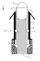
- Fig. 1 shows a side view of a first embodiment of the invention in the attached state that includes anchor 101 and a detachable electrode 102, which may be an electrode lead or a leadless medical implant.
- the electrode lead is shown as a coiled wire, while the leadless device is not shown for brevity, but rather excludes the coiled wire for example. All examples given with respect to an electrode lead may be applied equally to a leadless medical implant, such as a leadless pacemaker, drug reservoir, drug pump or any other type of leadless medical implant.
- a leadless medical implant such as a leadless pacemaker, drug reservoir, drug pump or any other type of leadless medical implant.
- the electrode lead embodiment includes an electrode, such as tip electrode 110, insulating electrode body 130 and at least one electrically conductive wire 111 internally situated within the electrode lead and having a first detachable element 121.
- Leadless devices do not require wire 111 and communicate with wireless electromagnetic waves generally.
- Anchor 101 generally includes at least one projection 150 configured to physically attach the anchor to tissue, for example heart tissue, and a second detachable element 120.
- Embodiments of the invention are configured to enable the first detachable element to detachably engage the second detachable element to enable the anchor to remain implanted and enable the electrode to be explanted, when the electrode is removed or replaced for example.
- the electrode lead generally includes at least one conductive outer surface area and insulative portions therebetween. Any type of material may be utilized for the conductive and insulative areas that are generally biocompatible, as one skilled in the art will appreciate.
- the anchor may be constructed from any material, of any hardness or flexibility depending on the intended application.
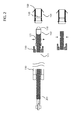
- Fig. 2 shows a side view of a first embodiment of the lead based apparatus in the detached state.
- the first detachable element in the electrode lead may include at least one radially outward oriented projection 121 that is for example radially retracted, when electrical conductor 111 is elongated through a rearward force imposed at the proximal end 201 of electrical conductor 111.
- the inner pitch of the electrical conductor increases, which reduces the outer diameter of the electrical conductor, which reduces the force against the at least one radially outward oriented indentation 120, and for example disengages projection 121 from indentation 120.
- the sides of the leadless device may also be non-rigid, and which elongate, and thus narrow when a longitudinal force is applied.
- the indentation is inwardly oriented into the electrical conductor and the projection is inward from the anchor towards the centerline of the apparatus that is defined as the innermost portion of the cylindrical electrode line parallel to the direction of the electrode body for example.
- the first detachable element in the electrode lead includes at least one radially inward oriented indentation, e.g., element 121 is part of the anchor while the indentation 120 is part of the electrode lead.
- Leadless devices may also be configured with a corresponding indentation.
- Embodiments of the first detachable element associated with the electrode may include at least one bearing, wherein the second detachable element in the anchor includes an indentation configured to engage the at least one bearing.
- the first detachable element in the electrode lead includes an indentation, wherein the second detachable element in the anchor includes at least one bearing configured to engage the indentation.
- the embodiments that employ bearings may couple with a ring type indentation, in which case the coupling is an axial rotational coupling or multiple indentations for example that correspond to more or less of the bearings to facilitate fixed rotational relationship between the electrode lead and anchor.
- Embodiments may also employ a ring projection to enable a rotational type coupling between the electrode lead and anchor.
- the first detachable element in the electrode lead includes a ring for example that projects outwardly and wherein the second detachable element in the anchor includes an indentation wherein the indentation is configured to engage the ring.
- the first detachable element in the electrode lead includes at least one radially inward oriented indentation
- the second detachable element in the anchor includes a ring configured to engage the at least one radially inward oriented indentation.
- the electrode lead is flexible, and requires force to reduce the diameter of the electrode lead.
- the first detachable element and the second detachable element are coupled together based on radially outward force provided by the electrode lead.
- the pitch of the electrical conductor is increased, which decreases the diameter of the electrode lead, reduces the force between the electrode lead and anchor to the point at which the electrode lead may be removed from the anchor without explanting the anchor.
- the detachable elements are acceptable according to embodiments of, and in keeping with the spirit of the invention.
- a wire with a hook or any other device may be utilized to exert a longitudinal force to the leadless implant as desired in any manner that is capable of supplying a longitudinal force to the implant.
- the first detachable element and the second detachable element may be coupled together at least based on radially inward force provided by the anchor.
- the anchor may squeeze or in any other manner impart force on the detachable element in the electrode lead.
- the first detachable element and the second detachable element are coupled together based on radially outward force provided by the electrode lead and radially inward force provided by the anchor.
- force applied from one detachable element is opposed by the corresponding detachable element in the other object, otherwise motion occurs.
- force as described herein it is the primary supplier of force that is described, not the opposing force element.
- the first detachable element includes a temperature dependent hardness.
- Example temperature dependent hardness characteristics include shape memory, superelasticity and any other physical characteristic that may be changed over a biocompatible temperature range.
- An example material that exhibits this type of physical property includes nickel titanium, otherwise known as nitinol. Any other material that may change shape based on temperature may be utilized in keeping with the spirit of the invention. For example, by cooling the detachable elements, they may deform, become superelastic, more flexible or otherwise more able to detach.
- the temperature change may be asserted in the form of cooling the anchor or distal end of the electrode lead, either from within the lead by injecting cool or cold biocompatible liquids having a biocompatible temperature, or by externally cooling the area around the anchor or electrode lead.
- heated liquids or heating elements may be utilized to lower the disengagement force between the detachable elements.
- Any temperature dependent change that lowers the force required to disengage the detachable elements and any material that includes biocompatible temperature dependent hardness may be utilized for embodiments of the detachable elements in keeping with the spirit of the invention.
- the temperature dependent material may also be utilized for the second detachable element as well, or for both the first and second detachable elements. The same mechanisms described with respect to electrode lead embodiments may be applied to leadless implantable devices as well.
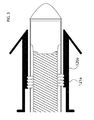
- Fig. 3 shows a side view of a second embodiment of the invention in the attached state.
- the first detachable element in the electrode lead may include a first threaded element 121a and the second detachable element 120a in the anchor may include a second threaded element configured to rotationally engage the first threaded element.
- This embodiment allows for rotational forces at the end of the electrode lead to disengage the electrode lead from the anchor.
- Leadless devices may also include hex nuts or facets in any number or spanner type coupling elements or slots or any other geometric shape that allows for rotational forces to be applied to couple the leadless device to the anchor as one skilled in the art will recognize.
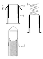
- Fig. 4 shows a side view of a second embodiment of the invention in the detached state.
- the attachment mechanism 150 is shown as rearward oriented tines, the attachment mechanism may also include a helix 160, for example of the opposing rotational orientation with respect to the threads 120a and 121a, so that rotation in one clockwise direction to detach the detachable elements from one another does not disengage the helix from the tissue.
Landscapes
- Health & Medical Sciences (AREA)
- Heart & Thoracic Surgery (AREA)
- Animal Behavior & Ethology (AREA)
- Nuclear Medicine, Radiotherapy & Molecular Imaging (AREA)
- Radiology & Medical Imaging (AREA)
- Life Sciences & Earth Sciences (AREA)
- Biomedical Technology (AREA)
- General Health & Medical Sciences (AREA)
- Public Health (AREA)
- Veterinary Medicine (AREA)
- Engineering & Computer Science (AREA)
- Cardiology (AREA)
- Vascular Medicine (AREA)
- Electrotherapy Devices (AREA)
Abstract
Description
- At least one embodiment of the invention generally relates to implantable medical devices that may later be detached and which may include electrodes, including electrode leads and leadless medical implants having at least one electrode and more particularly, but not by way of limitation, embodiments of the invention relate to a detachable electrode and anchor that may be detachably released from one another to explant the electrode and associated lead or leadless implant.
- Electrodes in the form of electrode leads or leadless medical implants are commonly implanted in patients in need of cardiac monitoring and if necessary, electrical stimulation. Electrical energy is sensed over the electrodes and analyzed, generally with an associated implantable medical device, or external device. Therapeutic energy is provided to the electrodes implanted in a heart for example to ensure that the heart provides life-sustaining contractions that pump blood through the patient's body. Generally, electrodes are physically attached to the heart in a manner that is intended to be relatively permanent, so as to ensure long term robust electrical contact with the specific heart tissue that the electrode is attached to. Typical electrodes provide attachment mechanisms such as screws or tines that project in one way or another into the tissue of the heart. Leadless devices have many advantages includes avoiding problems associated with lead failure.
- When an electrode lead is no longer needed, or becomes inoperable, or otherwise is to be replaced, the electrode lead may be left in place, or removed. Leaving unused electrode leads in place is suboptimal in that the unused leads may interfere with the internal workings of the veins or portion of the heart in which they remain. Alternatively, removing the electrode lead may damage the tissue where the electrode lead is attached. If the electrode lead is to be removed, one such method of removing an unwanted electrode lead requires use of an additional sheath that is placed over the electrode lead that abuts against the heart tissue where the electrode lead is attached. The electrode lead is then physically removed from the scar tissue that has grown around the attachment portion or anchor of the electrode lead, for example the tines. Optionally, a laser or mechanical drill may be utilized to cut or otherwise remove scar tissue surrounding the tines before the anchor of the electrode lead is removed. The main problem with this technique is that the extraction site is subject to internal bleeding. Leadless medical implants on the other hand are generally never removed and remain attached to tissue even after a battery within the device is drained, which is also suboptimal.
- At least one embodiment of the invention provides a detachable electrode and anchor that enables explantation of the electrode lead or leadless implantable device while leaving the anchor in place. In one or more embodiments, the electrode may include a tip electrode, an insulating electrode body and at least one electrically conductive wire internally situated within an electrode lead embodiment, and having a first detachable element. The anchor generally includes at least one projection configured to physically attach the anchor to tissue, for example heart tissue, and a second detachable element. Embodiments of the invention are configured to enable the first detachable element to detachably engage the second detachable element to enable the anchor to remain implanted and enable the electrode to be explanted, when the electrode is removed or replaced for example. The electrode generally includes at least one conductive outer surface area and insulative portions therebetween. Any type of material may be utilized for the conductive and insulative areas that are generally biocompatible, as one skilled in the art will appreciate. The anchor may be constructed from any material, of any hardness or flexibility depending on the intended application. Embodiments do not require removal of existing scar tissue before explantation, which minimize chances of internal bleeding at the extraction site. Embodiments also minimize impact on the vein in which the electrode travels by eliminating use of a necessarily larger diameter sheath that is utilized around the electrode to remove the electrode and attached anchor for example.
- The first detachable element associated with the electrode may include at least one radially outward oriented projection that is for example radially retracted, when the electrical conductor is elongated through a rearward force imposed at the proximal end of the electrical conductor. By stretching or otherwise elongating the electrical conductor, the inner pitch of the electrical conductor increases, which reduces the outer diameter of the electrical conductor, which reduces the force against the at least one radially outward oriented indentation, and for example disengages at least one projection from at least one indentation. Alternatively, in one or more embodiments the indentation is inwardly oriented into the electrical conductor and the projection is inward from the anchor towards the centerline of the apparatus that is defined as the innermost portion of the cylindrical electrode line parallel to the direction of the electrode body for example. In this embodiment, the first detachable element associated with the electrode includes at least one radially inward oriented indentation.
- Embodiments of the first detachable element associated with the electrode may include at least one bearing, wherein the second detachable element in the anchor includes an indentation configured to engage the at least one bearing. Alternatively, the first detachable element associated with the electrode includes an indentation, wherein the second detachable element in the anchor includes at least one bearing configured to engage the indentation.
- The embodiments that employ bearings may couple with a ring type indentation, in which case the coupling is an axial rotational coupling or multiple indentations for example that correspond to more or less of the bearings to facilitate fixed rotational relationship between the electrode and anchor. Embodiments may also employ a ring projection to enable a rotational type coupling between the electrode and anchor. For example, in one or more embodiments, the first detachable element includes a ring for example that projects outwardly and wherein the second detachable element in the anchor includes an indentation wherein the indentation is configured to engage the ring. Alternatively, the first detachable element includes at least one radially inward oriented indentation, wherein the second detachable element in the anchor includes a ring configured to engage the at least one radially inward oriented indentation.
- In one or more embodiments, the first detachable element includes a temperature dependent hardness. Example temperature dependent hardness characteristics include shape memory, superelasticity and any other physical characteristic that may be changed over a biocompatible temperature range. An example material that exhibits this type of physical property includes nickel titanium, otherwise known as nitinol. Any other material that may change shape based on temperature may be utilized in keeping with the spirit of the invention. For example, by cooling the detachable elements, they may deform, become superelastic, more flexible or otherwise more able to detach. The temperature change may be asserted in the form of cooling the anchor or distal end of the electrode, either from within the lead by injecting cool or cold biocompatible liquids having a biocompatible temperature, or by externally cooling the area around the anchor or electrode. For types of materials that change physical properties when heated, heated liquids or heating elements may be utilized to lower the disengagement force between the detachable elements. Any temperature dependent change that lowers the force required to disengage the detachable elements and any material that includes biocompatible temperature dependent hardness may be utilized for embodiments of the detachable elements in keeping with the spirit of the invention. The temperature dependent material may also be utilized for the second detachable element as well, or for both the first and second detachable elements.
- The first detachable element may include a first threaded element and the second detachable element in the anchor may include a second threaded element configured to rotationally engage the first threaded element. This embodiment allows for rotational forces near the end of the electrode to disengage the electrode from the anchor. The attachment mechanism on the anchor may also include or otherwise employ a helix, for example of the opposing rotational orientation with respect to the threads, so that rotation in one clockwise direction to detach the detachable elements from one another does not disengage the helix from the tissue, but rather provides a force associated with insertion of the helix.
- The above and other aspects, features and advantages of at least one embodiment of the invention will be more apparent from the following more particular description thereof, presented in conjunction with the following drawings wherein:
- Fig. 1
- shows a side view of a first embodiment of the invention in the attached state.
- Fig. 2
- shows a side view of a first embodiment of the invention in the detached state.
- Fig. 3
- shows a side view of a second embodiment of the invention in the attached state.
- Fig. 4
- shows a side view of a second embodiment of the invention in the detached state.
- The following description is of the best mode presently contemplated for carrying out at least one embodiment of the invention. This description is not to be taken in a limiting sense, but is made merely for the purpose of describing the general principles of the invention. The scope of the invention should be determined with reference to the claims.
-
Fig. 1 shows a side view of a first embodiment of the invention in the attached state that includesanchor 101 and adetachable electrode 102, which may be an electrode lead or a leadless medical implant. The electrode lead is shown as a coiled wire, while the leadless device is not shown for brevity, but rather excludes the coiled wire for example. All examples given with respect to an electrode lead may be applied equally to a leadless medical implant, such as a leadless pacemaker, drug reservoir, drug pump or any other type of leadless medical implant. Although many examples are given with respect to electrode leads, this does not limit the use of the apparatus described herein to electrode leads, but is described with respect to electrode leads for brevity. - In one or more embodiments, the electrode lead embodiment includes an electrode, such as
tip electrode 110,insulating electrode body 130 and at least one electricallyconductive wire 111 internally situated within the electrode lead and having a firstdetachable element 121. Leadless devices do not requirewire 111 and communicate with wireless electromagnetic waves generally. -
Anchor 101 generally includes at least oneprojection 150 configured to physically attach the anchor to tissue, for example heart tissue, and a seconddetachable element 120. Embodiments of the invention are configured to enable the first detachable element to detachably engage the second detachable element to enable the anchor to remain implanted and enable the electrode to be explanted, when the electrode is removed or replaced for example. The electrode lead generally includes at least one conductive outer surface area and insulative portions therebetween. Any type of material may be utilized for the conductive and insulative areas that are generally biocompatible, as one skilled in the art will appreciate. The anchor may be constructed from any material, of any hardness or flexibility depending on the intended application. -
Fig. 2 shows a side view of a first embodiment of the lead based apparatus in the detached state. As shown, the first detachable element in the electrode lead may include at least one radially outward orientedprojection 121 that is for example radially retracted, whenelectrical conductor 111 is elongated through a rearward force imposed at the proximal end 201 ofelectrical conductor 111. By stretching or otherwise elongating theelectrical conductor 111, the inner pitch of the electrical conductor increases, which reduces the outer diameter of the electrical conductor, which reduces the force against the at least one radially outward orientedindentation 120, and for example disengagesprojection 121 fromindentation 120. In the case of leadless implantable devices, the sides of the leadless device may also be non-rigid, and which elongate, and thus narrow when a longitudinal force is applied. - Alternatively, as shown in the bottom portion of the figure, in one or more embodiments the indentation is inwardly oriented into the electrical conductor and the projection is inward from the anchor towards the centerline of the apparatus that is defined as the innermost portion of the cylindrical electrode line parallel to the direction of the electrode body for example. In this embodiment, the first detachable element in the electrode lead includes at least one radially inward oriented indentation, e.g.,
element 121 is part of the anchor while theindentation 120 is part of the electrode lead. Leadless devices may also be configured with a corresponding indentation. - Embodiments of the first detachable element associated with the electrode may include at least one bearing, wherein the second detachable element in the anchor includes an indentation configured to engage the at least one bearing. Alternatively, the first detachable element in the electrode lead includes an indentation, wherein the second detachable element in the anchor includes at least one bearing configured to engage the indentation.
- The embodiments that employ bearings may couple with a ring type indentation, in which case the coupling is an axial rotational coupling or multiple indentations for example that correspond to more or less of the bearings to facilitate fixed rotational relationship between the electrode lead and anchor.
- Embodiments may also employ a ring projection to enable a rotational type coupling between the electrode lead and anchor. For example, in one or more embodiments, the first detachable element in the electrode lead includes a ring for example that projects outwardly and wherein the second detachable element in the anchor includes an indentation wherein the indentation is configured to engage the ring. Alternatively, the first detachable element in the electrode lead includes at least one radially inward oriented indentation, wherein the second detachable element in the anchor includes a ring configured to engage the at least one radially inward oriented indentation.
- In one or more embodiments, the electrode lead is flexible, and requires force to reduce the diameter of the electrode lead. In this embodiment, the first detachable element and the second detachable element are coupled together based on radially outward force provided by the electrode lead. As described above, when the end of the electrode lead is extended away from the anchor, the pitch of the electrical conductor is increased, which decreases the diameter of the electrode lead, reduces the force between the electrode lead and anchor to the point at which the electrode lead may be removed from the anchor without explanting the anchor. Hence as long as the force required to detach the electrode lead from the anchor is less than the force required to explant the anchor from the tissue, then the detachable elements are acceptable according to embodiments of, and in keeping with the spirit of the invention. The same technique may be utilized with flexible embodiments of leadless devices, or leadless devices that are rigid and include a compressible ring or bearings as one skilled in the art will recognize. A wire with a hook or any other device may be utilized to exert a longitudinal force to the leadless implant as desired in any manner that is capable of supplying a longitudinal force to the implant. Alternatively, the first detachable element and the second detachable element may be coupled together at least based on radially inward force provided by the anchor. For example, in embodiments that employ a flexible anchor, the anchor may squeeze or in any other manner impart force on the detachable element in the electrode lead. In one or more embodiments, the first detachable element and the second detachable element are coupled together based on radially outward force provided by the electrode lead and radially inward force provided by the anchor. One skilled in the art will appreciate that in a static orientation, force applied from one detachable element is opposed by the corresponding detachable element in the other object, otherwise motion occurs. By force as described herein, it is the primary supplier of force that is described, not the opposing force element.
- In one or more embodiments, the first detachable element includes a temperature dependent hardness. Example temperature dependent hardness characteristics include shape memory, superelasticity and any other physical characteristic that may be changed over a biocompatible temperature range. An example material that exhibits this type of physical property includes nickel titanium, otherwise known as nitinol. Any other material that may change shape based on temperature may be utilized in keeping with the spirit of the invention. For example, by cooling the detachable elements, they may deform, become superelastic, more flexible or otherwise more able to detach. The temperature change may be asserted in the form of cooling the anchor or distal end of the electrode lead, either from within the lead by injecting cool or cold biocompatible liquids having a biocompatible temperature, or by externally cooling the area around the anchor or electrode lead. For types of materials that change physical properties when heated, heated liquids or heating elements may be utilized to lower the disengagement force between the detachable elements. Any temperature dependent change that lowers the force required to disengage the detachable elements and any material that includes biocompatible temperature dependent hardness may be utilized for embodiments of the detachable elements in keeping with the spirit of the invention. The temperature dependent material may also be utilized for the second detachable element as well, or for both the first and second detachable elements. The same mechanisms described with respect to electrode lead embodiments may be applied to leadless implantable devices as well.
-
Fig. 3 shows a side view of a second embodiment of the invention in the attached state. In this embodiment, the first detachable element in the electrode lead may include a first threadedelement 121a and the seconddetachable element 120a in the anchor may include a second threaded element configured to rotationally engage the first threaded element. This embodiment allows for rotational forces at the end of the electrode lead to disengage the electrode lead from the anchor. Leadless devices may also include hex nuts or facets in any number or spanner type coupling elements or slots or any other geometric shape that allows for rotational forces to be applied to couple the leadless device to the anchor as one skilled in the art will recognize. -
Fig. 4 shows a side view of a second embodiment of the invention in the detached state. Although theattachment mechanism 150 is shown as rearward oriented tines, the attachment mechanism may also include ahelix 160, for example of the opposing rotational orientation with respect to thethreads
Claims (15)
- A detachable electrode and anchor (100) comprising
an electrode (101) comprising at least one electrically conductive element (111) wherein said electrode is coupled with a first detachable element (121, 121a);
an anchor (102) comprising at least one projection (150) configured to physically attach said anchor to tissue and further comprising a second detachable element (120, 120a); and,
said first detachable element configured to detachably engage said second detachable element to enable said anchor to remain implanted and enable said electrode to be explanted. - The detachable electrode and anchor (100) according to claim 1, wherein
said first detachable element (121) coupled with said electrode (101) comprising at least one radially oriented projection; and
said second detachable element (120) in said anchor (102) comprising at least one radially oriented indentation configured to engage said at least one radially outward oriented projection. - The detachable electrode and anchor (100) according to claim 1, wherein
said first detachable element (121) coupled with said electrode (101) comprising a ring; and
said second detachable element (120) in said anchor (102) comprising an indentation wherein said indentation is configured to engage said ring. - The detachable electrode and anchor (100) according to claim 1, wherein
said first detachable element (121) coupled with said electrode (101) comprising at least one bearing; and,
said second detachable element (120) in said anchor (102) comprising an indentation configured to engage said at least one bearing. - The detachable electrode and anchor (100) according to claim 1, wherein
said first detachable element (121) coupled with said electrode (101) comprising at least one radially inward oriented indentation; and,
said second detachable element (120) in said anchor (102) comprising a ring configured to engage said at least one radially inward oriented indentation. - The detachable electrode and anchor (100) according to claim 1 to 5, wherein said first detachable element (121) and said second detachable element (120) coupled together based on radially force provided by said anchor (102).
- The detachable electrode and anchor (100) according to claim 1 to 6, wherein said first detachable element (121) comprises a temperature dependent hardness.
- The detachable electrode and anchor (100) according to claim 1 to 6, wherein said second detachable element (120) comprises a temperature dependent hardness.
- The detachable electrode and anchor (100) according to claim 1 to 8, wherein said first detachable element (121) and said second detachable element (120) comprise a temperature dependent hardness.
- The detachable electrode and anchor (100) according to claim 1, wherein
said first detachable element (121a) coupled with said electrode (101) comprising a first threaded element; and
said second detachable element (120a) in said anchor (102) comprising a second threaded element configured to rotationally engage said first threaded element. - The detachable electrode and anchor (100) according to claim 10, wherein the said first detachable element coupled with said electrode comprising at least one projection (150) of said anchor (102) comprises a helix of a rotational orientation that is opposite of said first and said second threaded elements (120, 120a) so that a disengagement rotational force applied to said first and said second threaded elements applies a tightening force to said helix.
- The detachable electrode and anchor (100) according to claim 1 to 11, wherein said electrode (101) is coupled with an electrode lead comprising an electrical conductor (111).
- The detachable electrode and anchor (100) according to claim 1 to 11, wherein said electrode (101) is coupled with a leadless medical device.
- The detachable electrode and anchor (100) according to claim 1 to 11, wherein said electrode (101) is a component of an electrode lead.
- The detachable electrode and anchor (100) according to claim 1 to 11, wherein said electrode (101) is a component of a leadless implantable device.
Applications Claiming Priority (1)
| Application Number | Priority Date | Filing Date | Title |
|---|---|---|---|
| US201261730064P | 2012-11-27 | 2012-11-27 |
Publications (1)
| Publication Number | Publication Date |
|---|---|
| EP2735336A1 true EP2735336A1 (en) | 2014-05-28 |
Family
ID=49515214
Family Applications (1)
| Application Number | Title | Priority Date | Filing Date |
|---|---|---|---|
| EP13190462.5A Ceased EP2735336A1 (en) | 2012-11-27 | 2013-10-28 | Detachable electrode and anchor |
Country Status (2)
| Country | Link |
|---|---|
| US (1) | US9308365B2 (en) |
| EP (1) | EP2735336A1 (en) |
Cited By (1)
| Publication number | Priority date | Publication date | Assignee | Title |
|---|---|---|---|---|
| EP4035727A4 (en) * | 2019-09-26 | 2022-10-26 | MicroPort Soaring CRM (Shanghai) Co., Ltd. | LEADLESS CARDIAC PACEMAKER, HEAD END COMPONENT, TAIL END COMPONENT AND PLACEMENT DEVICE |
Families Citing this family (105)
| Publication number | Priority date | Publication date | Assignee | Title |
|---|---|---|---|---|
| US20150196769A1 (en) | 2014-01-10 | 2015-07-16 | Cardiac Pacemakers, Inc. | Methods and systems for improved communication between medical devices |
| EP3092034B1 (en) | 2014-01-10 | 2019-10-30 | Cardiac Pacemakers, Inc. | Systems for detecting cardiac arrhythmias |
| US9526909B2 (en) | 2014-08-28 | 2016-12-27 | Cardiac Pacemakers, Inc. | Medical device with triggered blanking period |
| WO2016126613A1 (en) | 2015-02-06 | 2016-08-11 | Cardiac Pacemakers, Inc. | Systems and methods for treating cardiac arrhythmias |
| WO2016126968A1 (en) | 2015-02-06 | 2016-08-11 | Cardiac Pacemakers, Inc. | Systems and methods for safe delivery of electrical stimulation therapy |
| WO2016130477A2 (en) | 2015-02-09 | 2016-08-18 | Cardiac Pacemakers, Inc. | Implantable medical device with radiopaque id tag |
| CN107530002B (en) | 2015-03-04 | 2021-04-30 | 心脏起搏器股份公司 | System and method for treating cardiac arrhythmias |
| US10050700B2 (en) | 2015-03-18 | 2018-08-14 | Cardiac Pacemakers, Inc. | Communications in a medical device system with temporal optimization |
| EP3270768B1 (en) | 2015-03-18 | 2023-12-13 | Cardiac Pacemakers, Inc. | Communications in a medical device system with link quality assessment |
| EP3337558B1 (en) | 2015-08-20 | 2025-05-28 | Cardiac Pacemakers, Inc. | Methods for communication between medical devices |
| US10357159B2 (en) | 2015-08-20 | 2019-07-23 | Cardiac Pacemakers, Inc | Systems and methods for communication between medical devices |
| US9956414B2 (en) | 2015-08-27 | 2018-05-01 | Cardiac Pacemakers, Inc. | Temporal configuration of a motion sensor in an implantable medical device |
| US9968787B2 (en) | 2015-08-27 | 2018-05-15 | Cardiac Pacemakers, Inc. | Spatial configuration of a motion sensor in an implantable medical device |
| CN108136189B (en) | 2015-08-28 | 2021-10-15 | 心脏起搏器股份公司 | System for Behavioral Response Signal Detection and Therapeutic Delivery |
| US10226631B2 (en) | 2015-08-28 | 2019-03-12 | Cardiac Pacemakers, Inc. | Systems and methods for infarct detection |
| WO2017040115A1 (en) | 2015-08-28 | 2017-03-09 | Cardiac Pacemakers, Inc. | System for detecting tamponade |
| US10092760B2 (en) | 2015-09-11 | 2018-10-09 | Cardiac Pacemakers, Inc. | Arrhythmia detection and confirmation |
| CN108136185B (en) | 2015-10-08 | 2021-08-31 | 心脏起搏器股份公司 | Apparatus and method for adjusting pacing rate in an implantable medical device |
| JP6608063B2 (en) | 2015-12-17 | 2019-11-20 | カーディアック ペースメイカーズ, インコーポレイテッド | Implantable medical device |
| US10905886B2 (en) | 2015-12-28 | 2021-02-02 | Cardiac Pacemakers, Inc. | Implantable medical device for deployment across the atrioventricular septum |
| US10583303B2 (en) | 2016-01-19 | 2020-03-10 | Cardiac Pacemakers, Inc. | Devices and methods for wirelessly recharging a rechargeable battery of an implantable medical device |
| WO2017136548A1 (en) | 2016-02-04 | 2017-08-10 | Cardiac Pacemakers, Inc. | Delivery system with force sensor for leadless cardiac device |
| EP3436137B1 (en) | 2016-03-31 | 2021-12-15 | Cardiac Pacemakers, Inc. | Extraction devices configued to extract chronically implanted medical devices |
| CN108883286B (en) | 2016-03-31 | 2021-12-07 | 心脏起搏器股份公司 | Implantable medical device with rechargeable battery |
| JP6692920B2 (en) | 2016-03-31 | 2020-05-13 | カーディアック ペースメイカーズ, インコーポレイテッド | Implantable medical device configured for deployment within a patient's heart chamber and implantable medical device configured for deployment within a patient's body |
| US10328272B2 (en) | 2016-05-10 | 2019-06-25 | Cardiac Pacemakers, Inc. | Retrievability for implantable medical devices |
| US10668294B2 (en) | 2016-05-10 | 2020-06-02 | Cardiac Pacemakers, Inc. | Leadless cardiac pacemaker configured for over the wire delivery |
| EP3474945B1 (en) | 2016-06-27 | 2022-12-28 | Cardiac Pacemakers, Inc. | Cardiac therapy system using subcutaneously sensed p-waves for resynchronization pacing management |
| WO2018008019A2 (en) * | 2016-07-03 | 2018-01-11 | Tel Hashomer Medical Research, Infrastructure And Services Ltd. | Apparatus for delivering electrical signals to the heart |
| US11207527B2 (en) | 2016-07-06 | 2021-12-28 | Cardiac Pacemakers, Inc. | Method and system for determining an atrial contraction timing fiducial in a leadless cardiac pacemaker system |
| WO2018009392A1 (en) | 2016-07-07 | 2018-01-11 | Cardiac Pacemakers, Inc. | Leadless pacemaker using pressure measurements for pacing capture verification |
| EP3487579B1 (en) | 2016-07-20 | 2020-11-25 | Cardiac Pacemakers, Inc. | System for utilizing an atrial contraction timing fiducial in a leadless cardiac pacemaker system |
| US10391319B2 (en) | 2016-08-19 | 2019-08-27 | Cardiac Pacemakers, Inc. | Trans septal implantable medical device |
| EP3503970B1 (en) | 2016-08-24 | 2023-01-04 | Cardiac Pacemakers, Inc. | Cardiac resynchronization using fusion promotion for timing management |
| EP3503799B1 (en) | 2016-08-24 | 2021-06-30 | Cardiac Pacemakers, Inc. | Integrated multi-device cardiac resynchronization therapy using p-wave to pace timing |
| WO2018057318A1 (en) | 2016-09-21 | 2018-03-29 | Cardiac Pacemakers, Inc. | Leadless stimulation device with a housing that houses internal components of the leadless stimulation device and functions as the battery case and a terminal of an internal battery |
| US10758737B2 (en) | 2016-09-21 | 2020-09-01 | Cardiac Pacemakers, Inc. | Using sensor data from an intracardially implanted medical device to influence operation of an extracardially implantable cardioverter |
| US10994145B2 (en) | 2016-09-21 | 2021-05-04 | Cardiac Pacemakers, Inc. | Implantable cardiac monitor |
| WO2018081237A1 (en) | 2016-10-27 | 2018-05-03 | Cardiac Pacemakers, Inc. | Use of a separate device in managing the pace pulse energy of a cardiac pacemaker |
| US10413733B2 (en) | 2016-10-27 | 2019-09-17 | Cardiac Pacemakers, Inc. | Implantable medical device with gyroscope |
| WO2018081275A1 (en) | 2016-10-27 | 2018-05-03 | Cardiac Pacemakers, Inc. | Multi-device cardiac resynchronization therapy with timing enhancements |
| WO2018081133A1 (en) | 2016-10-27 | 2018-05-03 | Cardiac Pacemakers, Inc. | Implantable medical device having a sense channel with performance adjustment |
| US10765871B2 (en) | 2016-10-27 | 2020-09-08 | Cardiac Pacemakers, Inc. | Implantable medical device with pressure sensor |
| CN109922860B (en) | 2016-10-27 | 2023-07-04 | 心脏起搏器股份公司 | Implantable medical device delivery system with integrated sensors |
| CN109952128B (en) | 2016-10-31 | 2023-06-13 | 心脏起搏器股份公司 | System for activity level pacing |
| CN109890456B (en) | 2016-10-31 | 2023-06-13 | 心脏起搏器股份公司 | System for activity level pacing |
| US10583301B2 (en) | 2016-11-08 | 2020-03-10 | Cardiac Pacemakers, Inc. | Implantable medical device for atrial deployment |
| WO2018089308A1 (en) | 2016-11-09 | 2018-05-17 | Cardiac Pacemakers, Inc. | Systems, devices, and methods for setting cardiac pacing pulse parameters for a cardiac pacing device |
| CN109982746B (en) | 2016-11-21 | 2023-04-04 | 心脏起搏器股份公司 | Leadless cardiac pacemaker providing cardiac resynchronization therapy |
| CN109982738B (en) | 2016-11-21 | 2021-06-22 | 心脏起搏器股份公司 | Delivery device and wall attachment sensing |
| WO2018094344A2 (en) | 2016-11-21 | 2018-05-24 | Cardiac Pacemakers, Inc | Leadless cardiac pacemaker with multimode communication |
| US10881869B2 (en) | 2016-11-21 | 2021-01-05 | Cardiac Pacemakers, Inc. | Wireless re-charge of an implantable medical device |
| US11198013B2 (en) | 2016-11-21 | 2021-12-14 | Cardiac Pacemakers, Inc. | Catheter and leadless cardiac devices including electrical pathway barrier |
| EP3541472B1 (en) | 2016-11-21 | 2023-06-07 | Cardiac Pacemakers, Inc. | Implantable medical device with a magnetically permeable housing and an inductive coil disposed about the housing |
| US10639486B2 (en) | 2016-11-21 | 2020-05-05 | Cardiac Pacemakers, Inc. | Implantable medical device with recharge coil |
| US10485981B2 (en) | 2016-12-27 | 2019-11-26 | Cardiac Pacemakers, Inc. | Fixation methods for leadless cardiac devices |
| EP3562545B1 (en) | 2016-12-27 | 2023-11-08 | Cardiac Pacemakers, Inc. | Delivery devices and methods for leadless cardiac devices |
| US10806931B2 (en) | 2016-12-27 | 2020-10-20 | Cardiac Pacemakers, Inc. | Delivery devices and methods for leadless cardiac devices |
| AU2017387024B2 (en) | 2016-12-27 | 2020-04-09 | Cardiac Pacemakers, Inc. | Leadless delivery catheter with conductive pathway |
| US11207532B2 (en) | 2017-01-04 | 2021-12-28 | Cardiac Pacemakers, Inc. | Dynamic sensing updates using postural input in a multiple device cardiac rhythm management system |
| US10029107B1 (en) | 2017-01-26 | 2018-07-24 | Cardiac Pacemakers, Inc. | Leadless device with overmolded components |
| EP3573706B1 (en) | 2017-01-26 | 2025-08-27 | Cardiac Pacemakers, Inc. | Intra-body device communication with redundant message transmission |
| CN110198759B (en) | 2017-01-26 | 2023-08-11 | 心脏起搏器股份公司 | Leadless implantable device with removable fasteners |
| CN110225779B (en) | 2017-01-26 | 2023-04-04 | 心脏起搏器股份公司 | Delivery device for leadless cardiac devices |
| CN110418661B (en) | 2017-03-10 | 2024-01-02 | 心脏起搏器股份公司 | Fixtures for leadless cardiac devices |
| US10737092B2 (en) | 2017-03-30 | 2020-08-11 | Cardiac Pacemakers, Inc. | Delivery devices and methods for leadless cardiac devices |
| US10821288B2 (en) | 2017-04-03 | 2020-11-03 | Cardiac Pacemakers, Inc. | Cardiac pacemaker with pacing pulse energy adjustment based on sensed heart rate |
| US10905872B2 (en) | 2017-04-03 | 2021-02-02 | Cardiac Pacemakers, Inc. | Implantable medical device with a movable electrode biased toward an extended position |
| US11577085B2 (en) | 2017-08-03 | 2023-02-14 | Cardiac Pacemakers, Inc. | Delivery devices and methods for leadless cardiac devices |
| WO2019036568A1 (en) | 2017-08-18 | 2019-02-21 | Cardiac Pacemakers, Inc. | Implantable medical device with a flux concentrator and a receiving coil disposed about the flux concentrator |
| EP3668592B1 (en) | 2017-08-18 | 2021-11-17 | Cardiac Pacemakers, Inc. | Implantable medical device with pressure sensor |
| US10933247B2 (en) * | 2017-08-21 | 2021-03-02 | MRM MedTech, LLC | Lead with integrated features to facilitate extraction and associated methods of extraction |
| US11865334B2 (en) * | 2017-08-21 | 2024-01-09 | MRM MedTech, LLC | Lead with integrated feature including a low friction component to facilitate extraction and associated methods of extraction |
| EP3684465B1 (en) | 2017-09-20 | 2021-07-14 | Cardiac Pacemakers, Inc. | Implantable medical device with multiple modes of operation |
| US11185703B2 (en) | 2017-11-07 | 2021-11-30 | Cardiac Pacemakers, Inc. | Leadless cardiac pacemaker for bundle of his pacing |
| CN111432875B (en) | 2017-12-01 | 2024-04-30 | 心脏起搏器股份公司 | Method and system for detecting atrial contraction timing reference and determining cardiac intervals from a ventricular implantable leadless cardiac pacemaker |
| WO2019108837A1 (en) | 2017-12-01 | 2019-06-06 | Cardiac Pacemakers, Inc. | Methods and systems for detecting atrial contraction timing fiducials within a search window from a ventricularly implanted leadless cardiac pacemaker |
| CN111417433B (en) | 2017-12-01 | 2024-04-30 | 心脏起搏器股份公司 | Method and system for detecting atrial contraction timing reference during ventricular filling from a ventricularly implanted leadless cardiac pacemaker |
| US11813463B2 (en) | 2017-12-01 | 2023-11-14 | Cardiac Pacemakers, Inc. | Leadless cardiac pacemaker with reversionary behavior |
| EP3735293B1 (en) | 2018-01-04 | 2022-03-09 | Cardiac Pacemakers, Inc. | Dual chamber pacing without beat-to-beat communication |
| US11529523B2 (en) | 2018-01-04 | 2022-12-20 | Cardiac Pacemakers, Inc. | Handheld bridge device for providing a communication bridge between an implanted medical device and a smartphone |
| EP3768160B1 (en) | 2018-03-23 | 2023-06-07 | Medtronic, Inc. | Vfa cardiac therapy for tachycardia |
| WO2019183507A1 (en) | 2018-03-23 | 2019-09-26 | Medtronic, Inc. | Av synchronous vfa cardiac therapy |
| JP2021518192A (en) | 2018-03-23 | 2021-08-02 | メドトロニック,インコーポレイテッド | VfA cardiac resynchronization therapy |
| WO2020065582A1 (en) | 2018-09-26 | 2020-04-02 | Medtronic, Inc. | Capture in ventricle-from-atrium cardiac therapy |
| US11951313B2 (en) | 2018-11-17 | 2024-04-09 | Medtronic, Inc. | VFA delivery systems and methods |
| WO2020132446A1 (en) | 2018-12-21 | 2020-06-25 | Medtronic, Inc. | Delivery systems and methods for left ventricular pacing |
| US11679265B2 (en) | 2019-02-14 | 2023-06-20 | Medtronic, Inc. | Lead-in-lead systems and methods for cardiac therapy |
| US11697025B2 (en) | 2019-03-29 | 2023-07-11 | Medtronic, Inc. | Cardiac conduction system capture |
| CN113660977B (en) | 2019-03-29 | 2024-12-17 | 心脏起搏器股份公司 | Systems and methods for treating cardiac arrhythmias |
| CN113677390B (en) | 2019-03-29 | 2024-12-17 | 心脏起搏器股份公司 | Systems and methods for treating cardiac arrhythmias |
| US11213676B2 (en) | 2019-04-01 | 2022-01-04 | Medtronic, Inc. | Delivery systems for VfA cardiac therapy |
| US11712188B2 (en) | 2019-05-07 | 2023-08-01 | Medtronic, Inc. | Posterior left bundle branch engagement |
| US12502167B2 (en) | 2019-07-16 | 2025-12-23 | Edwards Lifesciences Corporation | Tissue remodeling systems and methods |
| US11305127B2 (en) | 2019-08-26 | 2022-04-19 | Medtronic Inc. | VfA delivery and implant region detection |
| US11510697B2 (en) | 2019-09-11 | 2022-11-29 | Cardiac Pacemakers, Inc. | Tools and systems for implanting and/or retrieving a leadless cardiac pacing device with helix fixation |
| WO2021050685A1 (en) | 2019-09-11 | 2021-03-18 | Cardiac Pacemakers, Inc. | Tools and systems for implanting and/or retrieving a leadless cardiac pacing device with helix fixation |
| US11813466B2 (en) | 2020-01-27 | 2023-11-14 | Medtronic, Inc. | Atrioventricular nodal stimulation |
| US12543992B2 (en) | 2020-03-30 | 2026-02-10 | Medtronic, Inc. | Pacing efficacy determination using a representative morphology of external cardiac signals |
| US11911168B2 (en) | 2020-04-03 | 2024-02-27 | Medtronic, Inc. | Cardiac conduction system therapy benefit determination |
| US12605103B2 (en) | 2020-05-21 | 2026-04-21 | Medtronic, Inc. | QRS detection and bracketing |
| US12465770B2 (en) | 2020-07-31 | 2025-11-11 | Medtronic, Inc. | Coronary sinus conduction system pacing and delivery |
| US11813464B2 (en) | 2020-07-31 | 2023-11-14 | Medtronic, Inc. | Cardiac conduction system evaluation |
| CN115253068B (en) * | 2022-08-08 | 2026-02-27 | 郭成军 | A detachable leadless pacemaker system with a paced cardiac conduction bundle |
| WO2025129038A1 (en) * | 2023-12-15 | 2025-06-19 | Georgia State University Research Foundation, Inc. | Electrothermally controlled coupling system for leadless implantable medical devices |
Citations (4)
| Publication number | Priority date | Publication date | Assignee | Title |
|---|---|---|---|---|
| US5383924A (en) * | 1992-06-03 | 1995-01-24 | Ela Medical | Extractable cardiac probe and its application procedure |
| US6188932B1 (en) * | 1996-11-13 | 2001-02-13 | Pacesetter Ab | Implantable electrode lead |
| US6459937B1 (en) * | 2000-04-25 | 2002-10-01 | Pacesetter, Inc. | Endocardial pacing lead with detachable tip electrode assembly |
| US20110251661A1 (en) * | 2005-08-15 | 2011-10-13 | Fifer Daniel W | Lead fixation and extraction |
Family Cites Families (3)
| Publication number | Priority date | Publication date | Assignee | Title |
|---|---|---|---|---|
| DE3020586A1 (en) * | 1980-05-30 | 1981-12-03 | Hans-Jürgen Dipl.-Ing. 5100 Aachen Bisping | IMPLANTABLE ELECTRODE PROBE |
| US5807399A (en) * | 1996-10-23 | 1998-09-15 | Medtronic, Inc. | Method for removal of chronically implanted leads and leads optimized for use therewith |
| CN103249454A (en) * | 2010-10-13 | 2013-08-14 | 内诺斯蒂姆股份有限公司 | Leadless pacemaker with anti-swivel construction |
-
2013
- 2013-09-25 US US14/037,273 patent/US9308365B2/en not_active Expired - Fee Related
- 2013-10-28 EP EP13190462.5A patent/EP2735336A1/en not_active Ceased
Patent Citations (4)
| Publication number | Priority date | Publication date | Assignee | Title |
|---|---|---|---|---|
| US5383924A (en) * | 1992-06-03 | 1995-01-24 | Ela Medical | Extractable cardiac probe and its application procedure |
| US6188932B1 (en) * | 1996-11-13 | 2001-02-13 | Pacesetter Ab | Implantable electrode lead |
| US6459937B1 (en) * | 2000-04-25 | 2002-10-01 | Pacesetter, Inc. | Endocardial pacing lead with detachable tip electrode assembly |
| US20110251661A1 (en) * | 2005-08-15 | 2011-10-13 | Fifer Daniel W | Lead fixation and extraction |
Cited By (1)
| Publication number | Priority date | Publication date | Assignee | Title |
|---|---|---|---|---|
| EP4035727A4 (en) * | 2019-09-26 | 2022-10-26 | MicroPort Soaring CRM (Shanghai) Co., Ltd. | LEADLESS CARDIAC PACEMAKER, HEAD END COMPONENT, TAIL END COMPONENT AND PLACEMENT DEVICE |
Also Published As
| Publication number | Publication date |
|---|---|
| US9308365B2 (en) | 2016-04-12 |
| US20140148675A1 (en) | 2014-05-29 |
Similar Documents
| Publication | Publication Date | Title |
|---|---|---|
| US9308365B2 (en) | Detachable electrode and anchor | |
| US10226617B2 (en) | Apparatus with unencapsulated reinforcement | |
| US10625085B2 (en) | Leadless cardiac pacemaker with delivery and/or retrieval features | |
| CN109498995B (en) | Attachment device for implantable cardiac device | |
| US9238145B2 (en) | Leadless implantable device delivery apparatus | |
| US9393427B2 (en) | Leadless cardiac pacemaker with delivery and/or retrieval features | |
| US9242102B2 (en) | Leadless pacemaker with radial fixation mechanism | |
| US9265934B2 (en) | Percutaneously implantable paddle-type lead and methods and devices for deployment | |
| CN109789304B (en) | Electrode assembly for monitoring and/or stimulating activity in a subject | |
| US20170151429A1 (en) | Implantable stimulation capsule | |
| US20120116489A1 (en) | Leadless Cardiac Pacemaker with Anti-Unscrewing Feature | |
| CN108883269A (en) | It is configured to take out the withdrawing device for the medical device being chronically implanted into | |
| CN105744987A (en) | Leadless cardiac pacemaker and retrieval device | |
| US9192317B2 (en) | Implantable active fixation lead with biodegradable helical tip | |
| WO2011119556A1 (en) | Intravascular medical device | |
| CN108079437A (en) | Pacemaker and its fixing means and transport system | |
| CN105636642A (en) | Leadless cardiac pacemaker with delivery and/or retrieval features | |
| EP2134411B1 (en) | Mri thermal switch for implantable medical devices | |
| CN119546368A (en) | Medical device fixation with anti-rotation feature | |
| US20250135212A1 (en) | Intra-cardiac device and fixing method therefor | |
| EP4052755A1 (en) | Intracardiac device and fixing method therefor | |
| WO2022152585A1 (en) | Implantable medical device | |
| CN115702019A (en) | Implantable medical lead | |
| CN120731108A (en) | Distal end fixation portion for an implantable medical device |
Legal Events
| Date | Code | Title | Description |
|---|---|---|---|
| PUAI | Public reference made under article 153(3) epc to a published international application that has entered the european phase |
Free format text: ORIGINAL CODE: 0009012 |
|
| 17P | Request for examination filed |
Effective date: 20131028 |
|
| AK | Designated contracting states |
Kind code of ref document: A1 Designated state(s): AL AT BE BG CH CY CZ DE DK EE ES FI FR GB GR HR HU IE IS IT LI LT LU LV MC MK MT NL NO PL PT RO RS SE SI SK SM TR |
|
| AX | Request for extension of the european patent |
Extension state: BA ME |
|
| R17P | Request for examination filed (corrected) |
Effective date: 20141125 |
|
| RBV | Designated contracting states (corrected) |
Designated state(s): AL AT BE BG CH CY CZ DE DK EE ES FI FR GB GR HR HU IE IS IT LI LT LU LV MC MK MT NL NO PL PT RO RS SE SI SK SM TR |
|
| 17Q | First examination report despatched |
Effective date: 20171019 |
|
| STAA | Information on the status of an ep patent application or granted ep patent |
Free format text: STATUS: THE APPLICATION HAS BEEN REFUSED |
|
| 18R | Application refused |
Effective date: 20201204 |