EP2735260A1 - Endoscope - Google Patents
Endoscope Download PDFInfo
- Publication number
- EP2735260A1 EP2735260A1 EP13818970.9A EP13818970A EP2735260A1 EP 2735260 A1 EP2735260 A1 EP 2735260A1 EP 13818970 A EP13818970 A EP 13818970A EP 2735260 A1 EP2735260 A1 EP 2735260A1
- Authority
- EP
- European Patent Office
- Prior art keywords
- air
- window
- observation window
- water feeding
- angle
- Prior art date
- Legal status (The legal status is an assumption and is not a legal conclusion. Google has not performed a legal analysis and makes no representation as to the accuracy of the status listed.)
- Granted
Links
Images



Classifications
-
- A—HUMAN NECESSITIES
- A61—MEDICAL OR VETERINARY SCIENCE; HYGIENE
- A61B—DIAGNOSIS; SURGERY; IDENTIFICATION
- A61B1/00—Instruments for performing medical examinations of the interior of cavities or tubes of the body by visual or photographical inspection, e.g. endoscopes; Illuminating arrangements therefor
- A61B1/12—Instruments for performing medical examinations of the interior of cavities or tubes of the body by visual or photographical inspection, e.g. endoscopes; Illuminating arrangements therefor with cooling or rinsing arrangements
- A61B1/126—Instruments for performing medical examinations of the interior of cavities or tubes of the body by visual or photographical inspection, e.g. endoscopes; Illuminating arrangements therefor with cooling or rinsing arrangements provided with means for cleaning in-use
-
- A—HUMAN NECESSITIES
- A61—MEDICAL OR VETERINARY SCIENCE; HYGIENE
- A61B—DIAGNOSIS; SURGERY; IDENTIFICATION
- A61B1/00—Instruments for performing medical examinations of the interior of cavities or tubes of the body by visual or photographical inspection, e.g. endoscopes; Illuminating arrangements therefor
- A61B1/00064—Constructional details of the endoscope body
- A61B1/00071—Insertion part of the endoscope body
- A61B1/0008—Insertion part of the endoscope body characterised by distal tip features
- A61B1/00091—Nozzles
-
- A—HUMAN NECESSITIES
- A61—MEDICAL OR VETERINARY SCIENCE; HYGIENE
- A61B—DIAGNOSIS; SURGERY; IDENTIFICATION
- A61B1/00—Instruments for performing medical examinations of the interior of cavities or tubes of the body by visual or photographical inspection, e.g. endoscopes; Illuminating arrangements therefor
- A61B1/00064—Constructional details of the endoscope body
- A61B1/00071—Insertion part of the endoscope body
- A61B1/0008—Insertion part of the endoscope body characterised by distal tip features
- A61B1/00096—Optical elements
-
- G—PHYSICS
- G02—OPTICS
- G02B—OPTICAL ELEMENTS, SYSTEMS OR APPARATUS
- G02B23/00—Telescopes, e.g. binoculars; Periscopes; Instruments for viewing the inside of hollow bodies; Viewfinders; Optical aiming or sighting devices
- G02B23/24—Instruments or systems for viewing the inside of hollow bodies, e.g. fibrescopes
- G02B23/2407—Optical details
- G02B23/2423—Optical details of the distal end
-
- G—PHYSICS
- G02—OPTICS
- G02B—OPTICAL ELEMENTS, SYSTEMS OR APPARATUS
- G02B23/00—Telescopes, e.g. binoculars; Periscopes; Instruments for viewing the inside of hollow bodies; Viewfinders; Optical aiming or sighting devices
- G02B23/24—Instruments or systems for viewing the inside of hollow bodies, e.g. fibrescopes
- G02B23/2476—Non-optical details, e.g. housings, mountings, supports
-
- G—PHYSICS
- G02—OPTICS
- G02B—OPTICAL ELEMENTS, SYSTEMS OR APPARATUS
- G02B23/00—Telescopes, e.g. binoculars; Periscopes; Instruments for viewing the inside of hollow bodies; Viewfinders; Optical aiming or sighting devices
- G02B23/24—Instruments or systems for viewing the inside of hollow bodies, e.g. fibrescopes
- G02B23/26—Instruments or systems for viewing the inside of hollow bodies, e.g. fibrescopes using light guides
Definitions
- the present invention relates to a structure of a distal end face of an insertion portion in an endoscope.
- endoscopes relate to the cleanability and water draining properties of an objective lens surface that serves as an observation window that is provided at a distal end portion of an endoscope.
- Japanese Patent Application Laid-Open Publication No. 2011-120863 discloses technology for an endoscope according to which an annular convex portion is provided around an observation window, an inclined face that inclines in an outer diameter direction and a vertical face are formed in the annular convex portion, and drops of water generated as the result of water feeding from an air/water feeding nozzle are received by the vertical face thereby to prevent the drops of water from flowing onto the observation window.
- Japanese Patent Application Laid-Open Publication No. 2011-255088 discloses technology for an endoscope according to which an observation window base portion is provided around an observation window, and by forming the observation window base portion in a streamline shape with respect to a flow of cleaning fluid, the fluid is swiftly moved from a position over the observation window.
- the vertical face is formed in the annular convex portion, thereby forming a stepped portion.
- This causes a problem that such an endoscope is difficult to be applied especially to an endoscope for medical use which is configured to be introduced into a living body.
- the stepped portion causes a difficulty in cleaning with a brush before and after using the endoscope.
- observation window base portion is provided in the configuration of the endoscope disclosed in the Japanese Patent Application Laid-Open Publication No. 2011-255088 , fluid remains on the observation window base portion. Such remained fluid is likely to go back to the observation window, which problematically disturbs a field of view.
- the present invention has been achieved in view of the above-described problems, and an object of the present invention is to provide an endoscope which further improves cleanability and water draining property of an observation window composed of an objective lens.
- an endoscope including a window portion and an air/water feeding nozzle at a distal end of an insertion portion, the endoscope including: a flat portion that is provided with the window portion and the air/water feeding nozzle; the window portion that protrudes by a predetermined height from the flat portion; the air/water feeding nozzle that is provided facing the window portion from the flat portion, and that ejects a fluid toward a surface of the window portion; and an inclined portion that is formed at a circumferential edge portion of the window portion; wherein, in angles of inclination with respect to the flat portion of the inclined portion, in comparison to a first angle of elevation that is an angle in a direction along a first axis that passes through a center of the window portion in an ejection direction of the fluid that is ejected from the air/water feeding nozzle, a second angle of elevation that is an angle in a direction along a second axis that is
- the endoscope of the present invention that is configured in this manner can further improve the cleanability and water draining property of the window portion.
- drawings that are based on each embodiment are schematic ones in which a relationship between a thickness and a width of each portion, thickness ratios of the respective portions and the like are different from those of actual portions, and the drawings may include portions in which dimensional relationships and ratios are different from one another.
- Fig. 1 is an overall configuration diagram of an endoscope apparatus having the endoscope of the present invention.
- an endoscope apparatus 1 includes, as principal parts, an endoscope 2, a light source apparatus 3 that supplies an illuminating light, a video processor 4 that performs processing for an electrical signal that drives an image pickup apparatus to generate a video signal, and a monitor 5 that is a display apparatus that receives the video signal and displays an endoscopic image.
- the endoscope 2 includes an insertion portion 6 that is inserted into a body cavity, an operation portion 7, and a universal cord 8.
- a connector 9 that is detachably connected to the light source apparatus 3 is provided at a distal end of the universal cord 8 whose proximal end portion is coupled to the operation portion 7.
- An electric cable 11 having, at a distal end portion, an electrical connector 10 that is connected to the video processor 4 extends from the connector 9.
- the insertion portion 6 includes a distal end portion 12, a bending portion 13, and a flexible portion 14 that are connected in series in that order from the distal end side.
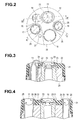
- Fig. 2 is a front view of the distal end portion as seen from the distal end face side.
- an observation window 15 of a window portion including an objective lens is arranged toward an upper side
- a suction channel 16 is arranged toward a lower side on the distal end face of the distal end portion 12.
- a large illuminating window 17 including a large illumination lens is arranged toward a left side
- a small illuminating window 18 including a small illumination lens is arranged toward a right side.
- a discharge port of an air/water feeding nozzle 19 is arranged facing toward the observation window 15 at a position that is adjacent to the upper side on the paper surface of the large illuminating window 17.
- the aforementioned small illuminating window 18 is provided adjacent to the observation window 15 in a diagonally lower right direction.
- a forward water feeding channel 27 is arranged in a vicinity of the large illuminating window 17.
- Fig. 3 is a cross-sectional view along a line III-III in Fig. 2 that shows a cross section from the air/water feeding nozzle 19 to the observation window 15.
- a distal end rigid member 20 that fixes an objective lens support barrel 33 is provided in the distal end portion 12, and a distal end cover 21 is covered thereon.
- a flat portion 22 that forms a reference surface is formed on the distal end face of the distal end cover 21.
- the flat portion 22 occupies a major portion of the distal end face of the insertion portion 6.
- a distal-end constituent member of the present embodiment is formed by the distal end rigid member 20 and the distal end cover 21.
- a surface of the observation window 15 protrudes, for example, by 0.3 mm with respect to the flat portion 22.
- an inclined portion 23 is provided from the flat portion 22 to a circumferential edge portion of the observation window 15.
- the inclined portion 23 that has a tapered shape toward the outer circumferential edge of the observation window 15 is formed in the distal end cover 21 around the observation window 15.
- An opening portion 24 of the air/water feeding nozzle 19 is arranged so as to ride on the flat portion 22.
- the suction channel 16 is also provided in the flat portion 22 as shown in Fig. 2 .
- An image pickup unit including an image pickup device and a lens group of an observation optical system are provided in the insertion portion 6 on an inner side of the observation window 15.
- the observation window 15 is configured as a window portion that includes an objective lens, more specifically, an objective lens whose rear face (face on a proximal end side of the distal end portion 12) is a concave face and whose front face is a flat face
- the objective lens may be any combination of a rear face that is a concave face, a convex face, or a flat face and a front face that is a convex face or a flat face
- the observation window 15 may also be a so-called "cover glass" in which both front and rear faces are flat faces.
- the flat portion 22 and the inclined portion 23 are provided in the distal end face of the distal end cover 21, the present invention is not limited thereto, and for example, the flat portion 22 and the inclined portion 23 may be provided in the distal end rigid member 20 in an endoscope that does not have the distal end cover 21, and furthermore, the inclined portion 23 may be formed by the objective lens support barrel 33.
- Fig. 4 is a cross-sectional view along a line IV-O-IV in Fig. 2 that shows a cross section from the large illuminating window 17 to the small illuminating window 18 that passes through a center O of the observation window 15.
- the large illuminating window 17 and the small illuminating window 18 protrude, for example, by 0.3 mm with respect to the flat portion 22 that forms the reference surface, and have a height that is equal to that of the observation window 15.
- Planoconvex faces 25 that protrude, for example, by 0.3 mm with respect to the flat portion 22 are also formed in the distal end cover 21 around the large illuminating window 17 and the small illuminating window 18.
- a boundary portion with the outer circumference of the distal end cover 21 is R-chamfered, and an inclined wall 26 is formed at a boundary with the flat portion 22.
- Fig. 5 is a plan view showing the air/water feeding nozzle and the observation window, which is a front view of the distal end portion as seen from the distal end face side.
- An external contour shape of the inclined portion 23 that is formed around the observation window 15 is an elliptical shape whose diameter is expanded in a lateral direction (direction of a longitudinal axis that passes through the center O of the observation window 15 along a Y-direction in the drawing, which may also be referred to as "Y-axis" in the following description) as viewed in the direction of the paper surface, and whose diameter is contracted in a vertical direction (short-axis direction that passes through the center O of the observation window 15 along an X-direction in the drawing, which may also be referred to as "X-axis” in the following description).
- the air/water feeding nozzle 19 is disposed along the direction in which the diameter of the inclined portion 23 expands (Y-axis direction), and a fluid (a liquid flow for water feeding, air for air feeding or the like) from the air/water feeding nozzle 19 is ejected toward the observation window 15. Note that the air/water feeding nozzle 19 is arranged so that the Y-axis that passes through the center O of the observation window 15 passes through the center of the opening portion 24.
- the inclined portion 23 is configured to have a first inclined face 23a that is a face that slopes most gently from the flat portion 22 in the Y-axis direction that passes through the center O of the observation window 15 along the ejection direction of the fluid from the air/water feeding nozzle 19, and a second inclined face 23b that has a steeper slope than the first inclined face 23a in the X-axis direction that passes through the center O of the observation window 15 orthogonally to the ejection direction of the fluid from the air/water feeding nozzle 19.
- the second inclined face 23b has the steepest inclination from the flat portion 22.
- Fig. 6 is a cross-sectional view along a line VI-VI in Fig. 5 .
- the first inclined face 23a has a predetermined angle of elevation ⁇ 1 (angle formed by the first inclined face 23a and the flat portion 22) at which the first inclined face 23a inclines (slopes) from the flat portion 22.
- Fig. 7 that is a cross-sectional view along a line VII-VII in Fig.
- a predetermined angle of elevation ⁇ 2 (angle formed by the second inclined face 23b and the flat portion 22) at which the second inclined face 23b inclines (slopes) from the flat portion 22 is set to a larger angle than the predetermined angle of elevation ⁇ 1 of the first inclined face 23a ( ⁇ 1 ⁇ ⁇ 2).
- the predetermined angle of elevation ⁇ 1 of the first inclined face 23a is set to, for example, 25° ⁇ 10°
- the predetermined angle of elevation ⁇ 2 of the second inclined face 23b is set to, for example, 40° ⁇ 10°.
- a relationship between the predetermined angle of elevation ⁇ 1 of the first inclined face 23a and the predetermined angle of elevation ⁇ 2 of the second inclined face 23b is set so that the angle of elevation ⁇ 2 is always greater than the angle of elevation ⁇ 1 ( ⁇ 1 ⁇ ⁇ 2).
- a continuous slope is formed between the first inclined face 23a and the second inclined face 23b of the inclined portion 23 so that the slope between the respective predetermined angles of elevation ⁇ 1 and ⁇ 2 continuously changes.
- Fig. 8 is a plan view illustrating the air/water feeding nozzle, the observation window, and the inclined portion. As shown in Fig. 8 , the flow rate of fluid H1 that passes over the first inclined face 23a and through the center O of the observation window 15 is the fastest among the fluid from the air/water feeding nozzle 19.
- the second inclined face 23b that is orthogonal to the ejection direction of the air/water feeding nozzle 19 is caused to incline (slope) more than the first inclined face 23a along the ejection direction of the air/water feeding nozzle 19, and a structure in which the cross-sectional area on the second inclined face 23b side is made smaller than the cross-sectional area on the first inclined face 23a, and not a simple tapered structure, and hence a decrease in the flow rate of the fluid H2 on the second inclined face 23b side is lessened (regulated).
- a cross-sectional area on the second inclined face 23b side that is orthogonal to the ejection direction of the air/water feeding nozzle 19 is smaller than a cross-sectional area on the first inclined face 23a side that is the ejection direction of the air/water feeding nozzle 19. Therefore, a reduction in the flow rate of the fluid H2 on the second inclined face 23b side can be lessened (regulated).
- Fig. 9 is a cross-sectional view of a distal end portion in a case where an inclined portion is a simple tapered structure
- Fig. 10 is a cross-sectional view of the distal end portion of the inclined portion that has the present configuration.
- the flow rate of fluid was measured at three places on the second inclined face 23b, namely, a point A at a boundary portion (vicinity of a base) with respect to the flat portion 22, a point B at approximately a center portion, and a point C at a boundary portion (vicinity of an apex) with respect to the observation window 15.
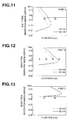
- Fig. 11 is a graph showing measurement results with respect to the flow rate of fluid at the point A in Fig. 9 and Fig. 10 , Fig.
- Fig. 12 is a graph showing measurement results with respect to the flow rate of fluid at the point B in Fig. 9 and Fig. 10
- Fig. 13 is a graph showing measurement results with respect to the flow rate of fluid at the point C in Fig. 9 and Fig. 10 .
- the endoscope 2 of the present embodiment can regulate a decrease in the flow rate of fluid ejected from the air/water feeding nozzle 19 in the vicinity of the second inclined face 23b at which the angle of elevation ⁇ 2 is enlarged of the inclined portion 23 whose external contour shape is an elliptical shape.
- a decrease in the flow rate of the fluid H2 on each of the second inclined face 23b sides that are orthogonal to the ejection direction of the air/water feeding nozzle 19 can be regulated to a significant degree relative to the flow rate of the fluid H1 that passes through the first inclined face 23a and passes through the center O of the observation window 15 that is illustrated in Fig. 8 .
- an air/water feeding action is performed in the manner described hereunder.
- a water feeding operation is performed so as to eject a flow of liquid such as water from the opening portion 24 of the air/water feeding nozzle 19 onto the observation window 15.
- a water feeding operation is performed, immediately after the liquid flow is ejected from the opening portion 24 of the air/water feeding nozzle 19, the liquid flow runs more easily onto the inclined face 23 having the gentle (small) inclination (slope) adjacent to the opening portion 24 than the center of the observation window 15 including the first inclined face 23a, and spreads out extensively to extend over the entire surface of the observation window 15.
- the liquid flow that has run over the observation window 15 converges to a width that is the same level as the width of the opening portion 24 of the air/water feeding nozzle 19 while descending the inclined portion 23 that is separated from the opening portion 24 more than the center of the observation window 15 including the second inclined face 23b and the first inclined face 23a that is a water feeding destination of the inclined portion 23.
- the second inclined face 23b that is orthogonal to the feeding direction of the liquid flow ejected from the air/water feeding nozzle 19 is set to the predetermined angle of elevation 82 which is a larger angle and has a steeper inclination (slope) than the predetermined angle of elevation ⁇ 1 of the first inclined face 23 whose inclination (slope) with respect to the flat portion 22 of the distal end portion 12 is gentle, a decrease in the flow rate of the liquid flow is lessened even at a place that is separated from the center O of the observation window 15 in a direction that is orthogonal to the feeding direction of the liquid flow. Consequently, dirt such as body fluid or mucous that attaches to the surface of the observation window 15 can be washed away easily by the liquid flow, and the cleanability of the entire surface of the observation window 15 improves.
- the endoscope 2 is switched from the water feeding operation to an air feeding operation, and air is fed from the opening portion 24 of the air/water feeding nozzle 19.
- air feeding is performed, water that remains on the surface of the observation window 15 is moved so as to be blown off the surface by the air.
- air ejected from the air/water feeding nozzle 19 flows more easily onto the inclined face 23 having the gentle inclination (slope) adjacent to the opening portion 24 than the center of the observation window 15 including the first inclined face 23a, and temporarily spreads over the entire surface of the observation window 15, and after passing over the surface of the observation window 15, tends to converge when descending the inclined portion 23 that is separated from the opening portion 24 more than the center of the observation window 15 including the second inclined face 23b and the first inclined face 23a that is the air feeding destination of the inclined portion 23.
- the second inclined face 23b that is orthogonal to the feeding direction of the air ejected from the air/water feeding nozzle 19 is set to the predetermined angle of elevation ⁇ 2 which is a larger angle and has a steeper inclination (slope) than the predetermined angle of elevation ⁇ 1 of the first inclined face 23a whose inclination (slope) with respect to the flat portion 22 of the distal end portion 12 is gentle, a decrease in the flow rate of the air is lessened even at a place that is separated from the center O of the observation window 15 in a direction that is orthogonal to the feeding direction of the air. Consequently, remaining water is easily blown off from the entire observation window 15 by the air feeding, and the water draining property of the observation window 15 improves.
- the observation window 15 is caused to protrude from the surface of the distal end portion 12, the inclined portion 23 whose external contour shape is an elliptical shape is formed around the observation window 15, it is easy for liquid and air that are fed in order to clean the observation window 15 to spread over the entire surface of the observation window 15, the manner in which liquid and air reach the surface of the observation window 15 is favorable, unwashed remnants of body fluid, mucous and the like that were attached to the distal end face of the observation window 15 are reduced thereby to improve the cleanability, and a water draining property with respect to water that remains after cleaning the observation window 15 by means of a liquid flow also improves.
- the planoconvex faces 25 that protrude with respect to the flat portion 22 are formed around the large illuminating window 17 and the small illuminating window 18 also. If the planoconvex faces 25 around the large illuminating window 17 and the small illuminating window 18 and the inclined face portion 23 formed around the observation window 15 were adjacent, a phenomenon would occur whereby a turbulent flow is generated in the fluid ejected from the air/water feeding nozzle 19 or whereby drops of water on the planoconvex faces 25 are drawn onto the surface of the observation window 15.
- the endoscope 2 of the present embodiment by adopting a configuration in which the shape of the inclined portion 23 around the observation window 15 is such that the external contour shape is an elliptical shape in which the outer diameter orthogonal to the ejection direction of fluid from the air/water feeding nozzle 19 is reduced, the distance by which the inclined portion 23, particularly the second inclined face 23b, is separated from the planoconvex faces 25 around the large illuminating window 17 and the small illuminating window 18 increases. In other words, the length of the flat portion 22 between the inclined portion 23, particularly the second inclined face 23b, and each planoconvex face 25 increases.
Landscapes
- Physics & Mathematics (AREA)
- Health & Medical Sciences (AREA)
- Life Sciences & Earth Sciences (AREA)
- Surgery (AREA)
- Optics & Photonics (AREA)
- Biomedical Technology (AREA)
- Public Health (AREA)
- Nuclear Medicine, Radiotherapy & Molecular Imaging (AREA)
- Pathology (AREA)
- Radiology & Medical Imaging (AREA)
- Veterinary Medicine (AREA)
- Engineering & Computer Science (AREA)
- Molecular Biology (AREA)
- Biophysics (AREA)
- Medical Informatics (AREA)
- Heart & Thoracic Surgery (AREA)
- Animal Behavior & Ethology (AREA)
- General Health & Medical Sciences (AREA)
- General Physics & Mathematics (AREA)
- Astronomy & Astrophysics (AREA)
- Endoscopes (AREA)
- Instruments For Viewing The Inside Of Hollow Bodies (AREA)
Abstract
Description
- The present invention relates to a structure of a distal end face of an insertion portion in an endoscope.
- Various technologies have been proposed for endoscopes which relate to the cleanability and water draining properties of an objective lens surface that serves as an observation window that is provided at a distal end portion of an endoscope.
- For example, Japanese Patent Application Laid-Open Publication No.
2011-120863 - Further, for example, Japanese Patent Application Laid-Open Publication No.
2011-255088 - However, in the configuration of the endoscope disclosed in Japanese Patent Application Laid-Open Publication No.
2011-120863 - In addition, since the observation window base portion is provided in the configuration of the endoscope disclosed in the Japanese Patent Application Laid-Open Publication No.
2011-255088 - The present invention has been achieved in view of the above-described problems, and an object of the present invention is to provide an endoscope which further improves cleanability and water draining property of an observation window composed of an objective lens.
- In order to achieve the above-described object, an endoscope according to one aspect of the present invention is an endoscope including a window portion and an air/water feeding nozzle at a distal end of an insertion portion, the endoscope including: a flat portion that is provided with the window portion and the air/water feeding nozzle; the window portion that protrudes by a predetermined height from the flat portion; the air/water feeding nozzle that is provided facing the window portion from the flat portion, and that ejects a fluid toward a surface of the window portion; and an inclined portion that is formed at a circumferential edge portion of the window portion; wherein, in angles of inclination with respect to the flat portion of the inclined portion, in comparison to a first angle of elevation that is an angle in a direction along a first axis that passes through a center of the window portion in an ejection direction of the fluid that is ejected from the air/water feeding nozzle, a second angle of elevation that is an angle in a direction along a second axis that is orthogonal to the first axis at the center of the window portion is made a larger angle.
- The endoscope of the present invention that is configured in this manner can further improve the cleanability and water draining property of the window portion.
-
-
Fig. 1 is an overall configuration diagram of an endoscope apparatus having an endoscope according to one aspect of the present invention; -
Fig. 2 is a front view of a distal end portion as seen from a distal end face side according to the aspect of the present invention; -
Fig. 3 is a cross-sectional view along a line III-III inFig. 2 according to the aspect of the present invention; -
Fig. 4 is a cross-sectional view along a line IV-O-IV inFig. 2 according to the aspect of the present invention; -
Fig. 5 is a plan view showing an air/water feeding nozzle and an observation window, which is a front view of the distal end portion as seen from the distal end face side according to the aspect of the present invention; -
Fig. 6 is a cross-sectional view along a line VI-VI inFig. 5 according to the aspect of the present invention; -
Fig. 7 is a cross-sectional view along a line VII-VII inFig. 5 according to the aspect of the present invention; -
Fig. 8 is a plan view showing an air/water feeding nozzle, an observation window, and an inclined portion according to the aspect of the present invention; -
Fig. 9 is a cross-sectional view of a distal end portion in which an inclined portion is a simple tapered structure according to the aspect of the present invention; -
Fig. 10 is a cross-sectional view of a distal end portion in which an inclined portion has the present configuration according to the aspect of the present invention; -
Fig. 11 is a graph showing a measurement result with respect to a flow rate of a fluid at a point A inFig. 9 and Fig. 10 according to the aspect of the present invention; -
Fig. 12 is a graph showing a measurement result with respect to a flow rate of a fluid at a point B inFig. 9 and Fig. 10 according to the aspect of the present invention; and -
Fig. 13 is a graph showing a measurement result with respect to a flow rate of a fluid at a point C inFig. 9 and Fig. 10 according to the aspect of the present invention. - Hereunder, an endoscope that is the present invention is described. It should be noted that, in the following description, drawings that are based on each embodiment are schematic ones in which a relationship between a thickness and a width of each portion, thickness ratios of the respective portions and the like are different from those of actual portions, and the drawings may include portions in which dimensional relationships and ratios are different from one another.
- An embodiment of the present invention is described hereunder with reference to the drawings.
-
Fig. 1 is an overall configuration diagram of an endoscope apparatus having the endoscope of the present invention. As shown inFig. 1 , an endoscope apparatus 1 includes, as principal parts, anendoscope 2, alight source apparatus 3 that supplies an illuminating light, avideo processor 4 that performs processing for an electrical signal that drives an image pickup apparatus to generate a video signal, and amonitor 5 that is a display apparatus that receives the video signal and displays an endoscopic image. - The
endoscope 2 includes aninsertion portion 6 that is inserted into a body cavity, anoperation portion 7, and auniversal cord 8. Aconnector 9 that is detachably connected to thelight source apparatus 3 is provided at a distal end of theuniversal cord 8 whose proximal end portion is coupled to theoperation portion 7. Anelectric cable 11 having, at a distal end portion, anelectrical connector 10 that is connected to thevideo processor 4 extends from theconnector 9. Theinsertion portion 6 includes adistal end portion 12, abending portion 13, and aflexible portion 14 that are connected in series in that order from the distal end side. -
Fig. 2 is a front view of the distal end portion as seen from the distal end face side. As shown inFig. 2 , as viewed facing of a paper surface, anobservation window 15 of a window portion including an objective lens is arranged toward an upper side, and asuction channel 16 is arranged toward a lower side on the distal end face of thedistal end portion 12. In addition, a largeilluminating window 17 including a large illumination lens is arranged toward a left side, and a smallilluminating window 18 including a small illumination lens is arranged toward a right side. Further, a discharge port of an air/water feeding nozzle 19 is arranged facing toward theobservation window 15 at a position that is adjacent to the upper side on the paper surface of the largeilluminating window 17. The aforementioned smallilluminating window 18 is provided adjacent to theobservation window 15 in a diagonally lower right direction. Further, a forwardwater feeding channel 27 is arranged in a vicinity of the largeilluminating window 17. -
Fig. 3 is a cross-sectional view along a line III-III inFig. 2 that shows a cross section from the air/water feeding nozzle 19 to theobservation window 15. As shown inFig. 3 , a distal endrigid member 20 that fixes an objectivelens support barrel 33 is provided in thedistal end portion 12, and adistal end cover 21 is covered thereon. Aflat portion 22 that forms a reference surface is formed on the distal end face of thedistal end cover 21. Theflat portion 22 occupies a major portion of the distal end face of theinsertion portion 6. Note that a distal-end constituent member of the present embodiment is formed by the distal endrigid member 20 and thedistal end cover 21. - A surface of the
observation window 15 protrudes, for example, by 0.3 mm with respect to theflat portion 22. In thedistal end cover 21 around theobservation window 15, aninclined portion 23 is provided from theflat portion 22 to a circumferential edge portion of theobservation window 15. In short, theinclined portion 23 that has a tapered shape toward the outer circumferential edge of theobservation window 15 is formed in thedistal end cover 21 around theobservation window 15. - An
opening portion 24 of the air/water feeding nozzle 19 is arranged so as to ride on theflat portion 22. Thesuction channel 16 is also provided in theflat portion 22 as shown inFig. 2 . An image pickup unit including an image pickup device and a lens group of an observation optical system (neither of which is illustrated in the drawings) are provided in theinsertion portion 6 on an inner side of theobservation window 15. - Note that, although in the present embodiment, a configuration is adopted in which the
observation window 15 is configured as a window portion that includes an objective lens, more specifically, an objective lens whose rear face (face on a proximal end side of the distal end portion 12) is a concave face and whose front face is a flat face, the present invention is not limited thereto, and the objective lens may be any combination of a rear face that is a concave face, a convex face, or a flat face and a front face that is a convex face or a flat face, and theobservation window 15 may also be a so-called "cover glass" in which both front and rear faces are flat faces. - Further, although in the present embodiment, the
flat portion 22 and theinclined portion 23 are provided in the distal end face of thedistal end cover 21, the present invention is not limited thereto, and for example, theflat portion 22 and theinclined portion 23 may be provided in the distal endrigid member 20 in an endoscope that does not have thedistal end cover 21, and furthermore, theinclined portion 23 may be formed by the objectivelens support barrel 33. -
Fig. 4 is a cross-sectional view along a line IV-O-IV inFig. 2 that shows a cross section from the largeilluminating window 17 to the smallilluminating window 18 that passes through a center O of theobservation window 15. The largeilluminating window 17 and the smallilluminating window 18 protrude, for example, by 0.3 mm with respect to theflat portion 22 that forms the reference surface, and have a height that is equal to that of theobservation window 15. - Planoconvex faces 25 that protrude, for example, by 0.3 mm with respect to the
flat portion 22 are also formed in thedistal end cover 21 around the largeilluminating window 17 and the smallilluminating window 18. In eachplanoconvex face 25, a boundary portion with the outer circumference of thedistal end cover 21 is R-chamfered, and aninclined wall 26 is formed at a boundary with theflat portion 22. - A configuration of the
inclined portion 23 of the present embodiment will now be described in detail. -
Fig. 5 is a plan view showing the air/water feeding nozzle and the observation window, which is a front view of the distal end portion as seen from the distal end face side. An external contour shape of theinclined portion 23 that is formed around theobservation window 15 is an elliptical shape whose diameter is expanded in a lateral direction (direction of a longitudinal axis that passes through the center O of theobservation window 15 along a Y-direction in the drawing, which may also be referred to as "Y-axis" in the following description) as viewed in the direction of the paper surface, and whose diameter is contracted in a vertical direction (short-axis direction that passes through the center O of theobservation window 15 along an X-direction in the drawing, which may also be referred to as "X-axis" in the following description). - The air/
water feeding nozzle 19 is disposed along the direction in which the diameter of theinclined portion 23 expands (Y-axis direction), and a fluid (a liquid flow for water feeding, air for air feeding or the like) from the air/water feeding nozzle 19 is ejected toward theobservation window 15. Note that the air/water feeding nozzle 19 is arranged so that the Y-axis that passes through the center O of theobservation window 15 passes through the center of the openingportion 24. - That is, the
inclined portion 23 is configured to have a firstinclined face 23a that is a face that slopes most gently from theflat portion 22 in the Y-axis direction that passes through the center O of theobservation window 15 along the ejection direction of the fluid from the air/water feeding nozzle 19, and a secondinclined face 23b that has a steeper slope than the firstinclined face 23a in the X-axis direction that passes through the center O of theobservation window 15 orthogonally to the ejection direction of the fluid from the air/water feeding nozzle 19. In theinclined portion 23, the secondinclined face 23b has the steepest inclination from theflat portion 22. - A structure of the
inclined portion 23 will now be described in further detail.Fig. 6 is a cross-sectional view along a line VI-VI inFig. 5 . As shown inFig. 6 , the firstinclined face 23a has a predetermined angle of elevation θ1 (angle formed by the firstinclined face 23a and the flat portion 22) at which the firstinclined face 23a inclines (slopes) from theflat portion 22. In contrast, as shown inFig. 7 that is a cross-sectional view along a line VII-VII inFig. 5 , a predetermined angle of elevation θ2 (angle formed by the secondinclined face 23b and the flat portion 22) at which the secondinclined face 23b inclines (slopes) from theflat portion 22 is set to a larger angle than the predetermined angle of elevation θ1 of the firstinclined face 23a (θ1 < θ2). - Here, the predetermined angle of elevation θ1 of the first
inclined face 23a is set to, for example, 25° ± 10°, and the predetermined angle of elevation θ2 of the secondinclined face 23b is set to, for example, 40° ± 10°. Note that a relationship between the predetermined angle of elevation θ1 of the firstinclined face 23a and the predetermined angle of elevation θ2 of the secondinclined face 23b is set so that the angle of elevation θ2 is always greater than the angle of elevation θ1 (θ1 < θ2). Further, a continuous slope (tapered face) is formed between the firstinclined face 23a and the secondinclined face 23b of theinclined portion 23 so that the slope between the respective predetermined angles of elevation θ1 and θ2 continuously changes. - According to the
endoscope 2 of the present embodiment configured as described above, the configuration is such that fluid is ejected from the air/water feeding nozzle 19, and the fluid spreads out over the entire surface of theobservation window 15 by means of theinclined portion 23.Fig. 8 is a plan view illustrating the air/water feeding nozzle, the observation window, and the inclined portion. As shown inFig. 8 , the flow rate of fluid H1 that passes over the firstinclined face 23a and through the center O of theobservation window 15 is the fastest among the fluid from the air/water feeding nozzle 19. On the other hand, because fluid H2 on each of the secondinclined face 23b sides that are orthogonal to the ejection direction of the air/water feeding nozzle 19 is separated by a long distance from the center O of theobservation window 15, among the fluid from the air/water feeding nozzle 19, the flow rate of the fluid H2 is inevitably slower than that of the fluid H1. In addition, for example, in a case where θ1 = θ2 in which the angle of elevation θ2 of the secondinclined face 23b is identical to the first angle of elevation θ1, in comparison to the case where θ1 < θ2, the cross-sectional area of the secondinclined face 23b would increase and would be liable to act as a barrier to the fluid H2, and thus the flow rate of the fluid H2 would be slower. - Therefore, as described above, according to the
endoscope 2 of the present embodiment, in theinclined portion 23 that is formed at an edge portion around theobservation window 15, the secondinclined face 23b that is orthogonal to the ejection direction of the air/water feeding nozzle 19 is caused to incline (slope) more than the firstinclined face 23a along the ejection direction of the air/water feeding nozzle 19, and a structure in which the cross-sectional area on the secondinclined face 23b side is made smaller than the cross-sectional area on the firstinclined face 23a, and not a simple tapered structure, and hence a decrease in the flow rate of the fluid H2 on the secondinclined face 23b side is lessened (regulated). - That is, at the
inclined portion 23 and theobservation window 15, in the cross-sectional area that protrudes from theflat portion 22 along an axis that passes through the center O of theobservation window 15, a cross-sectional area on the secondinclined face 23b side that is orthogonal to the ejection direction of the air/water feeding nozzle 19 is smaller than a cross-sectional area on the firstinclined face 23a side that is the ejection direction of the air/water feeding nozzle 19. Therefore, a reduction in the flow rate of the fluid H2 on the secondinclined face 23b side can be lessened (regulated). -
Fig. 9 is a cross-sectional view of a distal end portion in a case where an inclined portion is a simple tapered structure, andFig. 10 is a cross-sectional view of the distal end portion of the inclined portion that has the present configuration. The flow rate of fluid from the air/water feeding nozzle 19 in the case where, as shown inFig. 10 , the predetermined angle of elevation θ2 of the secondinclined face 23b is made larger than the predetermined angle of elevation θ1 of the firstinclined face 23a (θ1 < θ2) that is the present configuration was measured with respect to the flow rate of fluid from the air/water feeding nozzle 19 in a case where a simple tapered structure was adopted in which, for example, as shown inFig. 9 , at theinclined portion 23, the predetermined angle of elevation θ2 of the secondinclined face 23b was made the same angle as the predetermined angle of elevation θ1 of the firstinclined face 23a (θ1 = θ2). - Note that, as shown in
Fig. 9 and Fig. 10 , the flow rate of fluid was measured at three places on the secondinclined face 23b, namely, a point A at a boundary portion (vicinity of a base) with respect to theflat portion 22, a point B at approximately a center portion, and a point C at a boundary portion (vicinity of an apex) with respect to theobservation window 15. - As shown in
Fig. 11 to Fig. 13 , results were obtained that showed that in comparison to the configuration in which theinclined portion 23 is formed to have a simple tapered structure as shown inFig. 9 , in the case of theinclined portion 23 according to the present configuration in which the predetermined angle of elevation θ2 of the secondinclined face 23b is made larger than the predetermined angle of elevation θ1 of the firstinclined face 23a (θ1 < θ2), the flow rate of fluid from the air/water feeding nozzle 19 is clearly faster at each of the three measurement points A, B and C. Note thatFig. 11 is a graph showing measurement results with respect to the flow rate of fluid at the point A inFig. 9 and Fig. 10 ,Fig. 12 is a graph showing measurement results with respect to the flow rate of fluid at the point B inFig. 9 and Fig. 10 , andFig. 13 is a graph showing measurement results with respect to the flow rate of fluid at the point C inFig. 9 and Fig. 10 . - More specifically, as shown in
Fig. 11 , with respect to the point A, a result was obtained to the effect that in the case of the configuration of theinclined portion 23 of the present configuration, the flow rate of fluid becomes faster than that of the simple tapered structure from a position at which a height from a lens face of theobservation window 15 is around -0.20 mm, and thereafter the flow rate of the fluid is faster than that of the simple tapered structure even after passing a height of 0.15 mm from the lens face of theobservation window 15. - Further, as shown in
Fig. 12 , with respect to the point B also, a result was obtained to the effect that in the case of the configuration of theinclined portion 23 of the present embodiment, the flow rate of fluid becomes faster than that of the simple tapered structure from a position at which the height from the lens face of theobservation window 15 is around -0.12 mm, and thereafter the flow rate of the fluid is faster than that of the simple tapered structure even after passing the height of 0.15 mm from the lens face of theobservation window 15. - Furthermore, as shown in
Fig. 13 , with respect to the point C also, a result was obtained to the effect that in the case of the configuration of theinclined portion 23 of the present embodiment, the flow rate of fluid becomes faster than that of the simple tapered structure from a position at which the height from the lens face of theobservation window 15 is around 0.02 mm, and the flow rate of the fluid converges toward the same rate as that of the simple tapered structure from around a position at which the height of 0.15 mm from the lens face of theobservation window 15 is passed. - Based on the foregoing, results are obtained to the effect that, in comparison to a simple tapered structure, the
endoscope 2 of the present embodiment can regulate a decrease in the flow rate of fluid ejected from the air/water feeding nozzle 19 in the vicinity of the secondinclined face 23b at which the angle of elevation θ2 is enlarged of theinclined portion 23 whose external contour shape is an elliptical shape. In other words, of the fluid ejected from the air/water feeding nozzle 19, a decrease in the flow rate of the fluid H2 on each of the secondinclined face 23b sides that are orthogonal to the ejection direction of the air/water feeding nozzle 19 can be regulated to a significant degree relative to the flow rate of the fluid H1 that passes through the firstinclined face 23a and passes through the center O of theobservation window 15 that is illustrated inFig. 8 . - In this case, in the
endoscope 2 of the present embodiment, an air/water feeding action is performed in the manner described hereunder. - First, in order to clean the
observation window 15, in theendoscope 2, a water feeding operation is performed so as to eject a flow of liquid such as water from the openingportion 24 of the air/water feeding nozzle 19 onto theobservation window 15. When this water feeding is performed, immediately after the liquid flow is ejected from the openingportion 24 of the air/water feeding nozzle 19, the liquid flow runs more easily onto theinclined face 23 having the gentle (small) inclination (slope) adjacent to the openingportion 24 than the center of theobservation window 15 including the firstinclined face 23a, and spreads out extensively to extend over the entire surface of theobservation window 15. Subsequently, the liquid flow that has run over theobservation window 15 converges to a width that is the same level as the width of the openingportion 24 of the air/water feeding nozzle 19 while descending theinclined portion 23 that is separated from the openingportion 24 more than the center of theobservation window 15 including the secondinclined face 23b and the firstinclined face 23a that is a water feeding destination of theinclined portion 23. - At this time, at the
inclined portion 23 whose external contour shape is an elliptical shape of theendoscope 2, since the secondinclined face 23b that is orthogonal to the feeding direction of the liquid flow ejected from the air/water feeding nozzle 19 is set to the predetermined angle ofelevation 82 which is a larger angle and has a steeper inclination (slope) than the predetermined angle of elevation θ1 of the firstinclined face 23 whose inclination (slope) with respect to theflat portion 22 of thedistal end portion 12 is gentle, a decrease in the flow rate of the liquid flow is lessened even at a place that is separated from the center O of theobservation window 15 in a direction that is orthogonal to the feeding direction of the liquid flow. Consequently, dirt such as body fluid or mucous that attaches to the surface of theobservation window 15 can be washed away easily by the liquid flow, and the cleanability of the entire surface of theobservation window 15 improves. - Next, the
endoscope 2 is switched from the water feeding operation to an air feeding operation, and air is fed from the openingportion 24 of the air/water feeding nozzle 19. When the air feeding is performed, water that remains on the surface of theobservation window 15 is moved so as to be blown off the surface by the air. - That is, similarly to when performing water feeding, air ejected from the air/
water feeding nozzle 19 flows more easily onto theinclined face 23 having the gentle inclination (slope) adjacent to the openingportion 24 than the center of theobservation window 15 including the firstinclined face 23a, and temporarily spreads over the entire surface of theobservation window 15, and after passing over the surface of theobservation window 15, tends to converge when descending theinclined portion 23 that is separated from the openingportion 24 more than the center of theobservation window 15 including the secondinclined face 23b and the firstinclined face 23a that is the air feeding destination of theinclined portion 23. - Consequently, when the operation is switched from water feeding to air feeding, drops of water on the surface of the
observation window 15 spread out in a radial shape while moving so as to be blown off in mainly the air feeding direction, and are thus drained from the surface of theobservation window 15. - At this time also, at the
inclined portion 23 whose external contour shape is an elliptical shape of theendoscope 2, since the secondinclined face 23b that is orthogonal to the feeding direction of the air ejected from the air/water feeding nozzle 19 is set to the predetermined angle of elevation θ2 which is a larger angle and has a steeper inclination (slope) than the predetermined angle of elevation θ1 of the firstinclined face 23a whose inclination (slope) with respect to theflat portion 22 of thedistal end portion 12 is gentle, a decrease in the flow rate of the air is lessened even at a place that is separated from the center O of theobservation window 15 in a direction that is orthogonal to the feeding direction of the air. Consequently, remaining water is easily blown off from theentire observation window 15 by the air feeding, and the water draining property of theobservation window 15 improves. - Thus, according to the
endoscope 2 of the present embodiment, theobservation window 15 is caused to protrude from the surface of thedistal end portion 12, theinclined portion 23 whose external contour shape is an elliptical shape is formed around theobservation window 15, it is easy for liquid and air that are fed in order to clean theobservation window 15 to spread over the entire surface of theobservation window 15, the manner in which liquid and air reach the surface of theobservation window 15 is favorable, unwashed remnants of body fluid, mucous and the like that were attached to the distal end face of theobservation window 15 are reduced thereby to improve the cleanability, and a water draining property with respect to water that remains after cleaning theobservation window 15 by means of a liquid flow also improves. - Further, as shown in
Fig. 2 and Fig. 4 , the planoconvex faces 25 that protrude with respect to theflat portion 22 are formed around the large illuminatingwindow 17 and the small illuminatingwindow 18 also. If the planoconvex faces 25 around the large illuminatingwindow 17 and the small illuminatingwindow 18 and theinclined face portion 23 formed around theobservation window 15 were adjacent, a phenomenon would occur whereby a turbulent flow is generated in the fluid ejected from the air/water feeding nozzle 19 or whereby drops of water on the planoconvex faces 25 are drawn onto the surface of theobservation window 15. - However, according to the
endoscope 2 of the present embodiment, by adopting a configuration in which the shape of theinclined portion 23 around theobservation window 15 is such that the external contour shape is an elliptical shape in which the outer diameter orthogonal to the ejection direction of fluid from the air/water feeding nozzle 19 is reduced, the distance by which theinclined portion 23, particularly the secondinclined face 23b, is separated from the planoconvex faces 25 around the large illuminatingwindow 17 and the small illuminatingwindow 18 increases. In other words, the length of theflat portion 22 between theinclined portion 23, particularly the secondinclined face 23b, and eachplanoconvex face 25 increases. - According to this configuration, since the
inclined face portion 23 formed around theobservation window 15 and the planoconvex faces 25 around the large illuminatingwindow 17 and the small illuminatingwindow 18 do not come close to each other and a predetermined separation distance can be maintained therebetween, the occurrence of a phenomenon whereby a turbulent flow is generated in the fluid ejected from the air/water feeding nozzle 19 or whereby drops of water on the planoconvex faces 25 are drawn onto the surface of theobservation window 15 can be reduced. - Note that the invention described in the foregoing embodiment is not limited to the embodiment and modification described above, and various modifications can be implemented within a range that does not deviate from the spirit and scope of the present invention in the implementing stage. Further, the above described embodiment includes inventions of various stages, and various inventions can be extracted by appropriately combining a plurality of the disclosed configuration requirements.
- For example, if a problem to be solved by the invention can be solved and the described effects of the invention are obtained even after omitting some of the configuration requirements from the entire configuration requirements shown in the embodiment, then the configuration obtained by omitting the configuration requirements can be extracted as an invention.
- The present application is filed claiming the priority of Japanese Patent Application No.
2012-184348
Claims (7)
- An endoscope including a window portion and an air/water feeding nozzle at a distal end of an insertion portion, the endoscope comprising:a flat portion that is provided with the window portion and the air/water feeding nozzle;the window portion that protrudes by a predetermined height from the flat portion;the air/water feeding nozzle that is provided facing the window portion from the flat portion, and that ejects a fluid toward a surface of the window portion; andan inclined portion that is formed at a circumferential edge portion of the window portion;wherein, in angles of inclination with respect to the flat portion of the inclined portion, in comparison to a first angle of elevation that is an angle in a direction along a first axis that passes through a center of the window portion in an ejection direction of the fluid that is ejected from the air/water feeding nozzle, a second angle of elevation that is an angle in a direction along a second axis that is orthogonal to the first axis at the center of the window portion is made a larger angle.
- The endoscope according to claim 1, wherein, with respect to the inclined portion, a cross-sectional area in a direction along the second axis is made smaller than a cross-sectional area in a direction along the first axis.
- The endoscope according to claim 1 or 2, wherein, with respect to a cross-sectional area comprising the inclined portion and the window portion, a cross-sectional area of a portion protruding from the flat portion in a direction along the second axis is made smaller than a cross-sectional area in a direction along the first axis.
- The endoscope according to any one of claims 1 to 3, wherein the window portion is an observation window for observation that has an objective lens.
- The endoscope according to any one of claims 1 to 4, wherein:the window portion is formed in a circular surface shape; andan external contour shape of the inclined portion is an elliptical shape.
- The endoscope according to claim 5, wherein the air/water feeding nozzle is disposed so as to eject the fluid in a longitudinal axis direction of the elliptical inclined portion.
- The endoscope according to any one of claims 1 to 6, wherein a continuous inclined face is formed between the first angle of elevation and the second angle of elevation of the inclined portion.
Applications Claiming Priority (2)
| Application Number | Priority Date | Filing Date | Title |
|---|---|---|---|
| JP2012184348 | 2012-08-23 | ||
| PCT/JP2013/060958 WO2014030385A1 (en) | 2012-08-23 | 2013-04-11 | Endoscope |
Publications (3)
| Publication Number | Publication Date |
|---|---|
| EP2735260A1 true EP2735260A1 (en) | 2014-05-28 |
| EP2735260A4 EP2735260A4 (en) | 2015-05-13 |
| EP2735260B1 EP2735260B1 (en) | 2019-06-05 |
Family
ID=50149705
Family Applications (1)
| Application Number | Title | Priority Date | Filing Date |
|---|---|---|---|
| EP13818970.9A Active EP2735260B1 (en) | 2012-08-23 | 2013-04-11 | Endoscope |
Country Status (5)
| Country | Link |
|---|---|
| US (1) | US20140094659A1 (en) |
| EP (1) | EP2735260B1 (en) |
| JP (1) | JP5433116B1 (en) |
| CN (1) | CN103813744B (en) |
| WO (1) | WO2014030385A1 (en) |
Families Citing this family (13)
| Publication number | Priority date | Publication date | Assignee | Title |
|---|---|---|---|---|
| WO2015077584A2 (en) | 2013-11-22 | 2015-05-28 | Massachusetts Institute Of Technology | Steering techniques for surgical instruments |
| US10542868B2 (en) | 2014-09-10 | 2020-01-28 | Intuitive Surgical Operations, Inc. | Devices, systems, and methods using mating catheter tips and tools |
| EP3200704B1 (en) * | 2014-09-30 | 2020-05-20 | Massachusetts Institute of Technology | Instruments for minimally invasive surgical procedures |
| JP6368276B2 (en) | 2015-04-24 | 2018-08-01 | 富士フイルム株式会社 | Endoscope |
| WO2018179791A1 (en) * | 2017-03-31 | 2018-10-04 | Hoya株式会社 | Endoscope |
| JPWO2018179792A1 (en) * | 2017-03-31 | 2019-11-07 | Hoya株式会社 | Endoscope |
| US20180289248A1 (en) * | 2017-04-06 | 2018-10-11 | Everich Biotecology Corporation | Cleaning structure for endoscope lens |
| JP6830876B2 (en) * | 2017-09-22 | 2021-02-17 | 富士フイルム株式会社 | Endoscope |
| JP6849567B2 (en) * | 2017-09-28 | 2021-03-24 | 富士フイルム株式会社 | Endoscope |
| WO2021035051A1 (en) * | 2019-08-22 | 2021-02-25 | Fraen Corporation | Optical system having tapered light transmission element |
| DE102021114984A1 (en) * | 2021-06-10 | 2022-12-15 | Hoya Corporation | Endoscope with nozzle element for cleaning a lens element |
| US12543937B2 (en) * | 2021-10-08 | 2026-02-10 | Olympus Medical Systems Corp. | Endoscope |
| US12035886B2 (en) | 2022-02-04 | 2024-07-16 | Olympus Medical Systems Corp. | Endoscope, insertion portion and distal-end constituting portion for use with endoscope |
Family Cites Families (6)
| Publication number | Priority date | Publication date | Assignee | Title |
|---|---|---|---|---|
| JP3845311B2 (en) * | 2002-01-21 | 2006-11-15 | オリンパス株式会社 | Endoscope |
| JP4451316B2 (en) * | 2005-01-07 | 2010-04-14 | オリンパスメディカルシステムズ株式会社 | Endoscope insertion part and endoscope |
| JP4754871B2 (en) * | 2005-05-11 | 2011-08-24 | オリンパスメディカルシステムズ株式会社 | End of the endoscope |
| JP2011120863A (en) * | 2009-11-11 | 2011-06-23 | Fujifilm Corp | Endoscope |
| JP5554153B2 (en) | 2010-06-11 | 2014-07-23 | 富士フイルム株式会社 | Endoscope |
| JP5261518B2 (en) * | 2011-03-01 | 2013-08-14 | 富士フイルム株式会社 | Endoscope |
-
2013
- 2013-04-11 CN CN201380002530.3A patent/CN103813744B/en active Active
- 2013-04-11 JP JP2013546479A patent/JP5433116B1/en active Active
- 2013-04-11 EP EP13818970.9A patent/EP2735260B1/en active Active
- 2013-04-11 WO PCT/JP2013/060958 patent/WO2014030385A1/en not_active Ceased
- 2013-10-21 US US14/058,453 patent/US20140094659A1/en not_active Abandoned
Also Published As
| Publication number | Publication date |
|---|---|
| US20140094659A1 (en) | 2014-04-03 |
| CN103813744B (en) | 2016-09-07 |
| WO2014030385A1 (en) | 2014-02-27 |
| JPWO2014030385A1 (en) | 2016-07-28 |
| JP5433116B1 (en) | 2014-03-05 |
| EP2735260A4 (en) | 2015-05-13 |
| EP2735260B1 (en) | 2019-06-05 |
| CN103813744A (en) | 2014-05-21 |
Similar Documents
| Publication | Publication Date | Title |
|---|---|---|
| EP2735260B1 (en) | Endoscope | |
| US9943217B2 (en) | Endoscope | |
| KR101556881B1 (en) | Endoscope | |
| EP2859835B1 (en) | Endoscope | |
| JP5670000B1 (en) | End member of medical device, endoscope cleaning sheath, and endoscope system using this endoscope cleaning sheath | |
| CN106063697A (en) | endoscope | |
| US20200000320A1 (en) | Endoscope | |
| US11042020B2 (en) | Endoscope having observation window with circumferential side surface and cleaning nozzles directed to circumferential side surface | |
| US20190350449A1 (en) | Endoscope | |
| JP6091219B2 (en) | Endoscope device | |
| US9220397B2 (en) | Endoscope | |
| JP6430739B2 (en) | Endoscope | |
| JP6165396B1 (en) | Endoscope | |
| CN119586944A (en) | Endoscope | |
| JP5639234B2 (en) | Endoscope | |
| WO2013132684A1 (en) | Endoscope |
Legal Events
| Date | Code | Title | Description |
|---|---|---|---|
| PUAI | Public reference made under article 153(3) epc to a published international application that has entered the european phase |
Free format text: ORIGINAL CODE: 0009012 |
|
| 17P | Request for examination filed |
Effective date: 20140123 |
|
| AK | Designated contracting states |
Kind code of ref document: A1 Designated state(s): AL AT BE BG CH CY CZ DE DK EE ES FI FR GB GR HR HU IE IS IT LI LT LU LV MC MK MT NL NO PL PT RO RS SE SI SK SM TR |
|
| RA4 | Supplementary search report drawn up and despatched (corrected) |
Effective date: 20150414 |
|
| RAP1 | Party data changed (applicant data changed or rights of an application transferred) |
Owner name: OLYMPUS CORPORATION |
|
| DAX | Request for extension of the european patent (deleted) | ||
| RAP1 | Party data changed (applicant data changed or rights of an application transferred) |
Owner name: OLYMPUS CORPORATION |
|
| RAP1 | Party data changed (applicant data changed or rights of an application transferred) |
Owner name: OLYMPUS CORPORATION |
|
| RIN1 | Information on inventor provided before grant (corrected) |
Inventor name: WATANABE, TAKANORI Inventor name: HAMAZAKI, MASANORI |
|
| GRAP | Despatch of communication of intention to grant a patent |
Free format text: ORIGINAL CODE: EPIDOSNIGR1 |
|
| STAA | Information on the status of an ep patent application or granted ep patent |
Free format text: STATUS: GRANT OF PATENT IS INTENDED |
|
| INTG | Intention to grant announced |
Effective date: 20181129 |
|
| GRAS | Grant fee paid |
Free format text: ORIGINAL CODE: EPIDOSNIGR3 |
|
| GRAA | (expected) grant |
Free format text: ORIGINAL CODE: 0009210 |
|
| STAA | Information on the status of an ep patent application or granted ep patent |
Free format text: STATUS: THE PATENT HAS BEEN GRANTED |
|
| AK | Designated contracting states |
Kind code of ref document: B1 Designated state(s): AL AT BE BG CH CY CZ DE DK EE ES FI FR GB GR HR HU IE IS IT LI LT LU LV MC MK MT NL NO PL PT RO RS SE SI SK SM TR |
|
| REG | Reference to a national code |
Ref country code: GB Ref legal event code: FG4D |
|
| REG | Reference to a national code |
Ref country code: CH Ref legal event code: EP |
|
| REG | Reference to a national code |
Ref country code: AT Ref legal event code: REF Ref document number: 1139167 Country of ref document: AT Kind code of ref document: T Effective date: 20190615 |
|
| REG | Reference to a national code |
Ref country code: DE Ref legal event code: R096 Ref document number: 602013056291 Country of ref document: DE |
|
| REG | Reference to a national code |
Ref country code: IE Ref legal event code: FG4D |
|
| REG | Reference to a national code |
Ref country code: NL Ref legal event code: MP Effective date: 20190605 |
|
| REG | Reference to a national code |
Ref country code: LT Ref legal event code: MG4D |
|
| PG25 | Lapsed in a contracting state [announced via postgrant information from national office to epo] |
Ref country code: NO Free format text: LAPSE BECAUSE OF FAILURE TO SUBMIT A TRANSLATION OF THE DESCRIPTION OR TO PAY THE FEE WITHIN THE PRESCRIBED TIME-LIMIT Effective date: 20190905 Ref country code: LT Free format text: LAPSE BECAUSE OF FAILURE TO SUBMIT A TRANSLATION OF THE DESCRIPTION OR TO PAY THE FEE WITHIN THE PRESCRIBED TIME-LIMIT Effective date: 20190605 Ref country code: ES Free format text: LAPSE BECAUSE OF FAILURE TO SUBMIT A TRANSLATION OF THE DESCRIPTION OR TO PAY THE FEE WITHIN THE PRESCRIBED TIME-LIMIT Effective date: 20190605 Ref country code: HR Free format text: LAPSE BECAUSE OF FAILURE TO SUBMIT A TRANSLATION OF THE DESCRIPTION OR TO PAY THE FEE WITHIN THE PRESCRIBED TIME-LIMIT Effective date: 20190605 Ref country code: SE Free format text: LAPSE BECAUSE OF FAILURE TO SUBMIT A TRANSLATION OF THE DESCRIPTION OR TO PAY THE FEE WITHIN THE PRESCRIBED TIME-LIMIT Effective date: 20190605 Ref country code: AL Free format text: LAPSE BECAUSE OF FAILURE TO SUBMIT A TRANSLATION OF THE DESCRIPTION OR TO PAY THE FEE WITHIN THE PRESCRIBED TIME-LIMIT Effective date: 20190605 Ref country code: FI Free format text: LAPSE BECAUSE OF FAILURE TO SUBMIT A TRANSLATION OF THE DESCRIPTION OR TO PAY THE FEE WITHIN THE PRESCRIBED TIME-LIMIT Effective date: 20190605 |
|
| PG25 | Lapsed in a contracting state [announced via postgrant information from national office to epo] |
Ref country code: RS Free format text: LAPSE BECAUSE OF FAILURE TO SUBMIT A TRANSLATION OF THE DESCRIPTION OR TO PAY THE FEE WITHIN THE PRESCRIBED TIME-LIMIT Effective date: 20190605 Ref country code: LV Free format text: LAPSE BECAUSE OF FAILURE TO SUBMIT A TRANSLATION OF THE DESCRIPTION OR TO PAY THE FEE WITHIN THE PRESCRIBED TIME-LIMIT Effective date: 20190605 Ref country code: GR Free format text: LAPSE BECAUSE OF FAILURE TO SUBMIT A TRANSLATION OF THE DESCRIPTION OR TO PAY THE FEE WITHIN THE PRESCRIBED TIME-LIMIT Effective date: 20190906 Ref country code: BG Free format text: LAPSE BECAUSE OF FAILURE TO SUBMIT A TRANSLATION OF THE DESCRIPTION OR TO PAY THE FEE WITHIN THE PRESCRIBED TIME-LIMIT Effective date: 20190905 |
|
| REG | Reference to a national code |
Ref country code: AT Ref legal event code: MK05 Ref document number: 1139167 Country of ref document: AT Kind code of ref document: T Effective date: 20190605 |
|
| PG25 | Lapsed in a contracting state [announced via postgrant information from national office to epo] |
Ref country code: CZ Free format text: LAPSE BECAUSE OF FAILURE TO SUBMIT A TRANSLATION OF THE DESCRIPTION OR TO PAY THE FEE WITHIN THE PRESCRIBED TIME-LIMIT Effective date: 20190605 Ref country code: SK Free format text: LAPSE BECAUSE OF FAILURE TO SUBMIT A TRANSLATION OF THE DESCRIPTION OR TO PAY THE FEE WITHIN THE PRESCRIBED TIME-LIMIT Effective date: 20190605 Ref country code: RO Free format text: LAPSE BECAUSE OF FAILURE TO SUBMIT A TRANSLATION OF THE DESCRIPTION OR TO PAY THE FEE WITHIN THE PRESCRIBED TIME-LIMIT Effective date: 20190605 Ref country code: AT Free format text: LAPSE BECAUSE OF FAILURE TO SUBMIT A TRANSLATION OF THE DESCRIPTION OR TO PAY THE FEE WITHIN THE PRESCRIBED TIME-LIMIT Effective date: 20190605 Ref country code: PT Free format text: LAPSE BECAUSE OF FAILURE TO SUBMIT A TRANSLATION OF THE DESCRIPTION OR TO PAY THE FEE WITHIN THE PRESCRIBED TIME-LIMIT Effective date: 20191007 Ref country code: NL Free format text: LAPSE BECAUSE OF FAILURE TO SUBMIT A TRANSLATION OF THE DESCRIPTION OR TO PAY THE FEE WITHIN THE PRESCRIBED TIME-LIMIT Effective date: 20190605 Ref country code: EE Free format text: LAPSE BECAUSE OF FAILURE TO SUBMIT A TRANSLATION OF THE DESCRIPTION OR TO PAY THE FEE WITHIN THE PRESCRIBED TIME-LIMIT Effective date: 20190605 |
|
| PG25 | Lapsed in a contracting state [announced via postgrant information from national office to epo] |
Ref country code: IS Free format text: LAPSE BECAUSE OF FAILURE TO SUBMIT A TRANSLATION OF THE DESCRIPTION OR TO PAY THE FEE WITHIN THE PRESCRIBED TIME-LIMIT Effective date: 20191005 Ref country code: SM Free format text: LAPSE BECAUSE OF FAILURE TO SUBMIT A TRANSLATION OF THE DESCRIPTION OR TO PAY THE FEE WITHIN THE PRESCRIBED TIME-LIMIT Effective date: 20190605 Ref country code: IT Free format text: LAPSE BECAUSE OF FAILURE TO SUBMIT A TRANSLATION OF THE DESCRIPTION OR TO PAY THE FEE WITHIN THE PRESCRIBED TIME-LIMIT Effective date: 20190605 |
|
| REG | Reference to a national code |
Ref country code: DE Ref legal event code: R097 Ref document number: 602013056291 Country of ref document: DE |
|
| PG25 | Lapsed in a contracting state [announced via postgrant information from national office to epo] |
Ref country code: TR Free format text: LAPSE BECAUSE OF FAILURE TO SUBMIT A TRANSLATION OF THE DESCRIPTION OR TO PAY THE FEE WITHIN THE PRESCRIBED TIME-LIMIT Effective date: 20190605 |
|
| PLBE | No opposition filed within time limit |
Free format text: ORIGINAL CODE: 0009261 |
|
| STAA | Information on the status of an ep patent application or granted ep patent |
Free format text: STATUS: NO OPPOSITION FILED WITHIN TIME LIMIT |
|
| PG25 | Lapsed in a contracting state [announced via postgrant information from national office to epo] |
Ref country code: PL Free format text: LAPSE BECAUSE OF FAILURE TO SUBMIT A TRANSLATION OF THE DESCRIPTION OR TO PAY THE FEE WITHIN THE PRESCRIBED TIME-LIMIT Effective date: 20190605 Ref country code: DK Free format text: LAPSE BECAUSE OF FAILURE TO SUBMIT A TRANSLATION OF THE DESCRIPTION OR TO PAY THE FEE WITHIN THE PRESCRIBED TIME-LIMIT Effective date: 20190605 |
|
| 26N | No opposition filed |
Effective date: 20200306 |
|
| PG25 | Lapsed in a contracting state [announced via postgrant information from national office to epo] |
Ref country code: SI Free format text: LAPSE BECAUSE OF FAILURE TO SUBMIT A TRANSLATION OF THE DESCRIPTION OR TO PAY THE FEE WITHIN THE PRESCRIBED TIME-LIMIT Effective date: 20190605 |
|
| REG | Reference to a national code |
Ref country code: DE Ref legal event code: R119 Ref document number: 602013056291 Country of ref document: DE |
|
| PG25 | Lapsed in a contracting state [announced via postgrant information from national office to epo] |
Ref country code: MC Free format text: LAPSE BECAUSE OF FAILURE TO SUBMIT A TRANSLATION OF THE DESCRIPTION OR TO PAY THE FEE WITHIN THE PRESCRIBED TIME-LIMIT Effective date: 20190605 |
|
| REG | Reference to a national code |
Ref country code: CH Ref legal event code: PL |
|
| PG25 | Lapsed in a contracting state [announced via postgrant information from national office to epo] |
Ref country code: LI Free format text: LAPSE BECAUSE OF NON-PAYMENT OF DUE FEES Effective date: 20200430 Ref country code: FR Free format text: LAPSE BECAUSE OF NON-PAYMENT OF DUE FEES Effective date: 20200430 Ref country code: CH Free format text: LAPSE BECAUSE OF NON-PAYMENT OF DUE FEES Effective date: 20200430 Ref country code: LU Free format text: LAPSE BECAUSE OF NON-PAYMENT OF DUE FEES Effective date: 20200411 Ref country code: DE Free format text: LAPSE BECAUSE OF NON-PAYMENT OF DUE FEES Effective date: 20201103 |
|
| REG | Reference to a national code |
Ref country code: BE Ref legal event code: MM Effective date: 20200430 |
|
| PG25 | Lapsed in a contracting state [announced via postgrant information from national office to epo] |
Ref country code: BE Free format text: LAPSE BECAUSE OF NON-PAYMENT OF DUE FEES Effective date: 20200430 |
|
| GBPC | Gb: european patent ceased through non-payment of renewal fee |
Effective date: 20200411 |
|
| PG25 | Lapsed in a contracting state [announced via postgrant information from national office to epo] |
Ref country code: IE Free format text: LAPSE BECAUSE OF NON-PAYMENT OF DUE FEES Effective date: 20200411 Ref country code: GB Free format text: LAPSE BECAUSE OF NON-PAYMENT OF DUE FEES Effective date: 20200411 |
|
| PG25 | Lapsed in a contracting state [announced via postgrant information from national office to epo] |
Ref country code: MT Free format text: LAPSE BECAUSE OF FAILURE TO SUBMIT A TRANSLATION OF THE DESCRIPTION OR TO PAY THE FEE WITHIN THE PRESCRIBED TIME-LIMIT Effective date: 20190605 Ref country code: CY Free format text: LAPSE BECAUSE OF FAILURE TO SUBMIT A TRANSLATION OF THE DESCRIPTION OR TO PAY THE FEE WITHIN THE PRESCRIBED TIME-LIMIT Effective date: 20190605 |
|
| PG25 | Lapsed in a contracting state [announced via postgrant information from national office to epo] |
Ref country code: MK Free format text: LAPSE BECAUSE OF FAILURE TO SUBMIT A TRANSLATION OF THE DESCRIPTION OR TO PAY THE FEE WITHIN THE PRESCRIBED TIME-LIMIT Effective date: 20190605 |