EP2735258B1 - Medical device - Google Patents
Medical device Download PDFInfo
- Publication number
- EP2735258B1 EP2735258B1 EP12830813.7A EP12830813A EP2735258B1 EP 2735258 B1 EP2735258 B1 EP 2735258B1 EP 12830813 A EP12830813 A EP 12830813A EP 2735258 B1 EP2735258 B1 EP 2735258B1
- Authority
- EP
- European Patent Office
- Prior art keywords
- magnetic field
- static magnetic
- capsule endoscope
- medical device
- sets
- Prior art date
- Legal status (The legal status is an assumption and is not a legal conclusion. Google has not performed a legal analysis and makes no representation as to the accuracy of the status listed.)
- Not-in-force
Links
- 239000002775 capsule Substances 0.000 claims description 130
- 230000003068 static effect Effects 0.000 claims description 73
- 230000008859 change Effects 0.000 claims description 18
- 230000001141 propulsive effect Effects 0.000 claims description 14
- 230000005415 magnetization Effects 0.000 claims description 6
- 230000033001 locomotion Effects 0.000 claims description 4
- 230000004044 response Effects 0.000 claims description 4
- 238000005452 bending Methods 0.000 claims description 3
- 238000010586 diagram Methods 0.000 description 11
- 239000007788 liquid Substances 0.000 description 4
- 230000007423 decrease Effects 0.000 description 3
- 230000003247 decreasing effect Effects 0.000 description 3
- 230000004048 modification Effects 0.000 description 3
- 238000012986 modification Methods 0.000 description 3
- 210000000436 anus Anatomy 0.000 description 2
- 238000004891 communication Methods 0.000 description 2
- 230000004907 flux Effects 0.000 description 2
- 210000000936 intestine Anatomy 0.000 description 2
- 230000002572 peristaltic effect Effects 0.000 description 2
- 210000002784 stomach Anatomy 0.000 description 2
- 241000251468 Actinopterygii Species 0.000 description 1
- 241000167880 Hirundinidae Species 0.000 description 1
- XEEYBQQBJWHFJM-UHFFFAOYSA-N Iron Chemical group [Fe] XEEYBQQBJWHFJM-UHFFFAOYSA-N 0.000 description 1
- XUIMIQQOPSSXEZ-UHFFFAOYSA-N Silicon Chemical compound [Si] XUIMIQQOPSSXEZ-UHFFFAOYSA-N 0.000 description 1
- 238000013459 approach Methods 0.000 description 1
- 238000013461 design Methods 0.000 description 1
- 230000000694 effects Effects 0.000 description 1
- 238000005286 illumination Methods 0.000 description 1
- 238000001727 in vivo Methods 0.000 description 1
- 238000000034 method Methods 0.000 description 1
- 239000011347 resin Substances 0.000 description 1
- 229920005989 resin Polymers 0.000 description 1
- 229910052710 silicon Inorganic materials 0.000 description 1
- 239000010703 silicon Substances 0.000 description 1
- 230000009747 swallowing Effects 0.000 description 1
Images






Classifications
-
- A—HUMAN NECESSITIES
- A61—MEDICAL OR VETERINARY SCIENCE; HYGIENE
- A61B—DIAGNOSIS; SURGERY; IDENTIFICATION
- A61B1/00—Instruments for performing medical examinations of the interior of cavities or tubes of the body by visual or photographical inspection, e.g. endoscopes; Illuminating arrangements therefor
- A61B1/00147—Holding or positioning arrangements
- A61B1/00156—Holding or positioning arrangements using self propulsion
-
- A—HUMAN NECESSITIES
- A61—MEDICAL OR VETERINARY SCIENCE; HYGIENE
- A61B—DIAGNOSIS; SURGERY; IDENTIFICATION
- A61B1/00—Instruments for performing medical examinations of the interior of cavities or tubes of the body by visual or photographical inspection, e.g. endoscopes; Illuminating arrangements therefor
- A61B1/00147—Holding or positioning arrangements
- A61B1/00158—Holding or positioning arrangements using magnetic field
-
- A—HUMAN NECESSITIES
- A61—MEDICAL OR VETERINARY SCIENCE; HYGIENE
- A61B—DIAGNOSIS; SURGERY; IDENTIFICATION
- A61B1/00—Instruments for performing medical examinations of the interior of cavities or tubes of the body by visual or photographical inspection, e.g. endoscopes; Illuminating arrangements therefor
- A61B1/04—Instruments for performing medical examinations of the interior of cavities or tubes of the body by visual or photographical inspection, e.g. endoscopes; Illuminating arrangements therefor combined with photographic or television appliances
- A61B1/041—Capsule endoscopes for imaging
-
- A—HUMAN NECESSITIES
- A61—MEDICAL OR VETERINARY SCIENCE; HYGIENE
- A61B—DIAGNOSIS; SURGERY; IDENTIFICATION
- A61B34/00—Computer-aided surgery; Manipulators or robots specially adapted for use in surgery
- A61B34/70—Manipulators specially adapted for use in surgery
- A61B34/73—Manipulators for magnetic surgery
- A61B2034/731—Arrangement of the coils or magnets
- A61B2034/732—Arrangement of the coils or magnets arranged around the patient, e.g. in a gantry
-
- F—MECHANICAL ENGINEERING; LIGHTING; HEATING; WEAPONS; BLASTING
- F04—POSITIVE - DISPLACEMENT MACHINES FOR LIQUIDS; PUMPS FOR LIQUIDS OR ELASTIC FLUIDS
- F04C—ROTARY-PISTON, OR OSCILLATING-PISTON, POSITIVE-DISPLACEMENT MACHINES FOR LIQUIDS; ROTARY-PISTON, OR OSCILLATING-PISTON, POSITIVE-DISPLACEMENT PUMPS
- F04C2270/00—Control; Monitoring or safety arrangements
- F04C2270/04—Force
- F04C2270/041—Controlled or regulated
Definitions
- the present invention relates to a medical device including a capsule endoscope capable of being self-propelled through the inside of a body and a capsule controller that controls self-propulsion of the capsule endoscope from the outside of the body.
- a medical device that examines the inside of a body using a capsule endoscope capable of being self-propelled through the inside of the body.
- the capsule endoscope in this medical device generally imposes less burden on a subject because, unlike conventional endoscopes, it does not require a tube that passes through the gullet or the like for operating the endoscope.
- the capsule endoscope moves through the inside of the body according to a peristaltic movement of the stomach or the intestines while capturing images of the surroundings with an internal camera, and the captured images are transmitted to a capsule controller that controls the self-propulsion of the capsule endoscope from the outside of the body and are stored in a storage medium. Thereafter, the capsule endoscope is discharged outside from the anus.
- Patent Document 1 discloses a capsule endoscope in which a magnet having a magnetization direction in a direction orthogonal to an axial direction (longitudinal direction) is mounted and a propulsive power generating portion having a spiral structure is provided at the rear end in the axial direction.
- This capsule endoscope is configured such that the magnet rotates in response to a rotational magnetic field generated by a capsule controller disposed at the outside of the body, and the propulsive power generating portion rotates with rotation of the magnet, whereby propulsive power in the axial direction is generated.
- Patent Document 2 discloses a capsule endoscope in which a magnet having a magnetization direction in an axial direction (longitudinal direction) is mounted and a fin portion is provided at the rear end in the axial direction.
- This capsule endoscope is configured such that the magnet vibrates in response to an alternating magnetic field generated by a capsule controller disposed at the outside, and the fin portion vibrates by bending with the vibration of the magnet to push surrounding liquid backward, whereby propulsive power in the axial direction is generated.
- the position of an electromagnet that generates a one-directional alternating magnetic field is controlled by a guide rail and a lift so that the capsule endoscope is moved to a destination to be examined.
- the capsule endoscope of Patent Document 2 Since the attitude of the capsule endoscope of Patent Document 2 is stable so that the fin portion bends in the direction of the alternating magnetic field, the capsule endoscope can obtain stable images and perform examinations easily as compared to the capsule endoscope of Patent Document 1 in which images captured by the internal camera are likely to rotate or be inclined unstably with rotation of the propulsive power generating portion.
- the capsule endoscope of Patent Document 2 can move a large amount of liquid backward with strong force by means of the fin portion, it is possible to easily increase the propulsive power with a small size as compared to the capsule endoscope of Patent Document 1 in which the propulsive power is obtained by rotation of the propulsive power generating portion, and to reduce the possibility that the body walls (wall surfaces inside the body) are damaged with friction.
- JP 2006/062071 A describes a micromachine capable of controlling the motions of the body of micromachine with high accuracy.
- the micromachine is equipped with a control part to control with sine waves the micromachine body operating with an AC magnetic field as the power source.
- the directivity and speed of the micromachine body can be controlled with high accuracy with adjusting the bias and/or amplitude of the sine waves by the control part.
- Such a capsule endoscope that is propelled by vibration of the fin portion as disclosed in Patent Document 2 has several advantages.
- the path along which the capsule endoscope advances through the inside of the body comes in various types including a relatively wide area like the stomach and a crooked areas like the intestines, it is important to control the moving direction of the capsule endoscope.
- the capsule endoscope propelled by vibration of the fin portion can change the moving direction thereof by applying a bias magnetic field in parallel to the alternating magnetic field.
- the present invention has been made in view of the foregoing, and an object thereof is to provide a medical device including a self-propelled capsule endoscope that is propelled through the inside of a body by vibration of a fin portion and a capsule controller that controls self-propulsion of the capsule endoscope from the outside of the body, the medical device being capable of precisely controlling the moving direction of the capsule endoscope easily.
- the capsule controller generates the static magnetic field and the alternating magnetic field by means of a magnetic field generating portion that includes three sets of Helmholtz coils.
- the capsule controller generates the static magnetic field and the alternating magnetic field by means of a magnetic field generating portion that includes three sets of coil pairs, and coils that constitute each of the three sets of coil pairs each have a circumferential shape that is selected from a polygonal shape, an elliptical shape, and a circular shape.
- coils that constitute any one or two sets of the three sets of coil pairs or the three sets of coil pairs each have a circumferential shape that is an oblong polygonal shape or an elliptical shape.
- the capsule controller generates the static magnetic field and the alternating magnetic field by means of a magnetic field generating portion that includes one set of Helmholtz coils and two sets of electromagnets.
- the capsule controller is configured to be able to change an amplitude and/or a frequency of the alternating magnetic field and/or to change a magnitude of the static magnetic field.
- the amplitude and/or the frequency of the alternating magnetic field and/or the magnitude of the static magnetic field corresponds to a turn angle of a terminal, a tilt angle of a joystick, a moving distance of a lever, or a depression amount of an accelerator.
- the direction of the static magnetic field is controlled by an operating unit that uses a handle whose rotational position can be held, and corresponds to a direction of a reference point of the handle.
- an inclination angle of the static magnetic field in relation to a horizontal surface is controlled by changing an inclination angle of a shaft of the handle or by changing a moving distance of a movable portion of a slider or a lever.
- the direction of the static magnetic field is controlled by an operating unit that uses a joystick, and a reference point of a joystick platform is rotated by an angle corresponding to a tilt direction of the joystick, thus the direction of the static magnetic field corresponds to the direction of the reference point.
- an inclination angle of the static magnetic field in relation to a horizontal surface is controlled by changing a tilt angle of the joystick platform or by changing a moving distance of a movable portion of a slider or a lever.
- the moving direction of the capsule endoscope in the inside of the body is controlled according to the static magnetic field, and independently from this, the propulsive power is controlled by the alternating magnetic field orthogonal to the static magnetic field, the moving direction and the moving speed of the capsule endoscope can be easily controlled precisely.
- a medical device 1 performs internal examinations or the like of a subject, and as illustrated in Fig. 1 , includes a capsule endoscope 2 that can be self-propelled at the inside of the body of the subject and a capsule controller 3 that controls self-propulsion of the capsule endoscope 2 from the outside of the body.
- the subject is positioned so that a body portion thereof is located inside a predetermined range defined by a magnetic field generating portion 31 described later of the capsule controller 3 and is examined after swallowing the capsule endoscope 2 from the mouth.
- the capsule endoscope 2 may be inserted from the anus.
- the capsule endoscope 2 is generally an approximately cylindrical endoscope that moves in an axial direction (longitudinal direction), and as illustrated in Figs. 2A and 2B , includes an endoscope main body 2a in which a camera 22 or the like is mounted and a fin portion 2b in which a magnet 21 having a magnetization direction in the axial direction is mounted.
- the fin portion 2b is provided at the rear end in the axial direction of the endoscope main body 2a, and specifically, a front end of the fin portion 2b is fixed to the rear end of the endoscope main body 2a directly or with a cap-shaped member or the like interposed.
- the capsule endoscope 2 has such a size that a length in the axial direction is approximately 4.5 cm, for example, and a diameter is approximately 1 cm.
- the structure of the endoscope main body 2a is not the point of the present invention, and an existing one that is used in the conventional capsule endoscope can be used.
- such an endoscope main body 2a generally includes, in addition to the above-described camera 22, a power supply unit 23 that supplies electric power to respective units of the capsule endoscope 2, an illumination unit 24 that illuminates the outside in order to allow the camera 22 to capture images, a wireless communication unit 25 that wirelessly transmits the images captured by the camera 22 to the capsule controller 3, and the like.
- a front part (the left part in Figs. 2A and 2B ) of the endoscope main body 2a is transparent so that light can pass through the front part.
- the camera 22 is constituted of a CCD or the like
- the power supply unit 23 is constituted of a battery or the like
- the illuminating unit 24 is constituted of an LED or the like.
- the wireless communication unit 25 may be configured to wirelessly receive a control signal from the capsule controller 3 to control the camera 22, the illuminating unit 24, and the like.
- the magnet 21 of the fin portion 2b is a rod-shaped magnet, and as described above, has the same magnetization direction as the axial direction of the capsule endoscope 2.
- the magnet 21 is mounted in an elastic member such as a silicon resin.
- the magnet 21 receives a static magnetic field and an alternating magnetic field orthogonal to the static magnetic field, generated by a magnetic field generating portion 31 described later of the capsule controller 3.
- the magnet 21 rotates so that it is parallel to the direction of the static magnetic field.
- the capsule endoscope 2 rotates with the rotation of the magnet 21.
- the magnet 21 vibrates in response to the alternating magnetic field. Accordingly, as illustrated in Fig. 3 , the fin portion 2b vibrates by bending to push surrounding liquid backward whereby propulsive power in the axial direction is generated.
- the rear end (the S-pole side in Figs. 2A and 2B ) of the magnet 21 moves greatly according to the alternating magnetic field and the front end (the N-pole side in Figs. 2A and 2B ) vibrates with a very small amplitude (see Fig. 3 ).
- the fin portion 2b has a wide side surface such that it bends like the fin of a fish to efficiently push liquid backward.
- the shape of the side surface is appropriately selected.
- a posterior part of the side surface may have a trapezoidal shape as illustrated in Fig. 2A , or the fin portion 2b may have a generally round shape or an oblong shape.
- the thickness (a width of a surface orthogonal to the wide side surface) of the fin portion 2b may be set such that the anterior part thereof is thin and the posterior part thereof is thinner as illustrated in Fig. 2B .
- the entire fin portion 2b may have the same thickness.
- the capsule controller 3 includes the magnetic field generating portion 31 that surrounds the capsule endoscope 2 from three orthogonal directions.
- the magnetic field generating portion 31 consists of three sets of Helmholtz coils composed of one set of x-axis Helmholtz coils 31x and 31x' for generating a magnetic field in an x-axis direction (left-right direction in Fig. 1 ), one set of y-axis Helmholtz coils 31y and 31y' for generating a magnetic field in a y-axis direction (up-down direction in Fig.
- Fig. 1 the subject lies or stands up in parallel to the y-axis direction.
- one z-axis Helmholtz coil 31z' is located behind the other z-axis Helmholtz coil 31z.
- the magnetic field generating portion 31 is configured to generate a static magnetic field that does not change over time and generate an alternating magnetic field that changes over time with a predetermined frequency and amplitude according to a control current from the magnetic field control unit 32 and to generate a combination of a static magnetic field and an alternating magnetic field.
- the static magnetic field and the alternating magnetic field can be directed in any 3-dimensional direction.
- an x-axis magnetic field control unit 32x of the magnetic field control unit 32 supplies such a current that generates an x-axis directional magnetic field component to the x-axis Helmholtz coils 31x and 31x'
- a y-axis magnetic field control unit 32y supplies such a current that generates a y-axis directional magnetic field component to the y-axis Helmholtz coils 31y and 31y'
- a z-axis magnetic field control unit 32z supplies such a current that generates a z-axis directional magnetic field component to the z-axis Helmholtz coils 31z and 31z'.
- the x-axis Helmholtz coils 31x and 31x' have such a structure that cylindrical coils around which a plurality of wires is wound are provided concentrically and in parallel so as to be separated by the same distance R' as a radius R of the coil so that a uniform magnetic field is generated at a central axis.
- the x-axis Helmholtz coils 31x and 31x' are configured to be able to generate a uniform magnetic field in the x-axis direction at the central axis by supplying the same directional current to the x-axis Helmholtz coils 31x and 31x'.
- Such an iron core as used in an electromagnet is not used for generating a magnetic field.
- an allowable variation of the average distance R' in relation to the average radius R of the coil may be controlled to be within 10% or 20%.
- the fact that a substantially uniform magnetic field is generated in a space near the central axis is different from that of an electromagnet in which the magnetic field changes greatly depending on the position in the central axis direction.
- the capsule endoscope 2 is controlled by the capsule controller 3 in or near this range.
- the radii and gaps thereof are not particularly limited, and the order of the radii and gaps thereof is not limited.
- the static magnetic field is used for controlling a moving direction of the capsule endoscope 2.
- the magnetic field control unit 32 supplies a direct current to the three sets of Helmholtz coils of the magnetic field generating portion 31 to generate a static magnetic field so that the direction of the combined static magnetic field corresponds to a target moving direction.
- the magnet 21 of the capsule endoscope 2 rotates quickly so as to be aligned in parallel to the direction of the static magnetic field, and the capsule endoscope 2 rotates with the rotation so as to be aligned in a direction identical to the target moving direction.
- the alternating magnetic field is used for propelling the capsule endoscope 2.
- the magnetic field control unit 32 supplies an alternating current to the three sets of Helmholtz coils of the magnetic field generating portion 31 to generate alternating magnetic field components and controls the alternating magnetic field components so that the direction of the combined alternating magnetic field is orthogonal to the static magnetic field.
- the magnet 21 of the capsule endoscope 2 vibrates in a direction approximately orthogonal to the target moving direction
- the fin portion 2b vibrates in a direction approximately orthogonal to the target moving direction with the vibration, and as a result, the capsule endoscope 2 is self-propelled in the target moving direction.
- the capsule endoscope 2 in a region near the center of the magnetic field generating portion 31, since the static magnetic field acting on the capsule endoscope 2 is substantially uniform, the capsule endoscope 2 just rotates so that the axis of the capsule endoscope 2 is parallel to the direction of the static magnetic field and is rarely attracted in a specific direction. Thus, it is easy to control the moving direction. Moreover, in a region near the center of the magnetic field generating portion 31, since the dependence on position of the magnitude of the alternating magnetic field acting on the capsule endoscope 2 is very small, it is easy to control the moving speed.
- the point in time when the static magnetic field and the alternating magnetic field are generated is not particularly limited, since the moving direction is generally quickly determined by the static magnetic field, the static magnetic field is generated simultaneously with the alternating magnetic field.
- the static magnetic field and the alternating magnetic field are generated simultaneously and combined.
- the x- and y-axis directional magnetic field components may be static magnetic field components of the same values and the z-axis directional magnetic field may be an alternating magnetic field as illustrated in Fig. 5 .
- the moving speed can be decreased according to the control signal from the operating unit 33 described later so that the details of the images from the capsule endoscope 2 can be observed, or the propulsive power can be increased according to the control signal so that the capsule endoscope 2 can easily pass through an area where it is difficult for the capsule endoscope 2 to pass.
- the magnitude of the static magnetic field the magnitude of force directed to the target moving direction can be controlled according to the control signal from the operating unit 33 described later so that the capsule endoscope 2 can be easily directed in an area where it is usually difficult for the capsule endoscope 2 to be directed to the target moving direction due to an obstacle or the like.
- the amplitude and frequency of the alternating magnetic field may be adjusted so as to correspond to the turn angle of a terminal 33a' (see Fig. 1 ) described later or the tilt angle of a joystick 33b described later.
- a manually operated lever (not illustrated) or a foot accelerator (not illustrated) may be prepared so that the amplitude and frequency may be adjusted so as to correspond to a moving distance of the lever or a depression amount of the accelerator.
- the magnitude of the static magnetic field may be changed whenever the amplitude and the frequency of the alternating magnetic field are changed, or may be changed independently by the terminal 33a', the lever, or the like.
- the direction of the alternating magnetic field may be changed within a range where the direction is orthogonal to the static magnetic field according to the control signal from the operating unit 33.
- the moving direction and the propulsive power (moving speed) of the capsule endoscope 2 can be controlled independently, it is easy to accurately move the capsule endoscope 2 to a destination to be examined.
- the capsule controller 3 includes the operating unit 33 that is operated by an examiner as described above.
- the operating unit 33 controls the moving direction or the like of the capsule endoscope 2 using an operating device such as the handle 33a as illustrated in Figs. 1 and 6A to 6D or the joystick 33b as illustrated in Figs. 8A to 8D .
- the direction of the static magnetic field is controlled based on a signal output by the operating unit 33.
- a device that controls the amplitude, frequency, or direction of the alternating magnetic field, a device that controls the magnitude of the static magnetic field, and the like may be provided.
- a communicating unit 34 receives in-vivo images transmitted from the capsule endoscope 2 and the images are displayed on a display device 35.
- the examiner can operate the operating device such as the handle 33a or the joystick 33b while observing the images.
- the operating unit 33 that uses the handle 33a may be configured as follows.
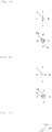
- the handle 33a is configured so that a rotational position thereof is held. For example, when a reference point G of the handle 33a is at the upper side (the position A'), the static magnetic field is directed to the direction A (see Fig. 6A ).
- the static magnetic field can rotate sequentially from the direction A to the directions B, C, and D by 90° each.
- the capsule endoscope 2 is directed to the direction A.
- An image from the capsule endoscope 2 is an image of the direction A.
- the examiner observes the image from the capsule endoscope 2 and wants the capsule endoscope 2 to go straight on, the examiner adjusts the moving speed using the terminal 33a' (see Fig. 1 ) or the like without turning the handle 33a.
- the examiner When the examiner observes the image and wants to change the moving direction of the capsule endoscope 2, the examiner turns the handle 33a leftward or rightward. For example, when the examiner observes the image and wants to change the moving direction of the capsule endoscope 2 rightward by 90°, the examiner turns the handle 33a by 90° rightward. By doing so, the reference point G of the handle 33a is positioned at the right side (the position B'), and the static magnetic field is directed to the direction B (see Fig. 6B ), and the capsule endoscope 2 is directed to the direction B.
- the examiner turns the handle 33a by 90° rightward.
- the reference point G of the handle 33a is positioned at the lower side (the position C'), and the static magnetic field is directed to the direction C (see Fig. 6C ), and the capsule endoscope 2 is directed to the direction C.
- the examiner turns the handle 33a by 90° rightward.
- the reference point G of the handle 33a is positioned at the left side (the position D'), and the static magnetic field is directed to the direction D (see Fig. 6D ), and the capsule endoscope 2 is directed to the direction D.
- the operating unit 33 that uses the handle 33a controls the static magnetic field so as to be directed in the direction corresponding to the reference point G, whereby the moving direction toward the left and right sides of the screen being observed can be controlled by the operation (rotating operation) of the handle 33a.
- the moving direction toward the upper and lower sides of the screen observed may be controlled by changing the moving distance of a movable portion of a slider 33a" as illustrated in Fig. 1 or changing an inclination angle of a shaft 33aa of the handle 33a as illustrated in Figs. 7A to 7C so that the static magnetic field can be controlled to be at an optional angle within a range of -90° and 90° with respect to a horizontal surface.
- the states of the shaft 33aa of the handle 33a can be controlled so as to correspond to a case where the static magnetic field is inclined at -90°, 0°, and 90° with respect to the horizontal surface, respectively.
- another device form may be naturally further used.
- a lever may be used instead of the slider 33a''.
- the reference point G may be invisible.
- the operating unit 33 that uses the joystick 33b may be configured as follows.
- the joystick 33b rotates the direction of the static magnetic field corresponding to a position of a reference point H of a joystick platform 33b'.
- the reference point H is automatically (or manually if necessary) rotated by an angle between upper side (the position A') and a tilt direction of the joystick 33b.
- the static magnetic field is directed to the direction A (see Fig. 8A ).
- the static magnetic field can rotate sequentially from the direction A to the directions B, C, and D by 90° each.
- the capsule endoscope 2 is directed to the direction A.
- An image from the capsule endoscope 2 is an image of the direction A.
- the examiner tilts the joystick 33b toward the upper side (the position A'). By doing so, the capsule endoscope 2 goes straight on at a moving speed corresponding to the tilt inclination angle of the joystick 33b.
- the examiner tilts the joystick 33b in a desired direction. For example, when the examiner observes the image and wants to change the moving direction of the capsule endoscope 2 rightward by 90°, the examiner tilts the joystick 33b rightward. By doing so, the joystick platform 33b' rotates so that the reference point H is at the right side (the position B'), the static magnetic field is directed to the direction B (see Fig. 8B ), and the capsule endoscope 2 is directed to the direction B.
- the examiner when the examiner observes the image and wants to change the moving direction of the capsule endoscope 2 rightward by 90°, the examiner moves back the joystick 33b so as to stand up and then tilts the joystick 33b rightward again.
- the joystick platform 33b' rotates so that the reference point H is at the lower side (the position C'), the static magnetic field is directed to the direction C (see Fig. 8C ), and the capsule endoscope 2 is directed to the direction C.
- the examiner when the examiner observes the image and wants to change the moving direction of the capsule endoscope 2 rightward by 90°, the examiner moves back the joystick 33b so as to stand up and then tilts the joystick 33b rightward again.
- the joystick platform 33b' rotates so that the reference point H is at the left side (the position D'), the static magnetic field is directed to the direction D (see Fig. 8D ), and the capsule endoscope 2 is directed to the direction D.
- the operating unit 33 that uses the joystick 33b controls the static magnetic field so as to be directed in the direction corresponding to the reference point H, whereby the moving direction toward the left and right sides of the screen being observed can be controlled by the operation of the joystick 33b.
- the moving direction toward the upper and lower sides of the screen observed may be controlled by using the slider 33a" or the like described above or by changing the tilt angle of the joystick platform 33b' as illustrated in Figs. 9A to 9C so that the static magnetic field can be controlled to be at an optional angle within a range of -90° and 90° with respect to a horizontal surface.
- FIG. 9A, 9B , and 9C corresponds to a case where the static magnetic field is inclined at -90°, 0°, and 90° with respect to the horizontal surface, respectively.
- Figs. 9A to 9C illustrate a state where the joystick 33b stands up.
- another device form for example, a lever or the like
- the reference point H may be invisible.
- each set of Helmholtz coils is one set of coil pairs made up of two coils provided concentrically and in parallel.
- the shape of the coil of any one or two sets of coil pairs or the three sets of coil pairs of the magnetic field generating portion 31 having three sets of Helmholtz coils may be changed, the size of the coil may be changed, and the distance between two coils that constitute the coil pair may be changed. In this case, a magnetic field is not even (not uniform) but changes depending on a location as will be described later.
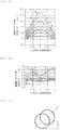
- Figs. 10A to 10C are obtained by simulating the magnetic flux density in the y-axis direction of a magnetic field when one set of coil pairs is disposed so as to generate a magnetic field in the y-axis direction.
- the horizontal axis represents a y-axis coordinate value in which the center represents the middle of two coils, and a unit length is L.
- Figs. 10A , 10B, and 10C illustrate one set of coil pairs so that the distance between two coils is L, 0.5L, and 2L, respectively.
- a curve "a" in the respective drawings illustrates the characteristics a cylindrical coil the circumferential shape of which is a circle having a radius of L (see Fig. 11A ).
- Curves "b,” “c,” “d,” and “e” in the drawings illustrate the characteristics of a coil the circumferential shape of which is a square having each side of 2L, a rectangle having a short side of 2L and a long side of 3L, a rectangle having a short side of 2L and a long side of 4L, and a rectangle having a short side of 2L and a long side of 5L, respectively (see Fig. 11B ).
- Curves “f,” “g, “ “h, “ and “i” in the drawings illustrate the characteristics of a coil the circumferential shape of which is an octagon manufactured by cutting all corners of a quadrangle by a length of 0.5L (see Fig. 11C ).
- the octagons corresponding to the curves "f,” “g,” “h,” and “i” are manufactured from a square having each side of 2L, a rectangle having a short side of 2L and a long side of 3L, a rectangle having a short side of 2L and a long side of 4L, and a rectangle having a short side of 2L and a long side of 5L, respectively.
- the curve "a” in Fig. 10A illustrates the characteristics of one set of Helmholtz coils.
- Figs. 10A to 10C when the shape of the coil is modified to a polygonal shape such as a quadrangle or an octagon and the distance between two coils is made different from the distance (the distance between two coils that constitute the Helmholtz coils) of the Helmholtz coils, the magnetic field changes depending on a location and the characteristics of the coils deviate from the characteristics of the Helmholtz coils.
- Fig. 10A to 10C when the shape of the coil is modified to a polygonal shape such as a quadrangle or an octagon and the distance between two coils is made different from the distance (the distance between two coils that constitute the Helmholtz coils) of the Helmholtz coils, the magnetic field changes depending on a location and the characteristics of the coils deviate from the characteristics of the Helmholtz coils.
- the dependence on location of the magnetic field decreases if the size in one direction (long-side direction) of a polygon is larger than the size in the other direction (short-side direction) so that the size in one direction (long-side direction) of a polygon approaches the distance between the two coils.
- a polygon in which the size in one direction is larger than the size in the other direction orthogonal to the direction is referred to as an oblong polygon.
- a magnetic field generating portion 36 includes one set of Helmholtz coils and two sets of coil pairs obtained by modifying the structure (the shape and size of coils and the distance between two coils) of the Helmholtz coils so as to surround the capsule endoscope 2 from three orthogonal directions.
- one set of Helmholtz coils is one set of z-axis Helmholtz coils 36z and 36z' that generates a magnetic field in the z-axis direction.
- the other two sets of coil pairs are one set of x-axis coil pairs 36x and 36x' that generates a magnetic field in the x-axis direction and one set of y-axis coil pairs 36y and 36y' that generates a magnetic field in the y-axis direction.
- the magnetic field generating portion 36 enables to decrease an overall size thereof although a change in the magnetic field depending on the location in the x-axis direction and the y-axis direction increases as compared to the magnetic field generating portion 31 having three sets of Helmholtz coils, because it is not necessary in the magnetic field generating portion 36 to arrange a plurality of orthogonal Helmholtz coils so as not to overlap. It is a little difficult to control the magnetic field generating portion 36 because the magnetic field in the x-axis direction and the y-axis direction is not uniform though the magnetic field in the z-axis direction is uniform. However, it is possible to generate the static magnetic field and the alternating magnetic field in a manner similarly to the magnetic field generating portion 31 described above and to control the moving direction and the moving speed of the capsule endoscope 2.
- the coils 36x, 36x', 36y, and 36y' that constitute the coil pairs may have a polygonal circumferential shape or an elliptical or circular circumferential shape that is more similar to the shape of the Helmholtz coil.
- the distance between the two coils that constitute the coil pair is large, if the coils 36x, 36x', 36y, and 36y' have such an oblong polygonal or elliptical circumferential shape that the size in the y-axis direction or the x-axis direction is larger than the size in the z-axis direction, it is possible to suppress a change in the magnetic field depending on location in the x-axis direction and the y-axis direction while decreasing the size in the z-axis direction.
- the present invention is not limited to the magnetic field generating portion 36 but can be modified in various ways.
- the shape of the coils of any one or two sets of coil pairs or the three sets of coil pairs of the magnetic field generating portion 31 having three sets of Helmholtz coils may be changed and the size of the coils and the distance between two coils may be changed.
- the coils that constitute each of the three sets of coil pairs each have a circumferential shape that is selected from a polygonal shape, an elliptical shape, and a circular shape.
- the coil has a polygonal circumferential shape
- a quadrangular circumferential shape or a polygonal circumferential shape having more corners than a quadrangle which is preferred from the perspective of the above-described characteristics can be used.
- the coils that constitute any one or two sets of the three sets of coil pairs or the three sets of coil pairs may each have a circumferential shape that is an oblong polygonal shape or an elliptical shape which is preferred from the perspective of the above-described characteristics.
- a magnetic field generating portion 37 that includes one set of Helmholtz coils and two sets of electromagnets so as to surround the capsule endoscope 2 from three orthogonal directions may be used.
- the magnetic field generating portion 37 includes one set of x-axis electromagnets 37x and 37x' that generates a magnetic field in the x-axis direction, one set of y-axis Helmholtz coils 37y and 37y' that generates a magnetic field in the y-axis direction, and one set of z-axis electromagnets 37z and 37z' that generates a magnetic field in the z-axis direction.
- the subject may lie or stand up in parallel to the y-axis direction.
- the magnetic field generating portion 37 including one set of Helmholtz coils and two sets of electromagnets is heavy and generates a magnetic field that is uneven (not uniform), since the size of the electromagnet is small, and the radius and the gap of one set of Helmholtz coils can be freely decreased, it is possible to decrease the overall size. It becomes a little difficult to control the magnetic field generating portion 37 because the magnetic field in the x-axis direction and the z-axis direction is not uniform. However, it is possible to generate the static magnetic field and the alternating magnetic field and to control the moving direction and the moving speed of the capsule endoscope 2.
- the present invention can be changed in design in various ways within the scope described in the claims without being limited to those described in the embodiment.
- the structure and the shape of the endoscope main body 2a of the capsule endoscope 2 may come in various types.
- the shapes of the handle 33a and the joystick 33b of the operating unit 33 of the capsule controller 3 are not limited to particular shapes, and for example, the handle 33a may have a dial shape, a knob shape, or a shape of a joystick that does not stand in addition to the shapes illustrated in Figs. 6A to 6D .
- the operating unit 33 of the capsule controller 3 may use a keyboard, a mouse, a touch panel, and the like of a PC instead of the handle 33a, the joystick 33b (and the joystick platform 33b'), and the like so that the same signal as the control signal output from the operating unit 33 according to the operation of the handle 33a, the joystick 33b (and the joystick platform 33b'), and the like is output according to software.
Landscapes
- Health & Medical Sciences (AREA)
- Life Sciences & Earth Sciences (AREA)
- Surgery (AREA)
- Nuclear Medicine, Radiotherapy & Molecular Imaging (AREA)
- Biomedical Technology (AREA)
- Optics & Photonics (AREA)
- Pathology (AREA)
- Radiology & Medical Imaging (AREA)
- Biophysics (AREA)
- Engineering & Computer Science (AREA)
- Physics & Mathematics (AREA)
- Heart & Thoracic Surgery (AREA)
- Medical Informatics (AREA)
- Molecular Biology (AREA)
- Animal Behavior & Ethology (AREA)
- General Health & Medical Sciences (AREA)
- Public Health (AREA)
- Veterinary Medicine (AREA)
- Endoscopes (AREA)
Description
- The present invention relates to a medical device including a capsule endoscope capable of being self-propelled through the inside of a body and a capsule controller that controls self-propulsion of the capsule endoscope from the outside of the body.
- In recent years, a medical device that examines the inside of a body using a capsule endoscope capable of being self-propelled through the inside of the body is known. The capsule endoscope in this medical device generally imposes less burden on a subject because, unlike conventional endoscopes, it does not require a tube that passes through the gullet or the like for operating the endoscope. When a subject swallows the capsule endoscope, the capsule endoscope moves through the inside of the body according to a peristaltic movement of the stomach or the intestines while capturing images of the surroundings with an internal camera, and the captured images are transmitted to a capsule controller that controls the self-propulsion of the capsule endoscope from the outside of the body and are stored in a storage medium. Thereafter, the capsule endoscope is discharged outside from the anus.
- Such a self-propelled capsule endoscope can move to a destination to be examined by itself as well as moving passively according to the peristaltic movement. For example,
Patent Document 1 discloses a capsule endoscope in which a magnet having a magnetization direction in a direction orthogonal to an axial direction (longitudinal direction) is mounted and a propulsive power generating portion having a spiral structure is provided at the rear end in the axial direction. This capsule endoscope is configured such that the magnet rotates in response to a rotational magnetic field generated by a capsule controller disposed at the outside of the body, and the propulsive power generating portion rotates with rotation of the magnet, whereby propulsive power in the axial direction is generated. -
Patent Document 2 discloses a capsule endoscope in which a magnet having a magnetization direction in an axial direction (longitudinal direction) is mounted and a fin portion is provided at the rear end in the axial direction. This capsule endoscope is configured such that the magnet vibrates in response to an alternating magnetic field generated by a capsule controller disposed at the outside, and the fin portion vibrates by bending with the vibration of the magnet to push surrounding liquid backward, whereby propulsive power in the axial direction is generated. InPatent Document 2, the position of an electromagnet that generates a one-directional alternating magnetic field is controlled by a guide rail and a lift so that the capsule endoscope is moved to a destination to be examined. - Since the attitude of the capsule endoscope of
Patent Document 2 is stable so that the fin portion bends in the direction of the alternating magnetic field, the capsule endoscope can obtain stable images and perform examinations easily as compared to the capsule endoscope ofPatent Document 1 in which images captured by the internal camera are likely to rotate or be inclined unstably with rotation of the propulsive power generating portion. Moreover, since the capsule endoscope ofPatent Document 2 can move a large amount of liquid backward with strong force by means of the fin portion, it is possible to easily increase the propulsive power with a small size as compared to the capsule endoscope ofPatent Document 1 in which the propulsive power is obtained by rotation of the propulsive power generating portion, and to reduce the possibility that the body walls (wall surfaces inside the body) are damaged with friction. -
JP 2006/062071 A -
- Patent Document 1: Japanese Patent Application Publication No.
2001-179700 - Patent Document 2: Japanese Patent Application Publication No.
2008-279019 - Such a capsule endoscope that is propelled by vibration of the fin portion as disclosed in
Patent Document 2 has several advantages. In the meantime, since the path along which the capsule endoscope advances through the inside of the body comes in various types including a relatively wide area like the stomach and a crooked areas like the intestines, it is important to control the moving direction of the capsule endoscope. The capsule endoscope propelled by vibration of the fin portion can change the moving direction thereof by applying a bias magnetic field in parallel to the alternating magnetic field. - However, in the method of applying the bias magnetic field in parallel to the alternating magnetic field, it is not always easy to accurately move the capsule endoscope to a destination to be examined since the capsule endoscope gradually changes the moving direction thereof while moving.
- The present invention has been made in view of the foregoing, and an object thereof is to provide a medical device including a self-propelled capsule endoscope that is propelled through the inside of a body by vibration of a fin portion and a capsule controller that controls self-propulsion of the capsule endoscope from the outside of the body, the medical device being capable of precisely controlling the moving direction of the capsule endoscope easily.
- In order to attain the object, according to a preferred embodiment of the present invention, there is provided a medical device according to
claim 1. - Preferably, the capsule controller generates the static magnetic field and the alternating magnetic field by means of a magnetic field generating portion that includes three sets of Helmholtz coils. Alternatively, the capsule controller generates the static magnetic field and the alternating magnetic field by means of a magnetic field generating portion that includes three sets of coil pairs, and coils that constitute each of the three sets of coil pairs each have a circumferential shape that is selected from a polygonal shape, an elliptical shape, and a circular shape. In this case, it is preferable that coils that constitute any one or two sets of the three sets of coil pairs or the three sets of coil pairs each have a circumferential shape that is an oblong polygonal shape or an elliptical shape. Alternatively, the capsule controller generates the static magnetic field and the alternating magnetic field by means of a magnetic field generating portion that includes one set of Helmholtz coils and two sets of electromagnets.
- More preferably, the capsule controller is configured to be able to change an amplitude and/or a frequency of the alternating magnetic field and/or to change a magnitude of the static magnetic field. In this case, it is preferable that the amplitude and/or the frequency of the alternating magnetic field and/or the magnitude of the static magnetic field corresponds to a turn angle of a terminal, a tilt angle of a joystick, a moving distance of a lever, or a depression amount of an accelerator.
- Further preferably, the direction of the static magnetic field is controlled by an operating unit that uses a handle whose rotational position can be held, and corresponds to a direction of a reference point of the handle. In this case, an inclination angle of the static magnetic field in relation to a horizontal surface is controlled by changing an inclination angle of a shaft of the handle or by changing a moving distance of a movable portion of a slider or a lever. Alternatively, the direction of the static magnetic field is controlled by an operating unit that uses a joystick, and a reference point of a joystick platform is rotated by an angle corresponding to a tilt direction of the joystick, thus the direction of the static magnetic field corresponds to the direction of the reference point. In this case, an inclination angle of the static magnetic field in relation to a horizontal surface is controlled by changing a tilt angle of the joystick platform or by changing a moving distance of a movable portion of a slider or a lever.
- According to the medical device of the present invention, since the moving direction of the capsule endoscope in the inside of the body is controlled according to the static magnetic field, and independently from this, the propulsive power is controlled by the alternating magnetic field orthogonal to the static magnetic field, the moving direction and the moving speed of the capsule endoscope can be easily controlled precisely.
-
-
Fig. 1 is a schematic diagram illustrating a configuration of a medical device according to an embodiment of the present invention; -
Figs. 2A and 2B are external views illustrating a schematic configuration of a capsule endoscope of the medical device, in whichFig. 2A is a side view andFig. 2B is a plan view; -
Fig. 3 is a plan view schematically illustrating an example of propulsion of the capsule endoscope of the medical device; -
Fig. 4 is a schematic pictorial diagram illustrating a configuration of a magnetic field generating portion of the medical device; -
Fig. 5 is a waveform diagram illustrating examples of a magnetic field generated by the magnetic field generating portion of the medical device; -
Figs. 6A to 6D are schematic diagrams illustrating examples of the relationship between the state of a handle of an operating unit of the medical device and the state of the capsule endoscope; -
Figs. 7A to 7C are schematic diagrams illustrating examples of inclination of the handle of the operating unit of the medical device; -
Figs. 8A to 8D are schematic diagrams illustrating examples of the relationship between the state of a joystick of another operating unit of the medical device and the state of the capsule endoscope; -
Figs. 9A to 9C are schematic diagrams illustrating examples of inclination of a joystick platform of the operating unit of the medical device; -
Figs. 10A to 10C are diagrams illustrating the characteristics of one set of coil pairs obtained for use in a modification of the magnetic field generating portion of the medical device; -
Figs. 11A to 11C are schematic pictorial diagrams illustrating one set of coil pairs used when obtaining the characteristics ofFigs. 10A to 10C ; -
Fig. 12 is a schematic pictorial diagram illustrating a configuration of a modification of the magnetic field generating portion of the medical device; and -
Fig. 13 is a schematic pictorial diagram illustrating a configuration of another modification of the magnetic field generating portion of the medical device. - Hereinafter, preferred embodiments of the present invention will be described with reference to the drawings. A
medical device 1 according to an embodiment of the present invention performs internal examinations or the like of a subject, and as illustrated inFig. 1 , includes acapsule endoscope 2 that can be self-propelled at the inside of the body of the subject and acapsule controller 3 that controls self-propulsion of thecapsule endoscope 2 from the outside of the body. The subject is positioned so that a body portion thereof is located inside a predetermined range defined by a magneticfield generating portion 31 described later of thecapsule controller 3 and is examined after swallowing thecapsule endoscope 2 from the mouth. Thecapsule endoscope 2 may be inserted from the anus. - The
capsule endoscope 2 is generally an approximately cylindrical endoscope that moves in an axial direction (longitudinal direction), and as illustrated inFigs. 2A and 2B , includes an endoscopemain body 2a in which acamera 22 or the like is mounted and afin portion 2b in which amagnet 21 having a magnetization direction in the axial direction is mounted. Thefin portion 2b is provided at the rear end in the axial direction of the endoscopemain body 2a, and specifically, a front end of thefin portion 2b is fixed to the rear end of the endoscopemain body 2a directly or with a cap-shaped member or the like interposed. In the present embodiment, thecapsule endoscope 2 has such a size that a length in the axial direction is approximately 4.5 cm, for example, and a diameter is approximately 1 cm. - The structure of the endoscope
main body 2a is not the point of the present invention, and an existing one that is used in the conventional capsule endoscope can be used. As illustrated inFigs. 2A and 2B , such an endoscopemain body 2a generally includes, in addition to the above-describedcamera 22, apower supply unit 23 that supplies electric power to respective units of thecapsule endoscope 2, anillumination unit 24 that illuminates the outside in order to allow thecamera 22 to capture images, awireless communication unit 25 that wirelessly transmits the images captured by thecamera 22 to thecapsule controller 3, and the like. A front part (the left part inFigs. 2A and 2B ) of the endoscopemain body 2a is transparent so that light can pass through the front part. Thecamera 22 is constituted of a CCD or the like, thepower supply unit 23 is constituted of a battery or the like, and the illuminatingunit 24 is constituted of an LED or the like. Thewireless communication unit 25 may be configured to wirelessly receive a control signal from thecapsule controller 3 to control thecamera 22, the illuminatingunit 24, and the like. - The
magnet 21 of thefin portion 2b is a rod-shaped magnet, and as described above, has the same magnetization direction as the axial direction of thecapsule endoscope 2. Themagnet 21 is mounted in an elastic member such as a silicon resin. Themagnet 21 receives a static magnetic field and an alternating magnetic field orthogonal to the static magnetic field, generated by a magneticfield generating portion 31 described later of thecapsule controller 3. Upon receiving the static magnetic field, themagnet 21 rotates so that it is parallel to the direction of the static magnetic field. Thecapsule endoscope 2 rotates with the rotation of themagnet 21. Moreover, themagnet 21 vibrates in response to the alternating magnetic field. Accordingly, as illustrated inFig. 3 , thefin portion 2b vibrates by bending to push surrounding liquid backward whereby propulsive power in the axial direction is generated. - Since the front end of the
fin portion 2b is fixed to the endoscopemain body 2a and the rear end is open, when themagnet 21 vibrates, the rear end (the S-pole side inFigs. 2A and 2B ) of themagnet 21 moves greatly according to the alternating magnetic field and the front end (the N-pole side inFigs. 2A and 2B ) vibrates with a very small amplitude (seeFig. 3 ). - The
fin portion 2b has a wide side surface such that it bends like the fin of a fish to efficiently push liquid backward. The shape of the side surface is appropriately selected. For example, a posterior part of the side surface may have a trapezoidal shape as illustrated inFig. 2A , or thefin portion 2b may have a generally round shape or an oblong shape. Moreover, the thickness (a width of a surface orthogonal to the wide side surface) of thefin portion 2b may be set such that the anterior part thereof is thin and the posterior part thereof is thinner as illustrated inFig. 2B . Or, theentire fin portion 2b may have the same thickness. When an alternating magnetic field is orthogonally incident on the wide side surface of thefin portion 2b so that thefin portion 2b bends, an attitude of thecapsule endoscope 2 is stabilized. - Next, the
capsule controller 3 will be described. As illustrated inFigs. 1 and4 , thecapsule controller 3 includes the magneticfield generating portion 31 that surrounds thecapsule endoscope 2 from three orthogonal directions. The magneticfield generating portion 31 consists of three sets of Helmholtz coils composed of one set of x-axis Helmholtz coils 31x and 31x' for generating a magnetic field in an x-axis direction (left-right direction inFig. 1 ), one set of y-axis Helmholtz coils 31y and 31y' for generating a magnetic field in a y-axis direction (up-down direction inFig. 1 ), and one set of z-axis Helmholtz coils 31z and 31z' for generating a magnetic field in a z-axis direction (direction vertical to the drawing sheet inFig. 1 ). InFig. 1 , the subject lies or stands up in parallel to the y-axis direction. Moreover, inFig. 1 , one z-axis Helmholtz coil 31z' is located behind the other z-axis Helmholtz coil 31z. - The magnetic
field generating portion 31 is configured to generate a static magnetic field that does not change over time and generate an alternating magnetic field that changes over time with a predetermined frequency and amplitude according to a control current from the magneticfield control unit 32 and to generate a combination of a static magnetic field and an alternating magnetic field. The static magnetic field and the alternating magnetic field can be directed in any 3-dimensional direction. Specifically, based on a control signal from the operatingunit 33 described later, an x-axis magneticfield control unit 32x of the magneticfield control unit 32 supplies such a current that generates an x-axis directional magnetic field component to the x-axis Helmholtz coils 31x and 31x', a y-axis magneticfield control unit 32y supplies such a current that generates a y-axis directional magnetic field component to the y-axis Helmholtz coils 31y and 31y', and a z-axis magneticfield control unit 32z supplies such a current that generates a z-axis directional magnetic field component to the z-axis Helmholtz coils 31z and 31z'. - The x-axis Helmholtz coils 31x and 31x' have such a structure that cylindrical coils around which a plurality of wires is wound are provided concentrically and in parallel so as to be separated by the same distance R' as a radius R of the coil so that a uniform magnetic field is generated at a central axis. The x-axis Helmholtz coils 31x and 31x' are configured to be able to generate a uniform magnetic field in the x-axis direction at the central axis by supplying the same directional current to the x-axis Helmholtz coils 31x and 31x'. Such an iron core as used in an electromagnet is not used for generating a magnetic field. In practice, although a small variation generally occurs due to the width, the thickness, and the installing conditions or the like of the coils around which a plurality of wires is wound, it is possible to generate a substantially uniform magnetic field in the x-axis direction in a space near the central axis. For example, an allowable variation of the average distance R' in relation to the average radius R of the coil may be controlled to be within 10% or 20%. The fact that a substantially uniform magnetic field is generated in a space near the central axis is different from that of an electromagnet in which the magnetic field changes greatly depending on the position in the central axis direction. The same is true for the y-axis Helmholtz coils 31y and 31y' and the z-axis Helmholtz coils 31z and 31z'. Thus, in a certain range near the center of the magnetic
field generating portion 31, the combined magnetic field is substantially uniform in any direction, and basically, thecapsule endoscope 2 is controlled by thecapsule controller 3 in or near this range. In general, it is necessary to arrange the x-axis Helmholtz coils 31x and 31x', the y-axis Helmholtz coils 31y and 31y', and the z-axis Helmholtz coils 31z and 31z' sequentially on the outer side while increasing the radii and gaps (distances) thereof. Moreover, the radii and gaps thereof are not particularly limited, and the order of the radii and gaps thereof is not limited. - The static magnetic field is used for controlling a moving direction of the
capsule endoscope 2. The magneticfield control unit 32 supplies a direct current to the three sets of Helmholtz coils of the magneticfield generating portion 31 to generate a static magnetic field so that the direction of the combined static magnetic field corresponds to a target moving direction. By doing so, themagnet 21 of thecapsule endoscope 2 rotates quickly so as to be aligned in parallel to the direction of the static magnetic field, and thecapsule endoscope 2 rotates with the rotation so as to be aligned in a direction identical to the target moving direction. - Moreover, the alternating magnetic field is used for propelling the
capsule endoscope 2. The magneticfield control unit 32 supplies an alternating current to the three sets of Helmholtz coils of the magneticfield generating portion 31 to generate alternating magnetic field components and controls the alternating magnetic field components so that the direction of the combined alternating magnetic field is orthogonal to the static magnetic field. By doing so, themagnet 21 of thecapsule endoscope 2 vibrates in a direction approximately orthogonal to the target moving direction, thefin portion 2b vibrates in a direction approximately orthogonal to the target moving direction with the vibration, and as a result, thecapsule endoscope 2 is self-propelled in the target moving direction. - Here, in a region near the center of the magnetic
field generating portion 31, since the static magnetic field acting on thecapsule endoscope 2 is substantially uniform, thecapsule endoscope 2 just rotates so that the axis of thecapsule endoscope 2 is parallel to the direction of the static magnetic field and is rarely attracted in a specific direction. Thus, it is easy to control the moving direction. Moreover, in a region near the center of the magneticfield generating portion 31, since the dependence on position of the magnitude of the alternating magnetic field acting on thecapsule endoscope 2 is very small, it is easy to control the moving speed. - Although the point in time when the static magnetic field and the alternating magnetic field are generated is not particularly limited, since the moving direction is generally quickly determined by the static magnetic field, the static magnetic field is generated simultaneously with the alternating magnetic field. The static magnetic field and the alternating magnetic field are generated simultaneously and combined. For example, if the moving direction is 45°, 45°, and 90° with respect to the x, y, and z axes, respectively, the x- and y-axis directional magnetic field components may be static magnetic field components of the same values and the z-axis directional magnetic field may be an alternating magnetic field as illustrated in
Fig. 5 . - By changing the amplitude and the frequency of the alternating magnetic field, the moving speed can be decreased according to the control signal from the operating
unit 33 described later so that the details of the images from thecapsule endoscope 2 can be observed, or the propulsive power can be increased according to the control signal so that thecapsule endoscope 2 can easily pass through an area where it is difficult for thecapsule endoscope 2 to pass. Moreover, by changing the magnitude of the static magnetic field, the magnitude of force directed to the target moving direction can be controlled according to the control signal from the operatingunit 33 described later so that thecapsule endoscope 2 can be easily directed in an area where it is usually difficult for thecapsule endoscope 2 to be directed to the target moving direction due to an obstacle or the like. In order to change the amplitude and the frequency of the alternating magnetic field, the amplitude and frequency may be adjusted so as to correspond to the turn angle of a terminal 33a' (seeFig. 1 ) described later or the tilt angle of ajoystick 33b described later. Or, a manually operated lever (not illustrated) or a foot accelerator (not illustrated) may be prepared so that the amplitude and frequency may be adjusted so as to correspond to a moving distance of the lever or a depression amount of the accelerator. Further, in order to change the magnitude of the static magnetic field, the magnitude of the static magnetic field may be changed whenever the amplitude and the frequency of the alternating magnetic field are changed, or may be changed independently by the terminal 33a', the lever, or the like. - Moreover, when the alternating magnetic field starts to be generated, it possibly occurs that the angle between the vibrating direction of the
fin portion 2b and the direction of the alternating magnetic field is close to orthogonal so that it is difficult for thefin portion 2b to vibrate. In this case, the direction of the alternating magnetic field may be changed within a range where the direction is orthogonal to the static magnetic field according to the control signal from the operatingunit 33. - In this manner, since the moving direction and the propulsive power (moving speed) of the
capsule endoscope 2 can be controlled independently, it is easy to accurately move thecapsule endoscope 2 to a destination to be examined. - Moreover, the
capsule controller 3 includes the operatingunit 33 that is operated by an examiner as described above. The operatingunit 33 controls the moving direction or the like of thecapsule endoscope 2 using an operating device such as thehandle 33a as illustrated inFigs. 1 and6A to 6D or thejoystick 33b as illustrated inFigs. 8A to 8D . The direction of the static magnetic field is controlled based on a signal output by the operatingunit 33. In addition to this, a device that controls the amplitude, frequency, or direction of the alternating magnetic field, a device that controls the magnitude of the static magnetic field, and the like may be provided. Moreover, in the present embodiment, a communicatingunit 34 receives in-vivo images transmitted from thecapsule endoscope 2 and the images are displayed on adisplay device 35. The examiner can operate the operating device such as thehandle 33a or thejoystick 33b while observing the images. - The operating
unit 33 that uses thehandle 33a may be configured as follows. Thehandle 33a is configured so that a rotational position thereof is held. For example, when a reference point G of thehandle 33a is at the upper side (the position A'), the static magnetic field is directed to the direction A (seeFig. 6A ). The static magnetic field can rotate sequentially from the direction A to the directions B, C, and D by 90° each. When the static magnetic field is directed to the direction A, thecapsule endoscope 2 is directed to the direction A. An image from thecapsule endoscope 2 is an image of the direction A. When the examiner observes the image from thecapsule endoscope 2 and wants thecapsule endoscope 2 to go straight on, the examiner adjusts the moving speed using the terminal 33a' (seeFig. 1 ) or the like without turning thehandle 33a. - When the examiner observes the image and wants to change the moving direction of the
capsule endoscope 2, the examiner turns thehandle 33a leftward or rightward. For example, when the examiner observes the image and wants to change the moving direction of thecapsule endoscope 2 rightward by 90°, the examiner turns thehandle 33a by 90° rightward. By doing so, the reference point G of thehandle 33a is positioned at the right side (the position B'), and the static magnetic field is directed to the direction B (seeFig. 6B ), and thecapsule endoscope 2 is directed to the direction B. Similarly, in a state where thecapsule endoscope 2 is directed to the position B, when the examiner observes the image and wants to change the moving direction of thecapsule endoscope 2 rightward by 90°, the examiner turns thehandle 33a by 90° rightward. By doing so, the reference point G of thehandle 33a is positioned at the lower side (the position C'), and the static magnetic field is directed to the direction C (seeFig. 6C ), and thecapsule endoscope 2 is directed to the direction C. Similarly, in a state where thecapsule endoscope 2 is directed to the position C, when the examiner observes the image and wants to change the moving direction of thecapsule endoscope 2 rightward by 90°, the examiner turns thehandle 33a by 90° rightward. By doing so, the reference point G of thehandle 33a is positioned at the left side (the position D'), and the static magnetic field is directed to the direction D (seeFig. 6D ), and thecapsule endoscope 2 is directed to the direction D. - In this manner, the operating
unit 33 that uses thehandle 33a controls the static magnetic field so as to be directed in the direction corresponding to the reference point G, whereby the moving direction toward the left and right sides of the screen being observed can be controlled by the operation (rotating operation) of thehandle 33a. The moving direction toward the upper and lower sides of the screen observed may be controlled by changing the moving distance of a movable portion of aslider 33a" as illustrated inFig. 1 or changing an inclination angle of a shaft 33aa of thehandle 33a as illustrated inFigs. 7A to 7C so that the static magnetic field can be controlled to be at an optional angle within a range of -90° and 90° with respect to a horizontal surface. For example, the states of the shaft 33aa of thehandle 33a, as shown inFigs. 7A ,7B, and 7C , can be controlled so as to correspond to a case where the static magnetic field is inclined at -90°, 0°, and 90° with respect to the horizontal surface, respectively. In place of the terminal 33a' or theslider 33a", another device form may be naturally further used. For example, a lever may be used instead of theslider 33a''. Moreover, the reference point G may be invisible. - The operating
unit 33 that uses thejoystick 33b may be configured as follows. Thejoystick 33b rotates the direction of the static magnetic field corresponding to a position of a reference point H of ajoystick platform 33b'. The reference point H is automatically (or manually if necessary) rotated by an angle between upper side (the position A') and a tilt direction of thejoystick 33b. For example, when the reference point H of thejoystick platform 33b' is at the upper side (the position A'), the static magnetic field is directed to the direction A (seeFig. 8A ). The static magnetic field can rotate sequentially from the direction A to the directions B, C, and D by 90° each. When the static magnetic field is directed to the direction A, thecapsule endoscope 2 is directed to the direction A. An image from thecapsule endoscope 2 is an image of the direction A. When the examiner observes the image from thecapsule endoscope 2 and wants thecapsule endoscope 2 to go straight on, the examiner tilts thejoystick 33b toward the upper side (the position A'). By doing so, thecapsule endoscope 2 goes straight on at a moving speed corresponding to the tilt inclination angle of thejoystick 33b. - When the examiner observes the image and wants to change the moving direction of the
capsule endoscope 2, the examiner tilts thejoystick 33b in a desired direction. For example, when the examiner observes the image and wants to change the moving direction of thecapsule endoscope 2 rightward by 90°, the examiner tilts thejoystick 33b rightward. By doing so, thejoystick platform 33b' rotates so that the reference point H is at the right side (the position B'), the static magnetic field is directed to the direction B (seeFig. 8B ), and thecapsule endoscope 2 is directed to the direction B. Similarly, in a state where thecapsule endoscope 2 is directed to the direction B, when the examiner observes the image and wants to change the moving direction of thecapsule endoscope 2 rightward by 90°, the examiner moves back thejoystick 33b so as to stand up and then tilts thejoystick 33b rightward again. By doing so, thejoystick platform 33b' rotates so that the reference point H is at the lower side (the position C'), the static magnetic field is directed to the direction C (seeFig. 8C ), and thecapsule endoscope 2 is directed to the direction C. Similarly, in a state where thecapsule endoscope 2 is directed to the direction C, when the examiner observes the image and wants to change the moving direction of thecapsule endoscope 2 rightward by 90°, the examiner moves back thejoystick 33b so as to stand up and then tilts thejoystick 33b rightward again. By doing so, thejoystick platform 33b' rotates so that the reference point H is at the left side (the position D'), the static magnetic field is directed to the direction D (seeFig. 8D ), and thecapsule endoscope 2 is directed to the direction D. - In this manner, the operating
unit 33 that uses thejoystick 33b controls the static magnetic field so as to be directed in the direction corresponding to the reference point H, whereby the moving direction toward the left and right sides of the screen being observed can be controlled by the operation of thejoystick 33b. The moving direction toward the upper and lower sides of the screen observed may be controlled by using theslider 33a" or the like described above or by changing the tilt angle of thejoystick platform 33b' as illustrated inFigs. 9A to 9C so that the static magnetic field can be controlled to be at an optional angle within a range of -90° and 90° with respect to a horizontal surface. For example, the state of thejoystick platform 33b' inFigs. 9A, 9B , and9C corresponds to a case where the static magnetic field is inclined at -90°, 0°, and 90° with respect to the horizontal surface, respectively. Note thatFigs. 9A to 9C illustrate a state where thejoystick 33b stands up. Moreover, in place of theslider 33a'', another device form (for example, a lever or the like) may be naturally further used. Moreover, the reference point H may be invisible. - An embodiment in which the
capsule controller 3 is configured using the magneticfield generating portion 31 has been described. Since the use of the magneticfield generating portion 31 having three sets of Helmholtz coils enables a magnetic field to become substantially uniform as described above, it becomes easy to control the moving direction and the propulsive power (moving speed). Each set of Helmholtz coils is one set of coil pairs made up of two coils provided concentrically and in parallel. When miniaturization or the like is prioritized, the shape of the coil of any one or two sets of coil pairs or the three sets of coil pairs of the magneticfield generating portion 31 having three sets of Helmholtz coils may be changed, the size of the coil may be changed, and the distance between two coils that constitute the coil pair may be changed. In this case, a magnetic field is not even (not uniform) but changes depending on a location as will be described later. - The characteristics illustrated in
Figs. 10A to 10C are obtained by simulating the magnetic flux density in the y-axis direction of a magnetic field when one set of coil pairs is disposed so as to generate a magnetic field in the y-axis direction. The horizontal axis represents a y-axis coordinate value in which the center represents the middle of two coils, and a unit length is L.Figs. 10A ,10B, and 10C illustrate one set of coil pairs so that the distance between two coils is L, 0.5L, and 2L, respectively. A curve "a" in the respective drawings illustrates the characteristics a cylindrical coil the circumferential shape of which is a circle having a radius of L (seeFig. 11A ). Curves "b," "c," "d," and "e" in the drawings illustrate the characteristics of a coil the circumferential shape of which is a square having each side of 2L, a rectangle having a short side of 2L and a long side of 3L, a rectangle having a short side of 2L and a long side of 4L, and a rectangle having a short side of 2L and a long side of 5L, respectively (seeFig. 11B ). Curves "f," "g, " "h, " and "i" in the drawings illustrate the characteristics of a coil the circumferential shape of which is an octagon manufactured by cutting all corners of a quadrangle by a length of 0.5L (seeFig. 11C ). The octagons corresponding to the curves "f," "g," "h," and "i" are manufactured from a square having each side of 2L, a rectangle having a short side of 2L and a long side of 3L, a rectangle having a short side of 2L and a long side of 4L, and a rectangle having a short side of 2L and a long side of 5L, respectively. Note that the curve "a" inFig. 10A illustrates the characteristics of one set of Helmholtz coils. - It can be understood from
Figs. 10A to 10C that, when the shape of the coil is modified to a polygonal shape such as a quadrangle or an octagon and the distance between two coils is made different from the distance (the distance between two coils that constitute the Helmholtz coils) of the Helmholtz coils, the magnetic field changes depending on a location and the characteristics of the coils deviate from the characteristics of the Helmholtz coils. On the other hand, it can be understood fromFig. 10A that, when the distance between two coils is the same as the distance of the Helmholtz coils, the closer the size in one direction (the long-side direction) of a coil to the size in the other direction (the short-side direction), and the more the number of corners of the polygonal shape of a coil lager than a quadrangle (that is, the closer the shape to a circle or an ellipse), the more the characteristics of the coils similar to the characteristics of the Helmholtz coil. Moreover, it can be understood fromFigs. 10A to 10C that the more the number of corners of the polygonal shape of a coil lager than a quadrangle (that is, the closer the shape to a circle or an ellipse), the larger the magnetic flux density is obtained. Furthermore, the curves "g," "h," and "i" exhibit smaller dependence on location of the magnetic field than the curve "f" inFig 10c . It can be understood that, when the distance between two coils is larger than the distance of the Helmholtz coil, the dependence on location of the magnetic field decreases if the size in one direction (long-side direction) of a polygon is larger than the size in the other direction (short-side direction) so that the size in one direction (long-side direction) of a polygon approaches the distance between the two coils. In the present application, a polygon in which the size in one direction is larger than the size in the other direction orthogonal to the direction is referred to as an oblong polygon. - A magnetic
field generating portion 36 includes one set of Helmholtz coils and two sets of coil pairs obtained by modifying the structure (the shape and size of coils and the distance between two coils) of the Helmholtz coils so as to surround thecapsule endoscope 2 from three orthogonal directions. As illustrated inFig. 12 , in this example, one set of Helmholtz coils is one set of z-axis Helmholtz coils 36z and 36z' that generates a magnetic field in the z-axis direction. Moreover, the other two sets of coil pairs are one set of x-axis coil pairs 36x and 36x' that generates a magnetic field in the x-axis direction and one set of y-axis coil pairs 36y and 36y' that generates a magnetic field in the y-axis direction. - The magnetic
field generating portion 36 enables to decrease an overall size thereof although a change in the magnetic field depending on the location in the x-axis direction and the y-axis direction increases as compared to the magneticfield generating portion 31 having three sets of Helmholtz coils, because it is not necessary in the magneticfield generating portion 36 to arrange a plurality of orthogonal Helmholtz coils so as not to overlap. It is a little difficult to control the magneticfield generating portion 36 because the magnetic field in the x-axis direction and the y-axis direction is not uniform though the magnetic field in the z-axis direction is uniform. However, it is possible to generate the static magnetic field and the alternating magnetic field in a manner similarly to the magneticfield generating portion 31 described above and to control the moving direction and the moving speed of thecapsule endoscope 2. - The
coils coils - The present invention is not limited to the magnetic
field generating portion 36 but can be modified in various ways. For example, the shape of the coils of any one or two sets of coil pairs or the three sets of coil pairs of the magneticfield generating portion 31 having three sets of Helmholtz coils may be changed and the size of the coils and the distance between two coils may be changed. In this case, the coils that constitute each of the three sets of coil pairs each have a circumferential shape that is selected from a polygonal shape, an elliptical shape, and a circular shape. When the coil has a polygonal circumferential shape, a quadrangular circumferential shape or a polygonal circumferential shape having more corners than a quadrangle which is preferred from the perspective of the above-described characteristics can be used. Moreover, the coils that constitute any one or two sets of the three sets of coil pairs or the three sets of coil pairs may each have a circumferential shape that is an oblong polygonal shape or an elliptical shape which is preferred from the perspective of the above-described characteristics. - Moreover, a magnetic
field generating portion 37 that includes one set of Helmholtz coils and two sets of electromagnets so as to surround thecapsule endoscope 2 from three orthogonal directions may be used. As illustrated inFig. 13 , the magneticfield generating portion 37 includes one set ofx-axis electromagnets - Although the magnetic
field generating portion 37 including one set of Helmholtz coils and two sets of electromagnets is heavy and generates a magnetic field that is uneven (not uniform), since the size of the electromagnet is small, and the radius and the gap of one set of Helmholtz coils can be freely decreased, it is possible to decrease the overall size. It becomes a little difficult to control the magneticfield generating portion 37 because the magnetic field in the x-axis direction and the z-axis direction is not uniform. However, it is possible to generate the static magnetic field and the alternating magnetic field and to control the moving direction and the moving speed of thecapsule endoscope 2. - While the medical device according to the embodiment of the present invention has been described, the present invention can be changed in design in various ways within the scope described in the claims without being limited to those described in the embodiment. For example, the structure and the shape of the endoscope
main body 2a of thecapsule endoscope 2 may come in various types. Moreover, the shapes of thehandle 33a and thejoystick 33b of the operatingunit 33 of thecapsule controller 3 are not limited to particular shapes, and for example, thehandle 33a may have a dial shape, a knob shape, or a shape of a joystick that does not stand in addition to the shapes illustrated inFigs. 6A to 6D . Further, the operatingunit 33 of thecapsule controller 3 may use a keyboard, a mouse, a touch panel, and the like of a PC instead of thehandle 33a, thejoystick 33b (and thejoystick platform 33b'), and the like so that the same signal as the control signal output from the operatingunit 33 according to the operation of thehandle 33a, thejoystick 33b (and thejoystick platform 33b'), and the like is output according to software. -
- 1
- Medical device
- 2
- Capsule endoscope
- 21
- Magnet
- 2b
- Fin portion
- 3
- Capsule controller
- 31, 36
- Magnetic field generating portion
- 33
- Operating unit
- 33a
- Handle
- 33b
- Joystick
Claims (11)
- A medical device (1) comprising:a capsule endoscope (2) in which a fin portion (2b) mounting a magnet (21) having a magnetization direction in an axial direction is provided at a rear end in the axial direction of an endoscope main body (2a), and which can be self-propelled through the inside of a body; anda capsule controller (3) that controls self-propulsion of the capsule endoscope (2) from the outside of the body by generating a static magnetic field whose direction is controlled three-dimensionally and an alternating magnetic field, characterized in that the alternating magnetic field is orthogonal to the static magnetic field and the capsule endoscope (2) is configured such that the capsule endoscope (2) rotates upon receiving the static magnetic field so that the magnetization direction of the magnet (21) is parallel to the direction of the static magnetic field so as to be aligned in a direction identical to the target moving direction and the fin portion (2b) vibrates by bending with movement of the magnet (21) in response to the alternating magnetic field being generated simultaneously with and combined with the static magnetic field, whereby propulsive power in the axial direction is generated.
- The medical device (1) according to claim 1, wherein
the capsule controller (3) generates the static magnetic field and the alternating magnetic field by means of a magnetic field generating portion (31, 36) that includes three sets of Helmholtz coils (31x, 31x', 31y, 31y', 31z, 31z'). - The medical device (1) according to claim 1, wherein
the capsule controller (3) generates the static magnetic field and the alternating magnetic field by means of a magnetic field generating portion (31, 36) that includes three sets of coil pairs, and
coils that constitute each of the three sets of coil pairs each have a circumferential shape that is selected from a polygonal shape, an elliptical shape, and a circular shape. - The medical device (1) according to claim 3, wherein
coils that constitute any one or two sets of the three sets of coil pairs or the three sets of coil pairs each have a circumferential shape that is an oblong polygonal shape or an elliptical shape. - The medical device (1) according to claim 1, wherein
the capsule controller (3) generates the static magnetic field and the alternating magnetic field by means of a magnetic field generating portion (31, 36) that includes one set of Helmholtz coils (37y, 37y') and two sets of electromagnets (37x, 37x', 37z, 37z'). - The medical device (1) according to any one of claims 1 to 5, wherein
the capsule controller (3) is configured to be able to change an amplitude and/or a frequency of the alternating magnetic field and/or to change a magnitude of the static magnetic field. - The medical device (1) according to claim 6, wherein
the amplitude and/or the frequency of the alternating magnetic field and/or the magnitude of the static magnetic field corresponds to a turn angle of a terminal (33a'), a tilt angle of a joystick (33b), a moving distance of a lever, or a depression amount of an accelerator. - The medical device (1) according to any one of claims 1 to 7, wherein
the direction of the static magnetic field is controlled by an operating unit (33) that uses a handle (33a) whose rotational position can be held, and corresponds to a direction of a reference point of the handle (33a). - The medical device (1) according to claim 8, wherein
an inclination angle of the static magnetic field in relation to a horizontal surface is controlled by changing an inclination angle of a shaft of the handle (33a) or by changing a moving distance of a movable portion of a slider (33a") or a lever. - The medical device (1) according to any one of claims 1 to 7, wherein
the direction of the static magnetic field is controlled by an operating unit (33) that uses a joystick (33b), and a reference point of a joystick platform (33b') is rotated by an angle corresponding to a tilt direction of the joystick (33b), thus the direction of the static magnetic field corresponds to the direction of the reference point. - The medical device (1) according to claim 10, wherein
an inclination angle of the static magnetic field in relation to a horizontal surface is controlled by changing a tilt angle of the joystick platform (33b') or by changing a moving distance of a movable portion of a slider (33a") or a lever.
Applications Claiming Priority (3)
| Application Number | Priority Date | Filing Date | Title |
|---|---|---|---|
| JP2011193255 | 2011-09-05 | ||
| JP2012030455A JP5916031B2 (en) | 2011-09-05 | 2012-02-15 | Medical equipment |
| PCT/JP2012/072335 WO2013035665A1 (en) | 2011-09-05 | 2012-09-03 | Medical device |
Publications (3)
| Publication Number | Publication Date |
|---|---|
| EP2735258A1 EP2735258A1 (en) | 2014-05-28 |
| EP2735258A4 EP2735258A4 (en) | 2015-03-25 |
| EP2735258B1 true EP2735258B1 (en) | 2017-10-18 |
Family
ID=47832110
Family Applications (1)
| Application Number | Title | Priority Date | Filing Date |
|---|---|---|---|
| EP12830813.7A Not-in-force EP2735258B1 (en) | 2011-09-05 | 2012-09-03 | Medical device |
Country Status (5)
| Country | Link |
|---|---|
| US (1) | US9339170B2 (en) |
| EP (1) | EP2735258B1 (en) |
| JP (1) | JP5916031B2 (en) |
| CN (1) | CN103648352B (en) |
| WO (1) | WO2013035665A1 (en) |
Families Citing this family (27)
| Publication number | Priority date | Publication date | Assignee | Title |
|---|---|---|---|---|
| US20150380140A1 (en) * | 2012-04-04 | 2015-12-31 | Ankon Technologies Co., Ltd | System and method for orientation and movement of remote objects |
| CN103251369B (en) * | 2013-04-17 | 2014-12-31 | 华中科技大学 | Capsule robot for gastrointestinal endoscopy, and control system thereof |
| JP6210491B2 (en) * | 2013-12-16 | 2017-10-11 | 公立大学法人首都大学東京 | Intra-liquid transfer device |
| JP6362688B2 (en) * | 2014-05-30 | 2018-07-25 | 株式会社ミュー | Capsule endoscope |
| JP6376847B2 (en) * | 2014-05-31 | 2018-08-22 | 株式会社ミュー | Medical equipment |
| CN104434008B (en) * | 2014-12-12 | 2016-09-21 | 北京大学第三医院 | Endoscope robot |
| CN105232304B (en) * | 2015-10-13 | 2018-01-12 | 中国人民解放军第二军医大学 | A kind of vibration capsule that can promote intestinal peristalsis |
| TW201720462A (en) * | 2015-12-08 | 2017-06-16 | 昱程科技股份有限公司 | Biological carrier |
| US10478047B2 (en) * | 2016-09-23 | 2019-11-19 | Ankon Medical Technologies (Shanghai) Co., Ltd | System and method for using a capsule device |
| JP6942328B2 (en) * | 2017-02-25 | 2021-09-29 | 株式会社ミュー | Examination table for self-propelled capsule endoscope |
| EP3388013A1 (en) * | 2017-04-12 | 2018-10-17 | Max-Planck-Gesellschaft zur Förderung der Wissenschaften e.V. | Propeller and method in which a propeller is set into motion |
| CN108042093A (en) * | 2017-11-14 | 2018-05-18 | 重庆金山医疗器械有限公司 | A kind of control method of capsule endoscope, apparatus and system |
| WO2019236532A1 (en) * | 2018-06-05 | 2019-12-12 | Velis Christopher J P | Interactive groups of miniaturized intra-body controllable medical devices |
| KR20210030381A (en) * | 2018-06-29 | 2021-03-17 | 미라키 이노베이션 씽크 탱크 엘엘씨 | Miniaturized medical devices that can be controlled in the body using machine learning and artificial intelligence |
| KR102374951B1 (en) | 2018-09-25 | 2022-03-17 | 미라키 이노베이션 씽크 탱크 엘엘씨 | In vivo robotic imaging, sensing and placement devices for medical scaffolds and methods of use |
| WO2020252940A1 (en) * | 2019-06-17 | 2020-12-24 | 深圳硅基智控科技有限公司 | Magnetic control device of capsule endoscope and method for controlling movement of capsule endoscope in tissue cavity |
| CN117770737A (en) * | 2019-11-27 | 2024-03-29 | 深圳硅基智控科技有限公司 | Magnetic positioning method and magnetic positioning system for capsule endoscope |
| JP7352996B2 (en) * | 2020-08-07 | 2023-09-29 | 株式会社ミュー | Capsule endoscopy system |
| CN111973136B (en) * | 2020-09-14 | 2022-11-25 | 上海安翰医疗技术有限公司 | Control method and control system of magnetic control capsule endoscope device |
| CN112515610B (en) * | 2020-11-30 | 2021-10-22 | 元化智能科技(深圳)有限公司 | Driving method, device and system of wireless capsule endoscope |
| CN113069071A (en) * | 2021-04-09 | 2021-07-06 | 江苏英诺麦德科技有限公司 | Medical equipment and using method thereof |
| US20240358629A1 (en) * | 2021-07-19 | 2024-10-31 | Cochlear Limited | Self-propelled pharmaceutical delivery capsules |
| WO2023087093A1 (en) * | 2021-11-16 | 2023-05-25 | Starpax Biopharma Inc. | System for steering magnetotactic entities in a subject |
| CN118541107A (en) | 2021-11-16 | 2024-08-23 | 斯达帕克斯生物制药有限公司 | System for manipulating magnetotactic entities within a subject |
| CN114587243B (en) * | 2022-04-06 | 2024-12-10 | 上海交通大学 | Drug delivery device for intestinal capsule robot |
| CN115054187B (en) * | 2022-06-14 | 2023-01-03 | 北京大学深圳医院 | Sealed magnetic control capsule with power-shortage standby power supply starting function and method |
| CN116423494B (en) * | 2023-02-06 | 2026-02-17 | 华南理工大学 | Six-degree-of-freedom soft magnetic driving system and method |
Family Cites Families (18)
| Publication number | Priority date | Publication date | Assignee | Title |
|---|---|---|---|---|
| GB1035205A (en) * | 1962-11-30 | 1966-07-06 | Yeda Res & Dev | Improvements in the remote controlled propulsion of a body |
| US6015414A (en) * | 1997-08-29 | 2000-01-18 | Stereotaxis, Inc. | Method and apparatus for magnetically controlling motion direction of a mechanically pushed catheter |
| US6128174A (en) * | 1997-08-29 | 2000-10-03 | Stereotaxis, Inc. | Method and apparatus for rapidly changing a magnetic field produced by electromagnets |
| US6014580A (en) * | 1997-11-12 | 2000-01-11 | Stereotaxis, Inc. | Device and method for specifying magnetic field for surgical applications |
| AU758038B2 (en) * | 1998-06-30 | 2003-03-13 | Onda Corporation | Apparatus and method for inducing vibrations in a living body |
| GB9930000D0 (en) * | 1999-12-21 | 2000-02-09 | Phaeton Research Ltd | An ingestible device |
| JP4499861B2 (en) | 1999-12-28 | 2010-07-07 | オリンパスメディカルシステムズ株式会社 | Movement control system for movable micromachine and medical micromachine guidance system |
| IL150167A (en) * | 2001-06-11 | 2010-05-17 | Arkady Glukhovsky | Device for in vivo imaging |
| JP2006062071A (en) * | 2004-02-05 | 2006-03-09 | Riyuukoku Univ | Micromachine, actuator system, program and recording medium thereof, and actuator |
| US20070244388A1 (en) * | 2004-12-17 | 2007-10-18 | Ryoji Sato | Position Detection System, Guidance System, Position Detection Method, Medical Device, and Medical Magnetic-Induction and Position-Detection System |
| JP4855771B2 (en) * | 2005-12-20 | 2012-01-18 | オリンパスメディカルシステムズ株式会社 | In-vivo image capturing apparatus and in-vivo image capturing system |
| JP4984217B2 (en) * | 2006-08-09 | 2012-07-25 | 国立大学法人 和歌山大学 | Machine remote control method using magnetic field |
| AU2006347875B2 (en) * | 2006-09-06 | 2010-10-28 | Olympus Corporation | Medical device control system |
| JP5484651B2 (en) * | 2006-11-13 | 2014-05-07 | オリンパスメディカルシステムズ株式会社 | Medical device position detection system and medical device guidance system |
| JP5055574B2 (en) * | 2007-05-09 | 2012-10-24 | 株式会社ミュー | Fin for in-vivo electrophoresis apparatus, in-vivo electrophoresis apparatus, AC magnetic field generator, and medical system |
| US8496573B2 (en) * | 2007-05-18 | 2013-07-30 | The Brigham And Women's Hospital, Inc. | Steerable capsule apparatus and method |
| US8500509B2 (en) * | 2007-08-17 | 2013-08-06 | Juan Carlos OROZCO | Entertainment device including a remote controlled magnetic mini-craft |
| DE102009013354B4 (en) * | 2009-03-16 | 2011-02-17 | Siemens Aktiengesellschaft | Coil system, medical device and method for non-contact magnetic navigation of a magnetic body in a workspace |
-
2012
- 2012-02-15 JP JP2012030455A patent/JP5916031B2/en active Active
- 2012-09-03 WO PCT/JP2012/072335 patent/WO2013035665A1/en not_active Ceased
- 2012-09-03 CN CN201280031178.1A patent/CN103648352B/en not_active Expired - Fee Related
- 2012-09-03 US US14/237,183 patent/US9339170B2/en active Active
- 2012-09-03 EP EP12830813.7A patent/EP2735258B1/en not_active Not-in-force
Non-Patent Citations (1)
| Title |
|---|
| None * |
Also Published As
| Publication number | Publication date |
|---|---|
| EP2735258A4 (en) | 2015-03-25 |
| EP2735258A1 (en) | 2014-05-28 |
| WO2013035665A1 (en) | 2013-03-14 |
| US9339170B2 (en) | 2016-05-17 |
| CN103648352A (en) | 2014-03-19 |
| JP2013066694A (en) | 2013-04-18 |
| CN103648352B (en) | 2016-12-14 |
| JP5916031B2 (en) | 2016-05-11 |
| US20140187862A1 (en) | 2014-07-03 |
Similar Documents
| Publication | Publication Date | Title |
|---|---|---|
| US9339170B2 (en) | Medical device including self-propelled capsule endoscope | |
| CN101035484B (en) | Magnetic guided medical system | |
| JP6207623B2 (en) | Capsule-type endoscope drive control system and capsule-type endoscope system including the same | |
| CN1929773B (en) | Capsule medical device position/posture detecting system | |
| JP5942163B2 (en) | Endoscope device | |
| US7711408B2 (en) | Medical device guidance system | |
| JP5042037B2 (en) | Capsule type medical device guidance system | |
| CN101505648B (en) | Medical device control system | |
| US7623904B2 (en) | Medical apparatus, medical apparatus guide system, capsule type medical apparatus, and capsule type medical apparatus guide apparatus | |
| WO2005112733A1 (en) | Capsule medical device position/posture detecting system | |
| CN101292857A (en) | Medical device and its guidance system, and capsule-type medical device and its guidance system | |
| Sokolich et al. | Modmag: A modular magnetic micro-robotic manipulation device | |
| CN112089384A (en) | Magnetic control device of capsule endoscope | |
| JP2005058430A (en) | Medical device and medical device guiding system | |
| JP2006263167A (en) | Medical device control system | |
| JP6028271B2 (en) | Self-propelled capsule endoscope fin member and travel control device | |
| JP4763732B2 (en) | Medical device control system | |
| JP2005304638A (en) | Position/posture detecting system for capsule type medical device | |
| CN117642111A (en) | Magnetic field generation module and magnetic field generation device including same | |
| JP4824048B2 (en) | Medical device control system | |
| JP2007260423A (en) | Medical device and medical device guiding system |
Legal Events
| Date | Code | Title | Description |
|---|---|---|---|
| PUAI | Public reference made under article 153(3) epc to a published international application that has entered the european phase |
Free format text: ORIGINAL CODE: 0009012 |
|
| 17P | Request for examination filed |
Effective date: 20140218 |
|
| AK | Designated contracting states |
Kind code of ref document: A1 Designated state(s): AL AT BE BG CH CY CZ DE DK EE ES FI FR GB GR HR HU IE IS IT LI LT LU LV MC MK MT NL NO PL PT RO RS SE SI SK SM TR |
|
| DAX | Request for extension of the european patent (deleted) | ||
| A4 | Supplementary search report drawn up and despatched |
Effective date: 20150219 |
|
| RIC1 | Information provided on ipc code assigned before grant |
Ipc: A61B 1/00 20060101AFI20150213BHEP |
|
| 17Q | First examination report despatched |
Effective date: 20160112 |
|
| GRAP | Despatch of communication of intention to grant a patent |
Free format text: ORIGINAL CODE: EPIDOSNIGR1 |
|
| INTG | Intention to grant announced |
Effective date: 20170418 |
|
| GRAS | Grant fee paid |
Free format text: ORIGINAL CODE: EPIDOSNIGR3 |
|
| GRAA | (expected) grant |
Free format text: ORIGINAL CODE: 0009210 |
|
| AK | Designated contracting states |
Kind code of ref document: B1 Designated state(s): AL AT BE BG CH CY CZ DE DK EE ES FI FR GB GR HR HU IE IS IT LI LT LU LV MC MK MT NL NO PL PT RO RS SE SI SK SM TR |
|
| REG | Reference to a national code |
Ref country code: GB Ref legal event code: FG4D |
|
| REG | Reference to a national code |
Ref country code: CH Ref legal event code: EP |
|
| REG | Reference to a national code |
Ref country code: AT Ref legal event code: REF Ref document number: 937215 Country of ref document: AT Kind code of ref document: T Effective date: 20171115 Ref country code: IE Ref legal event code: FG4D |
|
| REG | Reference to a national code |
Ref country code: DE Ref legal event code: R096 Ref document number: 602012038777 Country of ref document: DE |
|
| REG | Reference to a national code |
Ref country code: NL Ref legal event code: MP Effective date: 20171018 |
|
| REG | Reference to a national code |
Ref country code: LT Ref legal event code: MG4D |
|
| REG | Reference to a national code |
Ref country code: AT Ref legal event code: MK05 Ref document number: 937215 Country of ref document: AT Kind code of ref document: T Effective date: 20171018 |
|
| PG25 | Lapsed in a contracting state [announced via postgrant information from national office to epo] |
Ref country code: NL Free format text: LAPSE BECAUSE OF FAILURE TO SUBMIT A TRANSLATION OF THE DESCRIPTION OR TO PAY THE FEE WITHIN THE PRESCRIBED TIME-LIMIT Effective date: 20171018 |
|
| PG25 | Lapsed in a contracting state [announced via postgrant information from national office to epo] |
Ref country code: LT Free format text: LAPSE BECAUSE OF FAILURE TO SUBMIT A TRANSLATION OF THE DESCRIPTION OR TO PAY THE FEE WITHIN THE PRESCRIBED TIME-LIMIT Effective date: 20171018 Ref country code: NO Free format text: LAPSE BECAUSE OF FAILURE TO SUBMIT A TRANSLATION OF THE DESCRIPTION OR TO PAY THE FEE WITHIN THE PRESCRIBED TIME-LIMIT Effective date: 20180118 Ref country code: SE Free format text: LAPSE BECAUSE OF FAILURE TO SUBMIT A TRANSLATION OF THE DESCRIPTION OR TO PAY THE FEE WITHIN THE PRESCRIBED TIME-LIMIT Effective date: 20171018 Ref country code: ES Free format text: LAPSE BECAUSE OF FAILURE TO SUBMIT A TRANSLATION OF THE DESCRIPTION OR TO PAY THE FEE WITHIN THE PRESCRIBED TIME-LIMIT Effective date: 20171018 Ref country code: FI Free format text: LAPSE BECAUSE OF FAILURE TO SUBMIT A TRANSLATION OF THE DESCRIPTION OR TO PAY THE FEE WITHIN THE PRESCRIBED TIME-LIMIT Effective date: 20171018 |
|
| PG25 | Lapsed in a contracting state [announced via postgrant information from national office to epo] |
Ref country code: LV Free format text: LAPSE BECAUSE OF FAILURE TO SUBMIT A TRANSLATION OF THE DESCRIPTION OR TO PAY THE FEE WITHIN THE PRESCRIBED TIME-LIMIT Effective date: 20171018 Ref country code: GR Free format text: LAPSE BECAUSE OF FAILURE TO SUBMIT A TRANSLATION OF THE DESCRIPTION OR TO PAY THE FEE WITHIN THE PRESCRIBED TIME-LIMIT Effective date: 20180119 Ref country code: BG Free format text: LAPSE BECAUSE OF FAILURE TO SUBMIT A TRANSLATION OF THE DESCRIPTION OR TO PAY THE FEE WITHIN THE PRESCRIBED TIME-LIMIT Effective date: 20180118 Ref country code: IS Free format text: LAPSE BECAUSE OF FAILURE TO SUBMIT A TRANSLATION OF THE DESCRIPTION OR TO PAY THE FEE WITHIN THE PRESCRIBED TIME-LIMIT Effective date: 20180218 Ref country code: RS Free format text: LAPSE BECAUSE OF FAILURE TO SUBMIT A TRANSLATION OF THE DESCRIPTION OR TO PAY THE FEE WITHIN THE PRESCRIBED TIME-LIMIT Effective date: 20171018 Ref country code: AT Free format text: LAPSE BECAUSE OF FAILURE TO SUBMIT A TRANSLATION OF THE DESCRIPTION OR TO PAY THE FEE WITHIN THE PRESCRIBED TIME-LIMIT Effective date: 20171018 Ref country code: HR Free format text: LAPSE BECAUSE OF FAILURE TO SUBMIT A TRANSLATION OF THE DESCRIPTION OR TO PAY THE FEE WITHIN THE PRESCRIBED TIME-LIMIT Effective date: 20171018 |
|
| REG | Reference to a national code |
Ref country code: DE Ref legal event code: R097 Ref document number: 602012038777 Country of ref document: DE |
|
| PG25 | Lapsed in a contracting state [announced via postgrant information from national office to epo] |
Ref country code: CZ Free format text: LAPSE BECAUSE OF FAILURE TO SUBMIT A TRANSLATION OF THE DESCRIPTION OR TO PAY THE FEE WITHIN THE PRESCRIBED TIME-LIMIT Effective date: 20171018 Ref country code: EE Free format text: LAPSE BECAUSE OF FAILURE TO SUBMIT A TRANSLATION OF THE DESCRIPTION OR TO PAY THE FEE WITHIN THE PRESCRIBED TIME-LIMIT Effective date: 20171018 Ref country code: DK Free format text: LAPSE BECAUSE OF FAILURE TO SUBMIT A TRANSLATION OF THE DESCRIPTION OR TO PAY THE FEE WITHIN THE PRESCRIBED TIME-LIMIT Effective date: 20171018 Ref country code: SK Free format text: LAPSE BECAUSE OF FAILURE TO SUBMIT A TRANSLATION OF THE DESCRIPTION OR TO PAY THE FEE WITHIN THE PRESCRIBED TIME-LIMIT Effective date: 20171018 |
|
| PLBE | No opposition filed within time limit |
Free format text: ORIGINAL CODE: 0009261 |
|
| STAA | Information on the status of an ep patent application or granted ep patent |
Free format text: STATUS: NO OPPOSITION FILED WITHIN TIME LIMIT |
|
| PG25 | Lapsed in a contracting state [announced via postgrant information from national office to epo] |
Ref country code: IT Free format text: LAPSE BECAUSE OF FAILURE TO SUBMIT A TRANSLATION OF THE DESCRIPTION OR TO PAY THE FEE WITHIN THE PRESCRIBED TIME-LIMIT Effective date: 20171018 Ref country code: SM Free format text: LAPSE BECAUSE OF FAILURE TO SUBMIT A TRANSLATION OF THE DESCRIPTION OR TO PAY THE FEE WITHIN THE PRESCRIBED TIME-LIMIT Effective date: 20171018 Ref country code: RO Free format text: LAPSE BECAUSE OF FAILURE TO SUBMIT A TRANSLATION OF THE DESCRIPTION OR TO PAY THE FEE WITHIN THE PRESCRIBED TIME-LIMIT Effective date: 20171018 Ref country code: PL Free format text: LAPSE BECAUSE OF FAILURE TO SUBMIT A TRANSLATION OF THE DESCRIPTION OR TO PAY THE FEE WITHIN THE PRESCRIBED TIME-LIMIT Effective date: 20171018 |
|
| REG | Reference to a national code |
Ref country code: FR Ref legal event code: PLFP Year of fee payment: 7 |
|
| 26N | No opposition filed |
Effective date: 20180719 |
|
| PG25 | Lapsed in a contracting state [announced via postgrant information from national office to epo] |
Ref country code: SI Free format text: LAPSE BECAUSE OF FAILURE TO SUBMIT A TRANSLATION OF THE DESCRIPTION OR TO PAY THE FEE WITHIN THE PRESCRIBED TIME-LIMIT Effective date: 20171018 |
|
| PG25 | Lapsed in a contracting state [announced via postgrant information from national office to epo] |
Ref country code: MC Free format text: LAPSE BECAUSE OF FAILURE TO SUBMIT A TRANSLATION OF THE DESCRIPTION OR TO PAY THE FEE WITHIN THE PRESCRIBED TIME-LIMIT Effective date: 20171018 |
|
| REG | Reference to a national code |
Ref country code: CH Ref legal event code: PL |
|
| REG | Reference to a national code |
Ref country code: BE Ref legal event code: MM Effective date: 20180930 |
|
| REG | Reference to a national code |
Ref country code: IE Ref legal event code: MM4A |
|
| PG25 | Lapsed in a contracting state [announced via postgrant information from national office to epo] |
Ref country code: LU Free format text: LAPSE BECAUSE OF NON-PAYMENT OF DUE FEES Effective date: 20180903 |
|
| PG25 | Lapsed in a contracting state [announced via postgrant information from national office to epo] |
Ref country code: IE Free format text: LAPSE BECAUSE OF NON-PAYMENT OF DUE FEES Effective date: 20180903 |
|
| PG25 | Lapsed in a contracting state [announced via postgrant information from national office to epo] |
Ref country code: CH Free format text: LAPSE BECAUSE OF NON-PAYMENT OF DUE FEES Effective date: 20180930 Ref country code: BE Free format text: LAPSE BECAUSE OF NON-PAYMENT OF DUE FEES Effective date: 20180930 Ref country code: LI Free format text: LAPSE BECAUSE OF NON-PAYMENT OF DUE FEES Effective date: 20180930 |
|
| PG25 | Lapsed in a contracting state [announced via postgrant information from national office to epo] |
Ref country code: MT Free format text: LAPSE BECAUSE OF NON-PAYMENT OF DUE FEES Effective date: 20180903 |
|
| PG25 | Lapsed in a contracting state [announced via postgrant information from national office to epo] |
Ref country code: TR Free format text: LAPSE BECAUSE OF FAILURE TO SUBMIT A TRANSLATION OF THE DESCRIPTION OR TO PAY THE FEE WITHIN THE PRESCRIBED TIME-LIMIT Effective date: 20171018 |
|
| PG25 | Lapsed in a contracting state [announced via postgrant information from national office to epo] |
Ref country code: HU Free format text: LAPSE BECAUSE OF FAILURE TO SUBMIT A TRANSLATION OF THE DESCRIPTION OR TO PAY THE FEE WITHIN THE PRESCRIBED TIME-LIMIT; INVALID AB INITIO Effective date: 20120903 Ref country code: PT Free format text: LAPSE BECAUSE OF FAILURE TO SUBMIT A TRANSLATION OF THE DESCRIPTION OR TO PAY THE FEE WITHIN THE PRESCRIBED TIME-LIMIT Effective date: 20171018 |
|
| PG25 | Lapsed in a contracting state [announced via postgrant information from national office to epo] |
Ref country code: MK Free format text: LAPSE BECAUSE OF NON-PAYMENT OF DUE FEES Effective date: 20171018 Ref country code: CY Free format text: LAPSE BECAUSE OF FAILURE TO SUBMIT A TRANSLATION OF THE DESCRIPTION OR TO PAY THE FEE WITHIN THE PRESCRIBED TIME-LIMIT Effective date: 20171018 |
|
| PG25 | Lapsed in a contracting state [announced via postgrant information from national office to epo] |
Ref country code: AL Free format text: LAPSE BECAUSE OF FAILURE TO SUBMIT A TRANSLATION OF THE DESCRIPTION OR TO PAY THE FEE WITHIN THE PRESCRIBED TIME-LIMIT Effective date: 20171018 |
|
| PGFP | Annual fee paid to national office [announced via postgrant information from national office to epo] |
Ref country code: GB Payment date: 20220907 Year of fee payment: 11 Ref country code: DE Payment date: 20220912 Year of fee payment: 11 |
|
| PGFP | Annual fee paid to national office [announced via postgrant information from national office to epo] |
Ref country code: FR Payment date: 20220924 Year of fee payment: 11 |
|
| REG | Reference to a national code |
Ref country code: DE Ref legal event code: R119 Ref document number: 602012038777 Country of ref document: DE |
|
| GBPC | Gb: european patent ceased through non-payment of renewal fee |
Effective date: 20230903 |
|
| PG25 | Lapsed in a contracting state [announced via postgrant information from national office to epo] |
Ref country code: GB Free format text: LAPSE BECAUSE OF NON-PAYMENT OF DUE FEES Effective date: 20230903 |
|
| PG25 | Lapsed in a contracting state [announced via postgrant information from national office to epo] |
Ref country code: GB Free format text: LAPSE BECAUSE OF NON-PAYMENT OF DUE FEES Effective date: 20230903 Ref country code: FR Free format text: LAPSE BECAUSE OF NON-PAYMENT OF DUE FEES Effective date: 20230930 Ref country code: DE Free format text: LAPSE BECAUSE OF NON-PAYMENT OF DUE FEES Effective date: 20240403 |