EP2735255A1 - Twist-preventing apparatus for mounting a rack in a dishwasher - Google Patents
Twist-preventing apparatus for mounting a rack in a dishwasher Download PDFInfo
- Publication number
- EP2735255A1 EP2735255A1 EP13194558.6A EP13194558A EP2735255A1 EP 2735255 A1 EP2735255 A1 EP 2735255A1 EP 13194558 A EP13194558 A EP 13194558A EP 2735255 A1 EP2735255 A1 EP 2735255A1
- Authority
- EP
- European Patent Office
- Prior art keywords
- rack
- wheel
- dishwasher
- tub
- mount
- Prior art date
- Legal status (The legal status is an assumption and is not a legal conclusion. Google has not performed a legal analysis and makes no representation as to the accuracy of the status listed.)
- Granted
Links
- 239000007788 liquid Substances 0.000 claims description 21
- 238000005192 partition Methods 0.000 claims description 7
- 239000007921 spray Substances 0.000 description 20
- 239000002184 metal Substances 0.000 description 7
- 239000000463 material Substances 0.000 description 5
- 238000005507 spraying Methods 0.000 description 5
- 239000004033 plastic Substances 0.000 description 4
- DHKHKXVYLBGOIT-UHFFFAOYSA-N acetaldehyde Diethyl Acetal Natural products CCOC(C)OCC DHKHKXVYLBGOIT-UHFFFAOYSA-N 0.000 description 3
- 125000002777 acetyl group Chemical class [H]C([H])([H])C(*)=O 0.000 description 3
- -1 polypropylene Polymers 0.000 description 3
- 229910001220 stainless steel Inorganic materials 0.000 description 3
- 239000010935 stainless steel Substances 0.000 description 3
- XLYOFNOQVPJJNP-UHFFFAOYSA-N water Substances O XLYOFNOQVPJJNP-UHFFFAOYSA-N 0.000 description 3
- 239000004743 Polypropylene Substances 0.000 description 2
- 238000010276 construction Methods 0.000 description 2
- 238000010438 heat treatment Methods 0.000 description 2
- 238000000034 method Methods 0.000 description 2
- 229920006324 polyoxymethylene Polymers 0.000 description 2
- 229920001155 polypropylene Polymers 0.000 description 2
- 239000002689 soil Substances 0.000 description 2
- 229930040373 Paraformaldehyde Natural products 0.000 description 1
- 230000000712 assembly Effects 0.000 description 1
- 238000000429 assembly Methods 0.000 description 1
- 239000011521 glass Substances 0.000 description 1
- 238000004519 manufacturing process Methods 0.000 description 1
- 239000012764 mineral filler Substances 0.000 description 1
- 239000010813 municipal solid waste Substances 0.000 description 1
- 230000002093 peripheral effect Effects 0.000 description 1
- 230000002265 prevention Effects 0.000 description 1
- 230000003134 recirculating effect Effects 0.000 description 1
- 230000000284 resting effect Effects 0.000 description 1
- 238000003860 storage Methods 0.000 description 1
- 230000000007 visual effect Effects 0.000 description 1
- 238000003466 welding Methods 0.000 description 1
Images


Classifications
-
- A—HUMAN NECESSITIES
- A47—FURNITURE; DOMESTIC ARTICLES OR APPLIANCES; COFFEE MILLS; SPICE MILLS; SUCTION CLEANERS IN GENERAL
- A47L—DOMESTIC WASHING OR CLEANING; SUCTION CLEANERS IN GENERAL
- A47L15/00—Washing or rinsing machines for crockery or tableware
- A47L15/42—Details
- A47L15/50—Racks ; Baskets
- A47L15/507—Arrangements for extracting racks, e.g. roller supports
-
- A—HUMAN NECESSITIES
- A47—FURNITURE; DOMESTIC ARTICLES OR APPLIANCES; COFFEE MILLS; SPICE MILLS; SUCTION CLEANERS IN GENERAL
- A47L—DOMESTIC WASHING OR CLEANING; SUCTION CLEANERS IN GENERAL
- A47L15/00—Washing or rinsing machines for crockery or tableware
- A47L15/42—Details
- A47L15/50—Racks ; Baskets
- A47L15/504—Arrangements for changing the height of racks
Definitions
- This disclosure relates generally to rack mounting arrangements for dishwashers, and more particularly to rail systems that prevent twisting of the rail system.
- Dishwashers include a treating chamber in which utensils are placed to be washed according to an automatic cycle of operation.
- at least one rack is located in the treating chamber for holding utensils to be cleaned.
- one or more rack(s) can be slidably mounted within the treating chamber in such a manner that at least a major portion of the rack(s) can be slid substantially beyond the treating chamber to ease the loading of the racks.
- a disclosed example dishwasher includes a tub at least partially defining a treating chamber and having at least one side, a rack for holding utensils for treatment within the treating chamber, a first wheel mounted to the at least one side of the tub, a second wheel mounted to the rack at an angle other than perpendicular, and a track having a first C-shaped channel receiving the first wheel and a second C-shaped channel receiving the second wheel to slidably mount the rack to the tub, with the first and second C-shaped channels in a back-to-back relationship.
- the examples disclosed herein provide a rail system for a dishwasher that has improved performance over previous rail systems. Advantages that may be realized by the example rail systems disclosed herein are that the rail system will twist less thereby increasing visual appeal and perceived quality, the rail system may operate more smoothly, and/or rubbing of a tub seal by the rail system may be reduced.
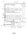
- FIG. 1 is a schematic cross-sectional view of an automatic dishwasher 10 including a twist-preventing rail system.
- example cambered wheels for use with a double C-channel rail system to provide twist prevention are disclosed herein, the cambered wheels disclosed herein may be used with other rail systems such as, but not limited to, a rail system having a single C-channel and two vertical wheels to mount the rail system to an interior side wall of a dishwasher.
- the example cambered wheels and example twist-preventing rail systems disclosed herein may be used to hold utensil holders, the example cambered wheels and twist-preventing rail systems may be used to hold other items such as a dishwasher drawer and/or any other slidably mounted object (e.g., a trash can, a storage drawer, etc.).
- the cambered wheels are mounted to the utensil rack in the examples disclosed herein, the cambered wheels may alternatively be mounted to the interior side wall of a dishwasher.
- the dishwasher 10 includes a cabinet 12 defining an interior.
- the cabinet 12 may be a chassis/frame with or without panels attached, respectively.
- a controller 14 may be located within the cabinet 12 and may be operably coupled with various components of the dishwasher 10 to implement one or more cycles of operation.
- a control panel or user interface 16 may be provided on the dishwasher 10 and coupled with the controller 14.
- the user interface 16 may include operational controls such as dials, lights, switches, and displays enabling a user to input commands, such as a cycle of operation, to the controller 14 and receive information.
- a tub 18 is located within the cabinet 12 and at least partially defines a treating chamber 20 with an access opening in the form of an open face.
- a cover illustrated as a door 22, may be hingedly mounted to the cabinet 12 and may move between an opened position, as shown in FIG. 2 , wherein the user may access the treating chamber 20, and a closed position, as shown in FIG. 1 , wherein the door 22 covers or closes the open face of the treating chamber 20.
- Utensil holders in the form of upper and lower racks 24, 26 are located within the treating chamber 20 and receive utensils for treatment.
- the racks 24, 26 are mounted for slidable movement in and out of the treating chamber 20 for ease of loading and unloading.
- utensil(s) is intended to be generic to any item, single or plural, that may be treated in the dishwasher 10, including, without limitation; dishes, plates, pots, bowls, pans, glassware, and silverware. While not shown, additional utensil holders, such as a silverware basket on the interior of the door 22, may also be provided.
- a spraying system 28 may be provided for spraying liquid into the treating chamber 20, and is illustrated in the form of an upper sprayer 30, a mid-level sprayer 32, a lower rotatable spray arm 34, and a spray manifold 36.
- the upper sprayer 30 may be located above the upper rack 24 and is illustrated as a fixed spray nozzle that sprays liquid downwardly within the treating chamber 20.
- Mid-level rotatable sprayer 32 and lower rotatable spray arm 34 are located, respectively, beneath the upper rack 24 and the lower rack 26 and are illustrated as rotating spray arms.
- the mid-level spray arm 32 may provide a liquid spray upwardly through the bottom of the upper rack 24.
- the lower rotatable spray arm 34 may provide a liquid spray upwardly through the bottom of the lower rack 26.
- the mid-level rotatable sprayer 32 may optionally also provide a liquid spray downwardly onto the lower rack 26, but for purposes of simplification, this will not be illustrated herein.
- the spray manifold 36 may be fixedly mounted to the tub 18 adjacent to the lower rack 26 and may provide a liquid spray laterally through a side of the lower rack 26.
- the spray manifold 36 may not be limited to this position; rather, the spray manifold 36 may be located in virtually any part of the treating chamber 20.
- the spray manifold 36 may include multiple spray nozzles having apertures configured to spray wash liquid towards the lower rack 26.
- the spray nozzles may be fixed or rotatable with respect to the tub 18. Suitable spray manifolds are set forth in detail in U.S. Patent No. 7,445,013, filed June 17, 2003 , and titled “Multiple Wash Zone Dishwasher," and U.S. Patent No. 7,523,758, filed December 30, 2004 , and titled "Dishwasher Having Rotating Zone Wash Sprayer.”
- a liquid recirculation system may be provided for recirculating liquid from the treating chamber 20 to the spraying system 28.
- the recirculation system may include a sump 38 and a pump assembly 40.
- the sump 38 collects the liquid sprayed in the treating chamber 20 and may be formed by a sloped or recessed portion of a bottom wall 42 of the tub 18.
- the pump assembly 40 may include both a drain pump 44 and a recirculation pump 46.
- the drain pump 44 may draw liquid from the sump 38 and pump the liquid out of the dishwasher 10 to a household drain line 48.
- the recirculation pump 46 may draw liquid from the sump 38 and pump the liquid to the spraying system 28 to supply liquid into the treating chamber 20.
- the pump assembly 40 may include a single pump configured to selectively supply wash liquid to either the spraying system 28 or the drain line 48, such as by configuring the pump to rotate in opposite directions, or by providing a suitable valve system.
- a liquid supply system may include a water supply conduit coupled with a household water supply for supplying water to the sump 38.
- a heating system having a heater 50 may be located within or near a lower portion of the tub 18 for heating liquid contained therein.
- FIG. 2 is a front perspective view of the automatic dishwasher 10 of FIG. 1 , with the door 22 in an open position.
- the tub 18 includes spaced-apart opposing side walls 52.
- At least the upper rack 24 is coupled to the tub 18 by a rail system 54 for mounting the upper rack 24 to the side walls 52 of the tub 18.
- At least the side walls 52 of the tub 18 can be flexible, for example, by limiting the underlying support structure (not shown) in the vicinity of the rail system 54, thereby, allowing the side walls 52 to flex, and/or by being constructed of in a flexible thin panel of material, such as polypropylene or stainless steel.
- the rail system 54 comprises a pair of rail assemblies 56 (see FIG. 3 ), one associated with each side wall 52 of the tub 18 and which couples one lateral side of the rack 24 to the tub 18. While not described herein, the lower rack 26 can also be coupled to the side walls 52 of the tub 18 by a similar rail system 54.
- the racks 24, 26 are moveable between a first or cycle position in which the racks 24, 26 are received within the treating chamber 20 and the door 22 can be closed in order to begin a cycle of operation, and a second or loading position in which the door 22 is open and the racks 24, 26 are slid at least partially out of the treating chamber 20 for ease of loading and unloading utensils from the racks 24, 26.
- the lower rack 26 is shown in the first/cycle position
- the upper rack 24 is shown in the second/loading position.
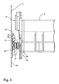
- FIG. 3 is a front view of a portion of the dishwasher 10, illustrating the upper rack 24 mounted to the dishwasher 10 by the rail assembly 56.
- Each rail assembly 56 includes at least one first wheel 58 mounted to the side wall 52 of the tub 18 and at least one second wheel 60 mounted to the rack 24, and a track 62 which is configured to receive both wheels 58, 60 to slidably mount the rack 24 to the tub 18.
- the track 62 can have a first C-shaped channel 64 and a second C-shaped channel 66 arranged in a back-to-back relationship, which each C-shaped channel 64, 66 adapted to receive one of the wheels 58, 60.
- each rail assembly 56 further includes one or more tub mounting bracket(s) 68 and a rack mount 70.
- the tub mounting bracket(s) 68 are fixedly mounted to the side wall 52 of the tub 18, and mount the first wheel 68, which is received within the first C-shaped channel 64 of the track 62.
- the rack mount 70 attaches to the rack 24 and carries the second wheel 60, which is received within the second C-shaped channel 66 of the track 62.
- the C-shaped channels 64, 66 of the track 62 can be separated by a partition 72 extending between the channels 64, 66, thereby dividing the channels 64, 66 into separate raceways for the wheels 58,60.
- the wheel 60 (which is rotatably mounted to the upper rack 24) is intentionally cambered.
- the angle at which the wheel 60 is cambered is selected so that substantially all of the slop between components (i.e., track 62, wheel 62, axle, etc.) is taken out and the rail 62 is substantially straight.
- the wheel 60 is cambered downward by 3 degrees.
- the ability of a downward force applied to the rail assembly 56 due to, for example, the weight of utensils in the upper rack 24, to rotate, twist or deflect the rail 62 is substantially eliminated or reduced.
- a downward force will rotate or twist the rail 62 until the slop is removed.
- FIG. 4 is an exploded view of the rail assembly 56 from FIG. 3 .
- the first C-shaped channel 64 can be defined by a first rail 74 and the second C-shaped channel 66 can be defined by a second rail 76.
- the first and second rails 76 have a similar construction, except that they are mirror image of each other when installed; thus, the rails 74, 76 will not be described separately.
- Each rail 74, 76 can include an elongated body having a generally vertical middle wall 78, an upper L-shaped wall 80, and a lower L-shaped wall 82 extending from and along the middle wall 78, such that a cross-section of the rail 74, 76 has a C-shape.
- An elongated opening 84 is positioned opposite the middle wall 78, between the L-shaped walls 80, 82.
- a stop 86 is formed at one end of the middle wall 78.
- the first and second rails 74, 76 can be fixedly attached to each other such that the rails 74, 76 do not move relative to each other.
- the attachment of the rails 74, 76 can be accomplished with any suitable method, including, but not limited to, welding, mechanical lock, or rivets.
- the rails 74, 76 can include fastener openings 87 for receiving mechanical fasteners (not shown) for attaching the rails to each other.
- the first and second rails 74, 76 can be attached to each other in a position such that the middle walls 78 of the rails 74, 76 are adjacent to each other to arrange the first and second C-shaped channels 64, 66 in the back-to-back relationship.
- the adjacent middle walls 78 can together define the partition 72 (see in FIG. 3 ), with the openings 84 facing opposite directions. It is noted that the adjacent middle walls 78 can be replaced with a single partition 72 between the first and second C-shaped channels 64, 66.
- the rails 74, 76 can include one or more port(s) 88 formed through the middle wall 78, which provide for the passage of liquid through the middle wall 78. Soil can accumulate in or around the rail assembly 56, and the ports 88 allow liquid to pass through the track 62 to wash out the soil. As illustrated, the middle wall 78 can include multiple ports 88 which extend substantially along the length of the rail 74, 76.
- the ports 88 in the rails 74, 76 can be positioned to at least partially overlap, to provide for a continuous passage through the track 62. It is noted, however, that the ends of the first and second rails 74, 76 may be offset from each other, and, therefore, the ports 88 in the first and second rails 74, 76 may not be positioned at the same distances along each rail 74, 76, but rather may be relatively spaced based on the offset in order for the ports 88 to overlap.
- the rails 74, 76 can further include one or more glide rib(s) 90 (see FIG. 5 for an enlarged view) at least partially defining the C-shaped channels 64, 66, which function to maintain a space between the wheels 58, 60 and the middle wall 78 to ensure that the wheels 58, 60 do not contact the mechanical fasteners (not shown) received in the fastener openings 87, or the ports 88, thereby, ensuring that the rails 74, 76 slide smoothly over the wheels 58, 60.
- Each rail 74, 76 can include two vertically-spaced glide ribs 90 that extend horizontally along the length of the middle wall 78. The ribs 90 extend into the space defining the C-shaped channels 64, 66.
- the rail assembly 56 includes the two tub mounting brackets 68.
- Each bracket 68 includes a vertically elongated flange 92 having two spaced openings 94 for receiving fasteners (not shown) for attaching the bracket 68 to the tub side wall 52, and a wheel interface 96 between the openings 94 for mounting the first wheel 58.
- the bracket 68 can also include a recessed portion 98 to allow clearance for the rail 74 and for the wheel 58 to rotate. Therefore, two first wheels 58 are fixed in place relative to the tub 18, but rotatable. Both wheels 58 are received in the first C-shaped channel 64, thereby allowing the first rail 74 to slide along the wheels 58 relative to the tub 18 and brackets 68. Since the second rail 76 is fixedly attached to the first rail 74, the second rail 76 will also slide relative to the tub 18 and brackets 68.
- the rack mount 70 is mounted to one side of the rack 24 and includes two wheel interfaces 100 that each mount one of the second wheels 60; therefore, two second wheels 60 are fixed in place relative to the rack 24, but rotatable. Both wheels 60 are received in the second C-shaped channel 66, thereby allowing the rack 24 to slide relative to the rails 74, 76, and the tub 18.
- the rack mount 70 can further comprise a rack height adjuster 102, as shown in the illustrated embodiment, that is configured to adjust the vertical height of the rack 24 relative to the track 62, thereby adjusting the vertical position of the rack 24 within the treating chamber 20.
- rack height adjusters are well known in the art, and will not be described further herein. Details of a suitable rack height adjuster can be found in U.S. Patent No.
- the rack mount 70 can alternatively be a stationary mount that couples the rack 24 with the track 62, but does not allow for height adjustment of the rack.
- the rack mount 70 can be flexible, for example, by being constructed of a flexible material such as polypropylene or acetal. The flexibility of the rack mount 70 is also affected by the geometry of the rack mount 70.
- Each of the wheels 58, 60 include a wheel hub 104 rotatably coupled to an axle 106.
- the first and second wheels 58, 60 have a similar construction, except that they are associated with different rails 74, 76; therefore, the features of the wheels 58, 60 will not be described separately.
- the axles 106 of the wheels 58, 60 are received by the wheel interfaces 96, 100, respectively, on the brackets 68 and rack mount 70.
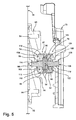
- FIG. 5 is a cross-sectional view through the rail assembly 56.
- the wheel hub 104 includes a central portion 108 having a bore 110 for receiving the axle 106, a rim 112 defining a peripheral rotational surface 114, and a neck portion 116 connecting the rim 112 to the central portion 108.
- the axle 106 includes a first end 118 which is received in the wheel interface 96, 100 and has a flange 120 abutting an inner surface of the wheel interface 96, 100, and a second end 122 which is received in the bore 110 of the hub 104 and has a flange 124 abutting a surface of the central portion 108.
- the second end 122 is illustrated as having a slightly larger diameter than the first end 118, although the specific configuration of the axle 106 can be determined based on the configurations of the wheel interface 96, 100 and wheel hub 104.
- the wheel hubs 104 are received within the C-shaped channels 64, 66, with the rims 112 resting on, and, therefore, moveable along, the lower wall 82 of the rails 74, 76.
- the glide ribs 90 confront the face of the rim 112, and prevent the wheel hubs 104 from touching the middle wall 78 of the rails 74, 76 in order to maintain a space between the wheel hubs 104 and the middle walls 78 to ensure that the wheels 58, 60 do not contact the mechanical fasteners (not shown) received in the fastener openings 87, or the ports 88, thereby, ensuring that the rails 74, 76 slide smoothly over the wheels 58, 60.
- the materials for the wheel hub 104 and axle 106 can be selected to have a low coefficient of friction, thereby reducing the noise associated with and force required to rotate the wheel hub 104 relative to the axle 106.
- the materials for the wheel hub 104 and axle 106 may be selected to have a coefficient of friction less than 0.25, more specifically, equal to or less than 0.15, or, even more specifically, ranging between 0.05 to 0.15.
- the axle 106 is a metal axle, illustrated in the drawings as a metal rivet.
- the metal rivet can mount a plastic wheel hub 104 for rotational movement.
- the use of a metal rivet or axle 106 can further reduce the noise associated with sliding the rail assembly 56, because the part tolerances associated with a metal axle 106 are smaller than associated with previous plastic axles.
- Plastic axles are snap-fit with wheel hubs, which require larger part tolerances in order to accommodate the snap action.
- a larger part tolerance means that there are larger gaps between the axle and hub, which can produce a rattling noise when the wheel hub spins on the axle.
- Smaller part tolerance means that there are smaller gaps between the wheel hub 104 and axle 106, thereby reducing the rattling noise produced when the wheel hub 104 spins on the axle 106.
- Another reason that noise is reduced using a metal axle 106 is that prior plastic axles use glass or mineral fillers to stiffen the axle, which generate a lot of noise against the rotating wheel hub.
- One example of specific materials used for the metal axle 106 is stainless steel, and for the wheel hub 104 is acetal, also known as polyoxymethylene or POM. Stainless steel and acetal have a coefficient of friction of 0.15.
- the wheel 60 (which is rotatably mounted to the upper rack 24) is intentionally cambered.
- the angle at which the wheel 60 is cambered is selected so that substantially all of the slop between components (i.e., track 62, wheel hub 105, axle 106, etc.) is taken out and the rail 62 is substantially straight.
- the wheel 60 is cambered downward by 3 degrees.
- the ability of a downward force applied to the rail assembly 56 due to, for example, the weight of utensils in the upper rack 24, to rotate, twist or deflect the rail 62 is substantially eliminated or reduced.
- a downward force will rotate or twist the rail 62 until the slop is removed.
Landscapes
- Washing And Drying Of Tableware (AREA)
Abstract
Description
- This disclosure relates generally to rack mounting arrangements for dishwashers, and more particularly to rail systems that prevent twisting of the rail system.
- Dishwashers include a treating chamber in which utensils are placed to be washed according to an automatic cycle of operation. Typically, at least one rack is located in the treating chamber for holding utensils to be cleaned. In dishwashers where the treating chamber is accessible through a moveable door, one or more rack(s) can be slidably mounted within the treating chamber in such a manner that at least a major portion of the rack(s) can be slid substantially beyond the treating chamber to ease the loading of the racks.
- A disclosed example dishwasher includes a tub at least partially defining a treating chamber and having at least one side, a rack for holding utensils for treatment within the treating chamber, a first wheel mounted to the at least one side of the tub, a second wheel mounted to the rack at an angle other than perpendicular, and a track having a first C-shaped channel receiving the first wheel and a second C-shaped channel receiving the second wheel to slidably mount the rack to the tub, with the first and second C-shaped channels in a back-to-back relationship.
-
-
FIG. 1 is a schematic cross-sectional view of an automatic dishwasher including a twist-preventing rail system. -
FIG. 2 is a front isometric view of the automatic dishwasher ofFIG. 1 illustrating an upper rack mounted to the dishwasher by the twist-preventing rail system ofFIG. 1 . -
FIG. 3 is a front view of the twist-preventing rail assembly ofFIG. 2 . -
FIG. 4 is an exploded view of the rail assembly ofFIG. 3 . -
FIG. 5 is a cross-sectional view through the rail assembly ofFIG. 3 . - The examples disclosed herein provide a rail system for a dishwasher that has improved performance over previous rail systems. Advantages that may be realized by the example rail systems disclosed herein are that the rail system will twist less thereby increasing visual appeal and perceived quality, the rail system may operate more smoothly, and/or rubbing of a tub seal by the rail system may be reduced.
-
FIG. 1 is a schematic cross-sectional view of anautomatic dishwasher 10 including a twist-preventing rail system. While example cambered wheels for use with a double C-channel rail system to provide twist prevention are disclosed herein, the cambered wheels disclosed herein may be used with other rail systems such as, but not limited to, a rail system having a single C-channel and two vertical wheels to mount the rail system to an interior side wall of a dishwasher. Moreover, while the example cambered wheels and example twist-preventing rail systems disclosed herein may be used to hold utensil holders, the example cambered wheels and twist-preventing rail systems may be used to hold other items such as a dishwasher drawer and/or any other slidably mounted object (e.g., a trash can, a storage drawer, etc.). Further still, while the cambered wheels are mounted to the utensil rack in the examples disclosed herein, the cambered wheels may alternatively be mounted to the interior side wall of a dishwasher. - The
dishwasher 10 includes acabinet 12 defining an interior. Depending on whether thedishwasher 10 is a stand-alone or built-in, thecabinet 12 may be a chassis/frame with or without panels attached, respectively. - A
controller 14 may be located within thecabinet 12 and may be operably coupled with various components of thedishwasher 10 to implement one or more cycles of operation. A control panel oruser interface 16 may be provided on thedishwasher 10 and coupled with thecontroller 14. Theuser interface 16 may include operational controls such as dials, lights, switches, and displays enabling a user to input commands, such as a cycle of operation, to thecontroller 14 and receive information. - A
tub 18 is located within thecabinet 12 and at least partially defines a treatingchamber 20 with an access opening in the form of an open face. A cover, illustrated as adoor 22, may be hingedly mounted to thecabinet 12 and may move between an opened position, as shown inFIG. 2 , wherein the user may access the treatingchamber 20, and a closed position, as shown inFIG. 1 , wherein thedoor 22 covers or closes the open face of the treatingchamber 20. - Utensil holders in the form of upper and
lower racks chamber 20 and receive utensils for treatment. Theracks chamber 20 for ease of loading and unloading. As used in this description, the term "utensil(s)" is intended to be generic to any item, single or plural, that may be treated in thedishwasher 10, including, without limitation; dishes, plates, pots, bowls, pans, glassware, and silverware. While not shown, additional utensil holders, such as a silverware basket on the interior of thedoor 22, may also be provided. - A
spraying system 28 may be provided for spraying liquid into the treatingchamber 20, and is illustrated in the form of anupper sprayer 30, amid-level sprayer 32, a lowerrotatable spray arm 34, and aspray manifold 36. Theupper sprayer 30 may be located above theupper rack 24 and is illustrated as a fixed spray nozzle that sprays liquid downwardly within the treatingchamber 20. Mid-levelrotatable sprayer 32 and lowerrotatable spray arm 34 are located, respectively, beneath theupper rack 24 and thelower rack 26 and are illustrated as rotating spray arms. Themid-level spray arm 32 may provide a liquid spray upwardly through the bottom of theupper rack 24. The lowerrotatable spray arm 34 may provide a liquid spray upwardly through the bottom of thelower rack 26. The mid-levelrotatable sprayer 32 may optionally also provide a liquid spray downwardly onto thelower rack 26, but for purposes of simplification, this will not be illustrated herein. - The
spray manifold 36 may be fixedly mounted to thetub 18 adjacent to thelower rack 26 and may provide a liquid spray laterally through a side of thelower rack 26. Thespray manifold 36 may not be limited to this position; rather, thespray manifold 36 may be located in virtually any part of the treatingchamber 20. While not illustrated herein, thespray manifold 36 may include multiple spray nozzles having apertures configured to spray wash liquid towards thelower rack 26. The spray nozzles may be fixed or rotatable with respect to thetub 18. Suitable spray manifolds are set forth in detail inU.S. Patent No. 7,445,013, filed June 17, 2003 , and titled "Multiple Wash Zone Dishwasher," andU.S. Patent No. 7,523,758, filed December 30, 2004 , and titled "Dishwasher Having Rotating Zone Wash Sprayer." - A liquid recirculation system may be provided for recirculating liquid from the treating
chamber 20 to thespraying system 28. The recirculation system may include asump 38 and apump assembly 40. Thesump 38 collects the liquid sprayed in the treatingchamber 20 and may be formed by a sloped or recessed portion of abottom wall 42 of thetub 18. Thepump assembly 40 may include both adrain pump 44 and arecirculation pump 46. - The
drain pump 44 may draw liquid from thesump 38 and pump the liquid out of thedishwasher 10 to ahousehold drain line 48. Therecirculation pump 46 may draw liquid from thesump 38 and pump the liquid to thespraying system 28 to supply liquid into the treatingchamber 20. While thepump assembly 40 is illustrated as having separate drain andrecirculation pumps pump assembly 40 may include a single pump configured to selectively supply wash liquid to either thespraying system 28 or thedrain line 48, such as by configuring the pump to rotate in opposite directions, or by providing a suitable valve system. While not shown, a liquid supply system may include a water supply conduit coupled with a household water supply for supplying water to thesump 38. A heating system having aheater 50 may be located within or near a lower portion of thetub 18 for heating liquid contained therein. -
FIG. 2 is a front perspective view of theautomatic dishwasher 10 ofFIG. 1 , with thedoor 22 in an open position. Thetub 18 includes spaced-apartopposing side walls 52. At least theupper rack 24 is coupled to thetub 18 by arail system 54 for mounting theupper rack 24 to theside walls 52 of thetub 18. At least theside walls 52 of thetub 18 can be flexible, for example, by limiting the underlying support structure (not shown) in the vicinity of therail system 54, thereby, allowing theside walls 52 to flex, and/or by being constructed of in a flexible thin panel of material, such as polypropylene or stainless steel. - The
rail system 54 comprises a pair of rail assemblies 56 (seeFIG. 3 ), one associated with eachside wall 52 of thetub 18 and which couples one lateral side of therack 24 to thetub 18. While not described herein, thelower rack 26 can also be coupled to theside walls 52 of thetub 18 by asimilar rail system 54. Theracks racks chamber 20 and thedoor 22 can be closed in order to begin a cycle of operation, and a second or loading position in which thedoor 22 is open and theracks chamber 20 for ease of loading and unloading utensils from theracks FIG. 2 , thelower rack 26 is shown in the first/cycle position, and theupper rack 24 is shown in the second/loading position. -
FIG. 3 is a front view of a portion of thedishwasher 10, illustrating theupper rack 24 mounted to thedishwasher 10 by therail assembly 56. Eachrail assembly 56 includes at least onefirst wheel 58 mounted to theside wall 52 of thetub 18 and at least onesecond wheel 60 mounted to therack 24, and atrack 62 which is configured to receive bothwheels rack 24 to thetub 18. Thetrack 62 can have a first C-shaped channel 64 and a second C-shaped channel 66 arranged in a back-to-back relationship, which each C-shaped channel wheels - In the illustrated embodiment, each
rail assembly 56 further includes one or more tub mounting bracket(s) 68 and arack mount 70. The tub mounting bracket(s) 68 are fixedly mounted to theside wall 52 of thetub 18, and mount thefirst wheel 68, which is received within the first C-shaped channel 64 of thetrack 62. Therack mount 70 attaches to therack 24 and carries thesecond wheel 60, which is received within the second C-shapedchannel 66 of thetrack 62. The C-shapedchannels track 62 can be separated by apartition 72 extending between thechannels channels wheels - Compared to previous rail systems, the wheel 60 (which is rotatably mounted to the upper rack 24) is intentionally cambered. The angle at which the
wheel 60 is cambered is selected so that substantially all of the slop between components (i.e.,track 62,wheel 62, axle, etc.) is taken out and therail 62 is substantially straight. In some examples, thewheel 60 is cambered downward by 3 degrees. By removing the slop, the ability of a downward force applied to therail assembly 56 due to, for example, the weight of utensils in theupper rack 24, to rotate, twist or deflect therail 62 is substantially eliminated or reduced. In stark contrast, when thewheel 60 is not cambered, a downward force will rotate or twist therail 62 until the slop is removed. -
FIG. 4 is an exploded view of therail assembly 56 fromFIG. 3 . The first C-shapedchannel 64 can be defined by afirst rail 74 and the second C-shapedchannel 66 can be defined by asecond rail 76. In the illustrated embodiment, the first andsecond rails 76 have a similar construction, except that they are mirror image of each other when installed; thus, therails rail middle wall 78, an upper L-shapedwall 80, and a lower L-shapedwall 82 extending from and along themiddle wall 78, such that a cross-section of therail elongated opening 84 is positioned opposite themiddle wall 78, between the L-shapedwalls stop 86 is formed at one end of themiddle wall 78. - The first and
second rails rails rails rails fastener openings 87 for receiving mechanical fasteners (not shown) for attaching the rails to each other. As illustrated, the first andsecond rails middle walls 78 of therails channels middle walls 78 can together define the partition 72 (see inFIG. 3 ), with theopenings 84 facing opposite directions. It is noted that the adjacentmiddle walls 78 can be replaced with asingle partition 72 between the first and second C-shapedchannels - The
rails middle wall 78, which provide for the passage of liquid through themiddle wall 78. Soil can accumulate in or around therail assembly 56, and theports 88 allow liquid to pass through thetrack 62 to wash out the soil. As illustrated, themiddle wall 78 can includemultiple ports 88 which extend substantially along the length of therail - The
ports 88 in therails track 62. It is noted, however, that the ends of the first andsecond rails ports 88 in the first andsecond rails rail ports 88 to overlap. - The
rails FIG. 5 for an enlarged view) at least partially defining the C-shapedchannels wheels middle wall 78 to ensure that thewheels fastener openings 87, or theports 88, thereby, ensuring that therails wheels rail glide ribs 90 that extend horizontally along the length of themiddle wall 78. Theribs 90 extend into the space defining the C-shapedchannels - In the illustrated embodiment, the
rail assembly 56 includes the twotub mounting brackets 68. Eachbracket 68 includes a vertically elongatedflange 92 having two spacedopenings 94 for receiving fasteners (not shown) for attaching thebracket 68 to thetub side wall 52, and awheel interface 96 between theopenings 94 for mounting thefirst wheel 58. Thebracket 68 can also include a recessedportion 98 to allow clearance for therail 74 and for thewheel 58 to rotate. Therefore, twofirst wheels 58 are fixed in place relative to thetub 18, but rotatable. Bothwheels 58 are received in the first C-shapedchannel 64, thereby allowing thefirst rail 74 to slide along thewheels 58 relative to thetub 18 andbrackets 68. Since thesecond rail 76 is fixedly attached to thefirst rail 74, thesecond rail 76 will also slide relative to thetub 18 andbrackets 68. - The
rack mount 70 is mounted to one side of therack 24 and includes twowheel interfaces 100 that each mount one of thesecond wheels 60; therefore, twosecond wheels 60 are fixed in place relative to therack 24, but rotatable. Bothwheels 60 are received in the second C-shapedchannel 66, thereby allowing therack 24 to slide relative to therails tub 18. The rack mount 70 can further comprise arack height adjuster 102, as shown in the illustrated embodiment, that is configured to adjust the vertical height of therack 24 relative to thetrack 62, thereby adjusting the vertical position of therack 24 within the treatingchamber 20. Such rack height adjusters are well known in the art, and will not be described further herein. Details of a suitable rack height adjuster can be found inU.S. Patent No. 7,410,228 to Dickson et al., issued August 12, 2008 . The rack mount 70 can alternatively be a stationary mount that couples therack 24 with thetrack 62, but does not allow for height adjustment of the rack. The rack mount 70 can be flexible, for example, by being constructed of a flexible material such as polypropylene or acetal. The flexibility of therack mount 70 is also affected by the geometry of therack mount 70. - Each of the
wheels wheel hub 104 rotatably coupled to anaxle 106. In the illustrated embodiment, the first andsecond wheels different rails wheels axles 106 of thewheels brackets 68 andrack mount 70. -
FIG. 5 is a cross-sectional view through therail assembly 56. Thewheel hub 104 includes acentral portion 108 having abore 110 for receiving theaxle 106, arim 112 defining a peripheralrotational surface 114, and aneck portion 116 connecting therim 112 to thecentral portion 108. - The
axle 106 includes afirst end 118 which is received in thewheel interface flange 120 abutting an inner surface of thewheel interface second end 122 which is received in thebore 110 of thehub 104 and has aflange 124 abutting a surface of thecentral portion 108. Thesecond end 122 is illustrated as having a slightly larger diameter than thefirst end 118, although the specific configuration of theaxle 106 can be determined based on the configurations of thewheel interface wheel hub 104. - The
wheel hubs 104 are received within the C-shapedchannels rims 112 resting on, and, therefore, moveable along, thelower wall 82 of therails glide ribs 90 confront the face of therim 112, and prevent thewheel hubs 104 from touching themiddle wall 78 of therails wheel hubs 104 and themiddle walls 78 to ensure that thewheels fastener openings 87, or theports 88, thereby, ensuring that therails wheels - The materials for the
wheel hub 104 andaxle 106 can be selected to have a low coefficient of friction, thereby reducing the noise associated with and force required to rotate thewheel hub 104 relative to theaxle 106. For example, the materials for thewheel hub 104 andaxle 106 may be selected to have a coefficient of friction less than 0.25, more specifically, equal to or less than 0.15, or, even more specifically, ranging between 0.05 to 0.15. - In some examples the
axle 106 is a metal axle, illustrated in the drawings as a metal rivet. The metal rivet can mount aplastic wheel hub 104 for rotational movement. The use of a metal rivet oraxle 106 can further reduce the noise associated with sliding therail assembly 56, because the part tolerances associated with ametal axle 106 are smaller than associated with previous plastic axles. Plastic axles are snap-fit with wheel hubs, which require larger part tolerances in order to accommodate the snap action. A larger part tolerance means that there are larger gaps between the axle and hub, which can produce a rattling noise when the wheel hub spins on the axle. Smaller part tolerance means that there are smaller gaps between thewheel hub 104 andaxle 106, thereby reducing the rattling noise produced when thewheel hub 104 spins on theaxle 106. Another reason that noise is reduced using ametal axle 106 is that prior plastic axles use glass or mineral fillers to stiffen the axle, which generate a lot of noise against the rotating wheel hub. One example of specific materials used for themetal axle 106 is stainless steel, and for thewheel hub 104 is acetal, also known as polyoxymethylene or POM. Stainless steel and acetal have a coefficient of friction of 0.15. - Compared to previous rail systems, the wheel 60 (which is rotatably mounted to the upper rack 24) is intentionally cambered. The angle at which the
wheel 60 is cambered is selected so that substantially all of the slop between components (i.e.,track 62, wheel hub 105,axle 106, etc.) is taken out and therail 62 is substantially straight. In some examples, thewheel 60 is cambered downward by 3 degrees. By removing the slop, the ability of a downward force applied to therail assembly 56 due to, for example, the weight of utensils in theupper rack 24, to rotate, twist or deflect therail 62 is substantially eliminated or reduced. In stark contrast, when thewheel 60 is not cambered, a downward force will rotate or twist therail 62 until the slop is removed. - An exemplary operation of the
example rail system 54 is described in co-pending relatedU.S. Patent Application Serial No. 13/329,860, which was filed on December 19, 2011 - Although certain example methods, apparatus and articles of manufacture have been described herein, the scope of coverage of this patent is not limited thereto.
Claims (12)
- A dishwasher (10) comprising:a tub (18) at least partially defining a treating chamber (20) and having at least one side (52);a rack (24, 26) for holding utensils for treatment within the treating chamber (20);a first wheel (58) mounted to the at least one side (52) of the tub (18);a second wheel (60) mounted to the rack (24, 26) at an angle other than perpendicular; anda track (62) having a first C-shaped channel (64) receiving the first wheel (58) and a second C-shaped channel (66) receiving the second wheel (60) to slidably mount the rack (24, 26) to the tub, with the first and second C-shaped channels (64, 66) in a back-to-back relationship.
- The dishwasher of claim 1, wherein the angle is selected to substantially eliminate slop between the second C-shaped channel (66) and the second wheel (60).
- The dishwasher of claim 1 or 2, further comprising a partition (72) between the first and second C-shaped channels (64, 66).
- The dishwasher of claim 3, wherein the partition (72) comprises at least one port (88) to provide for the passage of liquid through the partition.
- The dishwasher of claim 3 or 4, wherein the partition (72) comprises a first wall at least partially defining the first C-shaped channel (64) and a second wall at least partially defining the second C-shaped channel (66).
- The dishwasher of claim 1, wherein the track (62) comprises a first C-shapedrail (74) defining the first C-shaped channel (64) and a second C-shaped rail (76) defining the second C-shaped channel (66).
- The dishwasher of claim 6, wherein the first C-shaped rail (74) comprises a first opening for receiving the first wheel (58) and the second C-shaped rail (76) comprises a second opening for receiving the second wheel (60), wherein the first and second openings face opposite directions.
- The dishwasher of claim 1, wherein the track (62) comprises at least one first glide rib (90) at least partially defining the first C-shaped channel (64) and at least one second glide rib (90) at least partially defining the second C-shaped channel (66).
- The dishwasher of claim 1, further comprising a bracket (68) coupled to the at least one side of the tub (18), wherein the first wheel (58) is fixedly mounted to the bracket (68) to mount the first wheel to the at least one side of the tub (98).
- The dishwasher of claim 1, further comprising a height adjuster (102) coupled to the rack (24, 26), wherein the second wheel (60) is fixedly mounted to the height adjuster (102) to mount the second wheel (60) to the rack (24, 26).
- The dishwasher of claim 1, further comprising a stationary mount (70) coupled to the rack (24, 26), wherein the second wheel (60) is fixedly mounted to the stationary mount (70) to mount the second wheel (60) to the rack (24, 26).
- The dishwasher of claim 1, further comprising a flexible rack mount coupled to the rack (24, 26), wherein the second wheel (60) is fixedly mounted to the flexible rack mount to mount the second wheel (60) to the rack (24, 26).
Applications Claiming Priority (1)
| Application Number | Priority Date | Filing Date | Title |
|---|---|---|---|
| US13/685,763 US8915560B2 (en) | 2012-11-27 | 2012-11-27 | Twist-preventing apparatus for mounting a rack in a dishwasher |
Publications (2)
| Publication Number | Publication Date |
|---|---|
| EP2735255A1 true EP2735255A1 (en) | 2014-05-28 |
| EP2735255B1 EP2735255B1 (en) | 2016-05-18 |
Family
ID=49724463
Family Applications (1)
| Application Number | Title | Priority Date | Filing Date |
|---|---|---|---|
| EP13194558.6A Not-in-force EP2735255B1 (en) | 2012-11-27 | 2013-11-27 | Twist-preventing apparatus for mounting a rack in a dishwasher |
Country Status (3)
| Country | Link |
|---|---|
| US (1) | US8915560B2 (en) |
| EP (1) | EP2735255B1 (en) |
| PL (1) | PL2735255T3 (en) |
Cited By (2)
| Publication number | Priority date | Publication date | Assignee | Title |
|---|---|---|---|---|
| CN106175189A (en) * | 2016-08-24 | 2016-12-07 | 辽东学院 | Compound experiment glass drying oven preserver and using method |
| WO2017042277A1 (en) * | 2015-09-08 | 2017-03-16 | Jet Aviation Ag | Dishwasher system |
Families Citing this family (16)
| Publication number | Priority date | Publication date | Assignee | Title |
|---|---|---|---|---|
| KR102596001B1 (en) * | 2017-01-05 | 2023-11-01 | 엘지전자 주식회사 | drawer rail and a home appliance having the same |
| US10582829B2 (en) | 2017-10-30 | 2020-03-10 | Whirlpool Corporation | Dishwasher with vertically adjustable dish rack |
| US10004381B1 (en) * | 2017-11-02 | 2018-06-26 | Haier Us Appliance Solutions, Inc. | Rack mounting features for a dishwasher appliance |
| US10174785B1 (en) | 2017-11-15 | 2019-01-08 | Electrolux Home Products, Inc. | Wheel bushing |
| US10602909B2 (en) * | 2018-03-01 | 2020-03-31 | Whirlpool Corporation | Stable height adjuster mechanism |
| USD960466S1 (en) * | 2018-03-21 | 2022-08-09 | Whirlpool Corporation | Dishwasher rack assembly |
| US11134824B2 (en) | 2018-08-21 | 2021-10-05 | Illinois Tool Works Inc. | Warewash machine with rack track support member |
| CN111195091B (en) * | 2018-11-16 | 2023-03-03 | 青岛海尔智慧厨房电器有限公司 | Bowl frame and flip structure thereof |
| CN111345761A (en) * | 2018-12-20 | 2020-06-30 | 惠而浦公司 | Dish washing machine |
| CN111657683B (en) * | 2019-03-06 | 2021-10-29 | 宁波方太厨具有限公司 | Cabinet with water receiving device |
| US11058281B2 (en) * | 2019-06-20 | 2021-07-13 | Midea Group Co., Ltd. | Dishwasher including rack position sensor to control capture of rack images by a camera |
| KR102753378B1 (en) * | 2019-09-18 | 2025-01-10 | (주)세고스 | Rail device for dishwasher |
| US11375874B2 (en) | 2020-03-30 | 2022-07-05 | Whirlpool Corporation | Dishwasher with a dish rack and utensil caddy |
| US11712147B2 (en) * | 2020-12-01 | 2023-08-01 | Haier Us Appliance Solutions, Inc. | Rack mounting features for a dishwasher appliance |
| US11771300B2 (en) * | 2021-10-18 | 2023-10-03 | Haier Us Appliance Solutions, Inc. | Universal bracket for supporting racks in a dishwasher appliance |
| US12539015B2 (en) | 2023-09-05 | 2026-02-03 | Midea Group Co., Ltd. | Dishwasher with personalized utensil detection and scanning aids therefor |
Citations (7)
| Publication number | Priority date | Publication date | Assignee | Title |
|---|---|---|---|---|
| US3990756A (en) * | 1975-07-01 | 1976-11-09 | General Electric Company | Self-aligning, self-adjusting dishwasher rack |
| EP1321093A2 (en) * | 2001-12-22 | 2003-06-25 | Electrolux Home Products Corporation N.V. | Roller rail for dishwasher rack |
| EP1356759A2 (en) * | 2002-04-23 | 2003-10-29 | Electrolux Home Products Corporation N.V. | Guiding system particularly for domestic appliance drawer type containers, in particular for dishwashers |
| US20060250058A1 (en) * | 2005-03-29 | 2006-11-09 | Whirlpool Corporation | Dishwasher with Utensil Rack and Slides Therefor |
| US7410228B2 (en) | 2004-12-08 | 2008-08-12 | Whirlpool Corporation | Height adjuster mechanism for a dishwasher dish rack |
| US7445013B2 (en) | 2003-06-17 | 2008-11-04 | Whirlpool Corporation | Multiple wash zone dishwasher |
| US7523758B2 (en) | 2003-06-17 | 2009-04-28 | Whirlpool Corporation | Dishwasher having rotating zone wash sprayer |
Family Cites Families (12)
| Publication number | Priority date | Publication date | Assignee | Title |
|---|---|---|---|---|
| US3095250A (en) * | 1961-08-11 | 1963-06-25 | Supreme Steel Equipment Corp | Roller drawer suspension device |
| US3194610A (en) * | 1963-03-27 | 1965-07-13 | Whirlpool Co | Releasably attachable wheel device for use with wire structures |
| US3214227A (en) * | 1964-07-09 | 1965-10-26 | American Can Co | Dispenser |
| US3347612A (en) * | 1966-02-14 | 1967-10-17 | Gen Electric | Rack support system |
| US4449765A (en) * | 1982-06-07 | 1984-05-22 | Whirlpool Corporation | Dishrack wheel assembly for a dishwasher |
| FR2780694B1 (en) * | 1998-07-06 | 2000-08-18 | Alstom | COMPOSITE MATERIAL BOGIE FOR RAIL VEHICLE AND MANUFACTURING METHOD THEREOF |
| US6397863B1 (en) * | 2001-08-29 | 2002-06-04 | General Electric Company | Method and apparatus for coupling a rack to a dishwasher |
| US6755490B2 (en) * | 2001-08-30 | 2004-06-29 | Maytag Corporation | Dishwasher with adjustable rack |
| US7640612B2 (en) * | 2004-01-09 | 2010-01-05 | Schock Metallwerk Gmbh | Device incorporating a chamber through which fluid is adapted to flow and the use of a drawer guide in such a device |
| US7594707B2 (en) * | 2007-08-15 | 2009-09-29 | Whirlpool Corporation | Snap-in bearing rack and pinion system |
| ATE498350T1 (en) * | 2007-12-31 | 2011-03-15 | Arcelik As | HEIGHT-ADJUSTABLE FRAME FOR A DISHWASHER |
| US8813766B2 (en) * | 2011-05-18 | 2014-08-26 | Whirlpool Corporation | Height adjuster mechanism for a dishwasher dish rack |
-
2012
- 2012-11-27 US US13/685,763 patent/US8915560B2/en active Active
-
2013
- 2013-11-27 EP EP13194558.6A patent/EP2735255B1/en not_active Not-in-force
- 2013-11-27 PL PL13194558.6T patent/PL2735255T3/en unknown
Patent Citations (7)
| Publication number | Priority date | Publication date | Assignee | Title |
|---|---|---|---|---|
| US3990756A (en) * | 1975-07-01 | 1976-11-09 | General Electric Company | Self-aligning, self-adjusting dishwasher rack |
| EP1321093A2 (en) * | 2001-12-22 | 2003-06-25 | Electrolux Home Products Corporation N.V. | Roller rail for dishwasher rack |
| EP1356759A2 (en) * | 2002-04-23 | 2003-10-29 | Electrolux Home Products Corporation N.V. | Guiding system particularly for domestic appliance drawer type containers, in particular for dishwashers |
| US7445013B2 (en) | 2003-06-17 | 2008-11-04 | Whirlpool Corporation | Multiple wash zone dishwasher |
| US7523758B2 (en) | 2003-06-17 | 2009-04-28 | Whirlpool Corporation | Dishwasher having rotating zone wash sprayer |
| US7410228B2 (en) | 2004-12-08 | 2008-08-12 | Whirlpool Corporation | Height adjuster mechanism for a dishwasher dish rack |
| US20060250058A1 (en) * | 2005-03-29 | 2006-11-09 | Whirlpool Corporation | Dishwasher with Utensil Rack and Slides Therefor |
Cited By (3)
| Publication number | Priority date | Publication date | Assignee | Title |
|---|---|---|---|---|
| WO2017042277A1 (en) * | 2015-09-08 | 2017-03-16 | Jet Aviation Ag | Dishwasher system |
| CN106175189A (en) * | 2016-08-24 | 2016-12-07 | 辽东学院 | Compound experiment glass drying oven preserver and using method |
| CN106175189B (en) * | 2016-08-24 | 2018-04-20 | 辽东学院 | Compound experiment glassware storage cabinet and application method |
Also Published As
| Publication number | Publication date |
|---|---|
| US20140145573A1 (en) | 2014-05-29 |
| US8915560B2 (en) | 2014-12-23 |
| EP2735255B1 (en) | 2016-05-18 |
| PL2735255T3 (en) | 2016-09-30 |
Similar Documents
| Publication | Publication Date | Title |
|---|---|---|
| EP2735255B1 (en) | Twist-preventing apparatus for mounting a rack in a dishwasher | |
| US9113773B2 (en) | Dishwasher rack assembly with trim assembly | |
| US7168578B2 (en) | Dishwasher rack assemblies | |
| US8485205B2 (en) | Dishwasher with rotating zone wash sprayers | |
| US10076224B2 (en) | Dishwasher | |
| US8007598B2 (en) | Dishwasher having multiple spray zones | |
| US7198054B2 (en) | Dishwasher having a side-by-side rack system | |
| US20180055333A1 (en) | Dishwasher with slidable tine assembly | |
| US20190059693A1 (en) | Dish treating appliance door assembly | |
| US20130152983A1 (en) | Apparatus for mounting a rack in a dishwasher | |
| US9439552B2 (en) | Apparatus for improving door robustness in a dishwasher | |
| EP3348181B1 (en) | Dishwasher guide rail assembly | |
| US10945585B2 (en) | Dishwasher with moveable shelf | |
| US10694924B1 (en) | Dishwasher with guide rail | |
| US10136795B2 (en) | Dish rack retaining clip | |
| EP2432369A1 (en) | A dishwasher comprising a drawer | |
| US9775489B1 (en) | Door assembly for a dishwasher | |
| US10602909B2 (en) | Stable height adjuster mechanism | |
| US10575709B2 (en) | Rack assembly for a dishwasher | |
| US20180103828A1 (en) | Dishwasher guide rail assembly | |
| US10426315B2 (en) | Dishwasher | |
| US9408519B2 (en) | Dishwasher support structures to reduce rotation of a door crown | |
| US10986976B2 (en) | Dishwasher with door latch assembly | |
| US11389047B2 (en) | Dishwasher rack support assembly |
Legal Events
| Date | Code | Title | Description |
|---|---|---|---|
| PUAI | Public reference made under article 153(3) epc to a published international application that has entered the european phase |
Free format text: ORIGINAL CODE: 0009012 |
|
| 17P | Request for examination filed |
Effective date: 20131127 |
|
| AK | Designated contracting states |
Kind code of ref document: A1 Designated state(s): AL AT BE BG CH CY CZ DE DK EE ES FI FR GB GR HR HU IE IS IT LI LT LU LV MC MK MT NL NO PL PT RO RS SE SI SK SM TR |
|
| AX | Request for extension of the european patent |
Extension state: BA ME |
|
| R17P | Request for examination filed (corrected) |
Effective date: 20141125 |
|
| RBV | Designated contracting states (corrected) |
Designated state(s): AL AT BE BG CH CY CZ DE DK EE ES FI FR GB GR HR HU IE IS IT LI LT LU LV MC MK MT NL NO PL PT RO RS SE SI SK SM TR |
|
| GRAP | Despatch of communication of intention to grant a patent |
Free format text: ORIGINAL CODE: EPIDOSNIGR1 |
|
| INTG | Intention to grant announced |
Effective date: 20160226 |
|
| RAP1 | Party data changed (applicant data changed or rights of an application transferred) |
Owner name: WHIRLPOOL CORPORATION |
|
| GRAS | Grant fee paid |
Free format text: ORIGINAL CODE: EPIDOSNIGR3 |
|
| GRAA | (expected) grant |
Free format text: ORIGINAL CODE: 0009210 |
|
| AK | Designated contracting states |
Kind code of ref document: B1 Designated state(s): AL AT BE BG CH CY CZ DE DK EE ES FI FR GB GR HR HU IE IS IT LI LT LU LV MC MK MT NL NO PL PT RO RS SE SI SK SM TR |
|
| REG | Reference to a national code |
Ref country code: GB Ref legal event code: FG4D |
|
| REG | Reference to a national code |
Ref country code: CH Ref legal event code: EP |
|
| REG | Reference to a national code |
Ref country code: IE Ref legal event code: FG4D Ref country code: AT Ref legal event code: REF Ref document number: 799665 Country of ref document: AT Kind code of ref document: T Effective date: 20160615 |
|
| REG | Reference to a national code |
Ref country code: DE Ref legal event code: R096 Ref document number: 602013007574 Country of ref document: DE |
|
| REG | Reference to a national code |
Ref country code: NL Ref legal event code: MP Effective date: 20160518 |
|
| REG | Reference to a national code |
Ref country code: LT Ref legal event code: MG4D |
|
| REG | Reference to a national code |
Ref country code: FR Ref legal event code: PLFP Year of fee payment: 4 |
|
| PG25 | Lapsed in a contracting state [announced via postgrant information from national office to epo] |
Ref country code: NO Free format text: LAPSE BECAUSE OF FAILURE TO SUBMIT A TRANSLATION OF THE DESCRIPTION OR TO PAY THE FEE WITHIN THE PRESCRIBED TIME-LIMIT Effective date: 20160818 Ref country code: LT Free format text: LAPSE BECAUSE OF FAILURE TO SUBMIT A TRANSLATION OF THE DESCRIPTION OR TO PAY THE FEE WITHIN THE PRESCRIBED TIME-LIMIT Effective date: 20160518 Ref country code: NL Free format text: LAPSE BECAUSE OF FAILURE TO SUBMIT A TRANSLATION OF THE DESCRIPTION OR TO PAY THE FEE WITHIN THE PRESCRIBED TIME-LIMIT Effective date: 20160518 Ref country code: FI Free format text: LAPSE BECAUSE OF FAILURE TO SUBMIT A TRANSLATION OF THE DESCRIPTION OR TO PAY THE FEE WITHIN THE PRESCRIBED TIME-LIMIT Effective date: 20160518 |
|
| REG | Reference to a national code |
Ref country code: AT Ref legal event code: MK05 Ref document number: 799665 Country of ref document: AT Kind code of ref document: T Effective date: 20160518 |
|
| PG25 | Lapsed in a contracting state [announced via postgrant information from national office to epo] |
Ref country code: LV Free format text: LAPSE BECAUSE OF FAILURE TO SUBMIT A TRANSLATION OF THE DESCRIPTION OR TO PAY THE FEE WITHIN THE PRESCRIBED TIME-LIMIT Effective date: 20160518 Ref country code: GR Free format text: LAPSE BECAUSE OF FAILURE TO SUBMIT A TRANSLATION OF THE DESCRIPTION OR TO PAY THE FEE WITHIN THE PRESCRIBED TIME-LIMIT Effective date: 20160819 Ref country code: ES Free format text: LAPSE BECAUSE OF FAILURE TO SUBMIT A TRANSLATION OF THE DESCRIPTION OR TO PAY THE FEE WITHIN THE PRESCRIBED TIME-LIMIT Effective date: 20160518 Ref country code: SE Free format text: LAPSE BECAUSE OF FAILURE TO SUBMIT A TRANSLATION OF THE DESCRIPTION OR TO PAY THE FEE WITHIN THE PRESCRIBED TIME-LIMIT Effective date: 20160518 Ref country code: HR Free format text: LAPSE BECAUSE OF FAILURE TO SUBMIT A TRANSLATION OF THE DESCRIPTION OR TO PAY THE FEE WITHIN THE PRESCRIBED TIME-LIMIT Effective date: 20160518 Ref country code: RS Free format text: LAPSE BECAUSE OF FAILURE TO SUBMIT A TRANSLATION OF THE DESCRIPTION OR TO PAY THE FEE WITHIN THE PRESCRIBED TIME-LIMIT Effective date: 20160518 Ref country code: PT Free format text: LAPSE BECAUSE OF FAILURE TO SUBMIT A TRANSLATION OF THE DESCRIPTION OR TO PAY THE FEE WITHIN THE PRESCRIBED TIME-LIMIT Effective date: 20160919 |
|
| PG25 | Lapsed in a contracting state [announced via postgrant information from national office to epo] |
Ref country code: DK Free format text: LAPSE BECAUSE OF FAILURE TO SUBMIT A TRANSLATION OF THE DESCRIPTION OR TO PAY THE FEE WITHIN THE PRESCRIBED TIME-LIMIT Effective date: 20160518 Ref country code: SK Free format text: LAPSE BECAUSE OF FAILURE TO SUBMIT A TRANSLATION OF THE DESCRIPTION OR TO PAY THE FEE WITHIN THE PRESCRIBED TIME-LIMIT Effective date: 20160518 Ref country code: RO Free format text: LAPSE BECAUSE OF FAILURE TO SUBMIT A TRANSLATION OF THE DESCRIPTION OR TO PAY THE FEE WITHIN THE PRESCRIBED TIME-LIMIT Effective date: 20160518 Ref country code: CZ Free format text: LAPSE BECAUSE OF FAILURE TO SUBMIT A TRANSLATION OF THE DESCRIPTION OR TO PAY THE FEE WITHIN THE PRESCRIBED TIME-LIMIT Effective date: 20160518 Ref country code: EE Free format text: LAPSE BECAUSE OF FAILURE TO SUBMIT A TRANSLATION OF THE DESCRIPTION OR TO PAY THE FEE WITHIN THE PRESCRIBED TIME-LIMIT Effective date: 20160518 |
|
| REG | Reference to a national code |
Ref country code: DE Ref legal event code: R097 Ref document number: 602013007574 Country of ref document: DE |
|
| PG25 | Lapsed in a contracting state [announced via postgrant information from national office to epo] |
Ref country code: AT Free format text: LAPSE BECAUSE OF FAILURE TO SUBMIT A TRANSLATION OF THE DESCRIPTION OR TO PAY THE FEE WITHIN THE PRESCRIBED TIME-LIMIT Effective date: 20160518 Ref country code: BE Free format text: LAPSE BECAUSE OF FAILURE TO SUBMIT A TRANSLATION OF THE DESCRIPTION OR TO PAY THE FEE WITHIN THE PRESCRIBED TIME-LIMIT Effective date: 20160518 Ref country code: SM Free format text: LAPSE BECAUSE OF FAILURE TO SUBMIT A TRANSLATION OF THE DESCRIPTION OR TO PAY THE FEE WITHIN THE PRESCRIBED TIME-LIMIT Effective date: 20160518 |
|
| PLBE | No opposition filed within time limit |
Free format text: ORIGINAL CODE: 0009261 |
|
| STAA | Information on the status of an ep patent application or granted ep patent |
Free format text: STATUS: NO OPPOSITION FILED WITHIN TIME LIMIT |
|
| 26N | No opposition filed |
Effective date: 20170221 |
|
| PG25 | Lapsed in a contracting state [announced via postgrant information from national office to epo] |
Ref country code: SI Free format text: LAPSE BECAUSE OF FAILURE TO SUBMIT A TRANSLATION OF THE DESCRIPTION OR TO PAY THE FEE WITHIN THE PRESCRIBED TIME-LIMIT Effective date: 20160518 |
|
| REG | Reference to a national code |
Ref country code: CH Ref legal event code: PL |
|
| PG25 | Lapsed in a contracting state [announced via postgrant information from national office to epo] |
Ref country code: LI Free format text: LAPSE BECAUSE OF NON-PAYMENT OF DUE FEES Effective date: 20161130 Ref country code: CH Free format text: LAPSE BECAUSE OF NON-PAYMENT OF DUE FEES Effective date: 20161130 |
|
| REG | Reference to a national code |
Ref country code: IE Ref legal event code: MM4A |
|
| PG25 | Lapsed in a contracting state [announced via postgrant information from national office to epo] |
Ref country code: LU Free format text: LAPSE BECAUSE OF NON-PAYMENT OF DUE FEES Effective date: 20161130 |
|
| REG | Reference to a national code |
Ref country code: FR Ref legal event code: PLFP Year of fee payment: 5 |
|
| PG25 | Lapsed in a contracting state [announced via postgrant information from national office to epo] |
Ref country code: IE Free format text: LAPSE BECAUSE OF NON-PAYMENT OF DUE FEES Effective date: 20161127 |
|
| PGFP | Annual fee paid to national office [announced via postgrant information from national office to epo] |
Ref country code: PL Payment date: 20170915 Year of fee payment: 5 |
|
| PG25 | Lapsed in a contracting state [announced via postgrant information from national office to epo] |
Ref country code: HU Free format text: LAPSE BECAUSE OF FAILURE TO SUBMIT A TRANSLATION OF THE DESCRIPTION OR TO PAY THE FEE WITHIN THE PRESCRIBED TIME-LIMIT; INVALID AB INITIO Effective date: 20131127 Ref country code: CY Free format text: LAPSE BECAUSE OF FAILURE TO SUBMIT A TRANSLATION OF THE DESCRIPTION OR TO PAY THE FEE WITHIN THE PRESCRIBED TIME-LIMIT Effective date: 20160518 |
|
| PG25 | Lapsed in a contracting state [announced via postgrant information from national office to epo] |
Ref country code: MC Free format text: LAPSE BECAUSE OF FAILURE TO SUBMIT A TRANSLATION OF THE DESCRIPTION OR TO PAY THE FEE WITHIN THE PRESCRIBED TIME-LIMIT Effective date: 20160518 Ref country code: IS Free format text: LAPSE BECAUSE OF FAILURE TO SUBMIT A TRANSLATION OF THE DESCRIPTION OR TO PAY THE FEE WITHIN THE PRESCRIBED TIME-LIMIT Effective date: 20160518 Ref country code: MK Free format text: LAPSE BECAUSE OF FAILURE TO SUBMIT A TRANSLATION OF THE DESCRIPTION OR TO PAY THE FEE WITHIN THE PRESCRIBED TIME-LIMIT Effective date: 20160518 |
|
| PG25 | Lapsed in a contracting state [announced via postgrant information from national office to epo] |
Ref country code: BG Free format text: LAPSE BECAUSE OF FAILURE TO SUBMIT A TRANSLATION OF THE DESCRIPTION OR TO PAY THE FEE WITHIN THE PRESCRIBED TIME-LIMIT Effective date: 20160518 |
|
| PG25 | Lapsed in a contracting state [announced via postgrant information from national office to epo] |
Ref country code: MT Free format text: LAPSE BECAUSE OF NON-PAYMENT OF DUE FEES Effective date: 20161127 |
|
| REG | Reference to a national code |
Ref country code: FR Ref legal event code: PLFP Year of fee payment: 6 |
|
| PG25 | Lapsed in a contracting state [announced via postgrant information from national office to epo] |
Ref country code: TR Free format text: LAPSE BECAUSE OF FAILURE TO SUBMIT A TRANSLATION OF THE DESCRIPTION OR TO PAY THE FEE WITHIN THE PRESCRIBED TIME-LIMIT Effective date: 20160518 Ref country code: AL Free format text: LAPSE BECAUSE OF FAILURE TO SUBMIT A TRANSLATION OF THE DESCRIPTION OR TO PAY THE FEE WITHIN THE PRESCRIBED TIME-LIMIT Effective date: 20160518 |
|
| PG25 | Lapsed in a contracting state [announced via postgrant information from national office to epo] |
Ref country code: PL Free format text: LAPSE BECAUSE OF NON-PAYMENT OF DUE FEES Effective date: 20181127 |
|
| PGFP | Annual fee paid to national office [announced via postgrant information from national office to epo] |
Ref country code: DE Payment date: 20211005 Year of fee payment: 9 Ref country code: FR Payment date: 20211109 Year of fee payment: 9 Ref country code: GB Payment date: 20211007 Year of fee payment: 9 |
|
| PGFP | Annual fee paid to national office [announced via postgrant information from national office to epo] |
Ref country code: IT Payment date: 20211012 Year of fee payment: 9 |
|
| REG | Reference to a national code |
Ref country code: DE Ref legal event code: R119 Ref document number: 602013007574 Country of ref document: DE |
|
| GBPC | Gb: european patent ceased through non-payment of renewal fee |
Effective date: 20221127 |
|
| PG25 | Lapsed in a contracting state [announced via postgrant information from national office to epo] |
Ref country code: IT Free format text: LAPSE BECAUSE OF NON-PAYMENT OF DUE FEES Effective date: 20221127 Ref country code: GB Free format text: LAPSE BECAUSE OF NON-PAYMENT OF DUE FEES Effective date: 20221127 Ref country code: DE Free format text: LAPSE BECAUSE OF NON-PAYMENT OF DUE FEES Effective date: 20230601 |
|
| PG25 | Lapsed in a contracting state [announced via postgrant information from national office to epo] |
Ref country code: FR Free format text: LAPSE BECAUSE OF NON-PAYMENT OF DUE FEES Effective date: 20221130 |