EP2735211B1 - Light source comprising a led strip - Google Patents
Light source comprising a led strip Download PDFInfo
- Publication number
- EP2735211B1 EP2735211B1 EP12762045.8A EP12762045A EP2735211B1 EP 2735211 B1 EP2735211 B1 EP 2735211B1 EP 12762045 A EP12762045 A EP 12762045A EP 2735211 B1 EP2735211 B1 EP 2735211B1
- Authority
- EP
- European Patent Office
- Prior art keywords
- led
- light source
- resistor
- led light
- series
- Prior art date
- Legal status (The legal status is an assumption and is not a legal conclusion. Google has not performed a legal analysis and makes no representation as to the accuracy of the status listed.)
- Active
Links
- 230000001939 inductive effect Effects 0.000 claims description 6
- 239000004020 conductor Substances 0.000 description 7
- 239000003086 colorant Substances 0.000 description 1
- 230000007423 decrease Effects 0.000 description 1
- 238000010586 diagram Methods 0.000 description 1
- 238000005286 illumination Methods 0.000 description 1
- 238000005259 measurement Methods 0.000 description 1
- 230000035945 sensitivity Effects 0.000 description 1
- 239000012780 transparent material Substances 0.000 description 1
Images


Classifications
-
- H—ELECTRICITY
- H05—ELECTRIC TECHNIQUES NOT OTHERWISE PROVIDED FOR
- H05B—ELECTRIC HEATING; ELECTRIC LIGHT SOURCES NOT OTHERWISE PROVIDED FOR; CIRCUIT ARRANGEMENTS FOR ELECTRIC LIGHT SOURCES, IN GENERAL
- H05B45/00—Circuit arrangements for operating light-emitting diodes [LED]
- H05B45/40—Details of LED load circuits
-
- H—ELECTRICITY
- H05—ELECTRIC TECHNIQUES NOT OTHERWISE PROVIDED FOR
- H05B—ELECTRIC HEATING; ELECTRIC LIGHT SOURCES NOT OTHERWISE PROVIDED FOR; CIRCUIT ARRANGEMENTS FOR ELECTRIC LIGHT SOURCES, IN GENERAL
- H05B45/00—Circuit arrangements for operating light-emitting diodes [LED]
- H05B45/30—Driver circuits
- H05B45/37—Converter circuits
- H05B45/3725—Switched mode power supply [SMPS]
-
- H—ELECTRICITY
- H05—ELECTRIC TECHNIQUES NOT OTHERWISE PROVIDED FOR
- H05B—ELECTRIC HEATING; ELECTRIC LIGHT SOURCES NOT OTHERWISE PROVIDED FOR; CIRCUIT ARRANGEMENTS FOR ELECTRIC LIGHT SOURCES, IN GENERAL
- H05B45/00—Circuit arrangements for operating light-emitting diodes [LED]
- H05B45/40—Details of LED load circuits
- H05B45/44—Details of LED load circuits with an active control inside an LED matrix
- H05B45/46—Details of LED load circuits with an active control inside an LED matrix having LEDs disposed in parallel lines
-
- H—ELECTRICITY
- H05—ELECTRIC TECHNIQUES NOT OTHERWISE PROVIDED FOR
- H05B—ELECTRIC HEATING; ELECTRIC LIGHT SOURCES NOT OTHERWISE PROVIDED FOR; CIRCUIT ARRANGEMENTS FOR ELECTRIC LIGHT SOURCES, IN GENERAL
- H05B45/00—Circuit arrangements for operating light-emitting diodes [LED]
- H05B45/30—Driver circuits
- H05B45/37—Converter circuits
- H05B45/3725—Switched mode power supply [SMPS]
- H05B45/375—Switched mode power supply [SMPS] using buck topology
-
- H—ELECTRICITY
- H05—ELECTRIC TECHNIQUES NOT OTHERWISE PROVIDED FOR
- H05B—ELECTRIC HEATING; ELECTRIC LIGHT SOURCES NOT OTHERWISE PROVIDED FOR; CIRCUIT ARRANGEMENTS FOR ELECTRIC LIGHT SOURCES, IN GENERAL
- H05B45/00—Circuit arrangements for operating light-emitting diodes [LED]
- H05B45/30—Driver circuits
- H05B45/395—Linear regulators
-
- Y—GENERAL TAGGING OF NEW TECHNOLOGICAL DEVELOPMENTS; GENERAL TAGGING OF CROSS-SECTIONAL TECHNOLOGIES SPANNING OVER SEVERAL SECTIONS OF THE IPC; TECHNICAL SUBJECTS COVERED BY FORMER USPC CROSS-REFERENCE ART COLLECTIONS [XRACs] AND DIGESTS
- Y02—TECHNOLOGIES OR APPLICATIONS FOR MITIGATION OR ADAPTATION AGAINST CLIMATE CHANGE
- Y02B—CLIMATE CHANGE MITIGATION TECHNOLOGIES RELATED TO BUILDINGS, e.g. HOUSING, HOUSE APPLIANCES OR RELATED END-USER APPLICATIONS
- Y02B20/00—Energy efficient lighting technologies, e.g. halogen lamps or gas discharge lamps
- Y02B20/30—Semiconductor lamps, e.g. solid state lamps [SSL] light emitting diodes [LED] or organic LED [OLED]
Definitions
- the present invention relates to a LED light source comprising at least one LED strip.
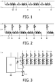
- Fig. 1 shows a schematical diagram of a typical embodiment of a known LED strip. Two strips of conductive material extend along the length of the LED strip. During operation a DC supply voltage of for instance 12 Volts is present between these strips. Series arrangements, each comprising a resistor R and a LED string LS, are connected in parallel between the conductive strips.
- the LED string may comprise one or more LEDs, in the embodiment shown in Fig. 1 three LEDs are comprised in a LED string.
- the conductive strips, the resistors and the LED strings are all mounted on a flexible PCB and covered with a transparent material or a diffusor. A user can cut the LED strip to a desired length at places indicated by a dotted line.
- a disadvantage of the known LED strip is that the electronic circuit of each LED string is not efficient, which also leads to heat development. Furthermore, the LED light output is very sensitive for differences in input voltage.
- US2010/0164409 describes an integrally formed LED light wire with a plurality of conductors and in particular shows a configuration with three continuous conductors.
- the conductors supply power to a plurality of LEDs arrangements, which LED arrangements are positioned between the conductors, parallel to each other.
- resistors are provided in series with the LEDs.
- LED strip may on one hand refer to a flexible mounting member for multiple LEDs and eventually further electrical components, where strips of conductive material extend essentially along its length.
- LED strip is understood to refer to a common mounting member for multiple LEDs, such as in particular a track or rail electrical supply system, i.e. an "LED track", providing electrical connections and/or power to the LEDs.
- a LED light source comprising a first LED strip equipped with
- a LED light source comprises a switch mode power supply for generating a current out of a DC supply voltage, said switch mode power supply comprising
- the first LED strip comprises a series arrangement of a sensor and a resistor coupled in parallel with the series arrangements of a resistor and a LED string comprised in the load and wherein a common terminal of the sensor and the resistor is connected to all the common terminals of the resistors and the LED strings comprised in the load.
- the series arrangement of the sensor and resistor can be positioned anywhere along the LED strip, allowing a user for instance to position the sensor in an optimal place in a room.
- the sensor can be a presence sensor or a light sensor.
- the resistor of at least one of said series arrangements is a controllable resistor/sensor, connected to an associated lamp control device to control the resistance of said resistor.
- the resistor of each of said series arrangements is controllable and connected to an associated lamp control device.
- the present embodiment enables to control the brightness and/or color of the respective series arrangement individually, allowing an enhanced control of the light output of the light source. For example, in case of three series arrangements comprising the colors red, green and blue, it is possible to set the resulting color of the illumination by adjusting the respective "measurement" resistor or sensor.
- a single lamp control device may be present to provide control of all resistors.
- each series arrangement is associated with a "separate" lamp control device to provide a more scalable solution or that some series arrangements share a lamp control device, resulting in a grouped setup.
- the lamp control device may be suitably adapted to control the resistance and thus the current through the respective LED string.
- the lamp control device may comprise a microprocessor with a suitable programming, a user control interface, a brightness sensor and/or a remote control interface to set the resistance of the resistor and thus the brightness of the LED string.
- controllable resistors may be of any suitable type. Certainly, it may be possible that multiple resistors are connected in series to and/or parallel with each other and only the resistance of one or some resistors is controllable.
- the LED light source is a track light source comprising at least one electrical supply track.
- Corresponding track or rail systems are known in the art so that a detailed description is omitted here.
- the supply track or rail may be adapted for a removable engagement with the series arrangement and/or the switch mode power supply.
- the switch mode power supply is formed integrally with the supply track.
- the supply track comprises three separate conductors, connected with said switch mode power supply.
- the series arrangements are comprised in one or more lighting devices, said lighting devices being connectable with said supply track.
- the lighting devices may e.g. comprise a corresponding electrical connector for engagement with the supply track, allowing a simple (re)configuration of the LED light source.
- the lighting devices preferably are formed with a housing in which the LED string(s), the associated resistors and any eventual further components, such as the mentioned diffuser and/or lamp control device, are arranged.
- the lighting devices may thus form "spots", i.e. spot lights.
- Fig. 1 has already been discussed here-above and therefore needs no further description.
- terminals 1 and 3 are input terminals for connection to a DC supply source.
- Input terminals 1 and 3 are connected to each other by means of a plurality of series arrangements, each series arrangement comprising a resistor R and a LED string LS.
- the common terminals of the resistors and the LED strings are all connected to each other and to a terminal 2.
- the reference LS is only added to one of the plurality of LED strings in each Figure.
- switch S, diode D, inductive element L and control circuit CC together form a switch mode power supply.
- the switch mode power supply is powered by a DC supply voltage that is present between terminals 1 and 4.
- Terminal 1 and 3 are output terminals of the switch mode power supply.
- Terminals 1 and 3 are connected by means of a plurality of parallel series arrangements of resistors R and LED strings LS that together form the electronic part of a (first) LED strip.
- the LED strip may for instance further comprise a diffusor.
- Common terminals of resistors R and the LED strings LS are all connected to each other and also to a terminal 2 that is connected to an input terminal of the control circuit CC.
- a series arrangement of inductive element L and switch S connects terminal 3 with terminal 4.
- Diode D connects a common terminal of switch S and inductor L with terminal 1.
- An output terminal of the control circuit CC is connected to a control electrode of the switch S.
- Control circuit CC is further equipped with two input terminals that are connected to terminal 1 and terminal 4 respectively.
- switch S When the magnitude of the currents has reached a first reference value, switch S is made non-conductive by the control circuit CC. During the time lapse in which switch S is non-conductive, current flows from the common terminal of inductive element L and switch S through diode D and through the plurality of series arrangements of a resistor R and a LED string LS to terminal 3. During this time lapse the currents through the LED strings are again substantially the same but now the magnitude of the currents decreases linearly. When the magnitude of the currents has reached a second reference value, the switch S is once more rendered conductive by the control circuit CC. The cycle described here-above is then repeated. In practice the first and second reference value are chosen very close together.
- the switch S is rendered alternately conductive and non-conductive at a high frequency and the current through the LED strings is a DC current with a high frequency AC current superimposed on it. Since the amplitude of the high frequency AC current is very small, the total current can be considered as a DC current with a substantially constant amplitude for most purposes.
- the LED light source shown in Fig. 3 is not very sensitive for changes in the magnitude of the DC-supply voltage and power dissipation in the resistors R is very low so that the LED light source shown in Fig. 3 is very efficient. Another important advantage is that the light output of each LED string is substantially the same and to large extent independent of the amount of LED strings or in other words the length of the LED strip.
- LED strings comprising three LEDs with a forward voltage of 3.2 V carrying a current of 0.02 A were used.
- the power in a LED string is thus 192 mW.
- the resistor was 5 ohm and the power dissipated in the resistor was thus only 2 mW.
- Fig. 4 two embodiments of a LED light source according to the invention are shown comprising a sensor.
- the LED strip comprises a sensor in parallel with the resistors R.
- the sensor is positioned at the end of the LED strip that is opposite to the end where the switch mode power supply is connected.
- the sensor is positioned at an arbitrary position between the resistors R.
- Fig. 4 thus illustrates that the sensor can be positioned anywhere along the LED strip.
- the senor In case the sensor is a light sensor, it acts as a resistor whose resistance is influenced by the amount of light that strikes it. Since the sensor is in parallel to all the resistors R, it influences the amount of current that flows from terminal 1 to terminal 2 and thus the current through each of the resistors R and thus the current through each of the LED strings LS is influenced by the resistance of the sensor.
- the senor is a presence detector, it is a device that has a very low resistance when a presence is detected and a much higher resistance when no presence is detected. As a consequence, the light output of the LED strings is changed from a low light output to a comparatively high light output.
- Fig. 5 thus illustrates that the switch mode power supply can be positioned everywhere along a LED strip.
- the operation of the embodiment shown in Fig. 5 is identical to that shown in Fig. 3 .
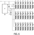
- a LED light source comprising three parallel LED strips and a single switch mode power supply.
- Each of the LED strips is connected to the switch mode power supply in the same way as the single LED strip is in the embodiment shown in Fig. 3 .
- Fig. 6 thus illustrates how a light generating surface can be formed out of LED strips in parallel supplied by the same switch mode power supply.
- the operation of the LED light source is identical to the operation of the embodiment shown in Fig. 3 .
- a LED light source comprising four parallel LED strips and a single switch mode power supply.
- the first LED strip and the second LED strip are so oriented towards each other that the cathodes of the LED strings in the first LED strip are facing the cathodes of the LED strings in the second LED strip.
- the third LED strip and the fourth LED strip are so oriented towards each other that the cathodes of the LED strings in the third LED strip are facing the cathodes of the LED strings in the fourth LED strip.
- the ends opposite to the LED strings of the resistors R comprised in the second and the third LED strip, are facing the corresponding ends of the resistors R in the third LED strip.
Description
- The present invention relates to a LED light source comprising at least one LED strip.
- LED strips are flexible and can be cut to measure and have many indoor and outdoor applications.
Fig. 1 shows a schematical diagram of a typical embodiment of a known LED strip. Two strips of conductive material extend along the length of the LED strip. During operation a DC supply voltage of for instance 12 Volts is present between these strips. Series arrangements, each comprising a resistor R and a LED string LS, are connected in parallel between the conductive strips. The LED string may comprise one or more LEDs, in the embodiment shown inFig. 1 three LEDs are comprised in a LED string. The conductive strips, the resistors and the LED strings are all mounted on a flexible PCB and covered with a transparent material or a diffusor. A user can cut the LED strip to a desired length at places indicated by a dotted line. - A disadvantage of the known LED strip is that the electronic circuit of each LED string is not efficient, which also leads to heat development. Furthermore, the LED light output is very sensitive for differences in input voltage.
-
US2010/0164409 describes an integrally formed LED light wire with a plurality of conductors and in particular shows a configuration with three continuous conductors. The conductors supply power to a plurality of LEDs arrangements, which LED arrangements are positioned between the conductors, parallel to each other. In the LED arrangements, resistors are provided in series with the LEDs. - It is an object of the present invention to provide a light source comprising a LED strip with improved efficiency and a low sensitivity for differences in input voltage, that can also be easily used in combination with presence sensors and/or light sensors. In the present context, the term "LED strip" may on one hand refer to a flexible mounting member for multiple LEDs and eventually further electrical components, where strips of conductive material extend essentially along its length. On the other hand, the term "LED strip" is understood to refer to a common mounting member for multiple LEDs, such as in particular a track or rail electrical supply system, i.e. an "LED track", providing electrical connections and/or power to the LEDs.
- According to an aspect of the present invention a LED light source is provided, comprising a first LED strip equipped with
- input terminals for connection to a DC-supply source,
- a load comprising a plurality of parallel series arrangements connected between the input terminals, wherein each series arrangement comprises a LED string, and a resistor in series and the common terminals of the resistors and the LED strings are all connected to each other.
- Preferably, a LED light source according to the invention comprises a switch mode power supply for generating a current out of a DC supply voltage, said switch mode power supply comprising
- output terminals coupled to the input terminals of the first LED strip,
- a switch,
- a unidirectional element,
- an inductive element,
- a control circuit equipped with an output terminal coupled to the switch for controlling the conductive state of the switch and with an input terminal coupled to the common terminals of the resistors and the LED strings for sensing the current in each of the LED strings. The switch mode power supply is operated as a current source and since the voltage across each resistor is the same, the current through each LED string is substantially equal. Different switch mode power supplies can be used. Good results have been obtained with a switch mode power supply of the type down-converter. The LED light source may comprise at least one further LED strip equipped with
- input terminals connected to the input terminals of the first LED strip,
- a further load comprising a plurality of parallel series arrangements connected between the input terminals, wherein each series arrangement comprises a LED string and a resistor in series and the common terminals of the resistors and the LED strings are all connected to each other and to the input terminal of the control circuit. The first LED strip and the further LED strips are thus supplied by the same switch mode power supply. By arranging the first LED strip and the one or more further LED strips in parallel, a light generating surface can be formed.
- In a preferred embodiment of a light source according to the invention the first LED strip comprises a series arrangement of a sensor and a resistor coupled in parallel with the series arrangements of a resistor and a LED string comprised in the load and wherein a common terminal of the sensor and the resistor is connected to all the common terminals of the resistors and the LED strings comprised in the load. The series arrangement of the sensor and resistor can be positioned anywhere along the LED strip, allowing a user for instance to position the sensor in an optimal place in a room. The sensor can be a presence sensor or a light sensor.
- According to a further preferred embodiment, the resistor of at least one of said series arrangements is a controllable resistor/sensor, connected to an associated lamp control device to control the resistance of said resistor. Preferably, the resistor of each of said series arrangements is controllable and connected to an associated lamp control device.
- The present embodiment enables to control the brightness and/or color of the respective series arrangement individually, allowing an enhanced control of the light output of the light source. For example, in case of three series arrangements comprising the colors red, green and blue, it is possible to set the resulting color of the illumination by adjusting the respective "measurement" resistor or sensor.
- In the above case of more than one series arrangements having controllable resistors, a single lamp control device may be present to provide control of all resistors. Alternatively, it may be feasible that each series arrangement is associated with a "separate" lamp control device to provide a more scalable solution or that some series arrangements share a lamp control device, resulting in a grouped setup.
- The lamp control device may be suitably adapted to control the resistance and thus the current through the respective LED string. The lamp control device may comprise a microprocessor with a suitable programming, a user control interface, a brightness sensor and/or a remote control interface to set the resistance of the resistor and thus the brightness of the LED string.
- The controllable resistors may be of any suitable type. Certainly, it may be possible that multiple resistors are connected in series to and/or parallel with each other and only the resistance of one or some resistors is controllable.
- According to another preferred embodiment, the LED light source is a track light source comprising at least one electrical supply track. Corresponding track or rail systems are known in the art so that a detailed description is omitted here. The supply track or rail may be adapted for a removable engagement with the series arrangement and/or the switch mode power supply. Preferably, the switch mode power supply is formed integrally with the supply track. Most preferably, the supply track comprises three separate conductors, connected with said switch mode power supply.
- Preferably, the series arrangements are comprised in one or more lighting devices, said lighting devices being connectable with said supply track. The lighting devices may e.g. comprise a corresponding electrical connector for engagement with the supply track, allowing a simple (re)configuration of the LED light source. The lighting devices preferably are formed with a housing in which the LED string(s), the associated resistors and any eventual further components, such as the mentioned diffuser and/or lamp control device, are arranged. The lighting devices may thus form "spots", i.e. spot lights.
- Embodiments of a LED light source according to the invention will be further discussed making reference to the enclosed drawings.
- In the drawings,
- Fig. 1
- shows a prior art LED strip, and
- Fig. 2 -7
- show embodiments of LED light sources according to the invention.
-
Fig. 1 has already been discussed here-above and therefore needs no further description. - In
Fig. 2 terminals Input terminals terminal 2. For the sake of clarity the reference LS is only added to one of the plurality of LED strings in each Figure. - In
Fig. 3 , switch S, diode D, inductive element L and control circuit CC together form a switch mode power supply. During operation, the switch mode power supply is powered by a DC supply voltage that is present betweenterminals Terminals terminal 2 that is connected to an input terminal of the control circuit CC. A series arrangement of inductive element L and switch S connects terminal 3 withterminal 4. Diode D connects a common terminal of switch S and inductor L withterminal 1. An output terminal of the control circuit CC is connected to a control electrode of the switch S. Control circuit CC is further equipped with two input terminals that are connected toterminal 1 andterminal 4 respectively. - The operation of the LED light source shown in
Fig. 3 is as follows. - When a DC supply voltage is present between
terminals terminal 1 through the plurality of series arrangements of a resistor R and a LED string LS, and through inductive element L and switch S toterminal 4. As long as switch S is conductive, this current increases linearly. Since all the common terminals of the resistors R and LED strings LS are connected to each other, the voltage drop across each resistor R is the same so that also the magnitude of the current through each resistor is substantially the same. As a consequence the currents through the LED string are also substantially identical.
The control circuit CC senses the magnitude of these currents by sensing the voltage drop across the resistors (i.e. the voltage betweenterminal 1 and terminal 2). When the magnitude of the currents has reached a first reference value, switch S is made non-conductive by the control circuit CC. During the time lapse in which switch S is non-conductive, current flows from the common terminal of inductive element L and switch S through diode D and through the plurality of series arrangements of a resistor R and a LED string LS toterminal 3. During this time lapse the currents through the LED strings are again substantially the same but now the magnitude of the currents decreases linearly. When the magnitude of the currents has reached a second reference value, the switch S is once more rendered conductive by the control circuit CC. The cycle described here-above is then repeated. In practice the first and second reference value are chosen very close together. As a consequence the switch S is rendered alternately conductive and non-conductive at a high frequency and the current through the LED strings is a DC current with a high frequency AC current superimposed on it. Since the amplitude of the high frequency AC current is very small, the total current can be considered as a DC current with a substantially constant amplitude for most purposes. The LED light source shown inFig. 3 is not very sensitive for changes in the magnitude of the DC-supply voltage and power dissipation in the resistors R is very low so that the LED light source shown inFig. 3 is very efficient. Another important advantage is that the light output of each LED string is substantially the same and to large extent independent of the amount of LED strings or in other words the length of the LED strip.
In practical embodiments of the LED light sources inFig. 1 and Fig. 3 LED strings comprising three LEDs with a forward voltage of 3.2 V carrying a current of 0.02 A were used. The power in a LED string is thus 192 mW. The LED light source ofFig. 1 was supplied with a 12V DC supply voltage betweenterminals Fig. 3 , the resistor was 5 ohm and the power dissipated in the resistor was thus only 2 mW. - In
Fig. 4 two embodiments of a LED light source according to the invention are shown comprising a sensor. The only difference between the embodiment shown inFig. 3 and the embodiments shown inFig. 4 , is that in the latter the LED strip comprises a sensor in parallel with the resistors R.
InFig. 4A the sensor is positioned at the end of the LED strip that is opposite to the end where the switch mode power supply is connected. InFig. 4B the sensor is positioned at an arbitrary position between the resistors R.Fig. 4 thus illustrates that the sensor can be positioned anywhere along the LED strip. - In case the sensor is a light sensor, it acts as a resistor whose resistance is influenced by the amount of light that strikes it. Since the sensor is in parallel to all the resistors R, it influences the amount of current that flows from
terminal 1 toterminal 2 and thus the current through each of the resistors R and thus the current through each of the LED strings LS is influenced by the resistance of the sensor. - In case the sensor is a presence detector, it is a device that has a very low resistance when a presence is detected and a much higher resistance when no presence is detected. As a consequence, the light output of the LED strings is changed from a low light output to a comparatively high light output.
- The only difference between the embodiment shown in
Fig. 3 and that shown inFig. 5 is that in the latter the switch mode power supply is positioned at an arbitrary place along the LED strip between the series arrangements of a resistor R and a LED string Ls instead of at one end of the LED strip.Fig. 5 thus illustrates that the switch mode power supply can be positioned everywhere along a LED strip. The operation of the embodiment shown inFig. 5 is identical to that shown inFig. 3 . - In
Fig. 6 an embodiment of a LED light source according to the invention is shown, comprising three parallel LED strips and a single switch mode power supply. Each of the LED strips is connected to the switch mode power supply in the same way as the single LED strip is in the embodiment shown inFig. 3 .Fig. 6 thus illustrates how a light generating surface can be formed out of LED strips in parallel supplied by the same switch mode power supply.
The operation of the LED light source is identical to the operation of the embodiment shown inFig. 3 . - In
Fig. 7 an embodiment of a LED light source according to the invention is shown, comprising four parallel LED strips and a single switch mode power supply. In this embodiment the first LED strip and the second LED strip are so oriented towards each other that the cathodes of the LED strings in the first LED strip are facing the cathodes of the LED strings in the second LED strip.
Similarly, the third LED strip and the fourth LED strip are so oriented towards each other that the cathodes of the LED strings in the third LED strip are facing the cathodes of the LED strings in the fourth LED strip. As a consequence, the ends opposite to the LED strings of the resistors R, comprised in the second and the third LED strip, are facing the corresponding ends of the resistors R in the third LED strip. By connecting the facing cathodes of the LED strings to each other and also connecting the facing ends of the resistors R to each other less wiring is needed to further connect the cathodes of all the LED strings toterminal 3 and the facing ends of the resistors R toterminal 1. The operation of the LED light source shown inFig. 7 is identical to the operation of the embodiment shown inFig. 3 . - The invention has been described in the preceding with reference to the accompanying drawings. It may be however possible to operate the invention in an embodiment, in which
- the resistor of at least one of said series arrangements is controllable and is connected to an associated lamp control device,
- the resistors of each series arrangement is controllable and connected to an associated lamp control device,
- the LED light source is a track light source comprising an electrical supply track and/or
- the series arrangement of LED string and resistor is comprised in a lighting device, said lighting device being removably connected with said electrical supply track, e.g. using a corresponding detachable connector.
Claims (11)
- LED light source comprising a first LED strip equipped with- input terminals (1,3) for connection to a DC-supply source;- a load (LS, R) comprising a plurality of parallel series arrangements;- several conductive paths (1, 2, 3), at least connecting the series arrangements between the input terminals (1, 3);- each series arrangement comprises a LED string (LS) and a resistor (R) in series; the LED light source being characterised in that:- each series arrangement has a common terminal (2) between the LED string (LS) and the resistor (R); and- a sensing conductive path (2) of the several conductive paths (1, 2, 3) connecting the common terminals (2) of each of the series arrangements of the plurality of series arrangements.
- LED light source as claimed in claim 1, comprising a switch mode power supply (CC, D, L, S) for generating a current out of a DC supply voltage, said switch mode power supply comprising- output terminals (1, 3) coupled to the input terminals (1, 3) of the first LED strip,- input terminals (1, 4) coupled to the DC supply voltage- a circuit provided between the input terminals (1, 4) and the output terminals, terminals (1, 3), with a switch (S) and an inductive element (L) in series arrangement, and an unidirectional element (D) adapted to allow the current flow between the output terminals to one direction only, and- a control circuit (CC) equipped with an output terminal coupled to the switch (S) for controlling the conductive state of the switch (S) and with an input terminal coupled by the sensing conductive path (2) to the common terminals of the resistors (R) and the LED strings (LS) for sensing the current in each of the LED strings.
- LED light source as claimed in claim 2, wherein the switch mode power supply (CC, D, L, S) is a down converter.
- LED light source as claimed in claim 1, 2, or 3, wherein the first LED strip comprises a series arrangement of a sensor (Sensor) and a resistor coupled in parallel with all the series arrangements of a resistor (R) and a LED string (LS) comprised in the load and wherein a common terminal of the sensor and the resistor is connected to all the common terminals (2) of the resistors (R) and the LED strings (LS) comprised in the load.
- LED light source as claimed in claim 4, wherein the sensor (Sensor) is a presence sensor.
- LED light source as claimed in claim 4, wherein the sensor (Sensor) is a light sensor.
- LED light source as claimed in claim 2, wherein the LED light source comprises at least one further LED strip (LS) equipped with- input terminals (1,3) connected to the input terminals (1, 3) of the first LED strip (LS),- a further load comprising a plurality of parallel series arrangements connected between the input terminals, wherein each series arrangement comprises a LED string (LS) and a resistor (R) in series and the common terminals (2) of the resistors (R) and the LED strings (LS) are all connected to each other and to the input terminal of the control circuit (CC).
- LED light source according to one of the preceding claims, wherein the resistor (R) of at least one of said series arrangements is a controllable resistor, connected to at least one associated lamp control device to control the resistance of said resistor.
- LED light source according to claim 8, wherein the resistor (R) of each series arrangement is controllable and is connected to said at least one lamp control device.
- LED light source according to one of the preceding claims, wherein the LED light source is a track light source comprising an electrical supply track.
- LED light source according to claim 10, wherein the series arrangement of LED string (LS) and resistor (R) is comprised in a lighting device, said lighting device being removable connectable with said electrical supply track.
Applications Claiming Priority (2)
| Application Number | Priority Date | Filing Date | Title |
|---|---|---|---|
| US201161509622P | 2011-07-20 | 2011-07-20 | |
| PCT/IB2012/053536 WO2013011422A1 (en) | 2011-07-20 | 2012-07-11 | Light source comprising a led strip |
Publications (2)
| Publication Number | Publication Date |
|---|---|
| EP2735211A1 EP2735211A1 (en) | 2014-05-28 |
| EP2735211B1 true EP2735211B1 (en) | 2018-04-18 |
Family
ID=46888496
Family Applications (1)
| Application Number | Title | Priority Date | Filing Date |
|---|---|---|---|
| EP12762045.8A Active EP2735211B1 (en) | 2011-07-20 | 2012-07-11 | Light source comprising a led strip |
Country Status (8)
| Country | Link |
|---|---|
| US (1) | US9119255B2 (en) |
| EP (1) | EP2735211B1 (en) |
| JP (1) | JP6067697B2 (en) |
| CN (1) | CN103688592B (en) |
| BR (1) | BR112014001014A2 (en) |
| IN (1) | IN2014CN00670A (en) |
| RU (1) | RU2594293C2 (en) |
| WO (1) | WO2013011422A1 (en) |
Families Citing this family (9)
| Publication number | Priority date | Publication date | Assignee | Title |
|---|---|---|---|---|
| DE202013000064U1 (en) * | 2013-01-04 | 2013-01-18 | Osram Gmbh | LED array |
| US9554436B2 (en) | 2013-07-24 | 2017-01-24 | Philips Lighting Holding B.V. | Power supply for LED lighting system |
| PL222678B1 (en) | 2013-08-23 | 2016-08-31 | Włodarczyk Władysław Igloo | Three phase power supply and the LED diode system with three phase power supply |
| US9772076B2 (en) * | 2013-09-30 | 2017-09-26 | Osram Sylvania Inc. | Cuttable flexible light engines |
| US9516710B1 (en) * | 2015-06-25 | 2016-12-06 | Salcomp Taiwan Co., Ltd | Light emitting diode driving device with control based on LED setting resistance |
| US9723670B2 (en) | 2015-06-25 | 2017-08-01 | Salcomp Taiwan Co., Ltd. | Power supply device with control based on setting resistor |
| DE102020001001A1 (en) * | 2020-02-17 | 2021-08-19 | LS Lighting Solutions GmbH | LED strips |
| DE102020203041A1 (en) | 2020-03-10 | 2021-09-16 | Osram Gmbh | LIGHTING A TEXTILE |
| US11097173B1 (en) * | 2020-07-09 | 2021-08-24 | Louis Celenza, Jr. | Light source illuminating the rim, net and backboard of a basketball system |
Family Cites Families (27)
| Publication number | Priority date | Publication date | Assignee | Title |
|---|---|---|---|---|
| WO1996019093A1 (en) | 1994-12-14 | 1996-06-20 | Luminescent Systems, Inc. | Led light strip with brightness/current draw control circuitry |
| US6095661A (en) * | 1998-03-19 | 2000-08-01 | Ppt Vision, Inc. | Method and apparatus for an L.E.D. flashlight |
| US7740371B1 (en) * | 1998-03-19 | 2010-06-22 | Charles A. Lemaire | Method and apparatus for pulsed L.E.D. illumination for a camera |
| RU2151473C1 (en) * | 1998-06-25 | 2000-06-20 | АОЗТ "Электролуч" | Device for connection of led-equipped illumination device into alternating current supply line |
| US8063575B2 (en) | 2002-07-04 | 2011-11-22 | Tridonic Jennersdorf Gmbh | Current supply for luminescent diodes |
| JP4236894B2 (en) * | 2002-10-08 | 2009-03-11 | 株式会社小糸製作所 | Lighting circuit |
| US7258463B2 (en) * | 2003-05-19 | 2007-08-21 | Sloanled, Inc. | Multiple LED control apparatus and method |
| DE10324609B4 (en) * | 2003-05-30 | 2014-11-13 | Osram Gmbh | Control circuit and LED array and method for operating an LED array |
| US20060221609A1 (en) | 2003-06-12 | 2006-10-05 | Ryan Patrick H Jr | Lighting strip |
| JP4262565B2 (en) * | 2003-10-15 | 2009-05-13 | 株式会社松村電機製作所 | Lighting device |
| US6914194B2 (en) | 2003-10-29 | 2005-07-05 | Ben Fan | Flexible LED cable light |
| AU2005216335B2 (en) * | 2004-02-25 | 2011-03-31 | James N. Andersen | AC light emitting diode and AC LED drive methods and apparatus |
| WO2006017930A1 (en) | 2004-08-18 | 2006-02-23 | Remco Solid State Lighting Inc. | Led control utilizing dynamic resistance of leds |
| US7411174B2 (en) | 2004-10-12 | 2008-08-12 | Eash Brandon A | Sensor-controlled LED array apparatus and method |
| US7821212B2 (en) | 2005-04-12 | 2010-10-26 | J & J Electronics, Inc. | Networkable controllers for LED lighting |
| US7847783B2 (en) | 2005-10-11 | 2010-12-07 | O2Micro International Limited | Controller circuitry for light emitting diodes |
| US7524079B2 (en) * | 2006-06-23 | 2009-04-28 | William John Greenhoe | Solar rechargeable lantern |
| US8567992B2 (en) * | 2006-09-12 | 2013-10-29 | Huizhou Light Engine Ltd. | Integrally formed light emitting diode light wire and uses thereof |
| US7766508B2 (en) | 2006-09-12 | 2010-08-03 | Cree, Inc. | LED lighting fixture |
| US7988332B2 (en) * | 2006-09-12 | 2011-08-02 | Huizhou Light Engine Ltd. | Integrally formed single piece light emitting diode light wire |
| US7851981B2 (en) * | 2006-12-22 | 2010-12-14 | Seasonal Specialties, Llc | Visible perception of brightness in miniature bulbs for an ornamental lighting circuit |
| US8410720B2 (en) * | 2008-04-07 | 2013-04-02 | Metrospec Technology, LLC. | Solid state lighting circuit and controls |
| RU2497316C2 (en) * | 2008-05-06 | 2013-10-27 | Конинклейке Филипс Электроникс Н.В. | Led excitation device |
| US8242704B2 (en) * | 2008-09-09 | 2012-08-14 | Point Somee Limited Liability Company | Apparatus, method and system for providing power to solid state lighting |
| CN201555060U (en) | 2009-08-11 | 2010-08-18 | 汤征宁 | LED strip light with length capable of being combined according to needs |
| US8299724B2 (en) * | 2010-03-19 | 2012-10-30 | Active-Semi, Inc. | AC LED lamp involving an LED string having separately shortable sections |
| US20130200790A1 (en) * | 2011-10-21 | 2013-08-08 | Almax Rp, Corp. | Arrays of light sources energized with branched and looped electrodes for signage |
-
2012
- 2012-07-11 US US14/233,775 patent/US9119255B2/en active Active
- 2012-07-11 EP EP12762045.8A patent/EP2735211B1/en active Active
- 2012-07-11 RU RU2014106292/07A patent/RU2594293C2/en active
- 2012-07-11 CN CN201280035741.2A patent/CN103688592B/en active Active
- 2012-07-11 BR BR112014001014A patent/BR112014001014A2/en not_active IP Right Cessation
- 2012-07-11 JP JP2014520757A patent/JP6067697B2/en active Active
- 2012-07-11 IN IN670CHN2014 patent/IN2014CN00670A/en unknown
- 2012-07-11 WO PCT/IB2012/053536 patent/WO2013011422A1/en active Application Filing
Non-Patent Citations (1)
| Title |
|---|
| None * |
Also Published As
| Publication number | Publication date |
|---|---|
| BR112014001014A2 (en) | 2017-02-21 |
| EP2735211A1 (en) | 2014-05-28 |
| IN2014CN00670A (en) | 2015-04-03 |
| JP2014525145A (en) | 2014-09-25 |
| JP6067697B2 (en) | 2017-01-25 |
| RU2014106292A (en) | 2015-08-27 |
| RU2594293C2 (en) | 2016-08-10 |
| CN103688592A (en) | 2014-03-26 |
| US20140167632A1 (en) | 2014-06-19 |
| WO2013011422A1 (en) | 2013-01-24 |
| US9119255B2 (en) | 2015-08-25 |
| CN103688592B (en) | 2016-11-02 |
Similar Documents
| Publication | Publication Date | Title |
|---|---|---|
| EP2735211B1 (en) | Light source comprising a led strip | |
| US9730282B2 (en) | Switchable luminance LED light bulb | |
| TWI811305B (en) | Integrated light emitting diode (led) lighting systems and methods for operating an led driver circuit | |
| JP5725736B2 (en) | LED power supply device and LED lighting apparatus | |
| US20040004446A1 (en) | Drive circuit for an led lighting apparatus | |
| US20210156532A1 (en) | Encapsulated led strip without a power supply | |
| US7750576B2 (en) | Light string with external resistor unit | |
| JP2014525145A5 (en) | ||
| JP6489473B2 (en) | Power supply device and lighting device | |
| JP4187565B2 (en) | Lighting device | |
| US10928046B2 (en) | Light board for lighting fixture | |
| JP6489523B2 (en) | Solid state light emitting device module and lighting set | |
| JP2015018780A (en) | Lighting device and illumination device | |
| CN108307557A (en) | Method and apparatus for correcting electric harmonic | |
| JP6566354B2 (en) | Dimming control device, lighting system, and equipment | |
| JP6249334B2 (en) | Lighting device and lighting fixture including the lighting device | |
| CN108093513B (en) | A kind of method and brightness switching device of control LED lamp brightness switching | |
| JP2016149261A (en) | Light source unit and illuminating fixture using the same | |
| CN111432521A (en) | Induction splicing lamp | |
| WO2017016253A1 (en) | Led lighting combination set | |
| JP6489472B2 (en) | Power supply device and lighting device | |
| US20170019962A1 (en) | LED Circuit With Multiple Switch Configurations | |
| US20150316243A1 (en) | Driver Circuit Integrated LED Module | |
| CN211959613U (en) | Induction splicing lamp | |
| TWI450639B (en) | Methods and apparatus for driving led-based lighting units |
Legal Events
| Date | Code | Title | Description |
|---|---|---|---|
| PUAI | Public reference made under article 153(3) epc to a published international application that has entered the european phase |
Free format text: ORIGINAL CODE: 0009012 |
|
| 17P | Request for examination filed |
Effective date: 20140220 |
|
| AK | Designated contracting states |
Kind code of ref document: A1 Designated state(s): AL AT BE BG CH CY CZ DE DK EE ES FI FR GB GR HR HU IE IS IT LI LT LU LV MC MK MT NL NO PL PT RO RS SE SI SK SM TR |
|
| DAX | Request for extension of the european patent (deleted) | ||
| RAP1 | Party data changed (applicant data changed or rights of an application transferred) |
Owner name: PHILIPS LIGHTING HOLDING B.V. |
|
| RIN1 | Information on inventor provided before grant (corrected) |
Inventor name: VAN DEN BIGGELAAR, THEODORUS JOHANNES PETRUS Inventor name: PIJLMAN, FETZE |
|
| GRAP | Despatch of communication of intention to grant a patent |
Free format text: ORIGINAL CODE: EPIDOSNIGR1 |
|
| INTG | Intention to grant announced |
Effective date: 20171116 |
|
| GRAS | Grant fee paid |
Free format text: ORIGINAL CODE: EPIDOSNIGR3 |
|
| GRAA | (expected) grant |
Free format text: ORIGINAL CODE: 0009210 |
|
| AK | Designated contracting states |
Kind code of ref document: B1 Designated state(s): AL AT BE BG CH CY CZ DE DK EE ES FI FR GB GR HR HU IE IS IT LI LT LU LV MC MK MT NL NO PL PT RO RS SE SI SK SM TR |
|
| REG | Reference to a national code |
Ref country code: GB Ref legal event code: FG4D |
|
| REG | Reference to a national code |
Ref country code: CH Ref legal event code: EP |
|
| REG | Reference to a national code |
Ref country code: AT Ref legal event code: REF Ref document number: 991789 Country of ref document: AT Kind code of ref document: T Effective date: 20180515 |
|
| REG | Reference to a national code |
Ref country code: IE Ref legal event code: FG4D |
|
| REG | Reference to a national code |
Ref country code: DE Ref legal event code: R096 Ref document number: 602012045353 Country of ref document: DE |
|
| REG | Reference to a national code |
Ref country code: FR Ref legal event code: PLFP Year of fee payment: 7 |
|
| REG | Reference to a national code |
Ref country code: NL Ref legal event code: MP Effective date: 20180418 |
|
| REG | Reference to a national code |
Ref country code: LT Ref legal event code: MG4D |
|
| PG25 | Lapsed in a contracting state [announced via postgrant information from national office to epo] |
Ref country code: NL Free format text: LAPSE BECAUSE OF FAILURE TO SUBMIT A TRANSLATION OF THE DESCRIPTION OR TO PAY THE FEE WITHIN THE PRESCRIBED TIME-LIMIT Effective date: 20180418 |
|
| PG25 | Lapsed in a contracting state [announced via postgrant information from national office to epo] |
Ref country code: FI Free format text: LAPSE BECAUSE OF FAILURE TO SUBMIT A TRANSLATION OF THE DESCRIPTION OR TO PAY THE FEE WITHIN THE PRESCRIBED TIME-LIMIT Effective date: 20180418 Ref country code: NO Free format text: LAPSE BECAUSE OF FAILURE TO SUBMIT A TRANSLATION OF THE DESCRIPTION OR TO PAY THE FEE WITHIN THE PRESCRIBED TIME-LIMIT Effective date: 20180718 Ref country code: BG Free format text: LAPSE BECAUSE OF FAILURE TO SUBMIT A TRANSLATION OF THE DESCRIPTION OR TO PAY THE FEE WITHIN THE PRESCRIBED TIME-LIMIT Effective date: 20180718 Ref country code: PL Free format text: LAPSE BECAUSE OF FAILURE TO SUBMIT A TRANSLATION OF THE DESCRIPTION OR TO PAY THE FEE WITHIN THE PRESCRIBED TIME-LIMIT Effective date: 20180418 Ref country code: SE Free format text: LAPSE BECAUSE OF FAILURE TO SUBMIT A TRANSLATION OF THE DESCRIPTION OR TO PAY THE FEE WITHIN THE PRESCRIBED TIME-LIMIT Effective date: 20180418 Ref country code: AL Free format text: LAPSE BECAUSE OF FAILURE TO SUBMIT A TRANSLATION OF THE DESCRIPTION OR TO PAY THE FEE WITHIN THE PRESCRIBED TIME-LIMIT Effective date: 20180418 Ref country code: ES Free format text: LAPSE BECAUSE OF FAILURE TO SUBMIT A TRANSLATION OF THE DESCRIPTION OR TO PAY THE FEE WITHIN THE PRESCRIBED TIME-LIMIT Effective date: 20180418 Ref country code: LT Free format text: LAPSE BECAUSE OF FAILURE TO SUBMIT A TRANSLATION OF THE DESCRIPTION OR TO PAY THE FEE WITHIN THE PRESCRIBED TIME-LIMIT Effective date: 20180418 |
|
| PG25 | Lapsed in a contracting state [announced via postgrant information from national office to epo] |
Ref country code: LV Free format text: LAPSE BECAUSE OF FAILURE TO SUBMIT A TRANSLATION OF THE DESCRIPTION OR TO PAY THE FEE WITHIN THE PRESCRIBED TIME-LIMIT Effective date: 20180418 Ref country code: HR Free format text: LAPSE BECAUSE OF FAILURE TO SUBMIT A TRANSLATION OF THE DESCRIPTION OR TO PAY THE FEE WITHIN THE PRESCRIBED TIME-LIMIT Effective date: 20180418 Ref country code: GR Free format text: LAPSE BECAUSE OF FAILURE TO SUBMIT A TRANSLATION OF THE DESCRIPTION OR TO PAY THE FEE WITHIN THE PRESCRIBED TIME-LIMIT Effective date: 20180719 Ref country code: RS Free format text: LAPSE BECAUSE OF FAILURE TO SUBMIT A TRANSLATION OF THE DESCRIPTION OR TO PAY THE FEE WITHIN THE PRESCRIBED TIME-LIMIT Effective date: 20180418 |
|
| RAP2 | Party data changed (patent owner data changed or rights of a patent transferred) |
Owner name: PHILIPS LIGHTING HOLDING B.V. |
|
| REG | Reference to a national code |
Ref country code: AT Ref legal event code: MK05 Ref document number: 991789 Country of ref document: AT Kind code of ref document: T Effective date: 20180418 |
|
| PG25 | Lapsed in a contracting state [announced via postgrant information from national office to epo] |
Ref country code: PT Free format text: LAPSE BECAUSE OF FAILURE TO SUBMIT A TRANSLATION OF THE DESCRIPTION OR TO PAY THE FEE WITHIN THE PRESCRIBED TIME-LIMIT Effective date: 20180820 |
|
| REG | Reference to a national code |
Ref country code: DE Ref legal event code: R097 Ref document number: 602012045353 Country of ref document: DE |
|
| PG25 | Lapsed in a contracting state [announced via postgrant information from national office to epo] |
Ref country code: DK Free format text: LAPSE BECAUSE OF FAILURE TO SUBMIT A TRANSLATION OF THE DESCRIPTION OR TO PAY THE FEE WITHIN THE PRESCRIBED TIME-LIMIT Effective date: 20180418 Ref country code: EE Free format text: LAPSE BECAUSE OF FAILURE TO SUBMIT A TRANSLATION OF THE DESCRIPTION OR TO PAY THE FEE WITHIN THE PRESCRIBED TIME-LIMIT Effective date: 20180418 Ref country code: AT Free format text: LAPSE BECAUSE OF FAILURE TO SUBMIT A TRANSLATION OF THE DESCRIPTION OR TO PAY THE FEE WITHIN THE PRESCRIBED TIME-LIMIT Effective date: 20180418 Ref country code: CZ Free format text: LAPSE BECAUSE OF FAILURE TO SUBMIT A TRANSLATION OF THE DESCRIPTION OR TO PAY THE FEE WITHIN THE PRESCRIBED TIME-LIMIT Effective date: 20180418 Ref country code: RO Free format text: LAPSE BECAUSE OF FAILURE TO SUBMIT A TRANSLATION OF THE DESCRIPTION OR TO PAY THE FEE WITHIN THE PRESCRIBED TIME-LIMIT Effective date: 20180418 Ref country code: SK Free format text: LAPSE BECAUSE OF FAILURE TO SUBMIT A TRANSLATION OF THE DESCRIPTION OR TO PAY THE FEE WITHIN THE PRESCRIBED TIME-LIMIT Effective date: 20180418 |
|
| PLBE | No opposition filed within time limit |
Free format text: ORIGINAL CODE: 0009261 |
|
| STAA | Information on the status of an ep patent application or granted ep patent |
Free format text: STATUS: NO OPPOSITION FILED WITHIN TIME LIMIT |
|
| PG25 | Lapsed in a contracting state [announced via postgrant information from national office to epo] |
Ref country code: SM Free format text: LAPSE BECAUSE OF FAILURE TO SUBMIT A TRANSLATION OF THE DESCRIPTION OR TO PAY THE FEE WITHIN THE PRESCRIBED TIME-LIMIT Effective date: 20180418 Ref country code: IT Free format text: LAPSE BECAUSE OF FAILURE TO SUBMIT A TRANSLATION OF THE DESCRIPTION OR TO PAY THE FEE WITHIN THE PRESCRIBED TIME-LIMIT Effective date: 20180418 |
|
| REG | Reference to a national code |
Ref country code: CH Ref legal event code: PL |
|
| RAP2 | Party data changed (patent owner data changed or rights of a patent transferred) |
Owner name: SIGNIFY HOLDING B.V. |
|
| 26N | No opposition filed |
Effective date: 20190121 |
|
| PG25 | Lapsed in a contracting state [announced via postgrant information from national office to epo] |
Ref country code: MC Free format text: LAPSE BECAUSE OF FAILURE TO SUBMIT A TRANSLATION OF THE DESCRIPTION OR TO PAY THE FEE WITHIN THE PRESCRIBED TIME-LIMIT Effective date: 20180418 Ref country code: LU Free format text: LAPSE BECAUSE OF NON-PAYMENT OF DUE FEES Effective date: 20180711 |
|
| REG | Reference to a national code |
Ref country code: BE Ref legal event code: MM Effective date: 20180731 |
|
| REG | Reference to a national code |
Ref country code: IE Ref legal event code: MM4A |
|
| PG25 | Lapsed in a contracting state [announced via postgrant information from national office to epo] |
Ref country code: IE Free format text: LAPSE BECAUSE OF NON-PAYMENT OF DUE FEES Effective date: 20180711 Ref country code: LI Free format text: LAPSE BECAUSE OF NON-PAYMENT OF DUE FEES Effective date: 20180731 Ref country code: CH Free format text: LAPSE BECAUSE OF NON-PAYMENT OF DUE FEES Effective date: 20180731 |
|
| PG25 | Lapsed in a contracting state [announced via postgrant information from national office to epo] |
Ref country code: SI Free format text: LAPSE BECAUSE OF FAILURE TO SUBMIT A TRANSLATION OF THE DESCRIPTION OR TO PAY THE FEE WITHIN THE PRESCRIBED TIME-LIMIT Effective date: 20180418 Ref country code: BE Free format text: LAPSE BECAUSE OF NON-PAYMENT OF DUE FEES Effective date: 20180731 |
|
| REG | Reference to a national code |
Ref country code: DE Ref legal event code: R079 Ref document number: 602012045353 Country of ref document: DE Free format text: PREVIOUS MAIN CLASS: H05B0033080000 Ipc: H05B0045000000 |
|
| PG25 | Lapsed in a contracting state [announced via postgrant information from national office to epo] |
Ref country code: MT Free format text: LAPSE BECAUSE OF NON-PAYMENT OF DUE FEES Effective date: 20180711 |
|
| PG25 | Lapsed in a contracting state [announced via postgrant information from national office to epo] |
Ref country code: TR Free format text: LAPSE BECAUSE OF FAILURE TO SUBMIT A TRANSLATION OF THE DESCRIPTION OR TO PAY THE FEE WITHIN THE PRESCRIBED TIME-LIMIT Effective date: 20180418 |
|
| PG25 | Lapsed in a contracting state [announced via postgrant information from national office to epo] |
Ref country code: HU Free format text: LAPSE BECAUSE OF FAILURE TO SUBMIT A TRANSLATION OF THE DESCRIPTION OR TO PAY THE FEE WITHIN THE PRESCRIBED TIME-LIMIT; INVALID AB INITIO Effective date: 20120711 |
|
| PG25 | Lapsed in a contracting state [announced via postgrant information from national office to epo] |
Ref country code: CY Free format text: LAPSE BECAUSE OF FAILURE TO SUBMIT A TRANSLATION OF THE DESCRIPTION OR TO PAY THE FEE WITHIN THE PRESCRIBED TIME-LIMIT Effective date: 20180418 Ref country code: MK Free format text: LAPSE BECAUSE OF NON-PAYMENT OF DUE FEES Effective date: 20180418 |
|
| PG25 | Lapsed in a contracting state [announced via postgrant information from national office to epo] |
Ref country code: IS Free format text: LAPSE BECAUSE OF FAILURE TO SUBMIT A TRANSLATION OF THE DESCRIPTION OR TO PAY THE FEE WITHIN THE PRESCRIBED TIME-LIMIT Effective date: 20180818 |
|
| REG | Reference to a national code |
Ref country code: DE Ref legal event code: R081 Ref document number: 602012045353 Country of ref document: DE Owner name: SIGNIFY HOLDING B.V., NL Free format text: FORMER OWNER: PHILIPS LIGHTING HOLDING B.V., EINDHOVEN, NL |
|
| P01 | Opt-out of the competence of the unified patent court (upc) registered |
Effective date: 20230421 |
|
| PGFP | Annual fee paid to national office [announced via postgrant information from national office to epo] |
Ref country code: GB Payment date: 20230725 Year of fee payment: 12 |
|
| PGFP | Annual fee paid to national office [announced via postgrant information from national office to epo] |
Ref country code: FR Payment date: 20230725 Year of fee payment: 12 Ref country code: DE Payment date: 20230928 Year of fee payment: 12 |