EP2735001B1 - Environmentally robust electromagnets and electric motors employing same for use in nuclear reactors - Google Patents
Environmentally robust electromagnets and electric motors employing same for use in nuclear reactors Download PDFInfo
- Publication number
- EP2735001B1 EP2735001B1 EP12817197.2A EP12817197A EP2735001B1 EP 2735001 B1 EP2735001 B1 EP 2735001B1 EP 12817197 A EP12817197 A EP 12817197A EP 2735001 B1 EP2735001 B1 EP 2735001B1
- Authority
- EP
- European Patent Office
- Prior art keywords
- electrically insulating
- freestanding
- insulating former
- layer
- helical
- Prior art date
- Legal status (The legal status is an assumption and is not a legal conclusion. Google has not performed a legal analysis and makes no representation as to the accuracy of the status listed.)
- Active
Links
Images






Classifications
-
- H—ELECTRICITY
- H02—GENERATION; CONVERSION OR DISTRIBUTION OF ELECTRIC POWER
- H02K—DYNAMO-ELECTRIC MACHINES
- H02K3/00—Details of windings
- H02K3/04—Windings characterised by the conductor shape, form or construction, e.g. with bar conductors
- H02K3/18—Windings for salient poles
-
- G—PHYSICS
- G21—NUCLEAR PHYSICS; NUCLEAR ENGINEERING
- G21C—NUCLEAR REACTORS
- G21C15/00—Cooling arrangements within the pressure vessel containing the core; Selection of specific coolants
- G21C15/24—Promoting flow of the coolant
-
- G—PHYSICS
- G21—NUCLEAR PHYSICS; NUCLEAR ENGINEERING
- G21C—NUCLEAR REACTORS
- G21C7/00—Control of nuclear reaction
- G21C7/06—Control of nuclear reaction by application of neutron-absorbing material, i.e. material with absorption cross-section very much in excess of reflection cross-section
- G21C7/08—Control of nuclear reaction by application of neutron-absorbing material, i.e. material with absorption cross-section very much in excess of reflection cross-section by displacement of solid control elements, e.g. control rods
- G21C7/12—Means for moving control elements to desired position
-
- H—ELECTRICITY
- H01—ELECTRIC ELEMENTS
- H01F—MAGNETS; INDUCTANCES; TRANSFORMERS; SELECTION OF MATERIALS FOR THEIR MAGNETIC PROPERTIES
- H01F5/00—Coils
- H01F5/02—Coils wound on non-magnetic supports, e.g. formers
-
- H—ELECTRICITY
- H02—GENERATION; CONVERSION OR DISTRIBUTION OF ELECTRIC POWER
- H02K—DYNAMO-ELECTRIC MACHINES
- H02K3/00—Details of windings
- H02K3/46—Fastening of windings on the stator or rotor structure
- H02K3/52—Fastening salient pole windings or connections thereto
- H02K3/521—Fastening salient pole windings or connections thereto applicable to stators only
- H02K3/522—Fastening salient pole windings or connections thereto applicable to stators only for generally annular cores with salient poles
-
- H—ELECTRICITY
- H01—ELECTRIC ELEMENTS
- H01F—MAGNETS; INDUCTANCES; TRANSFORMERS; SELECTION OF MATERIALS FOR THEIR MAGNETIC PROPERTIES
- H01F5/00—Coils
- H01F5/02—Coils wound on non-magnetic supports, e.g. formers
- H01F2005/025—Coils wound on non-magnetic supports, e.g. formers wound on coaxial arrangement of two or more formers
-
- H—ELECTRICITY
- H02—GENERATION; CONVERSION OR DISTRIBUTION OF ELECTRIC POWER
- H02K—DYNAMO-ELECTRIC MACHINES
- H02K2203/00—Specific aspects not provided for in the other groups of this subclass relating to the windings
- H02K2203/12—Machines characterised by the bobbins for supporting the windings
-
- Y—GENERAL TAGGING OF NEW TECHNOLOGICAL DEVELOPMENTS; GENERAL TAGGING OF CROSS-SECTIONAL TECHNOLOGIES SPANNING OVER SEVERAL SECTIONS OF THE IPC; TECHNICAL SUBJECTS COVERED BY FORMER USPC CROSS-REFERENCE ART COLLECTIONS [XRACs] AND DIGESTS
- Y02—TECHNOLOGIES OR APPLICATIONS FOR MITIGATION OR ADAPTATION AGAINST CLIMATE CHANGE
- Y02E—REDUCTION OF GREENHOUSE GAS [GHG] EMISSIONS, RELATED TO ENERGY GENERATION, TRANSMISSION OR DISTRIBUTION
- Y02E30/00—Energy generation of nuclear origin
- Y02E30/30—Nuclear fission reactors
-
- Y—GENERAL TAGGING OF NEW TECHNOLOGICAL DEVELOPMENTS; GENERAL TAGGING OF CROSS-SECTIONAL TECHNOLOGIES SPANNING OVER SEVERAL SECTIONS OF THE IPC; TECHNICAL SUBJECTS COVERED BY FORMER USPC CROSS-REFERENCE ART COLLECTIONS [XRACs] AND DIGESTS
- Y10—TECHNICAL SUBJECTS COVERED BY FORMER USPC
- Y10T—TECHNICAL SUBJECTS COVERED BY FORMER US CLASSIFICATION
- Y10T29/00—Metal working
- Y10T29/49—Method of mechanical manufacture
- Y10T29/49002—Electrical device making
- Y10T29/4902—Electromagnet, transformer or inductor
- Y10T29/49071—Electromagnet, transformer or inductor by winding or coiling
Definitions
- the following relates to the electrical arts, electrical device arts, electromagnet arts, electric motor arts, nuclear reactor arts, and related arts.
- a pressurized water reactor employs a pressure vessel containing superheated water as the primary coolant. Hot, subcooled water is circulated between the reactor core and one or more steam generators to transfer energy from the reactor core to the steam generator.
- the steam generators are separate elements and the primary coolant is coupled between the pressure vessel and the steam generator via suitable high pressure fluid conduits.
- the one or more steam generators are located inside the pressure vessel.
- Other types of nuclear reactors are similar.
- a boiling water reactor employs boiling primary coolant which is not superheated.
- the primary coolant is actively circulated using electric motor-driven coolant pumps.
- the pumps may be located outside the pressure vessel and mechanically coupled with the impeller via a rotating shaft passing through a suitable vessel penetration.
- it is advantageous to eliminate the mechanical pass-through vessel penetration by employing wholly internal motor-driven coolant pumps. In this latter design, only small and mechanically static vessel penetrations for electrical cabling are employed.
- control rod drive mechanism CRDM
- a control rod containing a neutron absorber is inserted partway or fully into the reactor core in order to moderate or stop the nuclear reaction.
- the extent of the rod insertion is adjustable in a continuous or step-wise fashion in order to provide adjustable reactivity control.
- the electric motor operating the control rod is located outside the pressure vessel (typically above the pressure vessel in PWR designs or below the pressure vessel in BWR designs) and a connecting rod passes through a suitable vessel penetration to connect the CRDM motor with the control rod.
- the invention may take form in various components and arrangements of components, and in various process operations and arrangements of process operations.
- the drawings are only for purposes of illustrating preferred embodiments and are not to be construed as limiting the invention.
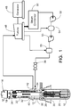
- FIGURE 1 a perspective sectional view an illustrative pressurized water nuclear reactor (PWR) including an integral steam generator is shown.
- a nuclear reactor core 10 is disposed inside a generally cylindrical pressure vessel 12, which contains primary coolant 14, which in the illustrative case of a light water reactor is water (H 2 O) optionally containing additives such as soluble boric acid serving as a soluble neutron poison.
- the PWR includes a steam bubble 16 in the upper portion of the volume, with a water level 18 delineating between the steam bubble 16 and the liquid primary coolant 14. Pressure is adjusted via the steam bubble 16, using electric heaters or the like or an external pressurizer (components not shown).
- a control rod drive mechanism (CRDM) 20 that is configured to controllably insert and withdraw neutron-absorbing control rods into and out of the nuclear reactor core 10.
- the CRDM 20 may be divided into multiple units, each controlling one or more control rods, in order to provide redundancy or other benefits.
- the illustrative CRDM 20 is an internal system in which the drive motors and other components are disposed inside the pressure vessel 12 and submerged in the primary coolant 14, with only electrical power and control wiring extending outside the pressure vessel 12. Alternatively, external CRDM may be employed.
- the pressure vessel 12 is configured to define a desired circulation of the primary coolant 14.
- the circulation is defined by a hollow cylindrical central riser 22 disposed coaxially in the illustrative cylindrical pressure vessel 12.
- Primary coolant 14 heated by the reactor core 10 flows upward through fluid conduits passing through the internal CRDM 20 and upward through the hollow central riser 22, discharges at the top of the hollow central riser 22 and is diverted downward by a diverter 24, flows downward through an annulus defined between the cylindrical central riser 22 and the walls of the cylindrical pressure vessel 12, and is then diverted upward at the bottom of the pressure vessel 12 to return to the reactor core 10.
- Optional primary coolant pumps 26 may be provided to drive the circulation of the primary coolant 14, or to assist natural circulation of the primary coolant 14.
- the illustrative coolant pumps 26 are internal pumps which are wholly inside the pressure vessel 12 and submerged in the primary coolant 14, with only electrical power and optional control wiring extending outside the pressure vessel 12. Alternatively, natural circulation may be relied upon for circulating the primary coolant.
- the pressure vessel 12 is suitably positioned substantially vertically.
- An optional skirt 30 may be provided to support the pressure vessel 12, or to bias against the pressure vessel 12 tipping over.
- the illustrative skirt 30 is positioned such that the lower portion of the pressure vessel 12 containing the reactor core 10 is located in a recess below ground, which facilitates flooding for safety in the event of a loss of coolant accident (LOCA) or other accident.
- LOCA loss of coolant accident
- the CRDM 20 withdraws (or at least partially withdraws) the control rods from the nuclear reactor core 10 to initiate a nuclear reaction in the core 10.
- the primary coolant 14 serves as a neutron moderator to thermalize higher energy neutrons so as to maintain or enhance the nuclear reaction.
- the primary coolant 14 is superheated and is at a temperature of typically at least 300°C, and in some embodiments is at a temperature of at least 350°C.
- the primary coolant is not superheated but is boiling, and the boiling primary coolant is typically at a temperature of at least at 300°C and in some embodiments at least 350°C.
- the primary coolant 14 heated by the operating reactor core 10 is brought into thermal communication with a secondary coolant (typically light water, H 2 O optionally containing various additives, solutes, or so forth) flowing in a steam generator.
- a secondary coolant typically light water, H 2 O optionally containing various additives, solutes, or so forth
- the steam generator is external to the pressure vessel and connected therewith by a relatively large-diameter vessel penetration carrying the primary coolant.
- an integral steam generator 32 is located inside the same pressure vessel 12 containing the reactor core 10.
- the illustrative integral steam generator 32 is located in the annulus surrounding the central riser 22, that is, in the annular space between the exterior of the central riser 22 and the inside walls of the pressure vessel 12.
- Secondary coolant in the form of feedwater is input via a feedwater inlet 34 into an annular feedwater inlet plenum 36 (or, alternatively, into a tubesheet) where it feeds into a lower end of the steam generator 32.
- the secondary coolant rises generally upward through the steam generator 32 in secondary coolant flow paths or volume that are in thermal communication with (but in fluid isolation from) proximate primary coolant flow paths or volume through which primary coolant flows generally downward.
- FIGURE 1 does not show details of the steam generator.
- the steam generator configuration can take various forms.
- the steam generator comprises tubes carrying primary coolant generally downward, while the secondary coolant flows generally upward in a volume outside of the tubes.
- the secondary coolant may flow generally upward through the steam generator tubes while the primary coolant flows generally downward outside of the tubes.
- the tubes may comprise straight vertical tubes, slanted vertical tubes, helical tubes wrapping around the central riser 22, or so forth. However arranged, heat transfer takes place from the superheated primary coolant to the secondary coolant, which converts the secondary coolant from the liquid phase to the steam phase.
- the steam generator may include an integral economizer in a lower portion of the steam generator.
- the steam generator may comprise a plurality of constituent steam generators to provide redundancy. The resulting steam enters an annular steam plenum 40 (or, alternatively, into a tubesheet) and from there passes out one or more steam outlets 42.
- the steam (whether generated by an integral steam generator such as the illustrative integral steam generator 32, or by an external steam generator unit) can be used for substantially any purpose suitably accomplished using steam power.
- the steam drives a turbine 46 which in turn drives an electrical power generator 48 to produce electrical power.
- a steam condenser 50 downstream of the turbine 46 condenses the steam back into a liquid phase so as to recreate secondary coolant comprising feedwater.
- One or more pumps 52, 53 and one or more feedwater heaters 54, 55 or other feedwater conditioning components (e.g., filters, components for adding additives, or so forth) generate feedwater at a desired pressure and temperature for input to the feedwater inlet 34.
- a feedwater valve 56 suitably controls the inlet feedwater flow rate.
- the internal CRDM 20 and the internal coolant pumps 26 are immersed in the primary coolant 14, and should be robust against the elevated primary coolant temperature, which in some embodiments is at least 300°C and in some embodiments is at least 350°C.
- Conventional insulated wires typically undergo relatively rapid degradation at these temperatures which can lead to accelerated failure by arcing or shorting between loops of the constituent electrical coils.
- Disclosed herein are improved electromagnet components and motors employing same which are robust at the high operating temperature of the nuclear reactor.
- an electromagnet includes plurality of nested freestanding electrically insulating former layers.
- the term "freestanding” connotes that the former layer does not collapse under its own weight, and moreover is capable of retaining its shape as electrically conductive wire is wrapped around the outside of the freestanding electrically insulating former layer to form the electromagnet as disclosed herein.
- FIGURES 2 and 3 shows a seven-layer nest N 7L of seven freestanding electrically insulating former layers, namely an innermost or first freestanding electrically insulating former layer FL1 nested inside a second freestanding electrically insulating former layer FL2 nested inside a third freestanding electrically insulating former layer FL3 nested inside a fourth freestanding electrically insulating former layer FL4 nested inside a fifth freestanding electrically insulating former layer FL5 nested inside a sixth freestanding electrically insulating former layer FL6 nested inside a seventh freestanding electrically insulating former layer FL7.
- the electromagnet is formed by wrapping electrically conductive wire around the outsides of the freestanding electrically insulating former layers to form a multilayer electrical coil that when electrically energized generates a magnetic field inside the electrical coil.
- FIGURE 4 shows a perspective view of the first freestanding electrically insulating former layer FL1
- FIGURE 5 shows a sectional end view of the first freestanding electrically insulating former layer FL1
- FIGURE 6 shows the perspective view of the first freestanding electrically insulating former layer FL1 shown in FIGURE 4 , but with electrically conductive wire W wrapped around the outside of it.
- the wire W wrapped around any given freestanding electrically insulating former layer defines a layer of the multilayer electrical coil.
- the wire is wrapped in a helical pattern in which the helical turns are spaced apart to avoid electrical arcing or shorting between neighboring helical turns.
- the helical pattern has a helical pitch selected to be effective to avoid electrical arcing or shorting across neighboring helical turns for a range of interest of the electrical energizing.
- the spacing between neighboring helical turns is relied upon to avoid arcing or shorting, rather than relying upon an insulation of the wire.
- the electrically conductive wire is suitably (although not necessarily) bare electrically conductive wire not having electrical insulation.
- the electrically conductive wire is bare copper wire not having electrical insulation.
- the electrically conductive wire is bare silver wire not having electrical insulation.
- the minimum spacing between helical turns that is effective for avoiding arcing or shorting is readily ascertained based on the voltage across turns (which can be estimated, for example, as V/N where V is the applied voltage across the coil and N is the number of turns) and knowledge of breakdown voltage characteristics of the ambient in which the electrical coil resides.
- the minimum spacing may also be affected by other parameters such as the detailed shape of the helical turns. Any spacing larger than the minimum spacing effective for avoiding arcing or shorting is also suitable.
- the freestanding electrically insulating former layer has a smooth outside surface and the wire is wrapped around the freestanding electrically insulating former layer in the helical pattern with sufficient tightness that friction retains the helical turns in their initial positions so as to avoid movement and possible consequent arcing or shorting between neighboring helical turns.
- a helical groove GV is formed in the outside surface of the freestanding electrically insulating former layer FL1 to retain the wire W in the desired helical pattern with the desired spacing between helical turns.
- the illustrative groove GV has a hemispherical profile that is sized to receive the wire W (the wire W in this embodiment is assumed to have a circular cross-section).
- each of the seven freestanding electrically insulating former layers FL1, FL2, FL3, FL4, FL5, FL6, FL7 includes such a helical groove for defining the helical pattern of the helically wound electrically conducting wire W.
- the helical pitch or spacing between neighboring helical turns of the electrically conductive wire W ensures that arcing or shorting does not occur between neighboring turns within a layer of the multilayer electrical coil.
- the nest N 7L ensures that there is a freestanding electrically insulating former layer disposed between any two neighboring layers of the multilayer electrical coil.
- the intervening freestanding electrically insulating former layer is of a material and thickness (taking into account any thickness reduction due to the helical groove GV ) effective for avoiding arcing or shorting.
- the minimum thickness and material is readily ascertained based on the voltage between layers (which can be estimated, for example, as V/N L where L is the number of layers in the multilayer coil, e.g.
- V is the applied voltage across the coil
- the voltage is a design parameter
- the number of layers is selected early in the design based on the magnetic field strength to be generated and the applied voltage specification, and the minimum thickness of the freestanding electrically insulating former layer effective for avoiding arcing or shorting is then estimated. Any thickness larger than the minimum thickness effective for avoiding arcing or shorting is also suitable.
- any thickness reduction due to the helical groove GV should be taken into account.
- the outermost freestanding electrically insulating former layer namely the seventh freestanding electrically insulating former layer FL7 in the illustrative seven-layer nest N 7L , has wire wrapped on its outside to form the outermost layer of the multilayer electrical coil.
- This outermost coil layer has only one neighboring coil layer, namely the sixth coil layer wrapped on the outside of the next-inward freestanding electrically insulating former layer FL6.
- an electrically insulating layer outward of the outermost coil layer in order to prevent outward arcing or shorting to a more outer neighboring coil layer (since none exists).
- a capping freestanding electrically insulating layer CL is disposed around the plurality of nested freestanding electrically insulating former layers, that is, around the nest N 7L .
- the purpose of this cap layer CL is to prevent contact with the outermost coil layer.
- helical pitch does not require that the helical pattern have a uniform helical pitch over the entire helical pattern. In some electromagnet designs it may be advantageous to use a smaller pitch in certain areas to increase the local electrical field and/or a larger pitch in certain areas to reduce the local electrical field, and such variations are contemplated. Similar considerations may lead to a design in which the freestanding electrically insulating former layer has variable thickness. In such cases, the "local" helical pitch and "local” thickness should be everywhere sufficient to prevent arcing or shorting between nearest-neighbor (both in-layer and interlayer) helical turns.
- each freestanding electrically insulating former layer should have the mechanical property of not collapsing under its own weight and being capable of retaining its shape as electrically conductive wire is wrapped around its outside.
- each freestanding electrically insulating former layer should also have dielectric properties (in combination with sufficient thickness) to prevent electrical arcing or shorting across layers of the multilayer electrical coil for a range of interest of the electrical energizing (for example, as specified by a maximum applied voltage).
- each freestanding electrically insulating former layer should be electrically insulating, meaning that its electrical conductivity is sufficiently low that electrical conduction through the former layer is negligible (for example, as defined by an acceptable "leakage current" across the former layer which may in some embodiments be below the measurable limit) for the range of interest of the electrical energizing.
- Another material constraint is that the material of the freestanding electrically insulating former layers should be sufficiently heat resistant to avoid problematic degradation at operating temperature (which, by way of illustrative example, in some nuclear reactor applications may be at least 300°C, and in some nuclear reactor applications may be at least 350°C).
- the wrapped former layers are expected to be operative at temperatures well above 500°C.
- the freestanding electrically insulating former layers comprise a ceramic material.
- the freestanding electrically insulating former layers comprise a zirconia toughened alumina (ZTA) material.
- ZTA zirconia toughened alumina
- Various other materials with the requisite mechanical, electrical, and thermal resistance properties are also contemplated.
- the optional capping freestanding electrically insulating layer CL is suitably made of the same material as the electrically insulating former layers, although it could be made of a different (but still electrically insulating and thermally resistant) material. If made of a different material, in some such embodiments the cap layer CL is not freestanding.
- the pattern of the winding of the electrically conductive wire W on the freestanding electrically insulating former layers FL1, FL2, FL3, FL4, FL5, FL6, FL7 of the nest N 7L is such that the electrically conductive wire W is wrapped around the outside of each freestanding electrically insulating former layer to form a helical wrapped wire layer in a helical pattern oriented such that the contributions to the magnetic field inside the multilayer electrical coil from the helical wrapped wire layers around the outsides of all freestanding electrically insulating former layers of the nest N 7L are additive.
- each of the freestanding electrically insulating former layers is wrapped with a separate wire, so that, for example, in the case of the seven-layer nest N 7L there would be fourteen terminal wires (two for each layer), and these terminal wires can be externally interconnected and/or connected with voltage sources to apply voltage of the desired polarity to each layer so as to additively combine the generated magnetic fields inside the multilayer electric coil.
- this approach has the disadvantage of entailing a substantial amount of external wiring and concomitant external components.
- the electrically conductive wire W comprises a single electrically conductive wire W that is wrapped around all seven freestanding electrically insulating former layers FL1, FL2, FL3, FL4, FL5, FL6, FL7 of the nest N 7L .
- the wrapping pattern should satisfy the additional constraint that once one layer is wrapped the wire is conveniently extended onto the next layer of the nest N 7L .
- FIGURE 4 shows perspective views of the second and third former layers FL2, FL3, respectively
- a suitable continuous wrapping approach is described for continuously wrapping the single wire W onto multiple former layers of the nest N 7L to generate additively combining magnetic field contributions inside the multilayer coil.
- the wrapping is described with reference to wrapping "points" A, B, C, D, E, F, G, H, I, J which are diagrammatically indicated in FIGURES 4 , 7 , and 8 by dashed arrows.
- the wrapping points A, B shown in FIGURE 4 depict a suitable wrapping of the first freestanding electrically insulating former layer FL1.
- This wrapping is suitably accomplished by wrapping the outside of the first freestanding electrically insulating former layer FL1 of the nest N 7L in a helical pattern from a first end to an opposite second end (that is, in the direction H+ indicated by an arrow in FIGURE 4 ).
- the wrapping point A is during the wrapping of the former layer FL1
- the wrapping point B is at the point when the first former layer FL1 is completely wrapped.
- FIGURE 6 shows the fully wrapped first former layer FL1. At this point in the wrapping process, there is a dangling end E1, and an "end" E2 which actually goes to the wire spool (not shown) from which the electrically conductive wire W is being unwound. It is also noted that while the description here is in terms of the wire W being wound around the apparently stationary former layer FL1, in some embodiments the winding is performed by rotating the former layer FL1 while keeping the wire spool fixed.
- the wire wrapping continues onto the next (second, in this instance) freestanding electrically insulating former layer FL2.
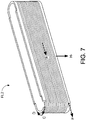
- the wrapping continues onto the second end of the adjacent freestanding electrically insulating former layer FL2 of the nest N 7L , and is wrapped on the outside of the adjacent freestanding electrically insulating former layer FL2 in a helical pattern from the second end to the first end, that is, in the direction H- indicated in FIGURE 7 which is opposite the direction H+ of wrapping of first former layer FL1 (cf. FIGURE 4 ).
- the wrapping of second former layer FL2 is diagrammatically indicated in FIGURE 7 by wrapping points C, D showing the transition from wrapping the first former layer FL1 to wrapping the second former layer FL2, point E denoting the wrapping of the former layer FL2 in the direction H-, and the "end" point F at which point the second former layer FL2 is fully wrapped. Notice that at this point F the end of the wire (which, again, actually continues on to the unillustrated wire spool from which the wire W is being fed) is back at the first end of the nest.
- the wire wrapping continues onto the next (third, in this instance) freestanding electrically insulating former layer FL3.
- the wrapping continues onto the first end of the adjacent freestanding electrically insulating former layer FL3 of the nest N 7L , and is wrapped on the outside of the adjacent freestanding electrically insulating former layer FL3 in a helical pattern from the first end to the second end, that is, in the direction H+ indicated in FIGURE 7 which is opposite the direction H- of wrapping of immediately previous (i.e., second) former layer FL2 ( cf. FIGURES 7 and 8 ).
- the wrapping of third former layer FL3 is diagrammatically indicated in FIGURE 8 by wrapping points G, H showing the transition from wrapping the second former layer FL2 to wrapping the third former layer FL3, point I denoting the wrapping of the former layer FL3 in the direction H+, and the "end" point J at which point the third former layer FL3 is fully wrapped.
- the nesting process is also performed during the wrapping.
- the first former layer FL1 is wrapped as described with reference to FIGURES 4 and 6 .
- the first former layer FL1 (including the wrapped wire) is nested inside the next (i.e., second) former layer FL2 in an operation Op2.
- the second former layer FL2 (with the first former layer FL1 nested therein) is then wrapped as described with reference to FIGURE 7 in an operation Op3.
- the second former layer FL1 (including the wrapped wire and with the first former layer FL1 nested inside) is nested inside the next (i.e., third) former layer FL3 in an operation Op4.
- the third former layer FL3 (with the first and second former layers FL1, FL2 nested therein) is then wrapped as described with reference to FIGURE 8 in an operation Op5.
- the nesting and wrapping operations are repeated until all seven former layers FL1 , FL2 , FL3 , FL4 , FL5 , FL6 , FL7 of the nest N 7L are wrapped by the single wire W.
- various approaches can be used to position and hold the inner freestanding electrically insulating former layer in the next-outer freestanding electrically insulating former layer (e.g., to hold former layer FL1 nested inside former layer FL2 in nesting operation Op2 ; to hold former layer FL2 nested inside former layer FL3 in nesting operation Op4 ; and so forth).
- the fitting is close enough to be compressively held.
- the wrapped wire around the inner former layer serves as a compressive "O-ring" type coupling for assisting this compressive fit.
- the former layers include mating elements, such as matched slots and protrusions or the like, to position and/or hold the inner former layer inside the next-outer former layer.
- Adhesives are also contemplated; however, the adhesive must remain operative at the high temperature or in other extreme conditions if the resulting electromagnet is to be operated at high temperature or in other extreme conditions. It is also contemplated to use a frame or the like to support the nest during the wrapping/nesting process and to then employ an external element such as a clamp or the like to secure the final nested assembly together in the final electromagnet.
- each such transition entails moving the wire "outward" to match the slightly larger diameter of the next former layer in the nest.
- each former layer except the last former layer FL7 ) includes a ramping structure at the "outlet" (that is, proximate to the wrapping point B in the case of the first former layer FL1; proximate to the wrapping point F in the case of the second former layer FL1; proximate to the wrapping point J in the case of the third former layer FL3; and so forth) that biases the wire outward.
- each former layer optionally includes a slot or other structure at the "inlet" (that is, proximate to the wrapping point C in the case of the second former layer FL1; proximate to the wrapping point G in the case of the third former layer FL3; and so forth) that facilitates receiving the wire onto the former layer to initiate the wrapping of that former layer.
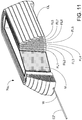
- FIGURE 10 illustrates that the number of former layers is a design parameter by illustrating a variant nest N 8L which includes the seven freestanding electrically insulating former layers FL1, FL2, FL3, FL4, FL5, FL6, FL7 and further includes an eighth freestanding electrically insulating former layer FL8, which is capped by the capping layer CL.
- the final electromagnet includes the first end E2' corresponding to the final end wire after wrapping the outermost freestanding electrically insulating former layer FL8 and cutting the wire off of the supply wire spool (not shown).
- the number of windings per layer is a design parameter for each layer (and may vary between layers) and for the electromagnet as a whole.
- the resulting electromagnet includes the multilayer electrical coil defined by the coil layers disposed on the former layers. When electrically energized, this multilayer electrical coil generates a magnetic field inside the multilayer electrical coil.
- the illustrative former layers have an inner cavity or opening that enables the electromagnet to be an air-core magnet (or a "water core” magnet if disposed in water-based primary coolant 14 ). As shown in FIGURES 10 and 11 , this inner cavity or opening is optionally filled with a ferromagnetic element M which substantially enhances the generated magnetic field.
- the ferromagnetic element M can be inserted after the wrapping is completed - in contrast, typically an electromagnet is formed by wrapping the windings directly around the ferromagnetic core.
- the ceramic or other electrically insulating material of the former layers is typically substantially less dense than iron, steel, or other ferromagnetic material, in manufacturing embodiments employing a fixed source wire spool this advantageously enables rotating a substantially lighter weight element respective to the spool during the wrapping.
- the disclosed electromagnets can be employed in any application in which an electromagnet is useful, and the disclosed electromagnets have especial application in high temperature environments, chemically caustic environments, radioactive environments, or other environments in which conventional wire insulation is likely to degrade and fail.
- the electromagnet comprises copper or silver (for the bare wire), zirconia toughened alumina (ZTA) or another ceramic material for the freestanding electrically insulating former layers, and optionally steel or another suitable ferromagnetic material for the core.
- ZTA zirconia toughened alumina
- These metals, and many ceramics including ZTA are highly resistant to high temperatures, caustic chemicals, radioactivity, and other environmental extremes.
- the disclosed electromagnets are robust for use in extreme environments such as inside the pressure vessel 12 of the illustrative nuclear reactor of FIGURE 1 .
- the disclosed electromagnets can be used in any application that utilizes an electromagnet, such as in a solenoid switch or other solenoid-based device, in an electric motor or any device including an electric motor, or so forth.
- each stator pole is embodied by an electromagnet EM comprising a nest of freestanding electrically insulating former layers wrapped with wire as disclosed herein.
- the illustrative multi-pole motor stator ST includes nine stator poles; however, in general a motor stator having any number of stator poles may be similarly constructed.
- the illustrative multi-pole motor stator ST includes a ferromagnetic yoke Y.
- the yoke Y includes integral ferromagnetic element M disposed inside the electrical coils of the electromagnets EM.
- ferromagnetic element M' disposed inside the electrical coils of the electromagnets EM include dovetail fittings that mount onto mating slots of the ferromagnetic yoke Y.
- FIGURE 14 can be convenient from a manufacturing standpoint, since the manufacturing can be broken into three parts: (1) wrapping and nesting the freestanding electrically insulating former layers to form the electrical coil; (2) inserting the ferromagnetic elements M' into the respective electrical coils to form individual ferromagnetic core-based electromagnets; and (3) installing the individual ferromagnetic core-based electromagnets onto the yoke Y using the dovetail mount fittings.
- the nest of former layers defining the electromagnets EM has a wedge shape that enables the nine electromagnets EM to be fitted closely together to form the circumferential arrangement of the nine-pole stator ST.
- this wedge shape is suitably attained by gradually reducing the height in the H+ (or, equivalently here, H- ) direction of the successively more outer former layers FL1, FL2, FL3, FL4, FL5, FL6, FL7 and, optionally, FL8.
- H+ or, equivalently here, H-
- other electromagnet geometries can be achieved using suitably shaped freestanding electrically insulating former layers.
- an elongated cylindrical solenoid can be formed using cylindrical former layers.
- FIGURE 15 shows a suitable embodiment of the CRDM 20 of the nuclear reactor of FIGURE 1
- FIGURE 16 shows a suitable embodiment of the coolant pump 26 of the nuclear reactor of FIGURE 1 .
- both devices 20, 26 are submerged in the primary coolant 14 and operate with the primary coolant 14 at an elevated operating temperature of at least 300°C in some embodiments, and at least 350°C in some embodiments.
- the stator ST is mounted in a rotationally and translationally fixed position, and rotates a rotor 70 that is coupled by a threaded connection with a lead screw 72.
- the lead screw 72 is prevented from rotating by a suitable mechanical stop (not shown), but can translate up/down in a translation direction 74.
- the combined effect is that as the multi-pole stator ST interacts with the rotor 70 to cause it to rotate, the rotor causes the lead screw 72 to translate up or down along the translation direction 74.
- a control rod 76 (shown in phantom in FIGURE 15 ) contains a neutron-absorbing material.
- the control rod 76 is connected with the lead screw 72 by a direct or indirect coupling 78 (diagrammatically indicated in FIGURE 15 ).
- the direct or indirect coupling 78 is via a spider or other coupling element or assembly that enables a plurality of control rods to be connected with the same lead screw 72. In this way, operation of the electric motor comprising the stator ST and rotor 70 drives the control rod 76 upward (that is, out of the reactor core 10 ) or downward (that is into the reactor core 10 ).
- the electric motor comprising the stator ST and the rotor 70 can be substantially any type of electric motor, such as a salient pole motor, a permanent magnet brushless DC motor, or so forth.
- the specific electric motor implemented depends upon the number and arrangement of stator electromagnets, and the type of rotor.
- the electric motor comprising the stator ST and the rotor 70 suitably operates as a stepper motor to enable precise positioning of the control rod 76 along the translation direction 74.
- the rotor includes an electromagnet which may also be embodied by a multilayer electrical coil supported by a nest of freestanding electrically insulating former layers as disclosed herein.
- the control rod system can include various modification that are not illustrated.
- the threaded connection between the lead screw 72 and the rotor 70 is in the form of a separable ball-nut which can separate to allow the assembly including the lead screw 72, coupling 78 (e.g., spider), and the control rod 76 to fall rapidly under the force of gravity toward the reactor core 10.
- LOCA loss of coolant accident
- the stator ST is mounted in a rotationally and translationally fixed position, and rotates a rotor 80.
- An impeller 82 connected with the rotor 80 so that the impeller 82 rotates with the rotor 80 to drive a primary coolant flow 14F (diagrammatically indicated by a large arrow drawn in phantom in FIGURE 16 ).
- this downward coolant flow 14F driven (or assisted) by the coolant pump 26 promotes the desired circulation of primary coolant in the pressure vessel 12 as described elsewhere herein with reference to FIGURE 1 .
- the electric motor comprising the stator ST and the rotor 80 is typically a continuously operating motor that drives the impeller 82 at a continuous rotational rate selected to generate a desired magnitude of the primary coolant flow 14F.
Landscapes
- Engineering & Computer Science (AREA)
- Physics & Mathematics (AREA)
- Power Engineering (AREA)
- Plasma & Fusion (AREA)
- General Engineering & Computer Science (AREA)
- High Energy & Nuclear Physics (AREA)
- Chemical & Material Sciences (AREA)
- Chemical Kinetics & Catalysis (AREA)
- Windings For Motors And Generators (AREA)
- Electromagnets (AREA)
- Insulation, Fastening Of Motor, Generator Windings (AREA)
- Connection Of Motors, Electrical Generators, Mechanical Devices, And The Like (AREA)
- Particle Accelerators (AREA)
- Iron Core Of Rotating Electric Machines (AREA)
Description
- The following relates to the electrical arts, electrical device arts, electromagnet arts, electric motor arts, nuclear reactor arts, and related arts.
- A pressurized water reactor (PWR) employs a pressure vessel containing superheated water as the primary coolant. Hot, subcooled water is circulated between the reactor core and one or more steam generators to transfer energy from the reactor core to the steam generator. In a conventional design, the steam generators are separate elements and the primary coolant is coupled between the pressure vessel and the steam generator via suitable high pressure fluid conduits. In an integral PWR design, the one or more steam generators are located inside the pressure vessel. Other types of nuclear reactors are similar. For example, a boiling water reactor (BWR) employs boiling primary coolant which is not superheated.
- It is advantageous to include motorized components inside the pressure vessel of a nuclear reactor. For example, in some reactor designs the primary coolant is actively circulated using electric motor-driven coolant pumps. The pumps may be located outside the pressure vessel and mechanically coupled with the impeller via a rotating shaft passing through a suitable vessel penetration. However, it is advantageous to eliminate the mechanical pass-through vessel penetration by employing wholly internal motor-driven coolant pumps. In this latter design, only small and mechanically static vessel penetrations for electrical cabling are employed.
- Another place where a motorized component can be useful is in control rod drive mechanism (CRDM) components. A control rod containing a neutron absorber is inserted partway or fully into the reactor core in order to moderate or stop the nuclear reaction. In so-called "gray" rods, the extent of the rod insertion is adjustable in a continuous or step-wise fashion in order to provide adjustable reactivity control. Traditionally, the electric motor operating the control rod is located outside the pressure vessel (typically above the pressure vessel in PWR designs or below the pressure vessel in BWR designs) and a connecting rod passes through a suitable vessel penetration to connect the CRDM motor with the control rod. Again, it is advantageous to eliminate the mechanical vessel penetration by employing a wholly internal CRDM in which the electric motor operating the control rod is located inside the pressure vessel, so that only mechanically static vessel penetrations for electrical cabling are employed.
- Employing electric motors inside the pressure vessel is complicated by the high temperature of the primary coolant. The electric motor and its constituent materials must be robust against the high temperature of the reactor environment, and must also be robust against other environmental conditions such as corrosive chemicals and/or radioactivity that may be present in the primary coolant. For example, PWR reactors typically employ boric acid as a soluble reactivity-moderating neutron poison in the primary coolant. Moreover, the electric motor must be reliable since any maintenance entails the costly proposition of shutting down and opening the reactor while taking suitable containment and radioactive waste control precautions. Document
WO9209092 DE1925182 andEP0395037 . - Disclosed herein are improvements that provide benefits that will become apparent to the skilled artisan upon reading the following.
- The invention is defined by the features of device claim 1. The dependent claims recite advantageous embodiments of the invention.
- The invention may take form in various components and arrangements of components, and in various process operations and arrangements of process operations. The drawings are only for purposes of illustrating preferred embodiments and are not to be construed as limiting the invention.
-
FIGURE 1 diagrammatically shows an illustrative pressurized water reactor (PWR) nuclear power system. -
FIGURES 2-11 show an electromagnet and various components and assembly aspects thereof. Of these,FIGURES 2 are top views,FIGURES 3 and5 are side sectional views,FIGURES 4 and6-8 are perspective views,FIGURE 9 is a diagrammatic assembly flow view,FIGURE 10 is a partially exploded perspective view, andFIGURE 11 is a perspective view in partial section. -
FIGURES 12-14 show embodiments of a multi-pole stator for an electric motor employing electromagnets as described with illustrative reference toFIGURES 2-11 as stator poles. Of these,FIGURE 12 is a perspective view,FIGURE 13 is a sectional perspective view, andFIGURE 14 is an end view. -
FIGURE 15 diagrammatically shows a side sectional view of a suitable embodiment of a control rod drive mechanism (CRDM) and coupled control rod of the PWR nuclear power system ofFIGURE 1 , in which the CRDM includes an electric motor with a multi-pole stator described with illustrative reference toFIGURES 12-14 . -
FIGURE 16 diagrammatically shows a side sectional view of a suitable embodiment of a coolant pump of the PWR nuclear power system ofFIGURE 1 , in which the coolant pump includes an electric motor with a multi-pole stator described with illustrative reference toFIGURES 12-14 . - With reference to
FIGURE 1 , a perspective sectional view an illustrative pressurized water nuclear reactor (PWR) including an integral steam generator is shown. Anuclear reactor core 10 is disposed inside a generallycylindrical pressure vessel 12, which containsprimary coolant 14, which in the illustrative case of a light water reactor is water (H2O) optionally containing additives such as soluble boric acid serving as a soluble neutron poison. The PWR includes asteam bubble 16 in the upper portion of the volume, with awater level 18 delineating between thesteam bubble 16 and the liquidprimary coolant 14. Pressure is adjusted via thesteam bubble 16, using electric heaters or the like or an external pressurizer (components not shown). - Reactor control is provided by a control rod drive mechanism (CRDM) 20 that is configured to controllably insert and withdraw neutron-absorbing control rods into and out of the
nuclear reactor core 10. TheCRDM 20 may be divided into multiple units, each controlling one or more control rods, in order to provide redundancy or other benefits. Theillustrative CRDM 20 is an internal system in which the drive motors and other components are disposed inside thepressure vessel 12 and submerged in theprimary coolant 14, with only electrical power and control wiring extending outside thepressure vessel 12. Alternatively, external CRDM may be employed. - The
pressure vessel 12 is configured to define a desired circulation of theprimary coolant 14. In the illustrative example, the circulation is defined by a hollow cylindricalcentral riser 22 disposed coaxially in the illustrativecylindrical pressure vessel 12.Primary coolant 14 heated by thereactor core 10 flows upward through fluid conduits passing through theinternal CRDM 20 and upward through the hollowcentral riser 22, discharges at the top of the hollowcentral riser 22 and is diverted downward by adiverter 24, flows downward through an annulus defined between the cylindricalcentral riser 22 and the walls of thecylindrical pressure vessel 12, and is then diverted upward at the bottom of thepressure vessel 12 to return to thereactor core 10. Optionalprimary coolant pumps 26 may be provided to drive the circulation of theprimary coolant 14, or to assist natural circulation of theprimary coolant 14. Theillustrative coolant pumps 26 are internal pumps which are wholly inside thepressure vessel 12 and submerged in theprimary coolant 14, with only electrical power and optional control wiring extending outside thepressure vessel 12. Alternatively, natural circulation may be relied upon for circulating the primary coolant. - The
pressure vessel 12 is suitably positioned substantially vertically. Anoptional skirt 30 may be provided to support thepressure vessel 12, or to bias against thepressure vessel 12 tipping over. Theillustrative skirt 30 is positioned such that the lower portion of thepressure vessel 12 containing thereactor core 10 is located in a recess below ground, which facilitates flooding for safety in the event of a loss of coolant accident (LOCA) or other accident. In the operative state of the nuclear reactor, theCRDM 20 withdraws (or at least partially withdraws) the control rods from thenuclear reactor core 10 to initiate a nuclear reaction in thecore 10. In a thermal nuclear reactor, theprimary coolant 14 serves as a neutron moderator to thermalize higher energy neutrons so as to maintain or enhance the nuclear reaction. In the operating state of a PWR, theprimary coolant 14 is superheated and is at a temperature of typically at least 300°C, and in some embodiments is at a temperature of at least 350°C. In the case of a BWR, the primary coolant is not superheated but is boiling, and the boiling primary coolant is typically at a temperature of at least at 300°C and in some embodiments at least 350°C. - To provide steam generation, the
primary coolant 14 heated by theoperating reactor core 10 is brought into thermal communication with a secondary coolant (typically light water, H2O optionally containing various additives, solutes, or so forth) flowing in a steam generator. In some embodiments (not illustrated), the steam generator is external to the pressure vessel and connected therewith by a relatively large-diameter vessel penetration carrying the primary coolant. In the illustrative embodiment ofFIGURE 1 , however, anintegral steam generator 32 is located inside thesame pressure vessel 12 containing thereactor core 10. The illustrativeintegral steam generator 32 is located in the annulus surrounding thecentral riser 22, that is, in the annular space between the exterior of thecentral riser 22 and the inside walls of thepressure vessel 12. Secondary coolant in the form of feedwater is input via afeedwater inlet 34 into an annular feedwater inlet plenum 36 (or, alternatively, into a tubesheet) where it feeds into a lower end of thesteam generator 32. The secondary coolant rises generally upward through thesteam generator 32 in secondary coolant flow paths or volume that are in thermal communication with (but in fluid isolation from) proximate primary coolant flow paths or volume through which primary coolant flows generally downward. (Note thatFIGURE 1 does not show details of the steam generator). The steam generator configuration can take various forms. In some embodiments, the steam generator comprises tubes carrying primary coolant generally downward, while the secondary coolant flows generally upward in a volume outside of the tubes. Alternatively, the secondary coolant may flow generally upward through the steam generator tubes while the primary coolant flows generally downward outside of the tubes. The tubes may comprise straight vertical tubes, slanted vertical tubes, helical tubes wrapping around thecentral riser 22, or so forth. However arranged, heat transfer takes place from the superheated primary coolant to the secondary coolant, which converts the secondary coolant from the liquid phase to the steam phase. In some embodiments the steam generator may include an integral economizer in a lower portion of the steam generator. In some embodiments, the steam generator may comprise a plurality of constituent steam generators to provide redundancy. The resulting steam enters an annular steam plenum 40 (or, alternatively, into a tubesheet) and from there passes out one ormore steam outlets 42. - The steam (whether generated by an integral steam generator such as the illustrative
integral steam generator 32, or by an external steam generator unit) can be used for substantially any purpose suitably accomplished using steam power. In the illustrative electrical plant ofFIGURE 1 , the steam drives aturbine 46 which in turn drives anelectrical power generator 48 to produce electrical power. Asteam condenser 50 downstream of theturbine 46 condenses the steam back into a liquid phase so as to recreate secondary coolant comprising feedwater. One ormore pumps more feedwater heaters feedwater inlet 34. Afeedwater valve 56 suitably controls the inlet feedwater flow rate. - The
internal CRDM 20 and the internal coolant pumps 26 are immersed in theprimary coolant 14, and should be robust against the elevated primary coolant temperature, which in some embodiments is at least 300°C and in some embodiments is at least 350°C. Conventional insulated wires typically undergo relatively rapid degradation at these temperatures which can lead to accelerated failure by arcing or shorting between loops of the constituent electrical coils. Disclosed herein are improved electromagnet components and motors employing same which are robust at the high operating temperature of the nuclear reactor. - With reference to
FIGURES 2 and 3 , an electromagnet includes plurality of nested freestanding electrically insulating former layers. The term "freestanding" connotes that the former layer does not collapse under its own weight, and moreover is capable of retaining its shape as electrically conductive wire is wrapped around the outside of the freestanding electrically insulating former layer to form the electromagnet as disclosed herein. The illustrative example ofFIGURES 2 and 3 shows a seven-layer nest N7L of seven freestanding electrically insulating former layers, namely an innermost or first freestanding electrically insulating former layer FL1 nested inside a second freestanding electrically insulating former layer FL2 nested inside a third freestanding electrically insulating former layer FL3 nested inside a fourth freestanding electrically insulating former layer FL4 nested inside a fifth freestanding electrically insulating former layer FL5 nested inside a sixth freestanding electrically insulating former layer FL6 nested inside a seventh freestanding electrically insulating former layer FL7. The electromagnet is formed by wrapping electrically conductive wire around the outsides of the freestanding electrically insulating former layers to form a multilayer electrical coil that when electrically energized generates a magnetic field inside the electrical coil. - With reference to
FIGURES 4-6 , the wrapping of wire around the outside of the first freestanding electrically insulating former layer FL1 is described.FIGURE 4 shows a perspective view of the first freestanding electrically insulating former layer FL1,FIGURE 5 shows a sectional end view of the first freestanding electrically insulating former layer FL1, andFIGURE 6 shows the perspective view of the first freestanding electrically insulating former layer FL1 shown inFIGURE 4 , but with electrically conductive wire W wrapped around the outside of it. The wire W wrapped around any given freestanding electrically insulating former layer defines a layer of the multilayer electrical coil. Within that layer, the wire is wrapped in a helical pattern in which the helical turns are spaced apart to avoid electrical arcing or shorting between neighboring helical turns. Said another way, the helical pattern has a helical pitch selected to be effective to avoid electrical arcing or shorting across neighboring helical turns for a range of interest of the electrical energizing. The spacing between neighboring helical turns is relied upon to avoid arcing or shorting, rather than relying upon an insulation of the wire. Accordingly, the electrically conductive wire is suitably (although not necessarily) bare electrically conductive wire not having electrical insulation. In some embodiments, the electrically conductive wire is bare copper wire not having electrical insulation. In some embodiments, the electrically conductive wire is bare silver wire not having electrical insulation. The minimum spacing between helical turns that is effective for avoiding arcing or shorting is readily ascertained based on the voltage across turns (which can be estimated, for example, as V/N where V is the applied voltage across the coil and N is the number of turns) and knowledge of breakdown voltage characteristics of the ambient in which the electrical coil resides. The minimum spacing may also be affected by other parameters such as the detailed shape of the helical turns. Any spacing larger than the minimum spacing effective for avoiding arcing or shorting is also suitable. - In some embodiments, the freestanding electrically insulating former layer has a smooth outside surface and the wire is wrapped around the freestanding electrically insulating former layer in the helical pattern with sufficient tightness that friction retains the helical turns in their initial positions so as to avoid movement and possible consequent arcing or shorting between neighboring helical turns.
- However, with particular reference to
FIGURES 4 and5 , in the illustrative embodiment a helical groove GV is formed in the outside surface of the freestanding electrically insulating former layer FL1 to retain the wire W in the desired helical pattern with the desired spacing between helical turns. As best seen in the inset ofFIGURE 5 , the illustrative groove GV has a hemispherical profile that is sized to receive the wire W (the wire W in this embodiment is assumed to have a circular cross-section). Although the groove GV is shown in detail and labeled only for the first freestanding electrically insulating former layer FL1, it is to be understood that in the illustrative embodiment each of the seven freestanding electrically insulating former layers FL1, FL2, FL3, FL4, FL5, FL6, FL7 includes such a helical groove for defining the helical pattern of the helically wound electrically conducting wire W. - The helical pitch or spacing between neighboring helical turns of the electrically conductive wire W ensures that arcing or shorting does not occur between neighboring turns within a layer of the multilayer electrical coil. On the other hand, the nest N7L ensures that there is a freestanding electrically insulating former layer disposed between any two neighboring layers of the multilayer electrical coil. The intervening freestanding electrically insulating former layer is of a material and thickness (taking into account any thickness reduction due to the helical groove GV) effective for avoiding arcing or shorting. Again, the minimum thickness and material is readily ascertained based on the voltage between layers (which can be estimated, for example, as V/NL where L is the number of layers in the multilayer coil, e.g. L=7 for the illustrative nest N7L , and V is the applied voltage across the coil) and knowledge of breakdown voltage characteristics of the material comprising the intervening freestanding electrically insulating former layer, and knowledge of the thickness of the freestanding electrically insulating former layer. Typically, the voltage is a design parameter, the number of layers is selected early in the design based on the magnetic field strength to be generated and the applied voltage specification, and the minimum thickness of the freestanding electrically insulating former layer effective for avoiding arcing or shorting is then estimated. Any thickness larger than the minimum thickness effective for avoiding arcing or shorting is also suitable.
- As already noted, in estimating the minimum thickness any thickness reduction due to the helical groove GV should be taken into account. However, in doing so it is contemplated to arrange the helical groove on neighboring freestanding electrically insulating former layers to provide some additional "lateral" spacing to aid in preventing arcing or shorting between layers. For example, by offsetting the helical patterns of neighboring layers by one-half of the helical pitch additional nearest-neighbor spatial separation is achieved.
- The outermost freestanding electrically insulating former layer, namely the seventh freestanding electrically insulating former layer FL7 in the illustrative seven-layer nest N7L , has wire wrapped on its outside to form the outermost layer of the multilayer electrical coil. This outermost coil layer has only one neighboring coil layer, namely the sixth coil layer wrapped on the outside of the next-inward freestanding electrically insulating former layer FL6. Thus, there is no need for an electrically insulating layer outward of the outermost coil layer in order to prevent outward arcing or shorting to a more outer neighboring coil layer (since none exists). However, depending upon the application it may be undesirable to leave the outermost coil layer exposed, since it could contact some other component and thus create an electrical hazard. To prevent such an occurrence, in the illustrative example (see
FIGURES 2 and 3 ) a capping freestanding electrically insulating layer CL is disposed around the plurality of nested freestanding electrically insulating former layers, that is, around the nest N7L . The purpose of this cap layer CL is to prevent contact with the outermost coil layer. - It should be noted that the use of the term "helical pitch" herein does not require that the helical pattern have a uniform helical pitch over the entire helical pattern. In some electromagnet designs it may be advantageous to use a smaller pitch in certain areas to increase the local electrical field and/or a larger pitch in certain areas to reduce the local electrical field, and such variations are contemplated. Similar considerations may lead to a design in which the freestanding electrically insulating former layer has variable thickness. In such cases, the "local" helical pitch and "local" thickness should be everywhere sufficient to prevent arcing or shorting between nearest-neighbor (both in-layer and interlayer) helical turns.
- As already noted, each freestanding electrically insulating former layer should have the mechanical property of not collapsing under its own weight and being capable of retaining its shape as electrically conductive wire is wrapped around its outside. As further already noted, each freestanding electrically insulating former layer should also have dielectric properties (in combination with sufficient thickness) to prevent electrical arcing or shorting across layers of the multilayer electrical coil for a range of interest of the electrical energizing (for example, as specified by a maximum applied voltage). Still further, the each freestanding electrically insulating former layer should be electrically insulating, meaning that its electrical conductivity is sufficiently low that electrical conduction through the former layer is negligible (for example, as defined by an acceptable "leakage current" across the former layer which may in some embodiments be below the measurable limit) for the range of interest of the electrical energizing. Another material constraint is that the material of the freestanding electrically insulating former layers should be sufficiently heat resistant to avoid problematic degradation at operating temperature (which, by way of illustrative example, in some nuclear reactor applications may be at least 300°C, and in some nuclear reactor applications may be at least 350°C). For suitable ceramic, metallic, or other selected materials, the wrapped former layers are expected to be operative at temperatures well above 500°C.
- Based on these considerations, various materials can be identified as suitable for use as the electrically insulating former layers. In some embodiments, the freestanding electrically insulating former layers comprise a ceramic material. In some embodiments, the freestanding electrically insulating former layers comprise a zirconia toughened alumina (ZTA) material. Various other materials with the requisite mechanical, electrical, and thermal resistance properties are also contemplated. The optional capping freestanding electrically insulating layer CL is suitably made of the same material as the electrically insulating former layers, although it could be made of a different (but still electrically insulating and thermally resistant) material. If made of a different material, in some such embodiments the cap layer CL is not freestanding.
- The pattern of the winding of the electrically conductive wire W on the freestanding electrically insulating former layers FL1, FL2, FL3, FL4, FL5, FL6, FL7 of the nest N7L is such that the electrically conductive wire W is wrapped around the outside of each freestanding electrically insulating former layer to form a helical wrapped wire layer in a helical pattern oriented such that the contributions to the magnetic field inside the multilayer electrical coil from the helical wrapped wire layers around the outsides of all freestanding electrically insulating former layers of the nest N7L are additive. In some embodiments, each of the freestanding electrically insulating former layers is wrapped with a separate wire, so that, for example, in the case of the seven-layer nest N7L there would be fourteen terminal wires (two for each layer), and these terminal wires can be externally interconnected and/or connected with voltage sources to apply voltage of the desired polarity to each layer so as to additively combine the generated magnetic fields inside the multilayer electric coil. However, this approach has the disadvantage of entailing a substantial amount of external wiring and concomitant external components.
- In the illustrative example, the electrically conductive wire W comprises a single electrically conductive wire W that is wrapped around all seven freestanding electrically insulating former layers FL1, FL2, FL3, FL4, FL5, FL6, FL7 of the nest N7L . To make this work, the wrapping pattern should satisfy the additional constraint that once one layer is wrapped the wire is conveniently extended onto the next layer of the nest N7L .
- With reference to
FIGURE 4 and further reference toFIGURES 7 and8 (showing perspective views of the second and third former layers FL2, FL3, respectively), a suitable continuous wrapping approach is described for continuously wrapping the single wire W onto multiple former layers of the nest N7L to generate additively combining magnetic field contributions inside the multilayer coil. The wrapping is described with reference to wrapping "points" A, B, C, D, E, F, G, H, I, J which are diagrammatically indicated inFIGURES 4 ,7 , and8 by dashed arrows. The wrapping points A, B shown inFIGURE 4 depict a suitable wrapping of the first freestanding electrically insulating former layer FL1. This wrapping is suitably accomplished by wrapping the outside of the first freestanding electrically insulating former layer FL1 of the nest N7L in a helical pattern from a first end to an opposite second end (that is, in the direction H+ indicated by an arrow inFIGURE 4 ). The wrapping point A is during the wrapping of the former layer FL1, while the wrapping point B is at the point when the first former layer FL1 is completely wrapped. -
FIGURE 6 shows the fully wrapped first former layer FL1. At this point in the wrapping process, there is a dangling end E1, and an "end" E2 which actually goes to the wire spool (not shown) from which the electrically conductive wire W is being unwound. It is also noted that while the description here is in terms of the wire W being wound around the apparently stationary former layer FL1, in some embodiments the winding is performed by rotating the former layer FL1 while keeping the wire spool fixed. - With particular reference to
FIGURE 7 , the wire wrapping continues onto the next (second, in this instance) freestanding electrically insulating former layer FL2. The wrapping continues onto the second end of the adjacent freestanding electrically insulating former layer FL2 of the nest N7L , and is wrapped on the outside of the adjacent freestanding electrically insulating former layer FL2 in a helical pattern from the second end to the first end, that is, in the direction H- indicated inFIGURE 7 which is opposite the direction H+ of wrapping of first former layer FL1 (cf.FIGURE 4 ). The wrapping of second former layer FL2 is diagrammatically indicated inFIGURE 7 by wrapping points C, D showing the transition from wrapping the first former layer FL1 to wrapping the second former layer FL2, point E denoting the wrapping of the former layer FL2 in the direction H-, and the "end" point F at which point the second former layer FL2 is fully wrapped. Notice that at this point F the end of the wire (which, again, actually continues on to the unillustrated wire spool from which the wire W is being fed) is back at the first end of the nest. - With particular reference to
FIGURE 8 , the wire wrapping continues onto the next (third, in this instance) freestanding electrically insulating former layer FL3. The wrapping continues onto the first end of the adjacent freestanding electrically insulating former layer FL3 of the nest N7L , and is wrapped on the outside of the adjacent freestanding electrically insulating former layer FL3 in a helical pattern from the first end to the second end, that is, in the direction H+ indicated inFIGURE 7 which is opposite the direction H- of wrapping of immediately previous (i.e., second) former layer FL2 (cf.FIGURES 7 and8 ). The wrapping of third former layer FL3 is diagrammatically indicated inFIGURE 8 by wrapping points G, H showing the transition from wrapping the second former layer FL2 to wrapping the third former layer FL3, point I denoting the wrapping of the former layer FL3 in the direction H+, and the "end" point J at which point the third former layer FL3 is fully wrapped. - This wrapping process continues on for each successive former layer until all seven former layers FL1, FL2, FL3, FL4, FL5, FL6, FL7 of the nest N7L are wrapped by the single wire W.
- With reference to
FIGURE 9 , the nesting process is also performed during the wrapping. Thus, in an operation Op1 the first former layer FL1 is wrapped as described with reference toFIGURES 4 and6 . Once this first wrapping operation Op1 is completed, the first former layer FL1 (including the wrapped wire) is nested inside the next (i.e., second) former layer FL2 in an operation Op2. The second former layer FL2 (with the first former layer FL1 nested therein) is then wrapped as described with reference toFIGURE 7 in an operation Op3. Once this second wrapping operation Op3 is completed, the second former layer FL1 (including the wrapped wire and with the first former layer FL1 nested inside) is nested inside the next (i.e., third) former layer FL3 in an operation Op4. The third former layer FL3 (with the first and second former layers FL1, FL2 nested therein) is then wrapped as described with reference toFIGURE 8 in an operation Op5. The nesting and wrapping operations are repeated until all seven former layers FL1, FL2, FL3, FL4, FL5, FL6, FL7 of the nest N7L are wrapped by the single wire W. - In the nesting operations, e.g. the operations Op2, Op4 in illustrative
FIGURE 9 , various approaches can be used to position and hold the inner freestanding electrically insulating former layer in the next-outer freestanding electrically insulating former layer (e.g., to hold former layer FL1 nested inside former layer FL2 in nesting operation Op2; to hold former layer FL2 nested inside former layer FL3 in nesting operation Op4; and so forth). In some embodiments, the fitting is close enough to be compressively held. Optionally, the wrapped wire around the inner former layer serves as a compressive "O-ring" type coupling for assisting this compressive fit. In other embodiments (not illustrated), the former layers include mating elements, such as matched slots and protrusions or the like, to position and/or hold the inner former layer inside the next-outer former layer. Adhesives are also contemplated; however, the adhesive must remain operative at the high temperature or in other extreme conditions if the resulting electromagnet is to be operated at high temperature or in other extreme conditions. It is also contemplated to use a frame or the like to support the nest during the wrapping/nesting process and to then employ an external element such as a clamp or the like to secure the final nested assembly together in the final electromagnet. - In transitioning the wire wrapping between former layers, as in going from the end of the wrapping operation Op1 to the start of the next wrapping operation Op3, or in going from the end of the wrapping operation Op3 to the start of the next wrapping operation Op5, or so forth, each such transition entails moving the wire "outward" to match the slightly larger diameter of the next former layer in the nest. Optionally, each former layer (except the last former layer FL7) includes a ramping structure at the "outlet" (that is, proximate to the wrapping point B in the case of the first former layer FL1; proximate to the wrapping point F in the case of the second former layer FL1; proximate to the wrapping point J in the case of the third former layer FL3; and so forth) that biases the wire outward. Similarly, each former layer (except the first former layer FL1) optionally includes a slot or other structure at the "inlet" (that is, proximate to the wrapping point C in the case of the second former layer FL1; proximate to the wrapping point G in the case of the third former layer FL3; and so forth) that facilitates receiving the wire onto the former layer to initiate the wrapping of that former layer.
- With reference to
FIGURES 10 and11 , the final result of the single-wire wrapping process described with reference toFIGURES 4 and6-9 is a multi-layer nest of freestanding electrically insulating former layers with wire wrapped around the former layers.FIGURE 10 illustrates that the number of former layers is a design parameter by illustrating a variant nest N8L which includes the seven freestanding electrically insulating former layers FL1, FL2, FL3, FL4, FL5, FL6, FL7 and further includes an eighth freestanding electrically insulating former layer FL8, which is capped by the capping layer CL. The final electromagnet includes the first end E2' corresponding to the final end wire after wrapping the outermost freestanding electrically insulating former layer FL8 and cutting the wire off of the supply wire spool (not shown). While illustrative examples with seven or eight former layers are shown by way of illustrative example, it is to be understood that the number of layers is a design parameter, and values as small as L=1 (a single layer, either with or without a capping layer) or L=2 (two layers, optionally with an additional capping layer) are contemplated. In similar fashion, the number of windings per layer is a design parameter for each layer (and may vary between layers) and for the electromagnet as a whole. - The resulting electromagnet includes the multilayer electrical coil defined by the coil layers disposed on the former layers. When electrically energized, this multilayer electrical coil generates a magnetic field inside the multilayer electrical coil. The illustrative former layers have an inner cavity or opening that enables the electromagnet to be an air-core magnet (or a "water core" magnet if disposed in water-based primary coolant 14). As shown in
FIGURES 10 and11 , this inner cavity or opening is optionally filled with a ferromagnetic element M which substantially enhances the generated magnetic field. Optionally, the ferromagnetic element M can be inserted after the wrapping is completed - in contrast, typically an electromagnet is formed by wrapping the windings directly around the ferromagnetic core. Since the ceramic or other electrically insulating material of the former layers is typically substantially less dense than iron, steel, or other ferromagnetic material, in manufacturing embodiments employing a fixed source wire spool this advantageously enables rotating a substantially lighter weight element respective to the spool during the wrapping. - The disclosed electromagnets can be employed in any application in which an electromagnet is useful, and the disclosed electromagnets have especial application in high temperature environments, chemically caustic environments, radioactive environments, or other environments in which conventional wire insulation is likely to degrade and fail. In some embodiments, the electromagnet comprises copper or silver (for the bare wire), zirconia toughened alumina (ZTA) or another ceramic material for the freestanding electrically insulating former layers, and optionally steel or another suitable ferromagnetic material for the core. These metals, and many ceramics including ZTA, are highly resistant to high temperatures, caustic chemicals, radioactivity, and other environmental extremes. Accordingly, the disclosed electromagnets are robust for use in extreme environments such as inside the
pressure vessel 12 of the illustrative nuclear reactor ofFIGURE 1 . In general, the disclosed electromagnets can be used in any application that utilizes an electromagnet, such as in a solenoid switch or other solenoid-based device, in an electric motor or any device including an electric motor, or so forth. - With reference to
FIGURES 12-14 , an illustrative multi-pole motor stator ST is shown, in which each stator pole is embodied by an electromagnet EM comprising a nest of freestanding electrically insulating former layers wrapped with wire as disclosed herein. The illustrative multi-pole motor stator ST includes nine stator poles; however, in general a motor stator having any number of stator poles may be similarly constructed. - With continuing reference to
FIGURES 12-14 , the illustrative multi-pole motor stator ST includes a ferromagnetic yoke Y. In the variant embodiment shown in the sectional perspective view ofFIGURE 13 , the yoke Y includes integral ferromagnetic element M disposed inside the electrical coils of the electromagnets EM. In the variant embodiment shown in the end view ofFIGURE 14 , ferromagnetic element M' disposed inside the electrical coils of the electromagnets EM include dovetail fittings that mount onto mating slots of the ferromagnetic yoke Y. The latter design ofFIGURE 14 can be convenient from a manufacturing standpoint, since the manufacturing can be broken into three parts: (1) wrapping and nesting the freestanding electrically insulating former layers to form the electrical coil; (2) inserting the ferromagnetic elements M' into the respective electrical coils to form individual ferromagnetic core-based electromagnets; and (3) installing the individual ferromagnetic core-based electromagnets onto the yoke Y using the dovetail mount fittings. - As seen in
FIGURES 12-14 , the nest of former layers defining the electromagnets EM has a wedge shape that enables the nine electromagnets EM to be fitted closely together to form the circumferential arrangement of the nine-pole stator ST. Review ofFIGURES 3 ,10 , and11 shows that this wedge shape is suitably attained by gradually reducing the height in the H+ (or, equivalently here, H-) direction of the successively more outer former layers FL1, FL2, FL3, FL4, FL5, FL6, FL7 and, optionally, FL8. In similar fashion other electromagnet geometries can be achieved using suitably shaped freestanding electrically insulating former layers. For example, an elongated cylindrical solenoid can be formed using cylindrical former layers. - With reference to
FIGURES 15 and 16 , the illustrative multi-pole stator ST can be used in various devices that employ an electric motor. By way of illustrative example,FIGURE 15 shows a suitable embodiment of theCRDM 20 of the nuclear reactor ofFIGURE 1 , whileFIGURE 16 shows a suitable embodiment of thecoolant pump 26 of the nuclear reactor ofFIGURE 1 . As already described, bothdevices primary coolant 14 and operate with theprimary coolant 14 at an elevated operating temperature of at least 300°C in some embodiments, and at least 350°C in some embodiments. - With particular reference to
FIGURE 15 , in theillustrative CRDM 20 the stator ST is mounted in a rotationally and translationally fixed position, and rotates arotor 70 that is coupled by a threaded connection with alead screw 72. Thelead screw 72 is prevented from rotating by a suitable mechanical stop (not shown), but can translate up/down in atranslation direction 74. The combined effect is that as the multi-pole stator ST interacts with therotor 70 to cause it to rotate, the rotor causes thelead screw 72 to translate up or down along thetranslation direction 74. Downward motion of thelead screw 72 is achieved by rotating therotor 70 in one direction (e.g., clockwise) while upward motion of thelead screw 72 is achieved by rotating therotor 70 in the opposite direction (e.g., counterclockwise). A control rod 76 (shown in phantom inFIGURE 15 ) contains a neutron-absorbing material. Thecontrol rod 76 is connected with thelead screw 72 by a direct or indirect coupling 78 (diagrammatically indicated inFIGURE 15 ). In some embodiments, the direct orindirect coupling 78 is via a spider or other coupling element or assembly that enables a plurality of control rods to be connected with thesame lead screw 72. In this way, operation of the electric motor comprising the stator ST androtor 70 drives thecontrol rod 76 upward (that is, out of the reactor core 10) or downward (that is into the reactor core 10). - The electric motor comprising the stator ST and the
rotor 70 can be substantially any type of electric motor, such as a salient pole motor, a permanent magnet brushless DC motor, or so forth. The specific electric motor implemented depends upon the number and arrangement of stator electromagnets, and the type of rotor. For gray rod control in which the amount of insertion of thecontrol rod 76 into thereactor core 10 is intended to be continuously (or quasi-continuously) adjustable, the electric motor comprising the stator ST and therotor 70 suitably operates as a stepper motor to enable precise positioning of thecontrol rod 76 along thetranslation direction 74. Although not illustrated, it should be noted that in some types of motors the rotor includes an electromagnet which may also be embodied by a multilayer electrical coil supported by a nest of freestanding electrically insulating former layers as disclosed herein. - The control rod system can include various modification that are not illustrated. For example, in some embodiments the threaded connection between the
lead screw 72 and therotor 70 is in the form of a separable ball-nut which can separate to allow the assembly including thelead screw 72, coupling 78 (e.g., spider), and thecontrol rod 76 to fall rapidly under the force of gravity toward thereactor core 10. Such a rapid release is advantageously during a loss of coolant accident (LOCA) or other emergency event in which the reactivity of thecore 10 is to be rapidly extinguished. - With particular reference to
FIGURE 16 , in theillustrative coolant pump 26 the stator ST is mounted in a rotationally and translationally fixed position, and rotates arotor 80. Animpeller 82 connected with therotor 80 so that theimpeller 82 rotates with therotor 80 to drive aprimary coolant flow 14F (diagrammatically indicated by a large arrow drawn in phantom inFIGURE 16 ). For coolant pumps 26 positioned in the outer annulus as shown in the illustrative reactor example ofFIGURE 1 , thisdownward coolant flow 14F driven (or assisted) by thecoolant pump 26 promotes the desired circulation of primary coolant in thepressure vessel 12 as described elsewhere herein with reference toFIGURE 1 . For the pump application ofFIGURE 16 , the electric motor comprising the stator ST and therotor 80 is typically a continuously operating motor that drives theimpeller 82 at a continuous rotational rate selected to generate a desired magnitude of theprimary coolant flow 14F. - Variations and modifications are possible within the scope of the appended claims.
Claims (15)
- An apparatus comprising:
an electromagnet (EM) having a bottom end, a top end, and a central axis extending therebetween, the width perpendicular to the central axis at the top end being less than the width perpendicular to the central axis at the bottom end defining a wedge shape for the electromagnet (EM), the electromagnet (EM) comprising:a nest (N7L, N8L) with a plurality of nested freestanding electrically insulating former layers (FL1, FL2, FL3, FL4, FL5, FL6, FL7, FL8), each of the freestanding electrically insulating former layers (FL1, FL2, FL3, FL4, FL5, FL6, FL7, FL8) having a height in a direction parallel to the central axis; andelectrically conductive wire (W) wrapped around the outsides of the freestanding electrically insulating former layers (FL1, FL2, FL3, FL4, FL5, FL6, FL7, FL8) to define a multilayer electrical coil in which adjacent layers of the multilayer electrical coil are spaced apart by intervening freestanding electrically insulating former layers (FL1, FL2, FL3, FL4, FL5, FL6, FL7, FL8); wherein electrically energizing the multilayer electrical coil generates a magnetic field inside the multilayer electrical coil. - The apparatus as set forth in claim 1, further comprising:
a ferromagnetic core disposed inside the multilayer electrical coil, optionally wherein the ferromagnetic core defines a support that supports the electromagnet comprising the plurality of nested freestanding electrically insulating former layers (FL1, FL2, FL3, FL4, FL5, FL6, FL7, FL8) and the electrically conductive wire (W). - The apparatus as set forth in claim 1, wherein the electrically conductive wire (W) is selected from the group comprising: bare electrically conductive wire (W) not having electrical insulation;
bare copper wire (W) not having electrical insulation; and
bare silver wire (W) not having electrical insulation. - The apparatus as set forth in claim 1, wherein the electrically conductive wire (W) is wrapped around the outside of each freestanding electrically insulating former layer (FL1, FL2, FL3, FL4, FL5, FL6, FL7, FL8) in a helical pattern having a helical pitch effective to avoid electrical arcing or shorting across neighboring helical turns for a range of interest of the electrical energizing.
- The apparatus as set forth in claim 1, wherein the electrically conductive wire (W) is wrapped around the outside of each freestanding electrically insulating former layer (FL1, FL2, FL3, FL4, FL5, FL6, FL7, FL8) to form a helical wrapped wire layer in a helical pattern oriented such that the contributions to the magnetic field inside the multilayer electrical coil from the helical wrapped wire layers around the outsides of all freestanding electrically insulating former layers (FL1, FL2, FL3, FL4, FL5, FL6, FL7, FL8) of the nest (N7L, N8L) are additive, optionally wherein the helical wrapped wire layer around the outside of each freestanding electrically insulating former layer (FL1, FL2, FL3, FL4, FL5, FL6, FL7, FL8) is wrapped with a helix axis direction opposite the helix axis direction of the helical wrapped wire layers of the one or two neighboring freestanding electrically insulating former layers (FL1, FL2, FL3, FL4, FL5, FL6, FL7, FL8) the nest (N7L, N8L).
- The apparatus as set forth in claim 1 or 3, wherein each freestanding electrically insulating former layer (FL1, FL2, FL3, FL4, FL5, FL6, FL7, FL8) includes a helical groove (GV) defined around the outside of the electrically insulating former layer (FL1, FL2, FL3, FL4, FL5, FL6, FL7, FL8) and the electrically conductive wire (W) is wrapped around the outside of the freestanding electrically insulating former layer (FL1, FL2, FL3, FL4, FL5, FL6, FL7, FL8) in a helical pattern with spaced apart helical turns and is retained by the helical groove (GV).
- The apparatus as set forth in claim 1, wherein:each freestanding electrically insulating former layer (FL1, FL2, FL3, FL4, FL5, FL6, FL7, FL8) includes a helical groove (GV) defined around the outside of the electrically insulating former layer (FL1, FL2, FL3, FL4, FL5, FL6, FL7, FL8) that retains the bare electrically conductive wire (W) wrapped around the outside of the freestanding electrically insulating former layer (FL1, FL2, FL3, FL4, FL5, FL6, FL7, FL8) in a helical pattern comprising spaced apart helical turns of the bare electrically conductive wire (W); andthe electrically conductive wire (W) comprises a single electrically conductive wire (W) that:is wrapped on the outside of a first freestanding electrically insulating former layer (FL1, FL2, FL3, FL4, FL5, FL6, FL7, FL8) of the nest (NL7, NL8) in a helical pattern from a first end to an opposite second end,continues onto the second end of an adjacent freestanding electrically insulating former layer (FL1, FL2, FL3, FL4, FL5, FL6, FL7, FL8) of the nest (NL7, NL8), andis wrapped on the outside of the adjacent freestanding electrically insulating former layer (FL1, FL2, FL3, FL4, FL5, FL6, FL7, FL8) in a helical pattern from the second end to the first end.
- The apparatus as set forth in claim 1, wherein the freestanding electrically insulating former layers (FL1, FL2, FL3, FL4, FL5, FL6, FL7, FL8) comprise one of the group comprising: a ceramic material; and a zirconia toughened alumina (ZTA) material.
- The apparatus as set forth in claim 1, wherein the electromagnet (EM) further comprises:
a capping freestanding electrically insulating layer (CL) disposed around the plurality of nested freestanding electrically insulating former layers ((FL1, FL2, FL3, FL4, FL5, FL6, FL7, FL8). - The apparatus as set forth in claim 1, further comprising:
an electric motor including a rotor (70) and a stator (ST); wherein said electromagnet (EM) defines a pole of the stator (ST). - The apparatus as set forth in claim 10, wherein the stator (ST) of the electric motor is a multi-pole stator (ST) comprising a plurality of said electromagnets (EM), optionally further comprising a ferromagnetic yoke (Y) including a plurality of ferromagnetic poles corresponding to the plurality of electromagnets (EM), with each ferromagnetic pole disposed inside the multilayer electrical coil of a corresponding electromagnet (EM) to define a stator pole of the multi-pole stator (ST), and optionally wherein the ferromagnetic yoke (Y) defines a support frame of the multi-pole stator (ST) and the electromagnets (EM) are mounted on corresponding ferromagnetic poles of the ferromagnetic yoke (Y).
- The apparatus as set forth in claim 10, further comprising:
a control rod drive mechanism (CRDM) including said motor and a lead screw (72), the motor operatively coupled with the lead screw (72) to linearly drive the lead screw (72) whereby a control rod (76) containing a neutron poison connected with the lead screw (72) is linearly driven into or out of a nuclear reactor core (10). - The apparatus as set forth in claim 10, further comprising:
a fluid pump (26) including said motor operatively connected with an r impeller (82). - The apparatus as set forth in claim 10, further comprising:a nuclear reactor (PWR) including a pressure vessel (12) containing primary coolant (14) and a nuclear reactor core (10) disposed in the pressure vessel (12) and operative to maintain the primary coolant (14) at a temperature of at least 300°C; anda control rod drive mechanism (CRDM) submerged in the primary coolant (14), the control rod drive mechanism (CRDM) including said motor operatively coupled with a control rod (76) containing a neutron poison to linearly drive the control rod (76) into or out of the nuclear reactor core (10).
- The apparatus as set forth in claim 10, further comprising:a nuclear reactor (PWR) including a pressure vessel (12) containing primary coolant (14) and a nuclear reactor core (10) disposed in the pressure vessel and operative to maintain the primary coolant (14) at a temperature of at least 300°C; anda coolant pump (26) including said motor operatively connected with an impeller (82), the coolant pump (26) submerged in the primary coolant (14) and arranged to circulate or assist natural circulation of the primary coolant (14) in the pressure vessel(12).
Applications Claiming Priority (2)
| Application Number | Priority Date | Filing Date | Title |
|---|---|---|---|
| US13/188,946 US9985488B2 (en) | 2011-07-22 | 2011-07-22 | Environmentally robust electromagnets and electric motors employing same for use in nuclear reactors |
| PCT/US2012/046382 WO2013016000A2 (en) | 2011-07-22 | 2012-07-12 | Environmentally robust electromagnets and electric motors employing same for use in nuclear reactors |
Publications (4)
| Publication Number | Publication Date |
|---|---|
| EP2735001A2 EP2735001A2 (en) | 2014-05-28 |
| EP2735001A4 EP2735001A4 (en) | 2015-12-16 |
| EP2735001B1 true EP2735001B1 (en) | 2018-07-11 |
| EP2735001B8 EP2735001B8 (en) | 2019-01-09 |
Family
ID=47534472
Family Applications (1)
| Application Number | Title | Priority Date | Filing Date |
|---|---|---|---|
| EP12817197.2A Active EP2735001B8 (en) | 2011-07-22 | 2012-07-12 | Environmentally robust electromagnets and electric motors employing same for use in nuclear reactors |
Country Status (9)
| Country | Link |
|---|---|
| US (2) | US9985488B2 (en) |
| EP (1) | EP2735001B8 (en) |
| JP (1) | JP2014523228A (en) |
| KR (1) | KR20140037916A (en) |
| CN (1) | CN102890994A (en) |
| AR (1) | AR087219A1 (en) |
| CA (1) | CA2841004C (en) |
| TW (1) | TW201312591A (en) |
| WO (1) | WO2013016000A2 (en) |
Families Citing this family (9)
| Publication number | Priority date | Publication date | Assignee | Title |
|---|---|---|---|---|
| US9985488B2 (en) | 2011-07-22 | 2018-05-29 | RWXT Nuclear Operations Group, Inc. | Environmentally robust electromagnets and electric motors employing same for use in nuclear reactors |
| KR20150049203A (en) * | 2013-10-29 | 2015-05-08 | 삼성전기주식회사 | Haptic touch module |
| EP3079242A1 (en) * | 2015-04-10 | 2016-10-12 | Siemens Aktiengesellschaft | Manufacturing method of winding around a salient pol for a synchronous engine |
| WO2016176048A1 (en) * | 2015-04-28 | 2016-11-03 | Parker-Hannifin Corporation | Low profile miniature solenoid proportional valve |
| GB2542107B (en) * | 2015-04-29 | 2021-12-01 | Cummins Generator Technologies | Winding former |
| JPWO2018062118A1 (en) * | 2016-09-28 | 2019-08-15 | 日本電産株式会社 | Non-contact power supply coil unit |
| CN113304535B (en) * | 2021-05-26 | 2022-05-13 | 中国原子能科学研究院 | Filtering component for lead-bismuth cooling reactor purifying device |
| US20250239904A1 (en) * | 2024-01-18 | 2025-07-24 | Flowserve Pte. Ltd. | Coil assembly of an integrated motor pump or turbine having reduced thermal stress at cryogenic temperatures |
| EP4618114A1 (en) * | 2024-03-15 | 2025-09-17 | Delta Electronics (Thailand) Public Co., Ltd. | Bobbin and magnetic component |
Family Cites Families (84)
| Publication number | Priority date | Publication date | Assignee | Title |
|---|---|---|---|---|
| US2982888A (en) | 1957-05-23 | 1961-05-02 | Rea Magnet Wire Company Inc | Sleeve type encapsulated electrical component |
| DE1250019B (en) | 1963-07-19 | |||
| US3389055A (en) | 1965-04-05 | 1968-06-18 | Gen Electric | Jet pump assembly in a nuclear reactor |
| DE1925182A1 (en) | 1969-05-17 | 1970-11-19 | Zahnradfabrik Friedrichshafen | Solenoid |
| CH592352A5 (en) | 1974-03-20 | 1977-10-31 | Commissariat Energie Atomique | |
| DE2442500C2 (en) | 1974-09-05 | 1984-06-28 | Interatom Internationale Atomreaktorbau Gmbh, 5060 Bergisch Gladbach | Pressurized water reactor |
| US4072563A (en) | 1976-06-24 | 1978-02-07 | The Babcock & Wilcox Company | Industrial technique for an integral compact reactor |
| US5174945A (en) | 1976-12-30 | 1992-12-29 | Fdx Patents Holding Company, N.V. | Controlled thermonuclear fusion power apparatus and method |
| US4252605A (en) | 1977-08-15 | 1981-02-24 | General Atomic Company | Self-imploding liner system for magnetic field compression |
| US4238288A (en) | 1978-05-24 | 1980-12-09 | Anikin Alexandr A | Drive of nuclear reactor S control element |
| JPS599877B2 (en) | 1979-04-28 | 1984-03-05 | 株式会社日立製作所 | Reactor |
| US4423002A (en) | 1979-12-19 | 1983-12-27 | Framatome | Apparatus for controlling a nuclear reactor by vertical displacement of a unit absorbing neutrons |
| US4734250A (en) | 1984-03-28 | 1988-03-29 | Westinghouse Electric Corp. | Concentric pipe loop arrangement for pressurized water nuclear reactors |
| US4696792A (en) | 1984-07-30 | 1987-09-29 | General Electric Company | Nuclear reactor coolant recirculation |
| FR2576706B1 (en) | 1985-01-29 | 1987-04-17 | Framatome Sa | ELECTROMAGNETIC CONTROL BAR CONTROL DEVICE WITH REDUCED THERMAL LOSSES |
| US4765948A (en) * | 1986-08-29 | 1988-08-23 | Stone & Webster Engineering Corporation | Coolant circulation system for a liquid metal nuclear reactor |
| DE3729615A1 (en) | 1987-09-04 | 1989-03-16 | Asea Brown Boveri | Electrical coil and a method for its production |
| US4905757A (en) | 1987-11-06 | 1990-03-06 | General Electric Company | Compact intermediate heat transport system for sodium cooled reactor |
| GB2217511B (en) | 1988-04-13 | 1992-01-29 | Rolls Royce & Ass | An improved water cooled nuclear reactor and pressuriser assembly |
| US4859885A (en) | 1988-06-06 | 1989-08-22 | General Electric Company | Winding for linear pump |
| US4886430A (en) | 1988-07-18 | 1989-12-12 | Westinghouse Electric Corp. | Canned pump having a high inertia flywheel |
| DE3913852A1 (en) | 1989-04-27 | 1990-10-31 | Vogt Electronic Ag | INNOVATIVE PLUG-IN DISC TRANSFORMER |
| US5512359A (en) | 1990-01-12 | 1996-04-30 | Alliedsignal Inc. | High flexural strength ceramic fiber reinforced silicon carboxide composite |
| US5118466A (en) | 1990-03-12 | 1992-06-02 | Westinghouse Electric Corp. | Nuclear reactor coolant pump with internal self-cooling arrangement |
| US5124115A (en) | 1990-07-10 | 1992-06-23 | General Electric Company | Bwr series pump recirculation system |
| US5073335A (en) | 1990-07-10 | 1991-12-17 | General Electric Company | Bwr turbopump recirculation system |
| DE4036275A1 (en) | 1990-11-14 | 1992-05-21 | Zumtobel Ag | RING SHAPED BOBBIN FOR SMALL AND SAFETY TRANSFORMERS AND METHOD FOR THE PRODUCTION THEREOF |
| US5165305A (en) | 1990-12-11 | 1992-11-24 | Westinghouse Electric Corp. | Hermetically sealed flywheel and method of making the same |
| US5082620A (en) | 1991-05-13 | 1992-01-21 | General Electric Company | BWR parallel flow recirculation system |
| US5135711A (en) | 1991-06-14 | 1992-08-04 | General Electric Company | BWR recirculation system |
| FR2686658B1 (en) | 1992-01-24 | 1994-04-29 | Jeumont Schneider | SAFETY DEVICE FOR PRIMARY PUMP. |
| JPH05209991A (en) | 1992-01-31 | 1993-08-20 | Toshiba Corp | How to prevent contamination of reactor piping |
| DE4203199C3 (en) * | 1992-02-05 | 2000-10-26 | Loewe Opta Gmbh | Component |
| US5642011A (en) | 1992-02-18 | 1997-06-24 | General Electric Company | Double-stator electromagnetic pump having alignment ring and spine assembly |
| US5307384A (en) | 1992-12-16 | 1994-04-26 | Westinghouse Electric Corp. | Segmented coil assembly for control rod drive |
| JPH06290944A (en) | 1993-04-02 | 1994-10-18 | Sankyo Seiki Mfg Co Ltd | Magnetizing head |
| US5295171A (en) | 1993-04-15 | 1994-03-15 | General Electric Company | Combined jet pump and internal pump rercirculation system |
| US5744888A (en) * | 1995-02-03 | 1998-04-28 | Tiedtke-Buhling-Kinne & Partner | Multiphase and multipole electrical machine |
| US7452358B2 (en) | 1996-01-05 | 2008-11-18 | Thermage, Inc. | RF electrode assembly for handpiece |
| SE508645C2 (en) | 1996-06-20 | 1998-10-26 | Asea Atom Ab | Nuclear fuel cartridge for light water reactor with axial gap in the fissile material |
| TW380329B (en) * | 1997-04-16 | 2000-01-21 | Japan Servo | Permanent-magnet revolving electrodynamic machine with a concentrated winding stator |
| TW351813B (en) | 1997-05-16 | 1999-02-01 | Nuclear Energy Inst | Auxiliary equipment for burnable poison assembly handling |
| JPH1130683A (en) | 1997-07-09 | 1999-02-02 | Japan Atom Energy Res Inst | Reactor control rod drive |
| JPH11178259A (en) * | 1997-12-09 | 1999-07-02 | Matsushita Seiko Co Ltd | Motor stator and manufacturing method thereof |
| KR100265027B1 (en) | 1997-12-12 | 2000-09-01 | 장인순 | Nozzle type mixing grid of nuclear fuel assembly |
| JPH11281784A (en) | 1998-03-26 | 1999-10-15 | Mitsubishi Heavy Ind Ltd | Control rod |
| JP3519948B2 (en) | 1998-07-08 | 2004-04-19 | 三菱電機株式会社 | Insulation bobbin for stator |
| JP3421251B2 (en) | 1998-08-21 | 2003-06-30 | ミネベア株式会社 | Rotating electric machine and its bobbin |
| US6137202A (en) | 1999-04-27 | 2000-10-24 | General Electric Company | Insulated coil and coiled frame and method for making same |
| US6259760B1 (en) | 1999-09-08 | 2001-07-10 | Westinghouse Electric Company Llc | Unitary, transportable, assembled nuclear steam supply system with life time fuel supply and method of operating same |
| US6504888B1 (en) | 1999-12-23 | 2003-01-07 | General Electric Company | Apparatus and methods of flow measurement for a boiling water reactor internal pump |
| US6328541B1 (en) | 2000-03-07 | 2001-12-11 | Westinghouse Electric Company Llc | Thermal barrier and reactor coolant pump incorporating the same |
| WO2002003527A2 (en) | 2000-05-10 | 2002-01-10 | S.H.R. Limited Bvi | Stators and rotors for rotary electrical machine |
| CN2439431Y (en) * | 2000-09-13 | 2001-07-18 | 李爱武 | High-temperature permanent magnet electromagnet |
| JP2004516649A (en) | 2000-12-11 | 2004-06-03 | コーニンクレッカ フィリップス エレクトロニクス エヌ ヴィ | Band coil |
| EP1916667B1 (en) | 2001-04-05 | 2013-05-01 | Mitsubishi Heavy Industries, Ltd. | Fuel assembly and thimble screw of the same |
| FR2826172B1 (en) | 2001-06-14 | 2003-09-19 | Framatome Anp | METHOD AND APPARATUS FOR RESTORING THE FALL TIME OF AT LEAST ONE REACTIVITY CONTROL CLUSTER IN THE HEART OF A NUCLEAR REACTOR COOLED BY LIGHT WATER |
| US6879077B2 (en) | 2001-10-02 | 2005-04-12 | Sankyo Seiki Mfg. Co., Ltd. | Motor, motor stator and method for manufacturing the same |
| US6555942B1 (en) | 2002-05-10 | 2003-04-29 | Chun-Pu Hsu | Assembly type stator structure having flat wire wound coils |
| US6819733B2 (en) | 2002-05-15 | 2004-11-16 | Westinghouse Electric Company Llc | Fuel assembly and associated grid for nuclear reactor |
| US6636578B1 (en) | 2002-06-05 | 2003-10-21 | Framatome Anp Inc. | Fuel assembly structural reinforcement and method |
| US6813328B2 (en) | 2002-12-13 | 2004-11-02 | Curtiss-Wright Electro-Mechanical Corporation | Nuclear reactor submerged high temperature spool pump |
| US6879075B2 (en) * | 2003-01-31 | 2005-04-12 | Curtiss-Wright Electro-Mechanical Corporation | Trapezoidal shaped magnet flux intensifier motor pole arrangement for improved motor torque density |
| US7085340B2 (en) | 2003-09-05 | 2006-08-01 | Westinghouse Electric Co, Llc | Nuclear reactor fuel assemblies |
| JP2005160143A (en) | 2003-11-20 | 2005-06-16 | Toyota Motor Corp | Rotating electric machine stator |
| JP2005274533A (en) | 2004-03-26 | 2005-10-06 | Toshiba Corp | Boiling water reactor |
| US20080226012A1 (en) * | 2005-07-27 | 2008-09-18 | Battelle Memorial Institute | Proliferation-Resistant Nuclear Reactor |
| CN2835664Y (en) | 2005-10-28 | 2006-11-08 | 佳木斯电机股份有限公司 | Integrated high-temperature high-pressure canned motor pump |
| US7453972B2 (en) | 2006-06-09 | 2008-11-18 | Westinghouse Electric Co. Llc | Nuclear fuel assembly control rod drive thimble to bottom nozzle connector |
| US7561654B2 (en) | 2006-06-16 | 2009-07-14 | Global Nuclear Fuel - Americas, Llc | Nuclear fuel spacer assembly with debris guide |
| US7515674B2 (en) | 2006-10-18 | 2009-04-07 | Westinghouse Electric Co Llc | Tube-in-tube threaded dashpot end plug |
| US7668280B2 (en) | 2006-11-01 | 2010-02-23 | Westinghouse Electric Co Llc | Nuclear fuel assembly |
| US20080242551A1 (en) * | 2007-03-26 | 2008-10-02 | Painter Thomas A | Wire-in-conduit magnetic conductor technology |
| US8532246B2 (en) | 2007-08-17 | 2013-09-10 | Westinghouse Electric Company Llc | Nuclear reactor robust gray control rod |
| JP2009131052A (en) * | 2007-11-22 | 2009-06-11 | Yaskawa Electric Corp | Molded coil manufacturing method, molded coil, stator using the same, and rotating electric machine |
| US7889042B2 (en) * | 2008-02-18 | 2011-02-15 | Advanced Magnet Lab, Inc. | Helical coil design and process for direct fabrication from a conductive layer |
| US7864019B2 (en) * | 2008-04-03 | 2011-01-04 | Advanced Magnet Lab, Inc. | Wiring assembly and method of forming a channel in a wiring assembly for receiving conductor |
| US8590419B2 (en) | 2008-05-30 | 2013-11-26 | Curtiss-Wright Electro-Mechanical Corp. | Reactor coolant pump flywheel |
| JP4961439B2 (en) | 2009-01-22 | 2012-06-27 | 日立Geニュークリア・エナジー株式会社 | Jet pump and reactor |
| US9324465B2 (en) | 2009-04-01 | 2016-04-26 | Ge-Hitachi Nuclear Energy Americas Llc | Methods and apparatuses for operating nuclear reactors and for determining power levels in the nuclear reactors |
| US8811561B2 (en) * | 2009-06-10 | 2014-08-19 | Babcock & Wilcox Nuclear Operations Group, Inc. | Control rod drive mechanism for nuclear reactor |
| CN101694958A (en) * | 2009-09-10 | 2010-04-14 | 银世德 | Electromagnetic loop generator |
| JP5365476B2 (en) | 2009-11-11 | 2013-12-11 | 株式会社安川電機 | Rotating electric machine |
| US9985488B2 (en) | 2011-07-22 | 2018-05-29 | RWXT Nuclear Operations Group, Inc. | Environmentally robust electromagnets and electric motors employing same for use in nuclear reactors |
-
2011
- 2011-07-22 US US13/188,946 patent/US9985488B2/en active Active
-
2012
- 2012-05-02 CN CN2012101362602A patent/CN102890994A/en active Pending
- 2012-07-12 JP JP2014521661A patent/JP2014523228A/en active Pending
- 2012-07-12 KR KR1020147000500A patent/KR20140037916A/en not_active Withdrawn
- 2012-07-12 EP EP12817197.2A patent/EP2735001B8/en active Active
- 2012-07-12 WO PCT/US2012/046382 patent/WO2013016000A2/en not_active Ceased
- 2012-07-12 CA CA2841004A patent/CA2841004C/en active Active
- 2012-07-17 AR ARP120102594A patent/AR087219A1/en unknown
- 2012-07-19 TW TW101126039A patent/TW201312591A/en unknown
-
2018
- 2018-05-25 US US15/989,847 patent/US10770942B2/en active Active
Non-Patent Citations (1)
| Title |
|---|
| None * |
Also Published As
| Publication number | Publication date |
|---|---|
| JP2014523228A (en) | 2014-09-08 |
| CA2841004C (en) | 2020-10-27 |
| US9985488B2 (en) | 2018-05-29 |
| WO2013016000A2 (en) | 2013-01-31 |
| US20130022163A1 (en) | 2013-01-24 |
| KR20140037916A (en) | 2014-03-27 |
| TW201312591A (en) | 2013-03-16 |
| CA2841004A1 (en) | 2013-01-31 |
| US10770942B2 (en) | 2020-09-08 |
| EP2735001A2 (en) | 2014-05-28 |
| EP2735001B8 (en) | 2019-01-09 |
| CN102890994A (en) | 2013-01-23 |
| AR087219A1 (en) | 2014-02-26 |
| US20180278108A1 (en) | 2018-09-27 |
| WO2013016000A3 (en) | 2014-05-08 |
| EP2735001A4 (en) | 2015-12-16 |
Similar Documents
| Publication | Publication Date | Title |
|---|---|---|
| US10770942B2 (en) | Environmentally robust electromagnets and electric motors employing same for use in nuclear reactors | |
| US3885890A (en) | Electromagnetic pumps | |
| US10032529B2 (en) | Nuclear reactor internal electric control rod drive mechanism assembly | |
| EP0345915B1 (en) | Winding, stator and pump | |
| US3547778A (en) | Submersible nuclear reactor plant | |
| EP2406798B1 (en) | An electric transformer with improved cooling system | |
| US8154144B2 (en) | Linear generator with a primary part and a secondary part for power generation in a wave-driven power station and wave-driven power station | |
| JP7399044B2 (en) | Control rod drives and reactors | |
| US12154696B2 (en) | Valve actuators having motors with insulated windings and related methods | |
| BR102012014644A2 (en) | TRANSFORMER AND USE | |
| JPS6310661B2 (en) | ||
| KR20220045438A (en) | Position indicator of nuclear reactor control rod and nuclear reactor having the same | |
| WO2019039960A1 (en) | Electric steam generator | |
| JP4660308B2 (en) | Solenoid coil device | |
| US20240418287A1 (en) | A Linear Motor For Use In A Molten Salt Nuclear Reactor And A Valve For Use In A Molten Salt Nuclear Reactor | |
| JPH08179086A (en) | Apparatus and method for movement of member constituted of conductive material around pressure pipe for heavy-water moderation-type nuclear reactor | |
| CN120164705A (en) | Magnet structure and nuclear fusion reaction device | |
| Cryzinski et al. | The design and construction of magnetic fields for plasma research | |
| Davidson | Improvements relating to electromagnetic pumps |
Legal Events
| Date | Code | Title | Description |
|---|---|---|---|
| PUAI | Public reference made under article 153(3) epc to a published international application that has entered the european phase |
Free format text: ORIGINAL CODE: 0009012 |
|
| 17P | Request for examination filed |
Effective date: 20140120 |
|
| AK | Designated contracting states |
Kind code of ref document: A2 Designated state(s): AL AT BE BG CH CY CZ DE DK EE ES FI FR GB GR HR HU IE IS IT LI LT LU LV MC MK MT NL NO PL PT RO RS SE SI SK SM TR |
|
| R17D | Deferred search report published (corrected) |
Effective date: 20140508 |
|
| DAX | Request for extension of the european patent (deleted) | ||
| A4 | Supplementary search report drawn up and despatched |
Effective date: 20151116 |
|
| RIC1 | Information provided on ipc code assigned before grant |
Ipc: G21C 7/12 20060101ALI20151110BHEP Ipc: H01F 5/02 20060101ALI20151110BHEP Ipc: H01F 41/06 20060101ALI20151110BHEP Ipc: G21C 15/00 20060101ALI20151110BHEP Ipc: F04D 13/06 20060101ALI20151110BHEP Ipc: G21C 1/04 20060101AFI20151110BHEP Ipc: H02K 15/095 20060101ALI20151110BHEP Ipc: H01F 27/32 20060101ALI20151110BHEP Ipc: H02K 3/00 20060101ALI20151110BHEP |
|
| RIC1 | Information provided on ipc code assigned before grant |
Ipc: F04D 13/06 20060101ALI20170424BHEP Ipc: G21C 1/04 20060101AFI20170424BHEP Ipc: H01F 5/02 20060101ALI20170424BHEP Ipc: H02K 15/095 20060101ALI20170424BHEP Ipc: H02K 3/00 20060101ALI20170424BHEP Ipc: G21C 15/00 20060101ALI20170424BHEP Ipc: H01F 27/32 20060101ALI20170424BHEP Ipc: G21C 7/12 20060101ALI20170424BHEP Ipc: H01F 41/06 20160101ALI20170424BHEP |
|
| GRAP | Despatch of communication of intention to grant a patent |
Free format text: ORIGINAL CODE: EPIDOSNIGR1 |
|
| STAA | Information on the status of an ep patent application or granted ep patent |
Free format text: STATUS: GRANT OF PATENT IS INTENDED |
|
| INTG | Intention to grant announced |
Effective date: 20180131 |
|
| GRAS | Grant fee paid |
Free format text: ORIGINAL CODE: EPIDOSNIGR3 |
|
| GRAA | (expected) grant |
Free format text: ORIGINAL CODE: 0009210 |
|
| STAA | Information on the status of an ep patent application or granted ep patent |
Free format text: STATUS: THE PATENT HAS BEEN GRANTED |
|
| AK | Designated contracting states |
Kind code of ref document: B1 Designated state(s): AL AT BE BG CH CY CZ DE DK EE ES FI FR GB GR HR HU IE IS IT LI LT LU LV MC MK MT NL NO PL PT RO RS SE SI SK SM TR |
|
| REG | Reference to a national code |
Ref country code: GB Ref legal event code: FG4D |
|
| REG | Reference to a national code |
Ref country code: CH Ref legal event code: EP |
|
| REG | Reference to a national code |
Ref country code: AT Ref legal event code: REF Ref document number: 1017754 Country of ref document: AT Kind code of ref document: T Effective date: 20180715 |
|
| REG | Reference to a national code |
Ref country code: IE Ref legal event code: FG4D |
|
| REG | Reference to a national code |
Ref country code: DE Ref legal event code: R096 Ref document number: 602012048445 Country of ref document: DE |
|
| REG | Reference to a national code |
Ref country code: NL Ref legal event code: MP Effective date: 20180711 |
|
| GRAT | Correction requested after decision to grant or after decision to maintain patent in amended form |
Free format text: ORIGINAL CODE: EPIDOSNCDEC |
|
| REG | Reference to a national code |
Ref country code: LT Ref legal event code: MG4D |
|
| REG | Reference to a national code |
Ref country code: CH Ref legal event code: PK Free format text: BERICHTIGUNG B8 |
|
| REG | Reference to a national code |
Ref country code: AT Ref legal event code: MK05 Ref document number: 1017754 Country of ref document: AT Kind code of ref document: T Effective date: 20180711 |
|
| RAP2 | Party data changed (patent owner data changed or rights of a patent transferred) |
Owner name: BWXT NUCLEAR OPERATIONS GROUP, INC. |
|
| PG25 | Lapsed in a contracting state [announced via postgrant information from national office to epo] |
Ref country code: NL Free format text: LAPSE BECAUSE OF FAILURE TO SUBMIT A TRANSLATION OF THE DESCRIPTION OR TO PAY THE FEE WITHIN THE PRESCRIBED TIME-LIMIT Effective date: 20180711 |
|
| PG25 | Lapsed in a contracting state [announced via postgrant information from national office to epo] |
Ref country code: LT Free format text: LAPSE BECAUSE OF FAILURE TO SUBMIT A TRANSLATION OF THE DESCRIPTION OR TO PAY THE FEE WITHIN THE PRESCRIBED TIME-LIMIT Effective date: 20180711 Ref country code: RS Free format text: LAPSE BECAUSE OF FAILURE TO SUBMIT A TRANSLATION OF THE DESCRIPTION OR TO PAY THE FEE WITHIN THE PRESCRIBED TIME-LIMIT Effective date: 20180711 Ref country code: FI Free format text: LAPSE BECAUSE OF FAILURE TO SUBMIT A TRANSLATION OF THE DESCRIPTION OR TO PAY THE FEE WITHIN THE PRESCRIBED TIME-LIMIT Effective date: 20180711 Ref country code: SE Free format text: LAPSE BECAUSE OF FAILURE TO SUBMIT A TRANSLATION OF THE DESCRIPTION OR TO PAY THE FEE WITHIN THE PRESCRIBED TIME-LIMIT Effective date: 20180711 Ref country code: PL Free format text: LAPSE BECAUSE OF FAILURE TO SUBMIT A TRANSLATION OF THE DESCRIPTION OR TO PAY THE FEE WITHIN THE PRESCRIBED TIME-LIMIT Effective date: 20180711 Ref country code: GR Free format text: LAPSE BECAUSE OF FAILURE TO SUBMIT A TRANSLATION OF THE DESCRIPTION OR TO PAY THE FEE WITHIN THE PRESCRIBED TIME-LIMIT Effective date: 20181012 Ref country code: AT Free format text: LAPSE BECAUSE OF FAILURE TO SUBMIT A TRANSLATION OF THE DESCRIPTION OR TO PAY THE FEE WITHIN THE PRESCRIBED TIME-LIMIT Effective date: 20180711 Ref country code: BG Free format text: LAPSE BECAUSE OF FAILURE TO SUBMIT A TRANSLATION OF THE DESCRIPTION OR TO PAY THE FEE WITHIN THE PRESCRIBED TIME-LIMIT Effective date: 20181011 Ref country code: NO Free format text: LAPSE BECAUSE OF FAILURE TO SUBMIT A TRANSLATION OF THE DESCRIPTION OR TO PAY THE FEE WITHIN THE PRESCRIBED TIME-LIMIT Effective date: 20181011 Ref country code: IS Free format text: LAPSE BECAUSE OF FAILURE TO SUBMIT A TRANSLATION OF THE DESCRIPTION OR TO PAY THE FEE WITHIN THE PRESCRIBED TIME-LIMIT Effective date: 20181111 |
|
| REG | Reference to a national code |
Ref country code: DE Ref legal event code: R119 Ref document number: 602012048445 Country of ref document: DE |
|
| PG25 | Lapsed in a contracting state [announced via postgrant information from national office to epo] |
Ref country code: HR Free format text: LAPSE BECAUSE OF FAILURE TO SUBMIT A TRANSLATION OF THE DESCRIPTION OR TO PAY THE FEE WITHIN THE PRESCRIBED TIME-LIMIT Effective date: 20180711 Ref country code: ES Free format text: LAPSE BECAUSE OF FAILURE TO SUBMIT A TRANSLATION OF THE DESCRIPTION OR TO PAY THE FEE WITHIN THE PRESCRIBED TIME-LIMIT Effective date: 20180711 Ref country code: AL Free format text: LAPSE BECAUSE OF FAILURE TO SUBMIT A TRANSLATION OF THE DESCRIPTION OR TO PAY THE FEE WITHIN THE PRESCRIBED TIME-LIMIT Effective date: 20180711 Ref country code: LV Free format text: LAPSE BECAUSE OF FAILURE TO SUBMIT A TRANSLATION OF THE DESCRIPTION OR TO PAY THE FEE WITHIN THE PRESCRIBED TIME-LIMIT Effective date: 20180711 |
|
| REG | Reference to a national code |
Ref country code: CH Ref legal event code: PL |
|
| PG25 | Lapsed in a contracting state [announced via postgrant information from national office to epo] |
Ref country code: LU Free format text: LAPSE BECAUSE OF NON-PAYMENT OF DUE FEES Effective date: 20180712 |
|
| REG | Reference to a national code |
Ref country code: BE Ref legal event code: MM Effective date: 20180731 |
|
| REG | Reference to a national code |
Ref country code: IE Ref legal event code: MM4A |
|
| PG25 | Lapsed in a contracting state [announced via postgrant information from national office to epo] |
Ref country code: CZ Free format text: LAPSE BECAUSE OF FAILURE TO SUBMIT A TRANSLATION OF THE DESCRIPTION OR TO PAY THE FEE WITHIN THE PRESCRIBED TIME-LIMIT Effective date: 20180711 Ref country code: LI Free format text: LAPSE BECAUSE OF NON-PAYMENT OF DUE FEES Effective date: 20180731 Ref country code: RO Free format text: LAPSE BECAUSE OF FAILURE TO SUBMIT A TRANSLATION OF THE DESCRIPTION OR TO PAY THE FEE WITHIN THE PRESCRIBED TIME-LIMIT Effective date: 20180711 Ref country code: IT Free format text: LAPSE BECAUSE OF FAILURE TO SUBMIT A TRANSLATION OF THE DESCRIPTION OR TO PAY THE FEE WITHIN THE PRESCRIBED TIME-LIMIT Effective date: 20180711 Ref country code: EE Free format text: LAPSE BECAUSE OF FAILURE TO SUBMIT A TRANSLATION OF THE DESCRIPTION OR TO PAY THE FEE WITHIN THE PRESCRIBED TIME-LIMIT Effective date: 20180711 Ref country code: CH Free format text: LAPSE BECAUSE OF NON-PAYMENT OF DUE FEES Effective date: 20180731 Ref country code: IE Free format text: LAPSE BECAUSE OF NON-PAYMENT OF DUE FEES Effective date: 20180712 Ref country code: DE Free format text: LAPSE BECAUSE OF NON-PAYMENT OF DUE FEES Effective date: 20190201 Ref country code: MC Free format text: LAPSE BECAUSE OF FAILURE TO SUBMIT A TRANSLATION OF THE DESCRIPTION OR TO PAY THE FEE WITHIN THE PRESCRIBED TIME-LIMIT Effective date: 20180711 |
|
| PLBE | No opposition filed within time limit |
Free format text: ORIGINAL CODE: 0009261 |
|
| STAA | Information on the status of an ep patent application or granted ep patent |
Free format text: STATUS: NO OPPOSITION FILED WITHIN TIME LIMIT |
|
| PG25 | Lapsed in a contracting state [announced via postgrant information from national office to epo] |
Ref country code: DK Free format text: LAPSE BECAUSE OF FAILURE TO SUBMIT A TRANSLATION OF THE DESCRIPTION OR TO PAY THE FEE WITHIN THE PRESCRIBED TIME-LIMIT Effective date: 20180711 Ref country code: BE Free format text: LAPSE BECAUSE OF NON-PAYMENT OF DUE FEES Effective date: 20180731 Ref country code: SK Free format text: LAPSE BECAUSE OF FAILURE TO SUBMIT A TRANSLATION OF THE DESCRIPTION OR TO PAY THE FEE WITHIN THE PRESCRIBED TIME-LIMIT Effective date: 20180711 Ref country code: SM Free format text: LAPSE BECAUSE OF FAILURE TO SUBMIT A TRANSLATION OF THE DESCRIPTION OR TO PAY THE FEE WITHIN THE PRESCRIBED TIME-LIMIT Effective date: 20180711 |
|
| 26N | No opposition filed |
Effective date: 20190412 |
|
| PG25 | Lapsed in a contracting state [announced via postgrant information from national office to epo] |
Ref country code: FR Free format text: LAPSE BECAUSE OF NON-PAYMENT OF DUE FEES Effective date: 20180911 Ref country code: SI Free format text: LAPSE BECAUSE OF FAILURE TO SUBMIT A TRANSLATION OF THE DESCRIPTION OR TO PAY THE FEE WITHIN THE PRESCRIBED TIME-LIMIT Effective date: 20180711 |
|
| PG25 | Lapsed in a contracting state [announced via postgrant information from national office to epo] |
Ref country code: MT Free format text: LAPSE BECAUSE OF NON-PAYMENT OF DUE FEES Effective date: 20180712 |
|
| PG25 | Lapsed in a contracting state [announced via postgrant information from national office to epo] |
Ref country code: TR Free format text: LAPSE BECAUSE OF FAILURE TO SUBMIT A TRANSLATION OF THE DESCRIPTION OR TO PAY THE FEE WITHIN THE PRESCRIBED TIME-LIMIT Effective date: 20180711 |
|
| PG25 | Lapsed in a contracting state [announced via postgrant information from national office to epo] |
Ref country code: PT Free format text: LAPSE BECAUSE OF FAILURE TO SUBMIT A TRANSLATION OF THE DESCRIPTION OR TO PAY THE FEE WITHIN THE PRESCRIBED TIME-LIMIT Effective date: 20180711 Ref country code: HU Free format text: LAPSE BECAUSE OF FAILURE TO SUBMIT A TRANSLATION OF THE DESCRIPTION OR TO PAY THE FEE WITHIN THE PRESCRIBED TIME-LIMIT; INVALID AB INITIO Effective date: 20120712 |
|
| PG25 | Lapsed in a contracting state [announced via postgrant information from national office to epo] |
Ref country code: CY Free format text: LAPSE BECAUSE OF FAILURE TO SUBMIT A TRANSLATION OF THE DESCRIPTION OR TO PAY THE FEE WITHIN THE PRESCRIBED TIME-LIMIT Effective date: 20180711 Ref country code: MK Free format text: LAPSE BECAUSE OF NON-PAYMENT OF DUE FEES Effective date: 20180711 |
|
| PGFP | Annual fee paid to national office [announced via postgrant information from national office to epo] |
Ref country code: GB Payment date: 20250728 Year of fee payment: 14 |