EP2734896B1 - Image forming apparatus and method of ink density control - Google Patents
Image forming apparatus and method of ink density control Download PDFInfo
- Publication number
- EP2734896B1 EP2734896B1 EP11736071.9A EP11736071A EP2734896B1 EP 2734896 B1 EP2734896 B1 EP 2734896B1 EP 11736071 A EP11736071 A EP 11736071A EP 2734896 B1 EP2734896 B1 EP 2734896B1
- Authority
- EP
- European Patent Office
- Prior art keywords
- ink
- density
- tank
- intermediate reservoir
- identified
- Prior art date
- Legal status (The legal status is an assumption and is not a legal conclusion. Google has not performed a legal analysis and makes no representation as to the accuracy of the status listed.)
- Not-in-force
Links
- 238000000034 method Methods 0.000 title claims description 26
- 239000012530 fluid Substances 0.000 claims description 29
- 238000004891 communication Methods 0.000 claims description 28
- 230000004044 response Effects 0.000 claims description 15
- 238000003384 imaging method Methods 0.000 claims description 13
- 238000012937 correction Methods 0.000 claims description 11
- 238000004590 computer program Methods 0.000 claims description 7
- 239000007788 liquid Substances 0.000 description 20
- 238000012546 transfer Methods 0.000 description 9
- 239000007787 solid Substances 0.000 description 6
- 238000010586 diagram Methods 0.000 description 4
- 230000002411 adverse Effects 0.000 description 2
- 230000006870 function Effects 0.000 description 2
- 230000003287 optical effect Effects 0.000 description 2
- 238000004364 calculation method Methods 0.000 description 1
- 239000012141 concentrate Substances 0.000 description 1
- 238000005259 measurement Methods 0.000 description 1
- 239000004065 semiconductor Substances 0.000 description 1
Images



Classifications
-
- B—PERFORMING OPERATIONS; TRANSPORTING
- B41—PRINTING; LINING MACHINES; TYPEWRITERS; STAMPS
- B41J—TYPEWRITERS; SELECTIVE PRINTING MECHANISMS, i.e. MECHANISMS PRINTING OTHERWISE THAN FROM A FORME; CORRECTION OF TYPOGRAPHICAL ERRORS
- B41J2/00—Typewriters or selective printing mechanisms characterised by the printing or marking process for which they are designed
- B41J2/005—Typewriters or selective printing mechanisms characterised by the printing or marking process for which they are designed characterised by bringing liquid or particles selectively into contact with a printing material
- B41J2/01—Ink jet
- B41J2/17—Ink jet characterised by ink handling
- B41J2/195—Ink jet characterised by ink handling for monitoring ink quality
-
- G—PHYSICS
- G03—PHOTOGRAPHY; CINEMATOGRAPHY; ANALOGOUS TECHNIQUES USING WAVES OTHER THAN OPTICAL WAVES; ELECTROGRAPHY; HOLOGRAPHY
- G03G—ELECTROGRAPHY; ELECTROPHOTOGRAPHY; MAGNETOGRAPHY
- G03G15/00—Apparatus for electrographic processes using a charge pattern
- G03G15/06—Apparatus for electrographic processes using a charge pattern for developing
- G03G15/10—Apparatus for electrographic processes using a charge pattern for developing using a liquid developer
-
- G—PHYSICS
- G03—PHOTOGRAPHY; CINEMATOGRAPHY; ANALOGOUS TECHNIQUES USING WAVES OTHER THAN OPTICAL WAVES; ELECTROGRAPHY; HOLOGRAPHY
- G03G—ELECTROGRAPHY; ELECTROPHOTOGRAPHY; MAGNETOGRAPHY
- G03G2215/00—Apparatus for electrophotographic processes
- G03G2215/06—Developing structures, details
- G03G2215/0634—Developing device
- G03G2215/0658—Liquid developer devices
Definitions
- the ink applicator unit provides charged liquid toner to a latent image on a photoconductive member to form ink images.
- the photoconductive member transfers the ink images onto an image transfer member and/or media.
- US2008181671 discloses a liquid separator, liquid supplying system and image forming apparatus.
- a level detector detects a volume of the liquid in a developer adjusting device containing residual developer. Toner from a toner tank can be fed into the adjusting device to increase the toner density for feeding into the developing device via the developer reserve tank. There is no mention of overflow.
- US2008317490 discloses a liquid developer concentration adjustment system wherein the toner density is measured in known ways, such as the measurement of the viscosity, but also by detecting the weight in developer concentration adjusting apparatus. The density of the developer in the toner tank is not measured. Overflow is involved in the process.
- US5923930 discloses a density sensor in a developing liquid tank and a high-density developing liquid tank for adding to the developing liquid tank. There is no mention of overcoming the problem of overflow.
- Image forming apparatuses such as a liquid electrophotography printing apparatus (LEP) provides ink such as liquid toner and carrier fluid such as imaging oil from an ink tank to an ink applicator unit such as binary ink developers (BIDs).
- LEP liquid electrophotography printing apparatus
- BIDs binary ink developers
- the liquid toner is charged and is provided to a latent image on a photoconductive member such as a photo imaging member (PIP) to form an ink image, for example, by BIDs.
- the photoconductive member provides the image to an intermediate transfer member such as an image transfer blanket.
- the image transfer blanket transfers the image onto media.
- the ink density e.g., ink solids density, concentrated ink solids density, and the like
- an amount of ink in the ink tank may fluctuate beyond an acceptable range and/or value.
- maintaining control of the quantity and ink density of the ink in the ink tank may be adversely impacted. Consequently, overflows may occur due to a large amount of printed ink cover applied on the media in forming images thereon. Additionally, ink density control may be adversely impacted during ink consumable unit replacement.
- an ink density control method of an image forming apparatus includes, among other things, identifying a first ink density of ink in an ink tank by a density sensor unit disposed in an ink tank, and identifying an ink weight of ink in an intermediate reservoir by a weight sensor unit.
- the ink density control method may also include determining a second ink density of the ink in the intermediate reservoir based at least on the identified first ink density by the density sensor unit and the identified ink weight by the weight sensor unit.
- the ink density control method may also include back flowing an amount of ink in the ink tank to the intermediate reservoir approximately equal to the amount of the ink received by the ink tank from the intermediate reservoir in response to the amount of the ink from the intermediate reservoir flowing into the ink tank.
- the intermediate reservoir may be used as a buffer even while an ink consumable unit is being replaced. Accordingly, control of the quantity and ink density of the ink in the ink tank and intermediate reservoir may be maintained even during ink consumable unit replacement. Thus, overflowing of at least the ink tank due to a large amount of printed ink cover applied on the media in forming images thereon may be reduced. Further, respective ink density of the ink in the ink tank and the intermediate reservoir may be determined based on a density sensor unit disposed in the ink tank.
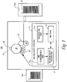
- FIG. 1 is a schematic view illustrating an image forming apparatus such as a liquid electrophotography system (LEP) according to an example.
- an image forming apparatus 100 includes an image forming unit 12 that receives media S from an input unit 14a and outputs the media S to an output unit 14b.
- the image forming unit 12 includes an ink applicator unit 13 and a photoconductive member 18 on which images can be formed.
- the photoconductive member 18 may be charged with a suitable charger (not illustrated) such as a charge roller. Portions of the outer surface of the photoconductive member 18 that correspond to features of the image can be selectively discharged by a laser writing unit 16 to form an electrostatic and/or latent image thereon.
- the image forming apparatus 100 also includes an ink delivery system 11 including an imaging oil unit 11a, an ink consumable unit 11b, at least one ink tank 10, and at least one intermediate reservoir 17.
- the ink applicator unit 13 may include one BID.
- the ink applicator unit 13 may include a plurality of BIDs in which each BID may correspond to a respective color ink such as black ink, cyan ink, yellow ink, and magenta ink.
- the image forming apparatus 100 may include a plurality of ink tanks and a plurality of intermediate reservoirs corresponding therewith.
- one ink tank 10 and one corresponding intermediate reservoir 17 may correspond to each BID applying a different color ink.
- the imaging oil unit 11a may supply imaging oil such as Isopar trademarked by Exxon Corporation to the ink tank 10.
- the ink consumable unit 11b may supply concentrated ink such as concentrated liquid toner to the intermediate reservoir 17, for example, to maintain a predetermined amount of ink density of the ink therein.
- the intermediate reservoir 17 may receive ink from the ink tank 10, for example, when the ink tank 10, in response to receiving an amount of ink from the intermediate reservoir 17 to increase ink density of the ink in the ink tank 10, back flows an amount of ink approximately equal to the amount of ink received from the intermediate reservoir 17 to the intermediate reservoir 17.
- the intermediate reservoir 17 may provide ink to the ink tank 10, for example, when the ink density of the ink in the ink tank 10 is less than a predetermined ink tank ink density.
- the ink tank 10 may supply ink such as liquid toner, for example, ElectroInk, trademarked by Hewlett-Packard Company, to an ink applicator unit 13.
- the ink applicator unit 13 applies the ink such as liquid toner to the electrostatic and/or latent image to form an ink image on the photoconductive member 18 to be transferred to an intermediate transfer member (ITM) 15.
- ITM 15 is configured to receive the ink image from the photoconductive member 18 and transfer the ink image to the media S.
- the media S is pinched between the ITM 15 and an impression member 19. Once the ink image has been transferred to the media S, the media S can be transported to the output unit 14b.
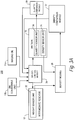
- FIG. 2 is a block diagram illustrating an image forming apparatus usable with an ink applicator unit according to an example.
- An ink applicator unit 13 may include an inkjet print head, BID as previously disclosed with respect to FIG. 1 , and the like.
- FIG. 3A is a schematic view illustrating the image forming apparatus of FIG. 2 according to an example.
- the image forming apparatus 200 usable with an ink applicator unit 13 includes an ink consumable unit 11b, an ink tank 10 including a density sensor unit 24, an intermediate reservoir 17 including a weight sensor unit 22, and a density module 26.
- the image forming apparatus 200 may include a plurality of corresponding sets of ink tanks and intermediate reservoirs (not illustrated).
- an image forming apparatus 200 may be a digital copier, printer, bookmaking machine, facsimile machine, multi-function machine, and the like.
- the ink consumable unit 11b is configured to store a consumable ink therein.
- the consumable ink may include a high solid ink concentrate such as concentrated liquid toner.
- the concentrated liquid toner has a consumable ink density of about 40%. That is, the ink density may be represented as a percentage corresponding to a mass of ink solids in a solution divided by total solution mass.
- the imaging oil unit 11a may supply imaging oil to the ink tank 10.
- the ink tank 10 is configured to store ink therein and to selectively provide the ink 10 to the ink applicator unit 13.
- the amount of ink supplied to the ink applicator unit 13 and/or the ink density of the ink in the ink tank 10 may vary due to a number of printed images formed by the ink applicator unit 13 and an amount of corresponding printed ink cover applied on the media therefrom.
- the density sensor unit 24 is disposed in the ink tank 10.
- the density sensor unit 24 is configured to identify a first ink density of the ink in the ink tank 10.
- a predetermined ink tank ink density of the ink in the ink tank 10 may be about 4.5%. That is, the ink density may be represented as a percentage corresponding to a mass of ink solids in a solution divided by total solution mass.
- the intermediate reservoir 17 is configured to store ink therein.
- the intermediate reservoir 17 is selectively in fluid communication with the ink consumable unit 11b and the ink tank 10.
- fluid communication may be established through a density control module 38 to control the flow of ink between the intermediate reservoir 17 and the ink consumable unit 10b, between the intermediate reservoir 17 and the ink tank 10, and/or between the imaging oil unit 11a and the ink tank 10.
- a second ink density of the ink in the intermediate reservoir 17 may be determined and, for example, used to maintain the ink therein.
- the predetermined reservoir ink density may be about 16%.
- the ink density may be represented as a percentage corresponding to a mass of ink solids in a solution divided by total solution mass.
- the weight sensor unit 22 is configured to identify an ink weight of the ink in the intermediate reservoir 17.
- the weight sensor unit 22 may be disposed in contact with the intermediate reservoir 17.
- the weight sensor unit 22 may be in a form of a load cell disposed in contact with an exterior surface of the intermediate reservoir 17 to determine the weight of the ink in the intermediate reservoir 17.
- the weight sensor unit 17 may be in contact with an internal surface of the intermediate reservoir 17.
- the density module 26 is configured to determine the second ink density of the ink in the intermediate reservoir 17 based at least on the identified first ink density and the identified ink weight of the ink in the intermediate reservoir 17. For example, the density module 26 may determine the second ink density by calculating a derivative of an ink density of the ink in the ink tank with respect to a weight change of the ink in the intermediate reservoir 17 before and after a corresponding ink density correction to the ink in the ink tank 10 and correlating the derivative to the second ink density of the ink in the intermediate reservoir 17.
- the ink density correction may be changing the ink density of the ink in the ink tank 10 by providing ink from the ink reservoir to the ink tank.
- calculation of the derivative may include using a first ink density of the ink in the ink tank 10 before an ink density correction is performed to the ink in the ink tank 10 and a second ink density of the ink in the ink tank 10 achieved as a result of the ink density correction performed to the ink in the ink tank 10.
- the density module 26 may determine the second ink density by correlating the calculated derivative to the second ink density of the ink in the intermediate reservoir 17.
- the derivative of the ink density of the ink in the ink tank 10 may be represented by a corresponding equation such as Equation 1 identified below.
- D it d it 2 ⁇ d it 1 / w ir 2 ⁇ w ir 1 ,
- the density module 26 may be implemented in hardware, software, or in a combination of hardware and software.
- the density module 26 may include a set of density machine-readable instructions to determine the second ink density of the ink in the intermediate reservoir 17 which may include, for example, calculating a derivative such as Equation 1, and correlating the calculated derivative.
- the density module 26 may be implemented in whole or in part as a computer program such as the set of density machine-readable instructions stored in the image forming apparatus 200 locally or remotely.
- the computer program may be stored in a memory such as a server or a host computing device 50 ( FIG. 5 ) considered herein, in examples, as part of the image forming apparatus 200.
- FIG. 3B is a schematic view illustrating the image forming apparatus of FIG. 3A including a density control module according to an example.
- the image forming apparatus 200 may also include a density control module 38, a density comparison module 37, a quantity sensor unit 34, and a quantity comparison module 39.
- the density control module 38 is configured to increase the first ink density and increase the second ink density.
- the density control module 38 may selectively establish fluid communication between the ink tank 10 and the intermediate reservoir 17.
- the ink in the intermediate reservoir 17 may have a second ink density thereof greater than the first ink density and an amount of the ink may flow from the intermediate reservoir 17 to the ink tank 10.
- the establishment of such ink flow may be in response to determination by the density comparison module 37 that an identified first ink density is less than a predetermined ink tank ink density.
- the density control module 38 may also selectively establish fluid communication between the intermediate reservoir 17 and the ink consumable unit 10b.
- the consumable ink in the ink consumable unit 10b may have a predetermined consumable ink density greater than the second ink density and the consumable ink may flow from the ink consumable unit 10b to the intermediate reservoir 17.
- the establishment of such ink flow may be in response to the determination by the density comparison module 37 that the determined second ink density is less than the predetermined reservoir ink density.
- the density control module 38 may be implemented in hardware, software, or in a combination of hardware and software.
- the density control module 38 may include one or more programmable valves 38a and 38b, pumps such as a two-way pump 38c, and the like, to control fluid communication between the ink tank 10, the intermediate reservoir 17, the ink consumable unit 10b, and/or the imaging oil unit 10a.
- programmable valve 38a may selectively open and close to control consumable ink flow from the ink consumable unit 10b to the intermediate reservoir 17.
- programmable valve 38b may selectively open and close to control imaging oil flow from the imaging oil unit 10a to the ink tank 10.
- the two-way pump 38c may selectively be turned on to control ink flow (e.g., fluid communication) between the ink tank 10 and the intermediate reservoir 17.
- the two-way pump 38c may be disposed between the ink tank 10 and the intermediate reservoir 17.
- the two-way pump 38c is configured to selectively provide a direction of fluid communication between the intermediate reservoir 17 and the ink tank 10 established by the two-way pump 38c.
- the density comparison module 37 is configured to determine whether the identified first ink density is less than the predetermined ink tank ink density.
- the density comparison module 37 is configured to also identify whether the determined second ink density is less than a predetermined reservoir ink density of the ink in the intermediate reservoir 17.
- the predetermined reservoir ink density is greater than the predetermined ink tank ink density.
- the predetermined reservoir ink density is also less than a predetermined consumable ink density of the consumable ink in the ink consumable unit 10b.
- the density comparison module 37 may be implemented in hardware, software, or in a combination of hardware and software.
- the density comparison module 37 may include a set of density comparison machine-readable instructions. The set of density comparison machine-readable instructions may compare the identified first ink density and the predetermined ink tank ink density to determine whether the identified first ink density is less than the predetermined ink tank ink density.
- the set of density comparison machine-readable instructions may also compare the determined second ink density and the predetermined reservoir ink density to determine whether the second ink density is less than the predetermined reservoir ink density.
- the set of density comparison machine-readable instructions may initiate the opening and closing of the programmable valves 38a and 38b based on the respective determinations thereof.
- the density comparison module 37 may be implemented in whole or in part as a computer program such as a set of density comparison machine-readable instructions stored in the image forming apparatus 200 locally or remotely.
- the computer program may be stored in a memory such as a server or a host computing device 50 considered herein as part of the image forming apparatus 200.
- the image forming apparatus 200 may also include a quantity sensor unit 34 disposed in contact with the ink tank 10. That is, the quantity sensor unit 34 may in contact with an external surface or an internal surface of the ink tank 10.
- the quantity sensor unit 34 may be configured to identify an amount of ink in the ink tank 10. In examples, the identified amount may be represented as a volume, weight, capacity level, and the like.
- the quantity sensor unit 34 for example, may be a load cell disposed outside of the ink tank 10 to weight the weight of the ink in the ink tank 10.
- the quantity comparison module 39 is configured to determine whether the identified amount of ink in the ink tank is at least one of equal to and less than a predetermined lower tank limit.
- the quantity comparison module 39 may also determine whether an amount of the ink in the intermediate reservoir is at least one of equal to and greater than a predetermined upper reservoir limit. In examples, the quantity comparison module 39 may also determine whether the identified amount of ink in the ink tank 10 is at least one of equal to and greater than a predetermined upper tank limit and whether the identified amount of ink in the intermediate reservoir 17 is at least one of equal to and lower than a predetermined lower reservoir limit.
- the predetermined upper tank limit may correspond to a desired maximum amount of ink to be stored in the ink tank 10.
- the predetermined lower tank limit may correspond to a desired minimum amount of ink to be stored in the ink tank 10.
- the predetermined upper reservoir limit may correspond to a desired maximum amount of ink to be stored in the intermediate reservoir 17.
- the predetermined lower reservoir limit may correspond to a desired minimum amount of ink to be stored in the intermediate reservoir 17.
- the predetermined upper tank limit, the predetermined lower tank limit, the predetermined upper reservoir limit, and the predetermined lower reservoir limit may be stored in a look-up table.
- various paths of fluid communication may be established. For example, based on the determination that the ink in the ink tank 10 has not reached the lower tank limit, fluid communication is established from the imaging oil unit 11a to the ink tank 10 to at least increase the ink level in the ink tank 10.
- the quantity comparison module 39 may be implemented in hardware, software, or in a combination of hardware and software.
- the quantity comparison module 39 may include a set of quantity comparison machine-readable instructions.
- the set of quantity comparison machine-readable instructions may compare the identified amount of ink in the ink tank 10 with the predetermined upper tank limit and/or the predetermined lower tank limit.
- the set of quantity comparison machine-readable instructions may also determine whether the identified amount of ink in the ink tank 10 is at least one of equal to and greater than a predetermined upper tank limit and/or whether the identified amount of ink in the ink tank 10 is at least one of equal to and less than a predetermined lower tank limit.
- the set of quantity comparison machine-readable instructions may also determine whether an amount of the ink in the intermediate reservoir 17 is at least one of equal to and greater than a predetermined upper reservoir limit and/or whether an amount of the ink in the intermediate reservoir 17 is at least one of equal to and less than a predetermined lower reservoir limit.
- the quantity comparison module 39 may be implemented in whole or in part as a computer program such as a set of quantity comparison machine-readable instructions stored in the image forming apparatus 200 locally or remotely.
- the computer program may be stored in a memory such as a server or a host computing device 50 considered herein as part of the image forming apparatus 200.
- FIG. 4 is a flowchart illustrating an ink density control method of an image forming apparatus according to an example.
- ink is stored in an ink tank of an image forming apparatus to be selectively provided to an ink applicator unit to form images on media.
- ink is stored in an intermediate reservoir of the image forming apparatus.
- a first ink density of the ink in the ink tank is identified by a density sensor unit disposed in the ink tank.
- an ink weight of the ink in the intermediate reservoir is identified by a weight sensor unit.
- a second ink density is determined based at least on the identified first ink density by the density sensor unit and the identified ink weight of the ink in the intermediate reservoir by the weight sensor unit.
- the weight sensor unit for example, is disposed in contact with the intermediate reservoir.
- the determination of the second ink density may include calculating a derivative of an ink density of the ink in the ink tank with respect to a weight change of the ink in the intermediate reservoir before and after a corresponding ink density correction to the ink in the ink tank, and correlating the calculated derivative to the second ink density.
- the ink density control method may also include determining whether the identified first ink density is less than a predetermined ink tank ink density, and increasing the identified first ink density in response to the determination of the identified first ink density that is less than the predetermined ink tank ink density. For example, increasing the identified first ink density may include selectively establishing fluid communication between the ink tank and the intermediate reservoir such that an amount of the ink in the intermediate reservoir flows from the intermediate reservoir to the ink tank.
- the ink in the intermediate reservoir may have a second ink density thereof greater than the identified first ink density.
- the ink density control method may also include back flowing an amount of ink in the ink tank to the intermediate reservoir approximately equal to the amount of the ink received by the ink tank from the intermediate reservoir in response to the amount of the ink from the intermediate reservoir flowing into the ink tank.
- the ink density control method may also include a selection of the direction of fluid communication between the intermediate reservoir and the ink tank established by a two-way pump disposed therebetween.
- establishment of a fluid communication between the intermediate reservoir and the ink tank by a two-way pump disposed therebetween based on a selection of a direction of fluid communication may be in response to the determination of the identified first ink density of at least one of equal to and greater than the predetermined upper ink tank ink density by the density comparison module 37.
- establishment of a fluid communication between the intermediate reservoir and the ink tank by a two-way pump disposed therebetween based on a selection of a direction of fluid communication may be in response to the determination of the identified first ink density that is at least one of equal to and greater than the predetermined upper ink tank ink density by the density comparison module 37.
- establishment of a fluid communication between the intermediate reservoir and the ink tank by a two-way pump disposed therebetween based on a selection of a direction of fluid communication may be in response to the determination of the identified first ink density at least one of equal to and less than the predetermined lower ink tank ink density by the density comparison module 37.
- the ink density control method may also include a determination of whether the second ink density is less than a predetermined reservoir ink density, and an increase to the second ink density to the predetermined reservoir ink density in response to the determination of the second ink density that is less than the predetermined reservoir ink density.
- the increase to the second ink density of the ink in the intermediate reservoir may include selectively establishing fluid communication between the intermediate reservoir and an ink consumable unit of the image forming apparatus such that a consumable ink flows from the ink consumable unit to the intermediate reservoir.
- the consumable ink in the ink consumable unit may have a consumable ink density greater than the second ink density.
- the ink density control method may also include identification of an amount of the ink in the ink tank by a quantity sensor unit, and a determination of whether the identified amount of ink in the ink tank is at least one of equal to and greater than a predetermined upper tank limit by a quantity comparison module.
- the ink density control method may also include maintaining a reservoir ink amount in the intermediate reservoir within a predetermined reservoir amount range and an ink tank ink amount in the ink tank within a predetermined ink tank amount range by the density control module. The maintaining may be based on the determination of the identified amount of the ink in the ink tank that is at least one of equal to and greater than the predetermined upper tank limit by the quantity comparison module.
- the ink density control method may also include selection of a direction of fluid communication between the intermediate reservoir and the ink tank established by a two-way pump disposed therebetween.
- FIG. 5 is a block diagram of the method of FIG. 4 embodied in a computer-readable storage medium according to an example.
- the present disclosure may be embodied in any computer-readable storage medium 55 for use by or in connection with an instruction-execution system, apparatus or device such as a computer/processor based system, processor 59 or other system (e.g., computing device 50) that can fetch the instructions from the instruction-execution system, apparatus or device, and execute the instructions 57 contained therein.
- a computer-readable storage medium 55 can store, communicate, propagate or transport instructions 57 for use by or in connection with the computing device 50 such as an image forming apparatus 200.
- the computer-readable storage medium 55 can include any one of many physical media such as, for example, electronic, magnetic, optical, electromagnetic, infrared, or semiconductor media.
- Computer-readable storage medium 55 would include, but are not limited to, a portable magnetic computer diskette such as floppy diskettes or hard drives, a random access memory (RAM), a read-only memory (ROM), an erasable programmable read-only memory, or a portable compact disc. It is to be understood that the computer-readable storage medium 55 could even be paper or another suitable medium upon which the instructions 57 are printed, as the instructions 57 can be electronically captured, via, for instance, optical scanning of the paper or other medium, then compiled, interpreted or otherwise processed in a single manner, if necessary, and then stored therein.
- the computer-readable storage medium 55 includes instructions 57 executed, for example, by the processor 59 and, that when executed, cause the processor 59 and/or computing device 50 to perform some or all of the functionality described herein.
- each block may represent a module, segment, or portion of code that includes one or more executable instructions to implement the specified logical function(s).
- each block may represent a circuit or a number of interconnected circuits to implement the specified logical function(s).
- the flowchart of FIG. 4 illustrates a specific order of execution, the order of execution may differ from that which is depicted. For example, the order of execution of two or more blocks may be scrambled relative to the order illustrated. Also, two or more blocks illustrated in succession in FIG. 4 may be executed concurrently or with partial concurrence. All such variations are within the scope of the present disclosure.
Landscapes
- Physics & Mathematics (AREA)
- General Physics & Mathematics (AREA)
- Engineering & Computer Science (AREA)
- Quality & Reliability (AREA)
- Ink Jet (AREA)
Description
- Image forming apparatuses such as a liquid electrophotography printing apparatus includes providing ink such as liquid toner to an ink applicator unit such as binary ink developers. The ink applicator unit provides charged liquid toner to a latent image on a photoconductive member to form ink images. The photoconductive member transfers the ink images onto an image transfer member and/or media.
-
US2008181671 discloses a liquid separator, liquid supplying system and image forming apparatus. A level detector detects a volume of the liquid in a developer adjusting device containing residual developer. Toner from a toner tank can be fed into the adjusting device to increase the toner density for feeding into the developing device via the developer reserve tank. There is no mention of overflow. -
US2008317490 discloses a liquid developer concentration adjustment system wherein the toner density is measured in known ways, such as the measurement of the viscosity, but also by detecting the weight in developer concentration adjusting apparatus. The density of the developer in the toner tank is not measured. Overflow is involved in the process. -
US5923930 discloses a density sensor in a developing liquid tank and a high-density developing liquid tank for adding to the developing liquid tank. There is no mention of overcoming the problem of overflow. - Non-limiting examples of the present disclosure are described in the following description, read with reference to the figures attached hereto and do not limit the scope of the claims. In the figures, identical and similar structures, elements or parts thereof that appear in more than one figure are generally labeled with the same or similar references in the figures in which they appear. Dimensions of components and features illustrated in the figures are chosen primarily for convenience and clarity of presentation and are not necessarily to scale. Referring to the attached figures:
-
FIG. 1 is a schematic view illustrating an image forming apparatus such as a liquid electrophotography printing apparatus according to an example. -
FIG. 2 is a block diagram illustrating an image forming apparatus usable with an ink applicator unit according to an example. -
FIG. 3A is a schematic view illustrating the image forming apparatus ofFIG. 2 according to an example. -
FIG. 3B is a schematic view illustrating the image forming apparatus ofFIG. 3A including a density control module according to an example. -
FIG. 4 is a flowchart illustrating an ink density control method of an image forming apparatus according to an example. -
FIG. 5 is a block diagram of the ink density control method ofFIG. 4 embodied in a computer-readable storage medium according to an example. - In the following detailed description, reference is made to the accompanying drawings which form a part hereof, and in which is depicted by way of illustration specific examples in which the present disclosure may be practiced. It is to be understood that other examples may be utilized and structural or logical changes may be made without departing from the scope of the present disclosure. The following detailed description, therefore, is not to be taken in a limiting sense, and the scope of the present disclosure is defined by the appended claims.
- Image forming apparatuses such as a liquid electrophotography printing apparatus (LEP) provides ink such as liquid toner and carrier fluid such as imaging oil from an ink tank to an ink applicator unit such as binary ink developers (BIDs). The liquid toner is charged and is provided to a latent image on a photoconductive member such as a photo imaging member (PIP) to form an ink image, for example, by BIDs. The photoconductive member, in turn, provides the image to an intermediate transfer member such as an image transfer blanket. The image transfer blanket transfers the image onto media. The ink density (e.g., ink solids density, concentrated ink solids density, and the like) and an amount of ink in the ink tank, however, may fluctuate beyond an acceptable range and/or value. Accordingly, maintaining control of the quantity and ink density of the ink in the ink tank may be adversely impacted. Consequently, overflows may occur due to a large amount of printed ink cover applied on the media in forming images thereon. Additionally, ink density control may be adversely impacted during ink consumable unit replacement.
- In examples, an ink density control method of an image forming apparatus includes, among other things, identifying a first ink density of ink in an ink tank by a density sensor unit disposed in an ink tank, and identifying an ink weight of ink in an intermediate reservoir by a weight sensor unit. The ink density control method may also include determining a second ink density of the ink in the intermediate reservoir based at least on the identified first ink density by the density sensor unit and the identified ink weight by the weight sensor unit. In examples, the ink density control method may also include back flowing an amount of ink in the ink tank to the intermediate reservoir approximately equal to the amount of the ink received by the ink tank from the intermediate reservoir in response to the amount of the ink from the intermediate reservoir flowing into the ink tank.
- Thus, the intermediate reservoir may be used as a buffer even while an ink consumable unit is being replaced. Accordingly, control of the quantity and ink density of the ink in the ink tank and intermediate reservoir may be maintained even during ink consumable unit replacement. Thus, overflowing of at least the ink tank due to a large amount of printed ink cover applied on the media in forming images thereon may be reduced. Further, respective ink density of the ink in the ink tank and the intermediate reservoir may be determined based on a density sensor unit disposed in the ink tank.
-
FIG. 1 is a schematic view illustrating an image forming apparatus such as a liquid electrophotography system (LEP) according to an example. Referring toFIG. 1 , animage forming apparatus 100 includes animage forming unit 12 that receives media S from aninput unit 14a and outputs the media S to anoutput unit 14b. Theimage forming unit 12 includes anink applicator unit 13 and aphotoconductive member 18 on which images can be formed. Thephotoconductive member 18 may be charged with a suitable charger (not illustrated) such as a charge roller. Portions of the outer surface of thephotoconductive member 18 that correspond to features of the image can be selectively discharged by alaser writing unit 16 to form an electrostatic and/or latent image thereon. Theimage forming apparatus 100 also includes anink delivery system 11 including animaging oil unit 11a, an inkconsumable unit 11b, at least oneink tank 10, and at least oneintermediate reservoir 17. - In examples, the
ink applicator unit 13 may include one BID. In other examples, theink applicator unit 13 may include a plurality of BIDs in which each BID may correspond to a respective color ink such as black ink, cyan ink, yellow ink, and magenta ink. Accordingly, theimage forming apparatus 100 may include a plurality of ink tanks and a plurality of intermediate reservoirs corresponding therewith. Thus, oneink tank 10 and one correspondingintermediate reservoir 17 may correspond to each BID applying a different color ink. Theimaging oil unit 11a may supply imaging oil such as Isopar trademarked by Exxon Corporation to theink tank 10. The inkconsumable unit 11b may supply concentrated ink such as concentrated liquid toner to theintermediate reservoir 17, for example, to maintain a predetermined amount of ink density of the ink therein. Theintermediate reservoir 17 may receive ink from theink tank 10, for example, when theink tank 10, in response to receiving an amount of ink from theintermediate reservoir 17 to increase ink density of the ink in theink tank 10, back flows an amount of ink approximately equal to the amount of ink received from theintermediate reservoir 17 to theintermediate reservoir 17. Theintermediate reservoir 17 may provide ink to theink tank 10, for example, when the ink density of the ink in theink tank 10 is less than a predetermined ink tank ink density. - Referring to
FIG. 1 , theink tank 10 may supply ink such as liquid toner, for example, ElectroInk, trademarked by Hewlett-Packard Company, to anink applicator unit 13. Theink applicator unit 13 applies the ink such as liquid toner to the electrostatic and/or latent image to form an ink image on thephotoconductive member 18 to be transferred to an intermediate transfer member (ITM) 15. The ITM 15 is configured to receive the ink image from thephotoconductive member 18 and transfer the ink image to the media S. During the transfer of the ink image from theITM 15 to the media S, the media S is pinched between theITM 15 and animpression member 19. Once the ink image has been transferred to the media S, the media S can be transported to theoutput unit 14b. -
FIG. 2 is a block diagram illustrating an image forming apparatus usable with an ink applicator unit according to an example. Anink applicator unit 13, for example, may include an inkjet print head, BID as previously disclosed with respect toFIG. 1 , and the like.FIG. 3A is a schematic view illustrating the image forming apparatus ofFIG. 2 according to an example. Referring toFIGS. 2 and3A , in examples, theimage forming apparatus 200 usable with anink applicator unit 13 includes anink consumable unit 11b, anink tank 10 including adensity sensor unit 24, anintermediate reservoir 17 including aweight sensor unit 22, and adensity module 26. In examples, theimage forming apparatus 200 may include a plurality of corresponding sets of ink tanks and intermediate reservoirs (not illustrated). In examples, animage forming apparatus 200 may be a digital copier, printer, bookmaking machine, facsimile machine, multi-function machine, and the like. - The
ink consumable unit 11b is configured to store a consumable ink therein. For example, the consumable ink may include a high solid ink concentrate such as concentrated liquid toner. In examples, the concentrated liquid toner has a consumable ink density of about 40%. That is, the ink density may be represented as a percentage corresponding to a mass of ink solids in a solution divided by total solution mass. Theimaging oil unit 11a may supply imaging oil to theink tank 10. Theink tank 10 is configured to store ink therein and to selectively provide theink 10 to theink applicator unit 13. The amount of ink supplied to theink applicator unit 13 and/or the ink density of the ink in theink tank 10 may vary due to a number of printed images formed by theink applicator unit 13 and an amount of corresponding printed ink cover applied on the media therefrom. Thedensity sensor unit 24 is disposed in theink tank 10. Thedensity sensor unit 24 is configured to identify a first ink density of the ink in theink tank 10. In examples, a predetermined ink tank ink density of the ink in theink tank 10 may be about 4.5%. That is, the ink density may be represented as a percentage corresponding to a mass of ink solids in a solution divided by total solution mass. - Referring to
FIGS. 2 and3A , in examples, theintermediate reservoir 17 is configured to store ink therein. Theintermediate reservoir 17 is selectively in fluid communication with theink consumable unit 11b and theink tank 10. For example, fluid communication may be established through adensity control module 38 to control the flow of ink between theintermediate reservoir 17 and the ink consumable unit 10b, between theintermediate reservoir 17 and theink tank 10, and/or between theimaging oil unit 11a and theink tank 10. A second ink density of the ink in theintermediate reservoir 17 may be determined and, for example, used to maintain the ink therein. In examples, the predetermined reservoir ink density may be about 16%. That is, the ink density may be represented as a percentage corresponding to a mass of ink solids in a solution divided by total solution mass. Theweight sensor unit 22 is configured to identify an ink weight of the ink in theintermediate reservoir 17. In examples, theweight sensor unit 22 may be disposed in contact with theintermediate reservoir 17. For example, theweight sensor unit 22 may be in a form of a load cell disposed in contact with an exterior surface of theintermediate reservoir 17 to determine the weight of the ink in theintermediate reservoir 17. In examples, theweight sensor unit 17 may be in contact with an internal surface of theintermediate reservoir 17. - Referring to
FIGS. 2 and3A , in examples, thedensity module 26 is configured to determine the second ink density of the ink in theintermediate reservoir 17 based at least on the identified first ink density and the identified ink weight of the ink in theintermediate reservoir 17. For example, thedensity module 26 may determine the second ink density by calculating a derivative of an ink density of the ink in the ink tank with respect to a weight change of the ink in theintermediate reservoir 17 before and after a corresponding ink density correction to the ink in theink tank 10 and correlating the derivative to the second ink density of the ink in theintermediate reservoir 17. The ink density correction, for example, may be changing the ink density of the ink in theink tank 10 by providing ink from the ink reservoir to the ink tank. In examples, calculation of the derivative may include using a first ink density of the ink in theink tank 10 before an ink density correction is performed to the ink in theink tank 10 and a second ink density of the ink in theink tank 10 achieved as a result of the ink density correction performed to the ink in theink tank 10. Additionally, thedensity module 26 may determine the second ink density by correlating the calculated derivative to the second ink density of the ink in theintermediate reservoir 17. - In examples, the derivative of the ink density of the ink in the
ink tank 10 may be represented by a corresponding equation such as Equation 1 identified below.
- Dit corresponds to a derivative of an ink density of ink in an
ink tank 10; - dit1 corresponds to an identified first ink density of the ink in the
ink tank 10 before an ink density correction is performed to the ink in the ink tank 10 (e.g., increasing the identified first ink density of the ink in the ink tank 10); - dit2 corresponds to the second ink density of the ink in the
ink tank 10 achieved as a result of the ink density correction performed to the ink in theink tank 10; - wir1 corresponds to an identified ink weight of ink in an
intermediate reservoir 17 before the ink density correction is performed to the ink in theink tank 10; and - wir2 corresponds to the identified ink weight of the ink in the
intermediate reservoir 17 after the ink density correction is performed to the ink in theink tank 10. - In examples, the
density module 26 may be implemented in hardware, software, or in a combination of hardware and software. For example, thedensity module 26 may include a set of density machine-readable instructions to determine the second ink density of the ink in theintermediate reservoir 17 which may include, for example, calculating a derivative such as Equation 1, and correlating the calculated derivative. In examples, thedensity module 26 may be implemented in whole or in part as a computer program such as the set of density machine-readable instructions stored in theimage forming apparatus 200 locally or remotely. For example, the computer program may be stored in a memory such as a server or a host computing device 50 (FIG. 5 ) considered herein, in examples, as part of theimage forming apparatus 200. -
FIG. 3B is a schematic view illustrating the image forming apparatus ofFIG. 3A including a density control module according to an example. Referring toFIGS. 3A and3B , in examples, theimage forming apparatus 200 may also include adensity control module 38, adensity comparison module 37, aquantity sensor unit 34, and aquantity comparison module 39. In examples, thedensity control module 38 is configured to increase the first ink density and increase the second ink density. For example, thedensity control module 38 may selectively establish fluid communication between theink tank 10 and theintermediate reservoir 17. - In examples, the ink in the
intermediate reservoir 17 may have a second ink density thereof greater than the first ink density and an amount of the ink may flow from theintermediate reservoir 17 to theink tank 10. The establishment of such ink flow may be in response to determination by thedensity comparison module 37 that an identified first ink density is less than a predetermined ink tank ink density. For example, thedensity control module 38 may also selectively establish fluid communication between theintermediate reservoir 17 and the ink consumable unit 10b. The consumable ink in the ink consumable unit 10b may have a predetermined consumable ink density greater than the second ink density and the consumable ink may flow from the ink consumable unit 10b to theintermediate reservoir 17. The establishment of such ink flow may be in response to the determination by thedensity comparison module 37 that the determined second ink density is less than the predetermined reservoir ink density. - In examples, the
density control module 38 may be implemented in hardware, software, or in a combination of hardware and software. For example, thedensity control module 38 may include one or moreprogrammable valves way pump 38c, and the like, to control fluid communication between theink tank 10, theintermediate reservoir 17, the ink consumable unit 10b, and/or the imaging oil unit 10a. In examples,programmable valve 38a may selectively open and close to control consumable ink flow from the ink consumable unit 10b to theintermediate reservoir 17. For example,programmable valve 38b may selectively open and close to control imaging oil flow from the imaging oil unit 10a to theink tank 10. Additionally, the two-way pump 38c, for example, may selectively be turned on to control ink flow (e.g., fluid communication) between theink tank 10 and theintermediate reservoir 17. The two-way pump 38c may be disposed between theink tank 10 and theintermediate reservoir 17. In examples, the two-way pump 38c is configured to selectively provide a direction of fluid communication between theintermediate reservoir 17 and theink tank 10 established by the two-way pump 38c. - Referring to
FIGS. 3A and3B , in examples, thedensity comparison module 37 is configured to determine whether the identified first ink density is less than the predetermined ink tank ink density. Thedensity comparison module 37 is configured to also identify whether the determined second ink density is less than a predetermined reservoir ink density of the ink in theintermediate reservoir 17. In examples, the predetermined reservoir ink density is greater than the predetermined ink tank ink density. Additionally, the predetermined reservoir ink density is also less than a predetermined consumable ink density of the consumable ink in the ink consumable unit 10b. In examples, thedensity comparison module 37 may be implemented in hardware, software, or in a combination of hardware and software. For example, thedensity comparison module 37 may include a set of density comparison machine-readable instructions. The set of density comparison machine-readable instructions may compare the identified first ink density and the predetermined ink tank ink density to determine whether the identified first ink density is less than the predetermined ink tank ink density. - The set of density comparison machine-readable instructions may also compare the determined second ink density and the predetermined reservoir ink density to determine whether the second ink density is less than the predetermined reservoir ink density. The set of density comparison machine-readable instructions may initiate the opening and closing of the
programmable valves density comparison module 37 may be implemented in whole or in part as a computer program such as a set of density comparison machine-readable instructions stored in theimage forming apparatus 200 locally or remotely. For example, the computer program may be stored in a memory such as a server or ahost computing device 50 considered herein as part of theimage forming apparatus 200. - In examples, the
image forming apparatus 200 may also include aquantity sensor unit 34 disposed in contact with theink tank 10. That is, thequantity sensor unit 34 may in contact with an external surface or an internal surface of theink tank 10. Thequantity sensor unit 34 may be configured to identify an amount of ink in theink tank 10. In examples, the identified amount may be represented as a volume, weight, capacity level, and the like. Thequantity sensor unit 34, for example, may be a load cell disposed outside of theink tank 10 to weight the weight of the ink in theink tank 10. Referring toFIGS. 3A and3B , in examples, thequantity comparison module 39 is configured to determine whether the identified amount of ink in the ink tank is at least one of equal to and less than a predetermined lower tank limit. Thequantity comparison module 39 may also determine whether an amount of the ink in the intermediate reservoir is at least one of equal to and greater than a predetermined upper reservoir limit. In examples, thequantity comparison module 39 may also determine whether the identified amount of ink in theink tank 10 is at least one of equal to and greater than a predetermined upper tank limit and whether the identified amount of ink in theintermediate reservoir 17 is at least one of equal to and lower than a predetermined lower reservoir limit. - The predetermined upper tank limit may correspond to a desired maximum amount of ink to be stored in the
ink tank 10. The predetermined lower tank limit may correspond to a desired minimum amount of ink to be stored in theink tank 10. The predetermined upper reservoir limit may correspond to a desired maximum amount of ink to be stored in theintermediate reservoir 17. The predetermined lower reservoir limit may correspond to a desired minimum amount of ink to be stored in theintermediate reservoir 17. In examples, the predetermined upper tank limit, the predetermined lower tank limit, the predetermined upper reservoir limit, and the predetermined lower reservoir limit may be stored in a look-up table. In examples, based on at least one of the respective predetermined upper ink tank limit, the predetermined lower tank limit, the predetermined upper reservoir limit, and the predetermined lower reservoir limit determinations by the quantity comparison module, for example, various paths of fluid communication may be established. For example, based on the determination that the ink in theink tank 10 has not reached the lower tank limit, fluid communication is established from theimaging oil unit 11a to theink tank 10 to at least increase the ink level in theink tank 10. - In examples, the
quantity comparison module 39 may be implemented in hardware, software, or in a combination of hardware and software. For example, thequantity comparison module 39 may include a set of quantity comparison machine-readable instructions. The set of quantity comparison machine-readable instructions may compare the identified amount of ink in theink tank 10 with the predetermined upper tank limit and/or the predetermined lower tank limit. The set of quantity comparison machine-readable instructions may also determine whether the identified amount of ink in theink tank 10 is at least one of equal to and greater than a predetermined upper tank limit and/or whether the identified amount of ink in theink tank 10 is at least one of equal to and less than a predetermined lower tank limit. The set of quantity comparison machine-readable instructions may also determine whether an amount of the ink in theintermediate reservoir 17 is at least one of equal to and greater than a predetermined upper reservoir limit and/or whether an amount of the ink in theintermediate reservoir 17 is at least one of equal to and less than a predetermined lower reservoir limit. - In examples, the
quantity comparison module 39 may be implemented in whole or in part as a computer program such as a set of quantity comparison machine-readable instructions stored in theimage forming apparatus 200 locally or remotely. For example, the computer program may be stored in a memory such as a server or ahost computing device 50 considered herein as part of theimage forming apparatus 200. -
FIG. 4 is a flowchart illustrating an ink density control method of an image forming apparatus according to an example. In block S41, ink is stored in an ink tank of an image forming apparatus to be selectively provided to an ink applicator unit to form images on media. In block S42, ink is stored in an intermediate reservoir of the image forming apparatus. In block S43, a first ink density of the ink in the ink tank is identified by a density sensor unit disposed in the ink tank. In block S44, an ink weight of the ink in the intermediate reservoir is identified by a weight sensor unit. In block S45, a second ink density is determined based at least on the identified first ink density by the density sensor unit and the identified ink weight of the ink in the intermediate reservoir by the weight sensor unit. The weight sensor unit, for example, is disposed in contact with the intermediate reservoir. In examples, the determination of the second ink density may include calculating a derivative of an ink density of the ink in the ink tank with respect to a weight change of the ink in the intermediate reservoir before and after a corresponding ink density correction to the ink in the ink tank, and correlating the calculated derivative to the second ink density. - The ink density control method may also include determining whether the identified first ink density is less than a predetermined ink tank ink density, and increasing the identified first ink density in response to the determination of the identified first ink density that is less than the predetermined ink tank ink density. For example, increasing the identified first ink density may include selectively establishing fluid communication between the ink tank and the intermediate reservoir such that an amount of the ink in the intermediate reservoir flows from the intermediate reservoir to the ink tank. The ink in the intermediate reservoir may have a second ink density thereof greater than the identified first ink density. The ink density control method may also include back flowing an amount of ink in the ink tank to the intermediate reservoir approximately equal to the amount of the ink received by the ink tank from the intermediate reservoir in response to the amount of the ink from the intermediate reservoir flowing into the ink tank. The ink density control method may also include a selection of the direction of fluid communication between the intermediate reservoir and the ink tank established by a two-way pump disposed therebetween.
- In examples, establishment of a fluid communication between the intermediate reservoir and the ink tank by a two-way pump disposed therebetween based on a selection of a direction of fluid communication, for example, may be in response to the determination of the identified first ink density of at least one of equal to and greater than the predetermined upper ink tank ink density by the
density comparison module 37. In examples, establishment of a fluid communication between the intermediate reservoir and the ink tank by a two-way pump disposed therebetween based on a selection of a direction of fluid communication, for example, may be in response to the determination of the identified first ink density that is at least one of equal to and greater than the predetermined upper ink tank ink density by thedensity comparison module 37. In examples, establishment of a fluid communication between the intermediate reservoir and the ink tank by a two-way pump disposed therebetween based on a selection of a direction of fluid communication, for example, may be in response to the determination of the identified first ink density at least one of equal to and less than the predetermined lower ink tank ink density by thedensity comparison module 37. - The ink density control method may also include a determination of whether the second ink density is less than a predetermined reservoir ink density, and an increase to the second ink density to the predetermined reservoir ink density in response to the determination of the second ink density that is less than the predetermined reservoir ink density. For example, the increase to the second ink density of the ink in the intermediate reservoir may include selectively establishing fluid communication between the intermediate reservoir and an ink consumable unit of the image forming apparatus such that a consumable ink flows from the ink consumable unit to the intermediate reservoir. The consumable ink in the ink consumable unit may have a consumable ink density greater than the second ink density.
- The ink density control method may also include identification of an amount of the ink in the ink tank by a quantity sensor unit, and a determination of whether the identified amount of ink in the ink tank is at least one of equal to and greater than a predetermined upper tank limit by a quantity comparison module. The ink density control method may also include maintaining a reservoir ink amount in the intermediate reservoir within a predetermined reservoir amount range and an ink tank ink amount in the ink tank within a predetermined ink tank amount range by the density control module. The maintaining may be based on the determination of the identified amount of the ink in the ink tank that is at least one of equal to and greater than the predetermined upper tank limit by the quantity comparison module. The ink density control method may also include selection of a direction of fluid communication between the intermediate reservoir and the ink tank established by a two-way pump disposed therebetween.
-
FIG. 5 is a block diagram of the method ofFIG. 4 embodied in a computer-readable storage medium according to an example. Referring toFIG. 5 , in examples, the present disclosure may be embodied in any computer-readable storage medium 55 for use by or in connection with an instruction-execution system, apparatus or device such as a computer/processor based system,processor 59 or other system (e.g., computing device 50) that can fetch the instructions from the instruction-execution system, apparatus or device, and execute theinstructions 57 contained therein. In the context of this disclosure, a computer-readable storage medium 55 can store, communicate, propagate ortransport instructions 57 for use by or in connection with thecomputing device 50 such as animage forming apparatus 200. The computer-readable storage medium 55 can include any one of many physical media such as, for example, electronic, magnetic, optical, electromagnetic, infrared, or semiconductor media. - More specific examples of computer-
readable storage medium 55 would include, but are not limited to, a portable magnetic computer diskette such as floppy diskettes or hard drives, a random access memory (RAM), a read-only memory (ROM), an erasable programmable read-only memory, or a portable compact disc. It is to be understood that the computer-readable storage medium 55 could even be paper or another suitable medium upon which theinstructions 57 are printed, as theinstructions 57 can be electronically captured, via, for instance, optical scanning of the paper or other medium, then compiled, interpreted or otherwise processed in a single manner, if necessary, and then stored therein. The computer-readable storage medium 55 includesinstructions 57 executed, for example, by theprocessor 59 and, that when executed, cause theprocessor 59 and/orcomputing device 50 to perform some or all of the functionality described herein. - It is to be understood that the flowchart of
FIG. 4 illustrates an architecture, functionality, and operation of an example of the present disclosure. If embodied in software, each block may represent a module, segment, or portion of code that includes one or more executable instructions to implement the specified logical function(s). If embodied in hardware, each block may represent a circuit or a number of interconnected circuits to implement the specified logical function(s). Although the flowchart ofFIG. 4 illustrates a specific order of execution, the order of execution may differ from that which is depicted. For example, the order of execution of two or more blocks may be scrambled relative to the order illustrated. Also, two or more blocks illustrated in succession inFIG. 4 may be executed concurrently or with partial concurrence. All such variations are within the scope of the present disclosure. - The present disclosure has been described using non-limiting detailed descriptions of examples thereof and is not intended to limit the scope of the present disclosure. It should be understood that features and/or operations described with respect to one example may be used with other examples and that not all examples of the present disclosure have all of the features and/or operations illustrated in a particular figure or described with respect to one of the examples. Variations of examples described will occur to persons of the art. Furthermore, the terms "comprise," "include," "have" and their conjugates, shall mean, when used in the present disclosure and/or claims, "including but not necessarily limited to."
- It is noted that some of the above described examples may include structure, acts or details of structures and acts that may not be essential to the present disclosure and are intended to be exemplary. Therefore, the scope of the present disclosure is limited only by the elements and limitations as defined by the appended claims.
Claims (15)
- An ink density control method of an image forming apparatus (200), the ink density control method comprising:storing ink in an ink tank (10) of an image forming apparatus to be selectively provided to an ink applicator unit (13) to form images on media;storing consumable ink in an ink consumable unit (11b) of the image forming apparatus;storing ink in an intermediate reservoir (17) of the image forming apparatus;identifying a first ink density of the ink in the ink tank by a density sensor unit (24) disposed in the ink tank;identifying an ink weight of the ink in the intermediate reservoir by a weight sensor unit (22); anddetermining a second ink density of the ink in the intermediate reservoir based at least on the identified first ink density by the density sensor unit and the identified ink weight of the ink in the intermediate reservoir by the weight sensor unit, in order to allow control of the ink density in the ink tank and intermediate reservoir by selectively establishing fluid communication and a direction thereof between the intermediate reservoir and the ink tank and by selectively establishing fluid communication between the intermediate reservoir and the ink consumable unit.
- The ink density control method according to claim 1, further comprising:determining whether the identified first ink density is less than a predetermined ink tank (10) ink density; andincreasing the identified first ink density in response to the determination of the identified first ink density that is less than the predetermined ink tank ink density.
- The ink density control method according to claim 2, wherein the increasing the identified first ink density comprises:
selectively establishing fluid communication between the ink tank (10) and the intermediate reservoir (17) such that an amount of the ink in the intermediate reservoir having the second ink density thereof greater than the identified first ink density flows from the intermediate reservoir to the ink tank. - The ink density control method according to claim 3, further comprising:
back flowing an amount of ink in the ink tank (10) to the intermediate reservoir (17) approximately equal to the amount of the ink received by the ink tank from the intermediate reservoir in response to the amount of the ink from the intermediate reservoir flowing into the ink tank. - The ink density control method according to claim 3, further comprising:determining whether the second ink density is less than a predetermined reservoir ink density; andincreasing the second ink density in response to the determination of the second ink density that is less than the predetermined reservoir ink density.
- The ink density control method according to claim 5, wherein the increasing the second ink density comprises:
selectively establishing fluid communication between the intermediate reservoir (17) and the ink consumable unit (11b) of the image forming apparatus (200) such that the consumable ink having a consumable ink density greater than the second ink density flows from the ink consumable unit to the intermediate reservoir. - The ink density control method according to claim 1, wherein determining a second ink density based at least on the identified first ink density and the identified ink weight of the ink in the intermediate reservoir (17) comprises:calculating a derivative of an ink density of the ink in the ink tank (10) with respect to a weight change of the ink in the intermediate reservoir before and after a corresponding ink density correction to the ink in the ink tank; andcorrelating the calculated derivative to the second ink density.
- The ink density control method according to claim 1, further comprising:identifying an amount of the ink in the ink tank (10) by a quantity sensor unit (34);determining whether the identified amount of ink in the ink tank is at least one of equal to and less than a predetermined lower tank limit by a quantity comparison module (39); andmaintaining an ink tank ink amount in the ink tank within a predetermined ink tank amount range by the density control module (38) establishing fluid communication from the imaging oil unit (11a) to the ink tank.
- An image forming apparatus (200) usable with an ink applicator unit (13), the image forming apparatus comprising:an ink consumable unit (11b) configured to store a consumable ink therein;an ink tank (10) configured to store ink therein and to selectively provide the ink in the ink tank to an ink applicator unit (13);
a density sensor unit (24) disposed in the ink tank, the density sensor unit configured to identify a first ink density of the ink in the ink tank;an intermediate reservoir (17) configured to store ink therein;
a weight sensor unit (22) disposed in contact with the intermediate reservoir, the weight sensor unit configured to identify an ink weight of the ink in the intermediate reservoir;a density module (26) configured to determine a second ink density of the ink in the intermediate reservoir based at least on the identified first ink density by the density sensor unit and the identified ink weight of the ink in the intermediate reservoir; anda density control module (38) configured to control the ink density in the ink tank and intermediate reservoir by selectively establishing fluid communication and a direction thereof between the intermediate reservoir and the ink tank and by selectively establishing fluid communication between the intermediate reservoir and the ink consumable unit. - The image forming apparatus (200) according to claim 9, further comprising:a density comparison module (37) configured to determine whether the identified first ink density is less than a predetermined ink tank (10) ink density and whether the determined second ink density is less than a predetermined reservoir ink density; andwherein the predetermined reservoir ink density is greater than the predetermined ink tank ink density and less than a predetermined consumable ink density of the consumable ink in the ink consumable unit (11b).
- The image forming apparatus (200) according to claim 10, wherein the density control module (38) is configured to increase the identified first ink density by selectively establishing fluid communication between the ink tank (10) and the intermediate reservoir (17) such that an amount of the ink in the intermediate reservoir having the second ink density thereof greater than the identified first ink density flows from the intermediate reservoir to the ink tank in response to the determination by the density comparison module (37) that the identified first ink density is less than the predetermined ink tank ink density.
- The image forming apparatus (200) according to claim 11, wherein the density control module (38) is configured to increase the second ink density by selectively establishing fluid communication between the intermediate reservoir (17) and the ink consumable unit (11b) such that the consumable ink having the predetermined consumable ink density greater than the second ink density flows from the ink consumable unit to the intermediate reservoir in response to the determination by the density comparison module (37) that the determined second ink density is less than the predetermined reservoir ink density.
- The image forming apparatus (200) according to claim 9, wherein the density module (26) determines the second ink density of the ink in the intermediate reservoir (17) by calculating a derivative of an ink density of the ink in the ink tank (10) with respect to a weight change of the ink in the intermediate reservoir before and after a corresponding ink density correction to the ink in the ink tank, and correlating the calculated derivative to the second ink density of the ink in the intermediate reservoir.
- The image forming apparatus (200) according to claim 9, further comprising:a quantity sensor unit (34) disposed in contact with the ink tank (10), the quantity sensor unit configured to identify an amount of the ink in the ink tank; anda quantity comparison module (39) configured to determine whether the identified amount of ink in the ink tank is at least one of equal to and less than a predetermined lower tank limit.
- A computer-readable storage medium having embodied thereon a computer program which, when executed by a computer, causes the image forming apparatus (200) to carry out the ink density control method of claim 1.
Applications Claiming Priority (1)
| Application Number | Priority Date | Filing Date | Title |
|---|---|---|---|
| PCT/EP2011/062437 WO2013010586A1 (en) | 2011-07-20 | 2011-07-20 | Image forming apparatus and method of ink density control |
Publications (2)
| Publication Number | Publication Date |
|---|---|
| EP2734896A1 EP2734896A1 (en) | 2014-05-28 |
| EP2734896B1 true EP2734896B1 (en) | 2019-03-06 |
Family
ID=44629054
Family Applications (1)
| Application Number | Title | Priority Date | Filing Date |
|---|---|---|---|
| EP11736071.9A Not-in-force EP2734896B1 (en) | 2011-07-20 | 2011-07-20 | Image forming apparatus and method of ink density control |
Country Status (4)
| Country | Link |
|---|---|
| US (1) | US9044958B2 (en) |
| EP (1) | EP2734896B1 (en) |
| CN (1) | CN103842911B (en) |
| WO (1) | WO2013010586A1 (en) |
Families Citing this family (4)
| Publication number | Priority date | Publication date | Assignee | Title |
|---|---|---|---|---|
| US9842825B2 (en) | 2014-09-05 | 2017-12-12 | Taiwan Semiconductor Manufacturing Company, Ltd. | Substrateless integrated circuit packages and methods of forming same |
| CN105459613B (en) * | 2015-12-04 | 2017-09-15 | 宁波远志立方能源科技有限公司 | Printer ink intelligent management system and its control method |
| CN105459614B (en) * | 2015-12-04 | 2017-07-28 | 宁波远志立方能源科技有限公司 | Printer ink long-distance management system and its control method |
| EP3823834B1 (en) | 2018-07-17 | 2024-01-03 | Hewlett-Packard Development Company, L.P. | Print substance output adjustments |
Family Cites Families (5)
| Publication number | Priority date | Publication date | Assignee | Title |
|---|---|---|---|---|
| JP3576709B2 (en) * | 1996-07-22 | 2004-10-13 | キヤノン株式会社 | Image forming apparatus and method |
| JP3555100B2 (en) * | 1997-02-04 | 2004-08-18 | 株式会社リコー | Liquid developer concentration adjusting apparatus and image forming apparatus |
| US6088560A (en) * | 1998-07-07 | 2000-07-11 | Imation Corp. | Liquid ink replenishment system for liquid electrographic imaging devices |
| US7831179B2 (en) * | 2007-01-30 | 2010-11-09 | Kyocera Mita Corporation | Liquid separator, liquid mixture supplying system adopting such liquid separator and image forming apparatus |
| JP4853397B2 (en) * | 2007-06-19 | 2012-01-11 | コニカミノルタビジネステクノロジーズ株式会社 | Developer density adjusting device, developer density adjusting method, and image forming apparatus |
-
2011
- 2011-07-20 US US14/232,983 patent/US9044958B2/en active Active
- 2011-07-20 CN CN201180072402.7A patent/CN103842911B/en not_active Expired - Fee Related
- 2011-07-20 WO PCT/EP2011/062437 patent/WO2013010586A1/en not_active Ceased
- 2011-07-20 EP EP11736071.9A patent/EP2734896B1/en not_active Not-in-force
Also Published As
| Publication number | Publication date |
|---|---|
| CN103842911B (en) | 2017-03-01 |
| WO2013010586A1 (en) | 2013-01-24 |
| CN103842911A (en) | 2014-06-04 |
| US9044958B2 (en) | 2015-06-02 |
| US20140160189A1 (en) | 2014-06-12 |
| EP2734896A1 (en) | 2014-05-28 |
Similar Documents
| Publication | Publication Date | Title |
|---|---|---|
| US12321120B2 (en) | Information processing apparatus, method of controlling information processing apparatus, and image forming apparatus | |
| US20150071665A1 (en) | Techniques to determine concentration parameters of conductive liquid electrophoretic (lep) inks | |
| CN101419421A (en) | Image stabilization device and image forming device | |
| CN104656389B (en) | Image processing system | |
| US9500983B2 (en) | Image forming apparatus | |
| US9044958B2 (en) | Image forming apparatus and methods thereof | |
| US20010022901A1 (en) | Liquid developing device, liquid developing method, and printer including the device | |
| US20100239284A1 (en) | Image forming device that reduces consumption of toner used for non-printing purpose | |
| US8374516B2 (en) | Image forming apparatus which informs a user that toner does not exist in an exchangeable developer accommodating section | |
| US20080117445A1 (en) | Image forming apparatus | |
| CN102467061A (en) | Storage container for developer and image forming apparatus | |
| JP6019980B2 (en) | Image forming apparatus and image forming method | |
| JP6435929B2 (en) | Liquid developer supply device and image forming apparatus | |
| US5963758A (en) | System and method for maintaining color density in liquid toners for an electrographic printer | |
| EP1681605B1 (en) | Developer consumption calculation in image forming apparatus | |
| JP2009288353A (en) | Image forming apparatus and control method thereof | |
| JP4385732B2 (en) | Image forming apparatus and method | |
| US9557700B2 (en) | Image formation apparatus, image processing apparatus, and image formation method | |
| US10185521B2 (en) | Image forming apparatus that controls power supply based on result detected by human sensor | |
| JP4590933B2 (en) | Image forming apparatus and collection box | |
| US20130148989A1 (en) | Fluid delivery system and method thereof | |
| US7478900B2 (en) | Toner remain amount detecting method, image forming apparatus and MFP | |
| JP4385727B2 (en) | Image forming apparatus and method | |
| JP6270586B2 (en) | Image forming apparatus | |
| JP5750851B2 (en) | Image forming apparatus |
Legal Events
| Date | Code | Title | Description |
|---|---|---|---|
| PUAI | Public reference made under article 153(3) epc to a published international application that has entered the european phase |
Free format text: ORIGINAL CODE: 0009012 |
|
| 17P | Request for examination filed |
Effective date: 20140115 |
|
| AK | Designated contracting states |
Kind code of ref document: A1 Designated state(s): AL AT BE BG CH CY CZ DE DK EE ES FI FR GB GR HR HU IE IS IT LI LT LU LV MC MK MT NL NO PL PT RO RS SE SI SK SM TR |
|
| DAX | Request for extension of the european patent (deleted) | ||
| RAP1 | Party data changed (applicant data changed or rights of an application transferred) |
Owner name: HP INDIGO B.V. |
|
| STAA | Information on the status of an ep patent application or granted ep patent |
Free format text: STATUS: EXAMINATION IS IN PROGRESS |
|
| 17Q | First examination report despatched |
Effective date: 20180202 |
|
| GRAP | Despatch of communication of intention to grant a patent |
Free format text: ORIGINAL CODE: EPIDOSNIGR1 |
|
| STAA | Information on the status of an ep patent application or granted ep patent |
Free format text: STATUS: GRANT OF PATENT IS INTENDED |
|
| INTG | Intention to grant announced |
Effective date: 20181031 |
|
| GRAS | Grant fee paid |
Free format text: ORIGINAL CODE: EPIDOSNIGR3 |
|
| GRAA | (expected) grant |
Free format text: ORIGINAL CODE: 0009210 |
|
| STAA | Information on the status of an ep patent application or granted ep patent |
Free format text: STATUS: THE PATENT HAS BEEN GRANTED |
|
| AK | Designated contracting states |
Kind code of ref document: B1 Designated state(s): AL AT BE BG CH CY CZ DE DK EE ES FI FR GB GR HR HU IE IS IT LI LT LU LV MC MK MT NL NO PL PT RO RS SE SI SK SM TR |
|
| REG | Reference to a national code |
Ref country code: GB Ref legal event code: FG4D |
|
| REG | Reference to a national code |
Ref country code: CH Ref legal event code: EP Ref country code: AT Ref legal event code: REF Ref document number: 1105350 Country of ref document: AT Kind code of ref document: T Effective date: 20190315 |
|
| REG | Reference to a national code |
Ref country code: DE Ref legal event code: R096 Ref document number: 602011056872 Country of ref document: DE |
|
| REG | Reference to a national code |
Ref country code: IE Ref legal event code: FG4D |
|
| REG | Reference to a national code |
Ref country code: NL Ref legal event code: MP Effective date: 20190306 |
|
| REG | Reference to a national code |
Ref country code: LT Ref legal event code: MG4D |
|
| PG25 | Lapsed in a contracting state [announced via postgrant information from national office to epo] |
Ref country code: FI Free format text: LAPSE BECAUSE OF FAILURE TO SUBMIT A TRANSLATION OF THE DESCRIPTION OR TO PAY THE FEE WITHIN THE PRESCRIBED TIME-LIMIT Effective date: 20190306 Ref country code: LT Free format text: LAPSE BECAUSE OF FAILURE TO SUBMIT A TRANSLATION OF THE DESCRIPTION OR TO PAY THE FEE WITHIN THE PRESCRIBED TIME-LIMIT Effective date: 20190306 Ref country code: SE Free format text: LAPSE BECAUSE OF FAILURE TO SUBMIT A TRANSLATION OF THE DESCRIPTION OR TO PAY THE FEE WITHIN THE PRESCRIBED TIME-LIMIT Effective date: 20190306 Ref country code: NO Free format text: LAPSE BECAUSE OF FAILURE TO SUBMIT A TRANSLATION OF THE DESCRIPTION OR TO PAY THE FEE WITHIN THE PRESCRIBED TIME-LIMIT Effective date: 20190606 |
|
| PG25 | Lapsed in a contracting state [announced via postgrant information from national office to epo] |
Ref country code: HR Free format text: LAPSE BECAUSE OF FAILURE TO SUBMIT A TRANSLATION OF THE DESCRIPTION OR TO PAY THE FEE WITHIN THE PRESCRIBED TIME-LIMIT Effective date: 20190306 Ref country code: LV Free format text: LAPSE BECAUSE OF FAILURE TO SUBMIT A TRANSLATION OF THE DESCRIPTION OR TO PAY THE FEE WITHIN THE PRESCRIBED TIME-LIMIT Effective date: 20190306 Ref country code: GR Free format text: LAPSE BECAUSE OF FAILURE TO SUBMIT A TRANSLATION OF THE DESCRIPTION OR TO PAY THE FEE WITHIN THE PRESCRIBED TIME-LIMIT Effective date: 20190607 Ref country code: BG Free format text: LAPSE BECAUSE OF FAILURE TO SUBMIT A TRANSLATION OF THE DESCRIPTION OR TO PAY THE FEE WITHIN THE PRESCRIBED TIME-LIMIT Effective date: 20190606 Ref country code: RS Free format text: LAPSE BECAUSE OF FAILURE TO SUBMIT A TRANSLATION OF THE DESCRIPTION OR TO PAY THE FEE WITHIN THE PRESCRIBED TIME-LIMIT Effective date: 20190306 Ref country code: NL Free format text: LAPSE BECAUSE OF FAILURE TO SUBMIT A TRANSLATION OF THE DESCRIPTION OR TO PAY THE FEE WITHIN THE PRESCRIBED TIME-LIMIT Effective date: 20190306 |
|
| REG | Reference to a national code |
Ref country code: AT Ref legal event code: MK05 Ref document number: 1105350 Country of ref document: AT Kind code of ref document: T Effective date: 20190306 |
|
| PG25 | Lapsed in a contracting state [announced via postgrant information from national office to epo] |
Ref country code: PT Free format text: LAPSE BECAUSE OF FAILURE TO SUBMIT A TRANSLATION OF THE DESCRIPTION OR TO PAY THE FEE WITHIN THE PRESCRIBED TIME-LIMIT Effective date: 20190706 Ref country code: CZ Free format text: LAPSE BECAUSE OF FAILURE TO SUBMIT A TRANSLATION OF THE DESCRIPTION OR TO PAY THE FEE WITHIN THE PRESCRIBED TIME-LIMIT Effective date: 20190306 Ref country code: ES Free format text: LAPSE BECAUSE OF FAILURE TO SUBMIT A TRANSLATION OF THE DESCRIPTION OR TO PAY THE FEE WITHIN THE PRESCRIBED TIME-LIMIT Effective date: 20190306 Ref country code: SK Free format text: LAPSE BECAUSE OF FAILURE TO SUBMIT A TRANSLATION OF THE DESCRIPTION OR TO PAY THE FEE WITHIN THE PRESCRIBED TIME-LIMIT Effective date: 20190306 Ref country code: RO Free format text: LAPSE BECAUSE OF FAILURE TO SUBMIT A TRANSLATION OF THE DESCRIPTION OR TO PAY THE FEE WITHIN THE PRESCRIBED TIME-LIMIT Effective date: 20190306 Ref country code: IT Free format text: LAPSE BECAUSE OF FAILURE TO SUBMIT A TRANSLATION OF THE DESCRIPTION OR TO PAY THE FEE WITHIN THE PRESCRIBED TIME-LIMIT Effective date: 20190306 Ref country code: EE Free format text: LAPSE BECAUSE OF FAILURE TO SUBMIT A TRANSLATION OF THE DESCRIPTION OR TO PAY THE FEE WITHIN THE PRESCRIBED TIME-LIMIT Effective date: 20190306 Ref country code: AL Free format text: LAPSE BECAUSE OF FAILURE TO SUBMIT A TRANSLATION OF THE DESCRIPTION OR TO PAY THE FEE WITHIN THE PRESCRIBED TIME-LIMIT Effective date: 20190306 |
|
| PG25 | Lapsed in a contracting state [announced via postgrant information from national office to epo] |
Ref country code: PL Free format text: LAPSE BECAUSE OF FAILURE TO SUBMIT A TRANSLATION OF THE DESCRIPTION OR TO PAY THE FEE WITHIN THE PRESCRIBED TIME-LIMIT Effective date: 20190306 Ref country code: SM Free format text: LAPSE BECAUSE OF FAILURE TO SUBMIT A TRANSLATION OF THE DESCRIPTION OR TO PAY THE FEE WITHIN THE PRESCRIBED TIME-LIMIT Effective date: 20190306 |
|
| REG | Reference to a national code |
Ref country code: DE Ref legal event code: R097 Ref document number: 602011056872 Country of ref document: DE |
|
| PG25 | Lapsed in a contracting state [announced via postgrant information from national office to epo] |
Ref country code: IS Free format text: LAPSE BECAUSE OF FAILURE TO SUBMIT A TRANSLATION OF THE DESCRIPTION OR TO PAY THE FEE WITHIN THE PRESCRIBED TIME-LIMIT Effective date: 20190706 Ref country code: AT Free format text: LAPSE BECAUSE OF FAILURE TO SUBMIT A TRANSLATION OF THE DESCRIPTION OR TO PAY THE FEE WITHIN THE PRESCRIBED TIME-LIMIT Effective date: 20190306 |
|
| PLBE | No opposition filed within time limit |
Free format text: ORIGINAL CODE: 0009261 |
|
| STAA | Information on the status of an ep patent application or granted ep patent |
Free format text: STATUS: NO OPPOSITION FILED WITHIN TIME LIMIT |
|
| PG25 | Lapsed in a contracting state [announced via postgrant information from national office to epo] |
Ref country code: DK Free format text: LAPSE BECAUSE OF FAILURE TO SUBMIT A TRANSLATION OF THE DESCRIPTION OR TO PAY THE FEE WITHIN THE PRESCRIBED TIME-LIMIT Effective date: 20190306 |
|
| 26N | No opposition filed |
Effective date: 20191209 |
|
| PG25 | Lapsed in a contracting state [announced via postgrant information from national office to epo] |
Ref country code: MC Free format text: LAPSE BECAUSE OF FAILURE TO SUBMIT A TRANSLATION OF THE DESCRIPTION OR TO PAY THE FEE WITHIN THE PRESCRIBED TIME-LIMIT Effective date: 20190306 Ref country code: SI Free format text: LAPSE BECAUSE OF FAILURE TO SUBMIT A TRANSLATION OF THE DESCRIPTION OR TO PAY THE FEE WITHIN THE PRESCRIBED TIME-LIMIT Effective date: 20190306 |
|
| REG | Reference to a national code |
Ref country code: CH Ref legal event code: PL |
|
| PG25 | Lapsed in a contracting state [announced via postgrant information from national office to epo] |
Ref country code: TR Free format text: LAPSE BECAUSE OF FAILURE TO SUBMIT A TRANSLATION OF THE DESCRIPTION OR TO PAY THE FEE WITHIN THE PRESCRIBED TIME-LIMIT Effective date: 20190306 |
|
| REG | Reference to a national code |
Ref country code: BE Ref legal event code: MM Effective date: 20190731 |
|
| PG25 | Lapsed in a contracting state [announced via postgrant information from national office to epo] |
Ref country code: CH Free format text: LAPSE BECAUSE OF NON-PAYMENT OF DUE FEES Effective date: 20190731 Ref country code: LU Free format text: LAPSE BECAUSE OF NON-PAYMENT OF DUE FEES Effective date: 20190720 Ref country code: BE Free format text: LAPSE BECAUSE OF NON-PAYMENT OF DUE FEES Effective date: 20190731 Ref country code: LI Free format text: LAPSE BECAUSE OF NON-PAYMENT OF DUE FEES Effective date: 20190731 |
|
| PG25 | Lapsed in a contracting state [announced via postgrant information from national office to epo] |
Ref country code: IE Free format text: LAPSE BECAUSE OF NON-PAYMENT OF DUE FEES Effective date: 20190720 |
|
| PGFP | Annual fee paid to national office [announced via postgrant information from national office to epo] |
Ref country code: FR Payment date: 20200623 Year of fee payment: 10 |
|
| PGFP | Annual fee paid to national office [announced via postgrant information from national office to epo] |
Ref country code: GB Payment date: 20200624 Year of fee payment: 10 |
|
| PG25 | Lapsed in a contracting state [announced via postgrant information from national office to epo] |
Ref country code: CY Free format text: LAPSE BECAUSE OF FAILURE TO SUBMIT A TRANSLATION OF THE DESCRIPTION OR TO PAY THE FEE WITHIN THE PRESCRIBED TIME-LIMIT Effective date: 20190306 |
|
| PG25 | Lapsed in a contracting state [announced via postgrant information from national office to epo] |
Ref country code: MT Free format text: LAPSE BECAUSE OF FAILURE TO SUBMIT A TRANSLATION OF THE DESCRIPTION OR TO PAY THE FEE WITHIN THE PRESCRIBED TIME-LIMIT Effective date: 20190306 Ref country code: HU Free format text: LAPSE BECAUSE OF FAILURE TO SUBMIT A TRANSLATION OF THE DESCRIPTION OR TO PAY THE FEE WITHIN THE PRESCRIBED TIME-LIMIT; INVALID AB INITIO Effective date: 20110720 |
|
| PGFP | Annual fee paid to national office [announced via postgrant information from national office to epo] |
Ref country code: DE Payment date: 20210622 Year of fee payment: 11 |
|
| GBPC | Gb: european patent ceased through non-payment of renewal fee |
Effective date: 20210720 |
|
| PG25 | Lapsed in a contracting state [announced via postgrant information from national office to epo] |
Ref country code: GB Free format text: LAPSE BECAUSE OF NON-PAYMENT OF DUE FEES Effective date: 20210720 |
|
| PG25 | Lapsed in a contracting state [announced via postgrant information from national office to epo] |
Ref country code: FR Free format text: LAPSE BECAUSE OF NON-PAYMENT OF DUE FEES Effective date: 20210731 |
|
| PG25 | Lapsed in a contracting state [announced via postgrant information from national office to epo] |
Ref country code: MK Free format text: LAPSE BECAUSE OF FAILURE TO SUBMIT A TRANSLATION OF THE DESCRIPTION OR TO PAY THE FEE WITHIN THE PRESCRIBED TIME-LIMIT Effective date: 20190306 |
|
| REG | Reference to a national code |
Ref country code: DE Ref legal event code: R119 Ref document number: 602011056872 Country of ref document: DE |
|
| PG25 | Lapsed in a contracting state [announced via postgrant information from national office to epo] |
Ref country code: DE Free format text: LAPSE BECAUSE OF NON-PAYMENT OF DUE FEES Effective date: 20230201 |