EP2734151B1 - Cassette for an intraocular lens and injector device for an intraocular lens - Google Patents
Cassette for an intraocular lens and injector device for an intraocular lens Download PDFInfo
- Publication number
- EP2734151B1 EP2734151B1 EP12740332.7A EP12740332A EP2734151B1 EP 2734151 B1 EP2734151 B1 EP 2734151B1 EP 12740332 A EP12740332 A EP 12740332A EP 2734151 B1 EP2734151 B1 EP 2734151B1
- Authority
- EP
- European Patent Office
- Prior art keywords
- cassette
- foil
- receiving container
- injector
- injector device
- Prior art date
- Legal status (The legal status is an assumption and is not a legal conclusion. Google has not performed a legal analysis and makes no representation as to the accuracy of the status listed.)
- Active
Links
- 239000011888 foil Substances 0.000 claims description 110
- 239000004743 Polypropylene Substances 0.000 claims description 8
- XAGFODPZIPBFFR-UHFFFAOYSA-N aluminium Chemical compound [Al] XAGFODPZIPBFFR-UHFFFAOYSA-N 0.000 claims description 8
- 229910052782 aluminium Inorganic materials 0.000 claims description 8
- -1 polypropylene Polymers 0.000 claims description 8
- 229920001155 polypropylene Polymers 0.000 claims description 8
- IAYPIBMASNFSPL-UHFFFAOYSA-N Ethylene oxide Chemical compound C1CO1 IAYPIBMASNFSPL-UHFFFAOYSA-N 0.000 claims description 3
- 239000010410 layer Substances 0.000 description 37
- 239000000463 material Substances 0.000 description 7
- 230000000694 effects Effects 0.000 description 5
- 230000006870 function Effects 0.000 description 4
- 238000011065 in-situ storage Methods 0.000 description 4
- 238000000034 method Methods 0.000 description 4
- 239000004033 plastic Substances 0.000 description 4
- XLYOFNOQVPJJNP-UHFFFAOYSA-N water Substances O XLYOFNOQVPJJNP-UHFFFAOYSA-N 0.000 description 4
- FAPWRFPIFSIZLT-UHFFFAOYSA-M Sodium chloride Chemical compound [Na+].[Cl-] FAPWRFPIFSIZLT-UHFFFAOYSA-M 0.000 description 3
- 230000004888 barrier function Effects 0.000 description 3
- 229920001296 polysiloxane Polymers 0.000 description 3
- 238000007789 sealing Methods 0.000 description 3
- 230000036512 infertility Effects 0.000 description 2
- 230000010354 integration Effects 0.000 description 2
- 238000004806 packaging method and process Methods 0.000 description 2
- 239000002356 single layer Substances 0.000 description 2
- 239000002966 varnish Substances 0.000 description 2
- 238000005299 abrasion Methods 0.000 description 1
- 239000011248 coating agent Substances 0.000 description 1
- 238000000576 coating method Methods 0.000 description 1
- 239000000356 contaminant Substances 0.000 description 1
- 238000013016 damping Methods 0.000 description 1
- 239000000806 elastomer Substances 0.000 description 1
- 229920001971 elastomer Polymers 0.000 description 1
- 239000012530 fluid Substances 0.000 description 1
- 239000007943 implant Substances 0.000 description 1
- 239000007788 liquid Substances 0.000 description 1
- QQONPFPTGQHPMA-UHFFFAOYSA-N propylene Natural products CC=C QQONPFPTGQHPMA-UHFFFAOYSA-N 0.000 description 1
- 125000004805 propylene group Chemical group [H]C([H])([H])C([H])([*:1])C([H])([H])[*:2] 0.000 description 1
- 238000003860 storage Methods 0.000 description 1
- 238000001356 surgical procedure Methods 0.000 description 1
- 239000003190 viscoelastic substance Substances 0.000 description 1
- 238000003466 welding Methods 0.000 description 1
Images


Classifications
-
- A—HUMAN NECESSITIES
- A61—MEDICAL OR VETERINARY SCIENCE; HYGIENE
- A61F—FILTERS IMPLANTABLE INTO BLOOD VESSELS; PROSTHESES; DEVICES PROVIDING PATENCY TO, OR PREVENTING COLLAPSING OF, TUBULAR STRUCTURES OF THE BODY, e.g. STENTS; ORTHOPAEDIC, NURSING OR CONTRACEPTIVE DEVICES; FOMENTATION; TREATMENT OR PROTECTION OF EYES OR EARS; BANDAGES, DRESSINGS OR ABSORBENT PADS; FIRST-AID KITS
- A61F2/00—Filters implantable into blood vessels; Prostheses, i.e. artificial substitutes or replacements for parts of the body; Appliances for connecting them with the body; Devices providing patency to, or preventing collapsing of, tubular structures of the body, e.g. stents
- A61F2/02—Prostheses implantable into the body
- A61F2/14—Eye parts, e.g. lenses, corneal implants; Implanting instruments specially adapted therefor; Artificial eyes
- A61F2/16—Intraocular lenses
- A61F2/1691—Packages or dispensers for intraocular lenses
-
- A—HUMAN NECESSITIES
- A61—MEDICAL OR VETERINARY SCIENCE; HYGIENE
- A61F—FILTERS IMPLANTABLE INTO BLOOD VESSELS; PROSTHESES; DEVICES PROVIDING PATENCY TO, OR PREVENTING COLLAPSING OF, TUBULAR STRUCTURES OF THE BODY, e.g. STENTS; ORTHOPAEDIC, NURSING OR CONTRACEPTIVE DEVICES; FOMENTATION; TREATMENT OR PROTECTION OF EYES OR EARS; BANDAGES, DRESSINGS OR ABSORBENT PADS; FIRST-AID KITS
- A61F2/00—Filters implantable into blood vessels; Prostheses, i.e. artificial substitutes or replacements for parts of the body; Appliances for connecting them with the body; Devices providing patency to, or preventing collapsing of, tubular structures of the body, e.g. stents
- A61F2/02—Prostheses implantable into the body
- A61F2/14—Eye parts, e.g. lenses, corneal implants; Implanting instruments specially adapted therefor; Artificial eyes
- A61F2/16—Intraocular lenses
- A61F2/1662—Instruments for inserting intraocular lenses into the eye
- A61F2/1678—Instruments for inserting intraocular lenses into the eye with a separate cartridge or other lens setting part for storage of a lens, e.g. preloadable for shipping
Definitions
- the invention relates to a cassette for an intraocular lens, which has a receiving container for the intraocular lens.
- This receiving container has a front and a rear face viewed in axial direction.
- the invention also relates to an injector device for an intraocular lens with such a cassette.
- Cassettes for intraocular lenses are known in manifold configuration.
- a cassette which has a lid part and a bottom part.
- An intraocular lens is insertable into this cassette.
- the cassette has a front and a rear opening such that a channel is formed.
- a piston can be introduced into an injector device through the rear opening, which then pushes the intraocular lens out of the cassette through the front opening.
- cassettes are for example manufactured and provided of plastic.
- a container is provided separately thereto, in which the intraocular lens is sterilely disposed. Only when a surgical procedure is imminent, this container with the intraocular lens, which is filled with liquid, is opened, the intraocular lens is removed from it and it is only then introduced into the cassette. The cassette is then attached to the injector device and the already above mentioned piston pushes the lens out of the cassette.
- the lens is provided and supplied in a separate transport container.
- the cassette is supplied separately thereto.
- an elaborate introduction process of the lens into the cassette has to be effected.
- damage to the lens can also occur and optionally the sterility can also be affected.
- the user is also required to first go through a certain learning phase in order to be able to perform the correct introduction of the lens into the cassette on the one hand and the correct mounting of the cassette to the injector device on the other hand without error.
- document WO 2004/060099 A2 discloses a packaging for storing a contact lens in sterile fluid.
- document US 2008/0147080 A1 shows a cassette for an intraocular lens in which openings are closed by foils.
- a cassette according to the invention is formed for receiving an intraocular lens.
- the cassette includes a receiving container for the intraocular lens.
- the receiving container has a front and a rear face viewed in axial direction of the receiving container.
- the front face has an opening, which is closed by a foil attached to the receiving container as a cover, and/or the rear face has an opening, which is closed by a foil attached to the receiving container as a cover.
- the cassette is formed with its two openings in order that upon arrangement on the injector device a piston of the injector device can penetrate the cassette through one of the openings and push the intraocular lens then located therein out of the cassette.
- the cassette thus does not constitute a transport container for an intraocular lens, but a module, which can directly be attached to the injector device for further treatment of the intraocular lens located therein or is integrally formed in the injector device itself.
- the cassette according to the invention is a component constituting the transport container itself on the one hand, constituting also exactly that component on the other hand, which is or can be connected to the injector device and which then allows in the state connected to the injector device that the intraocular lens located therein can be pushed out of the cassette.
- the foil By the foil, a mechanically stable closure is allowed on the one hand, which also allows the sterile storage of the intraocular lens in the cassette on the other hand.
- a balanced saline solution or pure water is disposed in the interior of the receiving container.
- the intraocular lens located therein is thereby sterilely stored.
- this foil can also be processed simply and with low effort, in order to then be able to bring out the intraocular lens from the receiving container in the following. This, in particular when this intraocular lens is to be pushed out of this cassette by a piston of the injector device.
- the cassette according to the invention integrates a plurality of functions in a single component, which requires a plurality of separate components in conventional configurations and requires additional handling effort on the other hand.
- the intraocular lens is introduced into the receiving container and the balanced saline solution is introduced. Thereafter, at least one of the openings is closed with the foil.
- the thus provided cassette therefore includes a hermetically sealed receiving container, in which the intraocular lens is already sterilely stored and integrated.
- a so formed cassette can then furthermore already be integrated in an injector device such that already the complete injector device can be provided and then subsequently delivered and optionally supplied to a surgeon. In such a configuration, thus, the amount of work and in particular the mounting effort is minimized.
- a foil is a coextruded foil.
- a hermetically tight seal of the opening with the foil can be ensured on the one hand.
- a particularly sterile barrier is also generated by the foil such that undesired contaminants cannot enter the interior of the receiving container.
- this coextruded foil further ensures the desired flexibility with regard to the subsequent removal or piercing when the intraocular lens is to be pushed out of the cassette.
- the coextruded foil has an aluminum layer.
- aluminum is a material particularly to be emphasized in order to be able to ensure the sterile barrier of the foil.
- the coextruded foil has propylene, in particular includes a polypropylene layer.
- this material component is suitable for hermetically sealing and attaching to the receiving container.
- the polypropylene material can be particularly sealingly connected to the material in the receiving container.
- the coextruded foil is formed to the effect that it has a polypropylene layer, on which an aluminum layer is formed.
- the aluminum layer is then preferably further covered with a varnish or other coating.
- the foil has a thickness between 0.30 mm and 6 mm, preferably between 0.3 mm and 2 mm, preferably between 0.3 mm and 1 mm, preferably between 0.45 mm und 0.55 mm, in particular 0.5 mm.
- a thin foil is highly flexible on the one hand and can be easily and safely torn off with a suitable handling tool without it tearing apart. Similarly, it can be specifically and desirably pierced with a suitable handling tool without it undesirably being disrupted.
- a sufficient thickness is provided in order to be able to attach the foil mechanically safely and sealingly to the receiving container and to be able to ensure the sterility for the interior of the receiving container.
- the foil is connected to a tear-off element, which is movable relatively to the receiving container for tearing off the foil from the receiving container.
- a particularly simple handling means is ensured, which thus is similarly already formed and present integrally with the cassette.
- assembly effort is omitted.
- the tear-off element is disposed and connected to the foil such that an intuitively correct movement sequence is performed and thus detaching and tearing-off of the foil is automatically effected in the preferred direction.
- the tear-off element is designed as a plate-like grip part. Thereby, a user can safely grip and hold the tear-off element. Thereby, slip-off is prevented.
- a foil is formed in two layers on an opening. This is in particular designed to the effect that the layer closer to the receiving container is fixedly connected thereto such that the seal and sterile barrier is ensured.
- the second layer facing away from the receiving container is in particular designed to the effect that it is in particular not fixedly connected to the first layer in the superposition region with the first layer. Thus, a certain relative mobility to the first layer is ensured.
- the second layer is connected to the tear-off element.
- a safe function chain with regard to the removal of the foil from the receiving container can be ensured.
- the tear-off operation is thus allowed in particularly simple and target-aimed manner, such that tearing-off of the foil from the receiving container is ensured without tearing the foil apart.
- the foil is integrally formed, in particular formed as a strip.
- a bend is formed at the end of the foil facing away from the tear-off element and a second foil layer outside with respect to the opening of the receiving container is connected to the tear-off element with the free end facing away from the bend.
- a foil is thermally welded to the receiving container.
- a particularly simple yet very sealing connection can be provided.
- the receiving container is a plastic material and the polypropylene material of the coextruded foils is heated, a particularly sealing connection between the plastic materials can be achieved.
- a displaceable elastic damper element (or soft cushion) is disposed in the receiving container on the opening of the receiving container constituting an input-side opening.
- the input-side opening constitutes that opening of the receiving container, which faces a piston of an injector device for pushing-out the intraocular lens, if the cassette is disposed in the injector device.
- this damper element is positioned immediately on the inner side of the foil, which closes this input-side opening. This damper element is thus disposed between this foil, which closes the input-side opening and the intraocular lens located in the receiving container.
- the damper element is preferably formed of an elastomer, in particular silicone.
- a buffer for the piston optionally harder striking the receiving container is virtually formed on the one hand.
- the damper element then ensures a particularly gentle contact with the intraocular lens in the further process of pushing the intraocular lens out of the cassette.
- a particularly suitable push-out piston provided with a hard front end can be used, as already mentioned, which in turn ensures the advantageousness of the safe and desired piercing of the foil of the cassette.
- such a damper element can also be disposed in the receiving container in any other implementation of the cassette.
- a damper element can also be disposed on a cassette, in which one or both foils closing the openings on the face are removed with a tear-off element.
- both openings are closed with each one foil.
- both foils are connected to a single tear-off element and with the movement of the tear-off element both foils are torn off the receiving container at the same time.
- each foil is connected to an own separate tear-off element.
- the two foils are connected to a tear-off element and the connected foil is then removed from the receiving container by actuating the tear-off element.
- the second foil is then formed without such a tear-off element. It can then be designed to the effect that it can be pierced by a piston of the injector device. In particular, it can have a perforation structure for this such that piercing the foil is effected in very specific manner and at a very specific location.
- the input-side opening is then formed without such a tear-off element.
- the output-side opening is then formed with this tear-off element.
- the output-side opening of the cassette is formed without such a tear-off element.
- this foil then has a characterizing perforation structure.
- an injector tip of the injector device which is formed as a separate component, has a perforation element.
- the foil attached to the output side is automatically pierced at the desired location and in the desired manner by this perforation element.
- the foil formed on the input-side opening is connected to a tear-off element.
- the foil attached to the input-side opening is also formed without such a tear-off element and also in particular has a specific perforation structure. It can then be pierced by the mentioned piston of the injector device.
- the cassette includes a container with viscoelastic material, which is subsequently disposed on the receiving container, in particular the container is closed in covering manner in axial direction on both sides with a foil, in particular a coextruded foil.
- At least one foil has a defined perforation structure already mentioned above.
- This perforation structure can in particular be crossed lines, especially two crossed lines, especially a cross with lines are perpendicular to each other.
- Such a cross structure which is in particular then also centrally formed on a foil, ensures a particularly safe and centered piercing of a foil, thereby also providing a maximum tear-open geometry to be able to output the lens simply and via a perforation opening as large as possible.
- Especially the cassette is a receiving container to store a hydrophilic lens in water medium (pure or salted water).
- the invention relates to an injector device for an intraocular lens with a cassette according to the invention or an advantageous configuration thereof.
- the injector device includes an injector tube, on which the cassette is disposed.
- the injector device already has the cassette in integrated manner.
- a highest degree of integration of components is virtually achieved, which ensure the transport of an intraocular lens to a surgeon on the one hand and the handling by a surgeon on the other hand.
- assembly effort for the cassette to the injector device on the one hand, in particular for the medical personnel, and any effort for introducing the intraocular lens from a separate transport container into the cassette, in particular by the medical personnel, is no longer required.
- the injector device has an injector tip formed with a perforation edge or a perforation element. With this perforation edge, the foil of the cassette facing the injector tip is automatically severable upon arrangement of the injector tip on an injector tube of the injector device.
- the injector device has a piston for pushing the intraocular lens out of the cassette, which also has a perforation means or a perforation element, by which upon the piston striking a foil of the cassette facing the piston, this foil is automatically severable.
- a piston for pushing the intraocular lens out of the cassette which also has a perforation means or a perforation element, by which upon the piston striking a foil of the cassette facing the piston, this foil is automatically severable.
- the cassette is steam sterilized and the injector tip and the injector tube are sterilized with ethylene oxide.
- the injector device is provided and deliverable with a cassette integrated therewith in a closed transport container.
- a closed transport container As already above mentioned, this is particularly advantageous. Because the medical personnel then only has to open this transport container and can remove the overall injector device thereupon and begin with the further handling of the injector device without further assembly process or removal process of the intraocular lens from a separate transport container or introduction into the cassette.
- a first embodiment of a cassette 1 is shown.
- the cassette 1 includes a receiving container 2 rectangular in the embodiment, in which an intraocular lens 3 is disposed.
- the receiving container 2 includes an internal space 4, which is filled with a balanced saline solution 5, or water medium.
- the receiving container 2 includes a front face 6 and a rear face 7 viewed in direction of its longitudinal axis A.
- An opening 8 is formed in the front face 6.
- an opening 9 is formed in the rear face 7.
- the openings 8 and 9 are dimensioned such that the intraocular lens 3 can be correspondingly input and output.
- the cassette 1 is formed for receiving the intraocular lens 3. Moreover, it is also provided for directly attaching to an injector for introducing the intraocular lens 3 into an eye.
- this cassette 1 is integrally disposed on such an injector.
- the openings 8 and 9 disposed in axial direction are designed such that a piston of the injector device can be pushed in via the opening 8, and thereby the intraocular lens 3 can be pushed out of the receiving container 2 via the opening 8.
- the cassette 1 includes a first coextruded foil 10.
- This coextruded foil 10 includes polypropylene as a first layer and an aluminum layer attached thereon. It is then in turn covered by a varnish layer or the like.
- the coextruded foil 10 extends across the entire width (y direction) of the receiving container 2 with a first layer 11. With regard to its height (z direction), the foil 10 is formed substantially corresponding to the height of the receiving container 2.
- This first layer 11 of the foil 10 is directly attached to the receiving container 2, in particular sealingly disposed thereon by thermally welding.
- the front opening 8 is sterilely sealed by this foil 10 in particular with the first layer 11.
- the foil 10 strip-like in the embodiment moreover includes a second layer 12.
- the foil 10 is integrally formed and the two layers 11 and 12 are produced in that the strip-like foil 10 is bent at a bend 13 and thereby the two-layeredness on the front face 6 is produced.
- This second layer 12 extends in the y direction beyond the length of the first layer 11 and is attached to a plate-shaped tear-off element 14.
- the plate-shaped tear-off element 14 is formed with a length corresponding to the length of the receiving container 2.
- the tear-off element 14 is disposed abutting a longitudinal side of the receiving container 2.
- the second layer 12 is attached to a face of a plate-like receiving part 15 of the tear-off element 14. This layer 12 also extends over the entire length of this receiving part 15.
- a foil 16 being a coextruded foil of polypropylene and aluminum is disposed such that the opening 9 is sealingly and sterilely closed.
- a first layer 17 is directly disposed on the receiving container 2 and a second layer 19 of the integral foil 16 is formed via a bend 18.
- this second layer 19 is then attached to a receiving element 20 of the tear-off element 14 on the outside.
- the foils 10 and 16 have a thickness between 0.45 mm and 0.55 mm, in particular 0.5 mm, with respect to a layer.
- the tear-off element 14 is gripped and peeled off in the direction of the arrow P1 and thus in particular in the x-y plane. Thereby, the bend 13 or 18 is pulled further upwards and thus the first layers 11 and 17 attached to the receiving container 2 are detached from the receiving container 2.
- cassette 1 is already provided as a prefabricated unit and corresponding module and can be correspondingly supplied and transported. Then, it can be provided that it is plugged or locked to a present injector device or attached thereto in correspondingly other manner in situ.
- the intraocular lens 3 is provided and delivered in a separate transport container and a cassette is provided and delivered as a separate component and then the intraocular lens has to be introduced into the cassette only in situ in elaborate and error-prone manner as well as optionally unhygienic manner. Exactly this all can therefore be prevented if an implementation according to Fig. 1 is formed.
- FIG. 2 in a perspective illustration, an embodiment of an injector device 21 according to the invention is shown.
- This injector device 21 is constructed syringe-like and includes an injector tube 22.
- a piston 23 is guided in it, which can be displaced in the direction of the longitudinal axis B.
- the injector tube 22 is formed for receiving a cassette 1 as it has for example been shown and explained in Fig. 1 .
- the front-side end of the injector device 21 constitutes an injector tip 24.
- the cassette 1 is integrated in the injector tube 22.
- the entire injector device 21 is already completely finished and delivered such that it is also no longer required with medical personnel in situ that the cassette 1 still has to be mounted to the injector tube 22.
- the injector device 21 is sterilized with ethylene oxide and the cassette 1 is steam sterilized.
- the complete device (injector and cassette) is gamma sterilized in one step, after complete packaging.
- the entire injector device 21 with the already disposed cassette 1 is stored in a transport container and then already finished delivered in situ for example to a surgeon with this transport container. The user then only has to open the transport container 1 and remove the injector device 21 shown in Fig. 2 from it.
- the piston tip not shown in Fig. 2 enters the receiving container 2. Then, the intraocular lens 3 located therein is pushed out of the receiving container 2 and thus also from the front opening 8 along the axis B of the injector device 21 and pushed into the injector tip 24. There, it then exits at the front cannula end in rolled or folded manner and can be introduced into the eye.
- FIG. 3 in perspective illustration, an enlarged section of the injector device 21 in the region of the cassette 1 is shown.
- a state is shown, in which the cassette is minimally opened and thus the tear-off element 14 is only slightly pulled in the direction of the arrow P1.
- the openings 8 and 9 are still closed here.
- Fig. 4 a further perspective illustration of the partial section according to Fig. 3 is shown, wherein here the tear-off element 14 has already been further pulled in the direction of the arrow P1. Therein, it can be recognized that the first layers 11 and 17 of the foils 10 and 16 already have been separated halfway from the faces 6 and 7 of the receiving container 2. In this connection, the opening 9 is already perceivable.
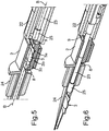
- Fig. 5 in a perspective illustration, which also shows a cross-section, the cassette 1 is shown in a state, in which the tear-off element 14 with the foils 10 and 16 is completely separated from the receiving container 2.
- the front end of the piston 23 has a damping element 25 in particular formed of silicone. It then contacts the intraocular lens 3 on the way along the axis B, if the piston 23 has penetrated the receiving container 2 via the opening 9. Therein, a haptic part 3a of the lens 3 is in particular contacted. On the opposing side of an optic part 3b, then, a further haptic part 3c is similarly formed.
- the lens 3 is then pushed out of the receiving container 2 via the front opening 8 and introduced into the channel of the injector tip 24. This is shown in the illustration according to Fig. 6 .
- a cassette 1 is provided, which has a receiving container 2.
- This cassette 1 does not include a tear-off element 14, as it is provided in Fig. 1 .
- a coextruded foil 10 is again disposed on the face 6 on the receiving container 2 and an opening 8 is sterilely and sealingly closed.
- the foil 10 is only attached in a single layer and has a defined perforation structure 26.
- an injector tip 24 of the injector device 21 includes a perforation element 27 on the side facing the cassette 1.
- the perforation structure 26 is automatically severed by the perforation element 27.
- the access to the interior of the receiving container 2 and thus to the intraocular lens 3 is thereby given.
- the intraocular lens 3 can then be pushed out of the receiving container 2 via the opened foil 10 in the region of the pierced perforation structure 26.
- a corresponding foil 16 is also attached in a single layer on the opposing face 7 of the receiving container.
- This coextruded foil 16 too has a perforation structure. Then, it can be pierced with the front end of the piston 23.
- Fig. 8 a perspective illustration of the implementation in Fig. 7 is shown, wherein moreover a cross-section is also shown. Therein, the shape and geometry of the perforation element 27 can be recognized.
- the intraocular lens 3 is not drawn.
- a damper element 28 is disposed in the interior 4 of the receiving container 2, which is for example formed of silicone. It is disposed adjacent to the foil 16 and disposed between this foil 16 and the not shown intraocular lens 3.
- this elastic damper element 28 which has the analogous function to the damper element 25 in Fig. 5 and Fig. 6 , damage to the intraocular lens 3 upon pushing out is prevented.
- the front end of the piston 23 is relatively hard and optionally also formed with a perforation edge. This to the effect that a perforation structure 29 formed in the foil 16 can be pierced.
- the damper element 28 is of particular advantageousness.
- a further embodiment not comprised of the invention of a cassette 1 on the one hand and of an injector device 21 on the other hand is shown.
- a cassette 1 is also again formed without abrasion element for removing the foils 10 and 16.
- the shape of the receiving container 2 is here different from the previous embodiments. Thereby, different injector tips 24 and/or different injector tubes 22 can optionally be combined and connected to the cassette 1.
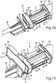
- FIG. 10 a perspective illustration of the embodiment according to Fig. 9 is shown.
- the perforation structure 26 as it is formed in the foil 10, is realized as a cross.
- the perforation structure 29 in the foil 16 is also correspondingly realized.
- passages 30, 31, 32 and 33 are formed on the body of the receiving container 2. They are formed for guiding through and snapping by locking elements 34, 35, 36 and 37.
- the cassette 1 can be disposed locking to the injector tube 22 in non-destructively detachable manner.
- integral attachment is possible and the entire injector device 21 can be delivered already completely assembled.
- the injector tip 24 is not yet attached to the cassette 1 in its final position such that the perforation structure 26 then is not yet pierced.
- a further embodiment of a cassette 1 and a further embodiment of an injector device 21 are shown.
- a front opening 8 of the receiving container 2 facing the injector tip 24 is closed by a two-layer attached foil 10.
- the tear-off element 14 is not oriented in the x-y plane, but in the y-z plane.
- the second layer 12 of the foil 10 is attached to the center plate element of the tear-off element 14. The remaining arrangement and removal of the foil 10 from the front face 6 is analogous to the explanation in Fig. 1 .
- the opening 9 facing away from the injector tip 24 is sterilely and sealingly covered with a foil 16 analogously to the configurations in Fig. 7 to Fig. 10 , which is formed without such a tear-off element. Rather, analogously to the explanations in Fig. 7 to Fig. 10 , a perforation structure 29 is formed here, which can be pierced by the piston 23.
Landscapes
- Health & Medical Sciences (AREA)
- Ophthalmology & Optometry (AREA)
- Cardiology (AREA)
- Oral & Maxillofacial Surgery (AREA)
- Transplantation (AREA)
- Engineering & Computer Science (AREA)
- Biomedical Technology (AREA)
- Heart & Thoracic Surgery (AREA)
- Vascular Medicine (AREA)
- Life Sciences & Earth Sciences (AREA)
- Animal Behavior & Ethology (AREA)
- General Health & Medical Sciences (AREA)
- Public Health (AREA)
- Veterinary Medicine (AREA)
- Prostheses (AREA)
Description
- The invention relates to a cassette for an intraocular lens, which has a receiving container for the intraocular lens. This receiving container has a front and a rear face viewed in axial direction. Moreover, the invention also relates to an injector device for an intraocular lens with such a cassette.
- Cassettes for intraocular lenses are known in manifold configuration. Thus, for example from
WO 2010/031196 A1 , such a cassette is known, which has a lid part and a bottom part. An intraocular lens is insertable into this cassette. The cassette has a front and a rear opening such that a channel is formed. A piston can be introduced into an injector device through the rear opening, which then pushes the intraocular lens out of the cassette through the front opening. - In known implementations of cassettes it is usual that they are for example manufactured and provided of plastic. Usually, a container is provided separately thereto, in which the intraocular lens is sterilely disposed. Only when a surgical procedure is imminent, this container with the intraocular lens, which is filled with liquid, is opened, the intraocular lens is removed from it and it is only then introduced into the cassette. The cassette is then attached to the injector device and the already above mentioned piston pushes the lens out of the cassette.
- Thus, first, the lens is provided and supplied in a separate transport container. The cassette is supplied separately thereto. First, then, an elaborate introduction process of the lens into the cassette has to be effected. Therein, damage to the lens can also occur and optionally the sterility can also be affected.
- Moreover, the user is also required to first go through a certain learning phase in order to be able to perform the correct introduction of the lens into the cassette on the one hand and the correct mounting of the cassette to the injector device on the other hand without error.
- From
document DE 10 2005 004 598 A1 an apparatus to implant an intraocular lens is known. - Moreover, document
WO 2004/060099 A2 discloses a packaging for storing a contact lens in sterile fluid. - Furthermore, document
US 2008/0147080 A1 shows a cassette for an intraocular lens in which openings are closed by foils. - It is the object of the present invention to provide a cassette for an intraocular lens as well as an injector device for an intraocular lens, by which the handling of an intraocular lens can be effected simply and with less effort.
- This object is solved by a cassette and an injector device having the features of the independent claims.
- A cassette according to the invention is formed for receiving an intraocular lens. The cassette includes a receiving container for the intraocular lens. The receiving container has a front and a rear face viewed in axial direction of the receiving container. The front face has an opening, which is closed by a foil attached to the receiving container as a cover, and/or the rear face has an opening, which is closed by a foil attached to the receiving container as a cover. Thus, the cassette is formed with its two openings in order that upon arrangement on the injector device a piston of the injector device can penetrate the cassette through one of the openings and push the intraocular lens then located therein out of the cassette. The cassette thus does not constitute a transport container for an intraocular lens, but a module, which can directly be attached to the injector device for further treatment of the intraocular lens located therein or is integrally formed in the injector device itself.
- In that at least one of the openings on the face of the receiving container is closed by a very thin foil, it can be allowed that the intraocular lens is already directly inserted in the cassette and the cassette is therefore multi-functionally formed. This, because it therefore also has the integral function of the transport container. Thus, the cassette according to the invention is a component constituting the transport container itself on the one hand, constituting also exactly that component on the other hand, which is or can be connected to the injector device and which then allows in the state connected to the injector device that the intraocular lens located therein can be pushed out of the cassette. By the foil, a mechanically stable closure is allowed on the one hand, which also allows the sterile storage of the intraocular lens in the cassette on the other hand.
- Preferably, a balanced saline solution or pure water is disposed in the interior of the receiving container. The intraocular lens located therein is thereby sterilely stored.
- By the attachment of a foil to at least one of the faces, this foil can also be processed simply and with low effort, in order to then be able to bring out the intraocular lens from the receiving container in the following. This, in particular when this intraocular lens is to be pushed out of this cassette by a piston of the injector device.
- Thus, the cassette according to the invention integrates a plurality of functions in a single component, which requires a plurality of separate components in conventional configurations and requires additional handling effort on the other hand.
- Thus, in particular after completion of the cassette, the intraocular lens is introduced into the receiving container and the balanced saline solution is introduced. Thereafter, at least one of the openings is closed with the foil. The thus provided cassette therefore includes a hermetically sealed receiving container, in which the intraocular lens is already sterilely stored and integrated. A so formed cassette can then furthermore already be integrated in an injector device such that already the complete injector device can be provided and then subsequently delivered and optionally supplied to a surgeon. In such a configuration, thus, the amount of work and in particular the mounting effort is minimized.
- It is particularly advantageous if a foil is a coextruded foil. For such a specific foil it is possible in a manner particularly to be emphasized that a hermetically tight seal of the opening with the foil can be ensured on the one hand. On the other hand, it is thereby achieved that a particularly sterile barrier is also generated by the foil such that undesired contaminants cannot enter the interior of the receiving container. Moreover, this coextruded foil further ensures the desired flexibility with regard to the subsequent removal or piercing when the intraocular lens is to be pushed out of the cassette.
- It is advantageous that the coextruded foil has an aluminum layer. Herein, aluminum is a material particularly to be emphasized in order to be able to ensure the sterile barrier of the foil.
- Advantageously, it is provided that the coextruded foil has propylene, in particular includes a polypropylene layer. In particular, this material component is suitable for hermetically sealing and attaching to the receiving container. Therein, the polypropylene material can be particularly sealingly connected to the material in the receiving container.
- Preferably, the coextruded foil is formed to the effect that it has a polypropylene layer, on which an aluminum layer is formed. The aluminum layer is then preferably further covered with a varnish or other coating.
- Preferably, it is provided that the foil has a thickness between 0.30 mm and 6 mm, preferably between 0.3 mm and 2 mm, preferably between 0.3 mm and 1 mm, preferably between 0.45 mm und 0.55 mm, in particular 0.5 mm. Such a thin foil is highly flexible on the one hand and can be easily and safely torn off with a suitable handling tool without it tearing apart. Similarly, it can be specifically and desirably pierced with a suitable handling tool without it undesirably being disrupted.
- On the other hand, it also ensures a sufficient thickness to be able to prevent undesired piercing or detaching. In particular, a sufficient thickness is provided in order to be able to attach the foil mechanically safely and sealingly to the receiving container and to be able to ensure the sterility for the interior of the receiving container.
- The foil is connected to a tear-off element, which is movable relatively to the receiving container for tearing off the foil from the receiving container. Thereby, a particularly simple handling means is ensured, which thus is similarly already formed and present integrally with the cassette. Here too, thus, assembly effort is omitted. On the other hand, the tear-off element is disposed and connected to the foil such that an intuitively correct movement sequence is performed and thus detaching and tearing-off of the foil is automatically effected in the preferred direction. The above mentioned advantages are thereby once again supported.
- Preferably, the tear-off element is designed as a plate-like grip part. Thereby, a user can safely grip and hold the tear-off element. Thereby, slip-off is prevented.
- Preferably, it is provided that a foil is formed in two layers on an opening. This is in particular designed to the effect that the layer closer to the receiving container is fixedly connected thereto such that the seal and sterile barrier is ensured. The second layer facing away from the receiving container is in particular designed to the effect that it is in particular not fixedly connected to the first layer in the superposition region with the first layer. Thus, a certain relative mobility to the first layer is ensured.
- Preferably, the second layer is connected to the tear-off element. Thus, especially with regard to the attachment of the foil to the tear-off element on the one hand and the receiving container, a safe function chain with regard to the removal of the foil from the receiving container can be ensured. The tear-off operation is thus allowed in particularly simple and target-aimed manner, such that tearing-off of the foil from the receiving container is ensured without tearing the foil apart.
- The foil is integrally formed, in particular formed as a strip. A bend is formed at the end of the foil facing away from the tear-off element and a second foil layer outside with respect to the opening of the receiving container is connected to the tear-off element with the free end facing away from the bend. The above mentioned advantages are therein achieved in a manner particularly to be emphasized. Because, if the tear-off element is pulled away from the cassette, thus, the location of the bend is virtually pulled further and further and a particularly suitable force introduction to the first foil layer with regard to its detachment from the receiving container can be ensured. A particularly uniform and unidirectional detachment of the first foil layer from two opposing attachment lines on the receiving container is thereby ensured.
- Preferably, a foil is thermally welded to the receiving container. Thereby, a particularly simple yet very sealing connection can be provided. Especially if the receiving container is a plastic material and the polypropylene material of the coextruded foils is heated, a particularly sealing connection between the plastic materials can be achieved.
- Preferably, it is provided that a displaceable elastic damper element (or soft cushion) is disposed in the receiving container on the opening of the receiving container constituting an input-side opening. Therein, the input-side opening constitutes that opening of the receiving container, which faces a piston of an injector device for pushing-out the intraocular lens, if the cassette is disposed in the injector device. Preferably, this damper element is positioned immediately on the inner side of the foil, which closes this input-side opening. This damper element is thus disposed between this foil, which closes the input-side opening and the intraocular lens located in the receiving container.
- The damper element is preferably formed of an elastomer, in particular silicone. By such an integrated damper element, a particular advantageousness can be achieved in a specific configuration of the cassette and thus also of an injector device such that exactly then a very hard and stiff piston can be used, by which the foil closing the input-side opening of the cassette can be pierced very specifically in desired manner. In that the damper element is further located behind, thus, a soft component is provided, which then serves as an adapter in order to contact the intraocular lens and push it out of the cassette. Thus, it can be avoided that the very hard and stiff piston directly contacts the intraocular lens and optionally would be able to damage it.
- Thus, with this damper element, a buffer for the piston optionally harder striking the receiving container is virtually formed on the one hand. On the other hand, the damper element then ensures a particularly gentle contact with the intraocular lens in the further process of pushing the intraocular lens out of the cassette. On the other hand, a particularly suitable push-out piston provided with a hard front end can be used, as already mentioned, which in turn ensures the advantageousness of the safe and desired piercing of the foil of the cassette.
- However, it is to be mentioned that such a damper element can also be disposed in the receiving container in any other implementation of the cassette. Thus, such a damper element can also be disposed on a cassette, in which one or both foils closing the openings on the face are removed with a tear-off element.
- In the configuration of the cassette, different implementations can be provided. Here, it can be provided that for example both openings are closed with each one foil. In such a configuration, it can then be provided that both foils are connected to a single tear-off element and with the movement of the tear-off element both foils are torn off the receiving container at the same time.
- In another implementation, it can also be provided that each foil is connected to an own separate tear-off element.
- Similarly, it can be provided that only one of the two foils is connected to a tear-off element and the connected foil is then removed from the receiving container by actuating the tear-off element. The second foil is then formed without such a tear-off element. It can then be designed to the effect that it can be pierced by a piston of the injector device. In particular, it can have a perforation structure for this such that piercing the foil is effected in very specific manner and at a very specific location.
- In particular it is provided that thus the input-side opening is then formed without such a tear-off element. The output-side opening is then formed with this tear-off element.
- In a further implementation it can be provided that the output-side opening of the cassette is formed without such a tear-off element. In particular, this foil then has a characterizing perforation structure. In such a configuration, it can then be provided that an injector tip of the injector device, which is formed as a separate component, has a perforation element. Upon attachment of the injector tip to the injector tube, then, the foil attached to the output side is automatically pierced at the desired location and in the desired manner by this perforation element. In such a configuration, it can be provided that the foil formed on the input-side opening is connected to a tear-off element. However, preferably, it can here be provided that the foil attached to the input-side opening is also formed without such a tear-off element and also in particular has a specific perforation structure. It can then be pierced by the mentioned piston of the injector device.
- Preferably, the cassette includes a container with viscoelastic material, which is subsequently disposed on the receiving container, in particular the container is closed in covering manner in axial direction on both sides with a foil, in particular a coextruded foil.
- Preferably, at least one foil has a defined perforation structure already mentioned above. This perforation structure can in particular be crossed lines, especially two crossed lines, especially a cross with lines are perpendicular to each other.
- Such a cross structure, which is in particular then also centrally formed on a foil, ensures a particularly safe and centered piercing of a foil, thereby also providing a maximum tear-open geometry to be able to output the lens simply and via a perforation opening as large as possible.
- Especially the cassette is a receiving container to store a hydrophilic lens in water medium (pure or salted water).
- Furthermore, the invention relates to an injector device for an intraocular lens with a cassette according to the invention or an advantageous configuration thereof. In particular, the injector device includes an injector tube, on which the cassette is disposed.
- In particularly advantageous manner, it is provided that the injector device already has the cassette in integrated manner. Thus, a highest degree of integration of components is virtually achieved, which ensure the transport of an intraocular lens to a surgeon on the one hand and the handling by a surgeon on the other hand. Thereby, assembly effort for the cassette to the injector device on the one hand, in particular for the medical personnel, and any effort for introducing the intraocular lens from a separate transport container into the cassette, in particular by the medical personnel, is no longer required.
- Preferably, the injector device has an injector tip formed with a perforation edge or a perforation element. With this perforation edge, the foil of the cassette facing the injector tip is automatically severable upon arrangement of the injector tip on an injector tube of the injector device. The above already mentioned advantages correspondingly apply here.
- Preferably, the injector device has a piston for pushing the intraocular lens out of the cassette, which also has a perforation means or a perforation element, by which upon the piston striking a foil of the cassette facing the piston, this foil is automatically severable. Here too, the already above mentioned advantages apply in analogous manner.
- Preferably, it is provided that the cassette is steam sterilized and the injector tip and the injector tube are sterilized with ethylene oxide.
- Preferably, it is provided that the injector device is provided and deliverable with a cassette integrated therewith in a closed transport container. As already above mentioned, this is particularly advantageous. Because the medical personnel then only has to open this transport container and can remove the overall injector device thereupon and begin with the further handling of the injector device without further assembly process or removal process of the intraocular lens from a separate transport container or introduction into the cassette.
- Further features of the invention are apparent from the claims, the figures and the description of figures. The features and feature combinations mentioned above in the description as well as the features and feature combinations shown in the description of figures alone and/or the features and feature combinations shown only in the figures alone are usable not only in the respectively specified combination, but also in other combinations or alone, without departing from the scope of the invention.
- Embodiments of the invention are explained in more detail below by way of schematic drawings.
- There show:
- Fig. 1
- a perspective illustration of an embodiment of a cassette according to the invention;
- Fig. 2
- a perspective illustration of an embodiment of an injector device according to the invention;
- Fig. 3
- a perspective illustration of a partial section of the injector device according to
Fig. 1 in a first handling state; - Fig. 4
- a perspective illustration of a partial section of the injector device according to
Fig. 2 in a second handling state; - Fig. 5
- a perspective illustration with a cross-section of a partial section of the injector device according to
Fig. 2 in a third handling state; - Fig. 6
- a perspective partial section with a sectional view of the injector device according to
Fig. 3 in a fourth handling state; - Fig. 7
- a perspective illustration of partial components of an injector device according to an embodiment not comprised of the invention;
- Fig. 8
- a perspective illustration with a sectional view of the implementation according to
Fig. 7 ; - Fig. 9
- a perspective illustration with a sectional view of a further embodiment of an injector device not comprised of the invention;
- Fig. 10
- a perspective illustration of the implementation in
Fig. 9 ; - Fig. 11
- a perspective illustration of a partial section of a further embodiment of an injector device according to the invention;
- In the embodiment, similar or functionally equivalent elements are provided with the same reference characters.
- In
Fig. 1 , in a perspective illustration, a first embodiment of acassette 1 is shown. Thecassette 1 includes a receivingcontainer 2 rectangular in the embodiment, in which anintraocular lens 3 is disposed. Thereto, the receivingcontainer 2 includes an internal space 4, which is filled with abalanced saline solution 5, or water medium. - The receiving
container 2 includes afront face 6 and arear face 7 viewed in direction of its longitudinal axis A. Anopening 8 is formed in thefront face 6. Similarly, anopening 9 is formed in therear face 7. Theopenings intraocular lens 3 can be correspondingly input and output. - Thus, the
cassette 1 is formed for receiving theintraocular lens 3. Moreover, it is also provided for directly attaching to an injector for introducing theintraocular lens 3 into an eye. - Preferably, it is provided that this
cassette 1 is integrally disposed on such an injector. Therein, theopenings opening 8, and thereby theintraocular lens 3 can be pushed out of the receivingcontainer 2 via theopening 8. - Moreover, the
cassette 1 includes afirst coextruded foil 10. Thiscoextruded foil 10 includes polypropylene as a first layer and an aluminum layer attached thereon. It is then in turn covered by a varnish layer or the like. Thecoextruded foil 10 extends across the entire width (y direction) of the receivingcontainer 2 with afirst layer 11. With regard to its height (z direction), thefoil 10 is formed substantially corresponding to the height of the receivingcontainer 2. Thisfirst layer 11 of thefoil 10 is directly attached to the receivingcontainer 2, in particular sealingly disposed thereon by thermally welding. Thus, thefront opening 8 is sterilely sealed by thisfoil 10 in particular with thefirst layer 11. - Therein, a sufficiently tight attachment to the plastic of the receiving
container 2 is ensured by the polypropylene layer. By the aluminum layer it is ensured that theintraocular lens 3 and the interior of the receivingcontainer 2 can be maintained sterile. - The
foil 10 strip-like in the embodiment moreover includes asecond layer 12. Thefoil 10 is integrally formed and the twolayers like foil 10 is bent at abend 13 and thereby the two-layeredness on thefront face 6 is produced. Thissecond layer 12 extends in the y direction beyond the length of thefirst layer 11 and is attached to a plate-shaped tear-offelement 14. With regard to its length (x direction), the plate-shaped tear-offelement 14 is formed with a length corresponding to the length of the receivingcontainer 2. As is apparent, the tear-offelement 14 is disposed abutting a longitudinal side of the receivingcontainer 2. - The
second layer 12 is attached to a face of a plate-like receivingpart 15 of the tear-offelement 14. Thislayer 12 also extends over the entire length of this receivingpart 15. - On the opposing side, an analogous configuration is formed. There too, a
foil 16 being a coextruded foil of polypropylene and aluminum is disposed such that theopening 9 is sealingly and sterilely closed. Here too, afirst layer 17 is directly disposed on the receivingcontainer 2 and asecond layer 19 of theintegral foil 16 is formed via abend 18. Here too, thissecond layer 19 is then attached to a receivingelement 20 of the tear-offelement 14 on the outside. - The foils 10 and 16 have a thickness between 0.45 mm and 0.55 mm, in particular 0.5 mm, with respect to a layer.
- For removing the
foils element 14 is gripped and peeled off in the direction of the arrow P1 and thus in particular in the x-y plane. Thereby, thebend first layers container 2 are detached from the receivingcontainer 2. - In particular it is provided that the thus shown
cassette 1 is already provided as a prefabricated unit and corresponding module and can be correspondingly supplied and transported. Then, it can be provided that it is plugged or locked to a present injector device or attached thereto in correspondingly other manner in situ. - In thus particularly advantageous manner, it is no longer required that the
intraocular lens 3 is provided and delivered in a separate transport container and a cassette is provided and delivered as a separate component and then the intraocular lens has to be introduced into the cassette only in situ in elaborate and error-prone manner as well as optionally unhygienic manner. Exactly this all can therefore be prevented if an implementation according toFig. 1 is formed. - In
Fig. 2 , in a perspective illustration, an embodiment of aninjector device 21 according to the invention is shown. Thisinjector device 21 is constructed syringe-like and includes aninjector tube 22. Apiston 23 is guided in it, which can be displaced in the direction of the longitudinal axis B. Moreover, theinjector tube 22 is formed for receiving acassette 1 as it has for example been shown and explained inFig. 1 . The front-side end of theinjector device 21 constitutes aninjector tip 24. - In the shown embodiment, it is in particular provided that the
cassette 1 is integrated in theinjector tube 22. Thus, it can be provided that theentire injector device 21 is already completely finished and delivered such that it is also no longer required with medical personnel in situ that thecassette 1 still has to be mounted to theinjector tube 22. - In particularly advantageous manner, the
injector device 21 is sterilized with ethylene oxide and thecassette 1 is steam sterilized. - As an alternative the complete device (injector and cassette) is gamma sterilized in one step, after complete packaging.
- In preferred manner, the
entire injector device 21 with the already disposedcassette 1 is stored in a transport container and then already finished delivered in situ for example to a surgeon with this transport container. The user then only has to open thetransport container 1 and remove theinjector device 21 shown inFig. 2 from it. - By actuating the
piston 23 and thus by pushing thepiston 23 in the direction of the axis B, the piston tip not shown inFig. 2 enters the receivingcontainer 2. Then, theintraocular lens 3 located therein is pushed out of the receivingcontainer 2 and thus also from thefront opening 8 along the axis B of theinjector device 21 and pushed into theinjector tip 24. There, it then exits at the front cannula end in rolled or folded manner and can be introduced into the eye. - In
Fig. 3 , in perspective illustration, an enlarged section of theinjector device 21 in the region of thecassette 1 is shown. Here, a state is shown, in which the cassette is minimally opened and thus the tear-offelement 14 is only slightly pulled in the direction of the arrow P1. Theopenings - In
Fig. 4 , a further perspective illustration of the partial section according toFig. 3 is shown, wherein here the tear-offelement 14 has already been further pulled in the direction of the arrow P1. Therein, it can be recognized that thefirst layers foils faces container 2. In this connection, theopening 9 is already perceivable. - In
Fig. 5 , then, in a perspective illustration, which also shows a cross-section, thecassette 1 is shown in a state, in which the tear-offelement 14 with thefoils container 2. - Moreover, it can be recognized that the front end of the
piston 23 has a dampingelement 25 in particular formed of silicone. It then contacts theintraocular lens 3 on the way along the axis B, if thepiston 23 has penetrated the receivingcontainer 2 via theopening 9. Therein, ahaptic part 3a of thelens 3 is in particular contacted. On the opposing side of anoptic part 3b, then, a further haptic part 3c is similarly formed. - As already mentioned, the
lens 3 is then pushed out of the receivingcontainer 2 via thefront opening 8 and introduced into the channel of theinjector tip 24. This is shown in the illustration according toFig. 6 . - In
Fig. 7 , in a perspective illustration, a further embodiment not comprised of the invention of partial components of aninjector device 24 is shown. In this configuration, acassette 1 is provided, which has a receivingcontainer 2. Thiscassette 1 does not include a tear-offelement 14, as it is provided inFig. 1 . Rather, here it is provided that acoextruded foil 10 is again disposed on theface 6 on the receivingcontainer 2 and anopening 8 is sterilely and sealingly closed. In this embodiment, it is provided that thefoil 10 is only attached in a single layer and has a definedperforation structure 26. In this configuration aninjector tip 24 of theinjector device 21 includes aperforation element 27 on the side facing thecassette 1. It can have a very specifically defined perforation edge. Upon assembling theinjector tip 24 to thecassette 1, thus, theperforation structure 26 is automatically severed by theperforation element 27. The access to the interior of the receivingcontainer 2 and thus to theintraocular lens 3 is thereby given. Theintraocular lens 3 can then be pushed out of the receivingcontainer 2 via the openedfoil 10 in the region of thepierced perforation structure 26. - Correspondingly, it can be provided that a
corresponding foil 16 is also attached in a single layer on the opposingface 7 of the receiving container. Thiscoextruded foil 16 too has a perforation structure. Then, it can be pierced with the front end of thepiston 23. - In
Fig. 8 , a perspective illustration of the implementation inFig. 7 is shown, wherein moreover a cross-section is also shown. Therein, the shape and geometry of theperforation element 27 can be recognized. For the sake of clarity, inFig. 8 , theintraocular lens 3 is not drawn. At this point, it is to be mentioned that adamper element 28 is disposed in the interior 4 of the receivingcontainer 2, which is for example formed of silicone. It is disposed adjacent to thefoil 16 and disposed between thisfoil 16 and the not shownintraocular lens 3. By thiselastic damper element 28, which has the analogous function to thedamper element 25 inFig. 5 and Fig. 6 , damage to theintraocular lens 3 upon pushing out is prevented. Because in a configuration as it is shown inFig. 7 and Fig. 8 , it is advantageous that the front end of thepiston 23 is relatively hard and optionally also formed with a perforation edge. This to the effect that aperforation structure 29 formed in thefoil 16 can be pierced. However, since such a hard andinflexible piston 23 could then damage theintraocular lens 3, thedamper element 28 is of particular advantageousness. By the integral arrangement of thedamper element 28 in the receivingcontainer 2, here too, a functional integration is ensured and the attachment of such adamper element 28 to thepiston 23, if thisdamper element 28 would not be present integrated in the receivingcontainer 2, can no longer be forgotten. - In
Fig. 9 , a further embodiment not comprised of the invention of acassette 1 on the one hand and of aninjector device 21 on the other hand is shown. - In this configuration, a
cassette 1 is also again formed without abrasion element for removing thefoils container 2 is here different from the previous embodiments. Thereby,different injector tips 24 and/ordifferent injector tubes 22 can optionally be combined and connected to thecassette 1. - In
Fig. 10 , a perspective illustration of the embodiment according toFig. 9 is shown. Theperforation structure 26 as it is formed in thefoil 10, is realized as a cross. Theperforation structure 29 in thefoil 16 is also correspondingly realized. As it can be appreciated,passages container 2. They are formed for guiding through and snapping by lockingelements cassette 1 can be disposed locking to theinjector tube 22 in non-destructively detachable manner. Thereby, integral attachment is possible and theentire injector device 21 can be delivered already completely assembled. However, in particular, theinjector tip 24 is not yet attached to thecassette 1 in its final position such that theperforation structure 26 then is not yet pierced. - In
Fig. 11 , in a perspective illustration, a further embodiment of acassette 1 and a further embodiment of aninjector device 21 are shown. In this configuration, unlike the implementations inFig. 1 andFig. 7 toFig. 10 , it is provided that afront opening 8 of the receivingcontainer 2 facing theinjector tip 24 is closed by a two-layer attachedfoil 10. In this configuration, the tear-offelement 14 is not oriented in the x-y plane, but in the y-z plane. Therein, thesecond layer 12 of thefoil 10 is attached to the center plate element of the tear-offelement 14. The remaining arrangement and removal of thefoil 10 from thefront face 6 is analogous to the explanation inFig. 1 . - In contrast, the
opening 9 facing away from theinjector tip 24 is sterilely and sealingly covered with afoil 16 analogously to the configurations inFig. 7 to Fig. 10 , which is formed without such a tear-off element. Rather, analogously to the explanations inFig. 7 to Fig. 10 , aperforation structure 29 is formed here, which can be pierced by thepiston 23.
Claims (15)
- Cassette (1) for an intraocular lens (3), which has a receiving container (2) for the intraocular lens (3), which has a front (6) and a rear face (7) in the axial direction (A) of the receiving container (2), wherein
the front face (6) has an opening (8), which is closed by a foil (10) attached to the receiving container (2) as a cover, and/or the rear face (7) has an opening (9), which is closed by a foil (16) attached to the receiving container (2) as a cover,
characterized in that
said foil (10, 16) is connected to a tear-off element (14), which is movable relatively to the receiving container (2) for tearing off the foil (10, 16) from the receiving container (2), and
the foil (10, 16) is integrally formed and has a bend (13, 18) at the end facing away from the tear-off element (14), and a second foil layer (12, 19) outside with respect to the opening (8, 9) of the receiving container (2) is connected to the tear-off element (14) at the free end facing away from the bend (13, 18). - Cassette (1) according to claim 1,
characterized in that
said foil is a coextruded foil (10, 16). - Cassette (1) according to claim 2,
characterized in that
said coextruded foil (10, 16) comprising aluminum. - Cassette (1) according to claim 2 or 3,
characterized in that
said coextruded foil (10, 16) comprising polypropylene. - Cassette (1) according to anyone of the preceding claims,
characterized in that
the foil (10, 16) has a thickness between 0.3 mm and 6 mm, in particular 0,3 mm and 1 mm, in particular 0.5 mm. - Cassette (1) according to anyone of the preceding claims,
characterized in that
said foil (10, 16) is formed in two layers on an opening (8, 9). - Cassette (1) according to anyone of the preceding claims,
characterized in that
said foil (10, 16) is thermally welded to the receiving container (2). - Cassette (1) according to anyone of the preceding claims,
characterized in that
a displaceable elastic damper element (28) is disposed in the receiving container (2) on the opening (9) constituting an input-side opening for a piston (23) on an injector device (21). - Cassette (1) according to anyone of the preceding claims,
characterized in that
said foil (10, 16) has a defined perforation structure (26, 29). - Cassette (1) according to claim 9,
characterized in that
the perforation structure (26, 29) includes at least two crossed lines. - Injector device (21) for an intraocular lens (3), including a cassette (1) according to anyone of the preceding claims, in particular a cassette (1) fixedly disposed of an injector tube (22).
- Injector device (21) according to claim 11,
characterized in that
the injector device (21) has an injector tip (24) formed with a perforation edge (27), with which the foil (10, 41) of the cassette (1) facing the injector tip (24) is automatically severable upon arrangement of the injector tip (24) on an injector tube (22) of the injector device (21). - Injector device (21) according to claim 11 or 12,
characterized in that
injector device (21) has a piston (23) for pushing the intraocular lens (3) out of the cassette (1), which has a perforation means, by which upon the piston (23) striking a foil (16) of the cassette (1) facing the piston (23), this foil (16) is automatically severable. - Injector device (21) according to any one of claims 11 to 13,
characterized in that
the cassette (1) is steam sterilized and the injector tip (24) and the injector tube (22) are sterilized with ethylene oxide. - Injector device (21) according to any one of claims 11 to 14,
characterized in that
it is disposed in a closed transport container together with the cassette (1) disposed thereon.
Applications Claiming Priority (2)
| Application Number | Priority Date | Filing Date | Title |
|---|---|---|---|
| GB1112580.4A GB2493017B (en) | 2011-07-19 | 2011-07-19 | Cassette for an intraocular lens and injector device for an intraocular lens |
| PCT/EP2012/064001 WO2013011024A1 (en) | 2011-07-19 | 2012-07-17 | Cassette for an intraocular lens and injector device for an intraocular lens |
Publications (2)
| Publication Number | Publication Date |
|---|---|
| EP2734151A1 EP2734151A1 (en) | 2014-05-28 |
| EP2734151B1 true EP2734151B1 (en) | 2018-01-31 |
Family
ID=44586976
Family Applications (1)
| Application Number | Title | Priority Date | Filing Date |
|---|---|---|---|
| EP12740332.7A Active EP2734151B1 (en) | 2011-07-19 | 2012-07-17 | Cassette for an intraocular lens and injector device for an intraocular lens |
Country Status (7)
| Country | Link |
|---|---|
| EP (1) | EP2734151B1 (en) |
| JP (1) | JP6000348B2 (en) |
| CN (1) | CN103813763B (en) |
| ES (1) | ES2661098T3 (en) |
| GB (1) | GB2493017B (en) |
| HK (1) | HK1195482A1 (en) |
| WO (1) | WO2013011024A1 (en) |
Families Citing this family (3)
| Publication number | Priority date | Publication date | Assignee | Title |
|---|---|---|---|---|
| DE102013105184B4 (en) * | 2013-05-21 | 2020-02-20 | Carl Zeiss Meditec Ag | Injector device for inserting an intraocular lens into an eye and method for folding an intraocular lens in an injector device |
| DE102019128370B3 (en) * | 2019-10-21 | 2020-12-03 | Carl Zeiss Meditec Ag | Injector for inserting an intraocular lens |
| DE102019128372B3 (en) * | 2019-10-21 | 2020-12-17 | Carl Zeiss Meditec Ag | Injector assembly for inserting an intraocular lens |
Family Cites Families (16)
| Publication number | Priority date | Publication date | Assignee | Title |
|---|---|---|---|---|
| TW295570B (en) * | 1994-05-04 | 1997-01-11 | Ciba Geigy Ag | |
| ES2207652T3 (en) * | 1994-08-05 | 2004-06-01 | BAUSCH & LOMB INCORPORATED | DEVICE FOR THE INSERTION OF A FLEXIBLE INTRAOCULAR LENS. |
| US6228094B1 (en) * | 1995-11-01 | 2001-05-08 | Micro Medical Devices, Inc. | Lens storage and folding apparatus |
| FR2833154B1 (en) * | 2001-12-12 | 2004-11-19 | Ioltechnologie Production | CASSETTE AND FLEXIBLE INTRAOCULAR LENS INJECTOR AND METHOD FOR INJECTING SUCH LENSES |
| EP2283876A1 (en) * | 2002-12-23 | 2011-02-16 | Johnson and Johnson Vision Care, Inc. | Contact lens packages containing additives |
| US7422604B2 (en) * | 2003-08-28 | 2008-09-09 | Bausch & Lomb Incorporated | Preloaded IOL injector |
| FR2869794B1 (en) * | 2004-05-06 | 2007-04-06 | Contactologie Appliquee Lca Sa | PACKAGING DEVICE FOR INTRAOCULAR LENS INJECTOR. |
| US20060142781A1 (en) * | 2004-12-29 | 2006-06-29 | Joel Pynson | Preloaded IOL injector and method |
| DE102005004598B4 (en) * | 2005-02-01 | 2011-07-21 | *Acri.Tec GmbH, 16761 | Device for implanting an intraocular lens |
| DE102005042849A1 (en) * | 2005-09-09 | 2007-03-22 | Kammann, Jochen, Prof. Dr. | Implantation tool for intraocular lenses |
| US7879090B2 (en) * | 2006-12-13 | 2011-02-01 | Bausch & Lomb Incorporated | Intraocular lens injector apparatus and methods of use |
| US20080147080A1 (en) * | 2006-12-13 | 2008-06-19 | Joel Pynson | Injector apparatus for use with intraocular lenses and methods of use |
| KR100893138B1 (en) * | 2008-09-19 | 2009-04-16 | 주식회사 알이티 | Injector for disposable intraocular lens |
| CH699588A1 (en) | 2008-09-22 | 2010-03-31 | Medicel Ag | Cartridge for an intraocular lens injector system and for it. |
| MX2011008381A (en) * | 2009-02-11 | 2011-09-06 | Alcon Res Ltd | Automated intraocular lens injector device. |
| CN102151194B (en) * | 2011-01-31 | 2013-08-14 | 爱博诺德(北京)医疗科技有限公司 | Intraocular lens preassembled injector capable of being preassembled with viscoelastic agent and viscoelastic agent loading method |
-
2011
- 2011-07-19 GB GB1112580.4A patent/GB2493017B/en active Active
-
2012
- 2012-07-17 WO PCT/EP2012/064001 patent/WO2013011024A1/en active Application Filing
- 2012-07-17 EP EP12740332.7A patent/EP2734151B1/en active Active
- 2012-07-17 ES ES12740332.7T patent/ES2661098T3/en active Active
- 2012-07-17 CN CN201280045536.4A patent/CN103813763B/en active Active
- 2012-07-17 JP JP2014520641A patent/JP6000348B2/en active Active
-
2014
- 2014-09-03 HK HK14108940.8A patent/HK1195482A1/en unknown
Also Published As
| Publication number | Publication date |
|---|---|
| JP6000348B2 (en) | 2016-09-28 |
| HK1195482A1 (en) | 2014-11-14 |
| ES2661098T3 (en) | 2018-03-27 |
| CN103813763A (en) | 2014-05-21 |
| GB2493017A (en) | 2013-01-23 |
| CN103813763B (en) | 2015-12-02 |
| JP2014529313A (en) | 2014-11-06 |
| GB201112580D0 (en) | 2011-08-31 |
| EP2734151A1 (en) | 2014-05-28 |
| WO2013011024A1 (en) | 2013-01-24 |
| GB2493017B (en) | 2016-08-03 |
Similar Documents
| Publication | Publication Date | Title |
|---|---|---|
| US11266784B2 (en) | Disinfecting cap for medical connectors | |
| EP2389972B1 (en) | A catheter assembly comprising a receptacle accomodating a catheter and a wetting fluid pouch | |
| US11160962B2 (en) | Antiseptic delivery device and method of use | |
| JP4875157B2 (en) | Acupuncture packaging containers | |
| JP4801010B2 (en) | Package | |
| US8302773B1 (en) | Multi-compartment package assembly for medical implements | |
| EP2734151B1 (en) | Cassette for an intraocular lens and injector device for an intraocular lens | |
| EP2712579B1 (en) | Package for a surgical repair kit | |
| EP2810668B1 (en) | Blood-flow-path switching device and blood-bag system | |
| AU2022287588A1 (en) | Sterilized packaging system for catheter | |
| JP2001025473A (en) | Catheter-storing sleeve | |
| JP2007503271A (en) | Needle guide | |
| KR101909244B1 (en) | Pre-filled the tube holder for medical treatment | |
| CN108367113B (en) | Method for sterile assembly of a multi-component medical device and kit therefor | |
| JP4558472B2 (en) | Medical instrument storage structure | |
| JP7468366B2 (en) | Sleeve sheet for protective cover of ultrasonic diagnostic equipment | |
| JP7450472B2 (en) | Double packaging for items intended to remain sterile | |
| JP2012183239A (en) | Protective sheath | |
| US20210386498A1 (en) | No touch sterile medical device packaging | |
| JP2012200439A (en) | Package | |
| JP2006168767A (en) | Blister pack and medical appliance storing structure | |
| JPH0761483A (en) | Bag |
Legal Events
| Date | Code | Title | Description |
|---|---|---|---|
| PUAI | Public reference made under article 153(3) epc to a published international application that has entered the european phase |
Free format text: ORIGINAL CODE: 0009012 |
|
| 17P | Request for examination filed |
Effective date: 20140219 |
|
| AK | Designated contracting states |
Kind code of ref document: A1 Designated state(s): AL AT BE BG CH CY CZ DE DK EE ES FI FR GB GR HR HU IE IS IT LI LT LU LV MC MK MT NL NO PL PT RO RS SE SI SK SM TR |
|
| RIN1 | Information on inventor provided before grant (corrected) |
Inventor name: PANKIN, DMITRY Inventor name: RATHERT, BRIAN Inventor name: RAQUIN, VINCENT |
|
| DAX | Request for extension of the european patent (deleted) | ||
| GRAP | Despatch of communication of intention to grant a patent |
Free format text: ORIGINAL CODE: EPIDOSNIGR1 |
|
| INTG | Intention to grant announced |
Effective date: 20170830 |
|
| RIN1 | Information on inventor provided before grant (corrected) |
Inventor name: RATHERT, BRIAN Inventor name: RAQUIN, VINCENT Inventor name: PANKIN, DMITRY |
|
| GRAS | Grant fee paid |
Free format text: ORIGINAL CODE: EPIDOSNIGR3 |
|
| GRAA | (expected) grant |
Free format text: ORIGINAL CODE: 0009210 |
|
| AK | Designated contracting states |
Kind code of ref document: B1 Designated state(s): AL AT BE BG CH CY CZ DE DK EE ES FI FR GB GR HR HU IE IS IT LI LT LU LV MC MK MT NL NO PL PT RO RS SE SI SK SM TR |
|
| REG | Reference to a national code |
Ref country code: GB Ref legal event code: FG4D Ref country code: CH Ref legal event code: EP |
|
| REG | Reference to a national code |
Ref country code: AT Ref legal event code: REF Ref document number: 966660 Country of ref document: AT Kind code of ref document: T Effective date: 20180215 |
|
| REG | Reference to a national code |
Ref country code: IE Ref legal event code: FG4D |
|
| REG | Reference to a national code |
Ref country code: DE Ref legal event code: R096 Ref document number: 602012042540 Country of ref document: DE |
|
| REG | Reference to a national code |
Ref country code: ES Ref legal event code: FG2A Ref document number: 2661098 Country of ref document: ES Kind code of ref document: T3 Effective date: 20180327 |
|
| REG | Reference to a national code |
Ref country code: NL Ref legal event code: MP Effective date: 20180131 |
|
| REG | Reference to a national code |
Ref country code: LT Ref legal event code: MG4D |
|
| REG | Reference to a national code |
Ref country code: AT Ref legal event code: MK05 Ref document number: 966660 Country of ref document: AT Kind code of ref document: T Effective date: 20180131 |
|
| REG | Reference to a national code |
Ref country code: FR Ref legal event code: PLFP Year of fee payment: 7 |
|
| PG25 | Lapsed in a contracting state [announced via postgrant information from national office to epo] |
Ref country code: LT Free format text: LAPSE BECAUSE OF FAILURE TO SUBMIT A TRANSLATION OF THE DESCRIPTION OR TO PAY THE FEE WITHIN THE PRESCRIBED TIME-LIMIT Effective date: 20180131 Ref country code: HR Free format text: LAPSE BECAUSE OF FAILURE TO SUBMIT A TRANSLATION OF THE DESCRIPTION OR TO PAY THE FEE WITHIN THE PRESCRIBED TIME-LIMIT Effective date: 20180131 Ref country code: NL Free format text: LAPSE BECAUSE OF FAILURE TO SUBMIT A TRANSLATION OF THE DESCRIPTION OR TO PAY THE FEE WITHIN THE PRESCRIBED TIME-LIMIT Effective date: 20180131 Ref country code: NO Free format text: LAPSE BECAUSE OF FAILURE TO SUBMIT A TRANSLATION OF THE DESCRIPTION OR TO PAY THE FEE WITHIN THE PRESCRIBED TIME-LIMIT Effective date: 20180430 Ref country code: FI Free format text: LAPSE BECAUSE OF FAILURE TO SUBMIT A TRANSLATION OF THE DESCRIPTION OR TO PAY THE FEE WITHIN THE PRESCRIBED TIME-LIMIT Effective date: 20180131 |
|
| PG25 | Lapsed in a contracting state [announced via postgrant information from national office to epo] |
Ref country code: RS Free format text: LAPSE BECAUSE OF FAILURE TO SUBMIT A TRANSLATION OF THE DESCRIPTION OR TO PAY THE FEE WITHIN THE PRESCRIBED TIME-LIMIT Effective date: 20180131 Ref country code: PL Free format text: LAPSE BECAUSE OF FAILURE TO SUBMIT A TRANSLATION OF THE DESCRIPTION OR TO PAY THE FEE WITHIN THE PRESCRIBED TIME-LIMIT Effective date: 20180131 Ref country code: AT Free format text: LAPSE BECAUSE OF FAILURE TO SUBMIT A TRANSLATION OF THE DESCRIPTION OR TO PAY THE FEE WITHIN THE PRESCRIBED TIME-LIMIT Effective date: 20180131 Ref country code: GR Free format text: LAPSE BECAUSE OF FAILURE TO SUBMIT A TRANSLATION OF THE DESCRIPTION OR TO PAY THE FEE WITHIN THE PRESCRIBED TIME-LIMIT Effective date: 20180501 Ref country code: SE Free format text: LAPSE BECAUSE OF FAILURE TO SUBMIT A TRANSLATION OF THE DESCRIPTION OR TO PAY THE FEE WITHIN THE PRESCRIBED TIME-LIMIT Effective date: 20180131 Ref country code: LV Free format text: LAPSE BECAUSE OF FAILURE TO SUBMIT A TRANSLATION OF THE DESCRIPTION OR TO PAY THE FEE WITHIN THE PRESCRIBED TIME-LIMIT Effective date: 20180131 Ref country code: BG Free format text: LAPSE BECAUSE OF FAILURE TO SUBMIT A TRANSLATION OF THE DESCRIPTION OR TO PAY THE FEE WITHIN THE PRESCRIBED TIME-LIMIT Effective date: 20180430 Ref country code: IS Free format text: LAPSE BECAUSE OF FAILURE TO SUBMIT A TRANSLATION OF THE DESCRIPTION OR TO PAY THE FEE WITHIN THE PRESCRIBED TIME-LIMIT Effective date: 20180531 |
|
| PG25 | Lapsed in a contracting state [announced via postgrant information from national office to epo] |
Ref country code: AL Free format text: LAPSE BECAUSE OF FAILURE TO SUBMIT A TRANSLATION OF THE DESCRIPTION OR TO PAY THE FEE WITHIN THE PRESCRIBED TIME-LIMIT Effective date: 20180131 Ref country code: IT Free format text: LAPSE BECAUSE OF FAILURE TO SUBMIT A TRANSLATION OF THE DESCRIPTION OR TO PAY THE FEE WITHIN THE PRESCRIBED TIME-LIMIT Effective date: 20180131 Ref country code: EE Free format text: LAPSE BECAUSE OF FAILURE TO SUBMIT A TRANSLATION OF THE DESCRIPTION OR TO PAY THE FEE WITHIN THE PRESCRIBED TIME-LIMIT Effective date: 20180131 Ref country code: RO Free format text: LAPSE BECAUSE OF FAILURE TO SUBMIT A TRANSLATION OF THE DESCRIPTION OR TO PAY THE FEE WITHIN THE PRESCRIBED TIME-LIMIT Effective date: 20180131 |
|
| REG | Reference to a national code |
Ref country code: DE Ref legal event code: R097 Ref document number: 602012042540 Country of ref document: DE |
|
| PG25 | Lapsed in a contracting state [announced via postgrant information from national office to epo] |
Ref country code: SK Free format text: LAPSE BECAUSE OF FAILURE TO SUBMIT A TRANSLATION OF THE DESCRIPTION OR TO PAY THE FEE WITHIN THE PRESCRIBED TIME-LIMIT Effective date: 20180131 Ref country code: SM Free format text: LAPSE BECAUSE OF FAILURE TO SUBMIT A TRANSLATION OF THE DESCRIPTION OR TO PAY THE FEE WITHIN THE PRESCRIBED TIME-LIMIT Effective date: 20180131 Ref country code: CZ Free format text: LAPSE BECAUSE OF FAILURE TO SUBMIT A TRANSLATION OF THE DESCRIPTION OR TO PAY THE FEE WITHIN THE PRESCRIBED TIME-LIMIT Effective date: 20180131 Ref country code: DK Free format text: LAPSE BECAUSE OF FAILURE TO SUBMIT A TRANSLATION OF THE DESCRIPTION OR TO PAY THE FEE WITHIN THE PRESCRIBED TIME-LIMIT Effective date: 20180131 |
|
| PLBE | No opposition filed within time limit |
Free format text: ORIGINAL CODE: 0009261 |
|
| STAA | Information on the status of an ep patent application or granted ep patent |
Free format text: STATUS: NO OPPOSITION FILED WITHIN TIME LIMIT |
|
| 26N | No opposition filed |
Effective date: 20181102 |
|
| PG25 | Lapsed in a contracting state [announced via postgrant information from national office to epo] |
Ref country code: SI Free format text: LAPSE BECAUSE OF FAILURE TO SUBMIT A TRANSLATION OF THE DESCRIPTION OR TO PAY THE FEE WITHIN THE PRESCRIBED TIME-LIMIT Effective date: 20180131 |
|
| REG | Reference to a national code |
Ref country code: CH Ref legal event code: PL |
|
| GBPC | Gb: european patent ceased through non-payment of renewal fee |
Effective date: 20180717 |
|
| PG25 | Lapsed in a contracting state [announced via postgrant information from national office to epo] |
Ref country code: MC Free format text: LAPSE BECAUSE OF FAILURE TO SUBMIT A TRANSLATION OF THE DESCRIPTION OR TO PAY THE FEE WITHIN THE PRESCRIBED TIME-LIMIT Effective date: 20180131 Ref country code: LU Free format text: LAPSE BECAUSE OF NON-PAYMENT OF DUE FEES Effective date: 20180717 |
|
| REG | Reference to a national code |
Ref country code: BE Ref legal event code: MM Effective date: 20180731 |
|
| REG | Reference to a national code |
Ref country code: IE Ref legal event code: MM4A |
|
| PG25 | Lapsed in a contracting state [announced via postgrant information from national office to epo] |
Ref country code: GB Free format text: LAPSE BECAUSE OF NON-PAYMENT OF DUE FEES Effective date: 20180717 Ref country code: CH Free format text: LAPSE BECAUSE OF NON-PAYMENT OF DUE FEES Effective date: 20180731 Ref country code: IE Free format text: LAPSE BECAUSE OF NON-PAYMENT OF DUE FEES Effective date: 20180717 Ref country code: LI Free format text: LAPSE BECAUSE OF NON-PAYMENT OF DUE FEES Effective date: 20180731 |
|
| PG25 | Lapsed in a contracting state [announced via postgrant information from national office to epo] |
Ref country code: BE Free format text: LAPSE BECAUSE OF NON-PAYMENT OF DUE FEES Effective date: 20180731 |
|
| PG25 | Lapsed in a contracting state [announced via postgrant information from national office to epo] |
Ref country code: MT Free format text: LAPSE BECAUSE OF NON-PAYMENT OF DUE FEES Effective date: 20180717 |
|
| PG25 | Lapsed in a contracting state [announced via postgrant information from national office to epo] |
Ref country code: TR Free format text: LAPSE BECAUSE OF FAILURE TO SUBMIT A TRANSLATION OF THE DESCRIPTION OR TO PAY THE FEE WITHIN THE PRESCRIBED TIME-LIMIT Effective date: 20180131 |
|
| PG25 | Lapsed in a contracting state [announced via postgrant information from national office to epo] |
Ref country code: HU Free format text: LAPSE BECAUSE OF FAILURE TO SUBMIT A TRANSLATION OF THE DESCRIPTION OR TO PAY THE FEE WITHIN THE PRESCRIBED TIME-LIMIT; INVALID AB INITIO Effective date: 20120717 Ref country code: PT Free format text: LAPSE BECAUSE OF FAILURE TO SUBMIT A TRANSLATION OF THE DESCRIPTION OR TO PAY THE FEE WITHIN THE PRESCRIBED TIME-LIMIT Effective date: 20180131 |
|
| PG25 | Lapsed in a contracting state [announced via postgrant information from national office to epo] |
Ref country code: CY Free format text: LAPSE BECAUSE OF FAILURE TO SUBMIT A TRANSLATION OF THE DESCRIPTION OR TO PAY THE FEE WITHIN THE PRESCRIBED TIME-LIMIT Effective date: 20180131 Ref country code: MK Free format text: LAPSE BECAUSE OF NON-PAYMENT OF DUE FEES Effective date: 20180131 |
|
| P01 | Opt-out of the competence of the unified patent court (upc) registered |
Effective date: 20230530 |
|
| PGFP | Annual fee paid to national office [announced via postgrant information from national office to epo] |
Ref country code: ES Payment date: 20230926 Year of fee payment: 12 |
|
| PGFP | Annual fee paid to national office [announced via postgrant information from national office to epo] |
Ref country code: FR Payment date: 20230725 Year of fee payment: 12 Ref country code: DE Payment date: 20230719 Year of fee payment: 12 |