EP2734017A1 - Cyclotron - Google Patents
Cyclotron Download PDFInfo
- Publication number
- EP2734017A1 EP2734017A1 EP13004888.7A EP13004888A EP2734017A1 EP 2734017 A1 EP2734017 A1 EP 2734017A1 EP 13004888 A EP13004888 A EP 13004888A EP 2734017 A1 EP2734017 A1 EP 2734017A1
- Authority
- EP
- European Patent Office
- Prior art keywords
- buncher
- cyclotron
- inflector
- yoke
- ion beam
- Prior art date
- Legal status (The legal status is an assumption and is not a legal conclusion. Google has not performed a legal analysis and makes no representation as to the accuracy of the status listed.)
- Granted
Links
- 238000010884 ion-beam technique Methods 0.000 description 36
- 150000002500 ions Chemical class 0.000 description 19
- 230000000694 effects Effects 0.000 description 14
- 230000005684 electric field Effects 0.000 description 6
- 230000001133 acceleration Effects 0.000 description 2
- 230000000737 periodic effect Effects 0.000 description 2
- ZOXJGFHDIHLPTG-UHFFFAOYSA-N Boron Chemical compound [B] ZOXJGFHDIHLPTG-UHFFFAOYSA-N 0.000 description 1
- RYGMFSIKBFXOCR-UHFFFAOYSA-N Copper Chemical compound [Cu] RYGMFSIKBFXOCR-UHFFFAOYSA-N 0.000 description 1
- 229910052796 boron Inorganic materials 0.000 description 1
- 239000004020 conductor Substances 0.000 description 1
- 229910052802 copper Inorganic materials 0.000 description 1
- 239000010949 copper Substances 0.000 description 1
- 238000009472 formulation Methods 0.000 description 1
- 239000000203 mixture Substances 0.000 description 1
- 238000002600 positron emission tomography Methods 0.000 description 1
- 238000002560 therapeutic procedure Methods 0.000 description 1
Images

Classifications
-
- H—ELECTRICITY
- H05—ELECTRIC TECHNIQUES NOT OTHERWISE PROVIDED FOR
- H05H—PLASMA TECHNIQUE; PRODUCTION OF ACCELERATED ELECTRICALLY-CHARGED PARTICLES OR OF NEUTRONS; PRODUCTION OR ACCELERATION OF NEUTRAL MOLECULAR OR ATOMIC BEAMS
- H05H7/00—Details of devices of the types covered by groups H05H9/00, H05H11/00, H05H13/00
- H05H7/02—Circuits or systems for supplying or feeding radio-frequency energy
-
- H—ELECTRICITY
- H05—ELECTRIC TECHNIQUES NOT OTHERWISE PROVIDED FOR
- H05H—PLASMA TECHNIQUE; PRODUCTION OF ACCELERATED ELECTRICALLY-CHARGED PARTICLES OR OF NEUTRONS; PRODUCTION OR ACCELERATION OF NEUTRAL MOLECULAR OR ATOMIC BEAMS
- H05H13/00—Magnetic resonance accelerators; Cyclotrons
- H05H13/005—Cyclotrons
-
- H—ELECTRICITY
- H05—ELECTRIC TECHNIQUES NOT OTHERWISE PROVIDED FOR
- H05H—PLASMA TECHNIQUE; PRODUCTION OF ACCELERATED ELECTRICALLY-CHARGED PARTICLES OR OF NEUTRONS; PRODUCTION OR ACCELERATION OF NEUTRAL MOLECULAR OR ATOMIC BEAMS
- H05H13/00—Magnetic resonance accelerators; Cyclotrons
-
- H—ELECTRICITY
- H05—ELECTRIC TECHNIQUES NOT OTHERWISE PROVIDED FOR
- H05H—PLASMA TECHNIQUE; PRODUCTION OF ACCELERATED ELECTRICALLY-CHARGED PARTICLES OR OF NEUTRONS; PRODUCTION OR ACCELERATION OF NEUTRAL MOLECULAR OR ATOMIC BEAMS
- H05H7/00—Details of devices of the types covered by groups H05H9/00, H05H11/00, H05H13/00
- H05H7/12—Arrangements for varying final energy of beam
- H05H2007/122—Arrangements for varying final energy of beam by electromagnetic means, e.g. RF cavities
Definitions
- the present invention relates to a cyclotron having a buncher.
- Japanese Unexamined Patent Application Publication No. 2004-31115 discloses a cyclotron having an external ion source, in which a buncher is provided before a stage to make the ion beam emitted from the external ion source incident on the cyclotron center.
- Such a buncher is used for efficient acceleration of the ion beam in a high-frequency electric field. That is, since the potential difference changes periodically in a high-frequency electric field, a part where the ion beam accelerates due to the potential difference in a traveling direction (phase direction) and a part where the ion beam does not accelerate occur. For this reason, a buncher that adjusts the density of ion beams in the traveling direction so that the ion beams are focused on the acceleration part is provided in order to improve the beam efficiency.
- the bunching effect is reduced due to repulsion by the space charge effect between the focused ions.
- Such a space charge effect appears stronger as the current value of the ion beam becomes higher. Since the bunching effect is reduced due to the space charge effect, there has been a problem in that the beam efficiency is reduced in the cyclotron.
- a cyclotron including: a hollow yoke; first and second poles disposed in the yoke; an ion source that generates an ion; a buncher of which at least a part enters the yoke and which adjusts a density of an ion beam, which is emitted from the ion source, in a traveling direction; and an inflector that deflects an ion beam having passed through the buncher to make the ion beam incident on a median plane.
- At least a part of the buncher may enter the first pole.
- the buncher and the inflector can be disposed so as to be appropriately close to each other even in the case of a large cyclotron. As a result, it is possible to improve the beam efficiency.
- an electrode portion of the buncher may be located at one end on the inflector side.
- the electrode portion that adj usts the density of the ion beam in the traveling direction is located at the end on the inflector side, the ion beam can reach the inflector before being spread by the space charge effect, compared with a case where the electrode portion is located in a portion other than the end on the inflector side. This is advantageous in improving the beam efficiency.
- the yoke may include a first hole that at least a part of the buncher enters and a second hole formed so as to be approximately symmetrical with the first hole with respect to the inflector.
- a cyclotron 1 is a horizontal type accelerator that accelerates and emits an ion beam R emitted from an ion source 2.
- ions that form the ion beam R for example, protons, heavy ions, and the like can be mentioned.
- the cyclotron 1 is used as a cyclotron for positron emission tomography (PET), a cyclotron for boron neutron capture therapy, a cyclotron for radio isotope (RI) formulation, a cyclotron for neutron sources, a cyclotron for protons, and a cyclotron for deuterons, for example.
- PET positron emission tomography
- RI radio isotope
- the cyclotron 1 includes the ion source 2, a hollow yoke 3 in which predetermined space is formed, a pole 4, a coil 5, a buncher 8, and an inflector 9.
- the ion source 2 is an external ion source that is provided outside the yoke 3 to generate ions.
- the ion source 2 is provided on the central axis C of the disc-shaped cyclotron 1.
- the ion source 2 does not necessarily need to be provided on the central axis C.
- the ion source 2 may be provided below the cyclotron 1 instead of being provided above the cyclotron 1.
- a part or the entire ion source 2 may be provided inside the yoke 3.
- the pole 4 is a pole including an upper pole (first pole) 6 and a lower pole (second pole) 7.
- the upper pole 6 is disposed on an upper surface 3a inside the yoke 3
- the lower pole 7 is disposed on a lower surface 3b inside the yoke 3.
- the annular coil 5 is disposed around the upper pole 6 and the lower pole 7, and a magnetic field in a vertical direction is generated between the upper pole 6 and the lower pole 7 by current supply to the coil 5.
- a median plane M around which the ion beam R goes is formed.
- the cyclotron 1 includes a D electrode (not shown).
- the D electrode is formed in a fan shape when viewed from the extending direction of the central axis C. Inside the D electrode, a cavity penetrated in the circumferential direction of the central axis C is formed. The median plane M is located in the cavity.
- a high-frequency electric field is generated within the cavity by supplying an AC current to the D electrode, and the ion beam R is repeatedly accelerated by periodic change of the potential difference in the high-frequency electric field.
- the buncher 8 is used to adjust the density of the ion beam R in the traveling direction (phase direction).
- the buncher 8 increases the beam efficiency of the cyclotron 1 by focusing the ion beam R at predetermined intervals in the traveling direction so as to correspond to the periodic change of the potential difference in the high-frequency electric field.
- the buncher 8 is disposed in the hollow yoke 3. Specifically, the buncher 8 is disposed inside a first hole 3c for a buncher formed in the yoke 3.
- the first hole 3c is a through hole formed along the central axis C so as to allow communication between the space inside the yoke 3 and the outside of the yoke 3.
- the ion beam R emitted from the ion source 2 reaches the buncher 8 through the first hole 3c.
- a part of the buncher 8 enters a recess 6a formed in the upper pole 6. That is, most of the buncher 8 is housed in the first hole 3c of the yoke 3, and a part of the buncher 8 (on the upper pole 6 side) enters the recess 6a of the upper pole 6.
- the recess 6a of the upper pole 6 is formed so as to correspond to the first hole 3c of the yoke 3, and is recessed downward along the central axis C.
- the yoke 3 has a second hole 3e formed on the opposite side of the first hole 3c with respect to the inflector 9.
- the second hole 3e is a through hole formed so as to be approximately symmetrical with the first hole 3c with respect to the inflector 9. That is, in order to maintain the symmetry of the yoke 3, the second hole 3e is formed so as to have the same size and shape as the first hole 3c if possible.
- the lower pole 7 has a recess 7a formed so as to be approximately symmetrical with the recess 6a of the upper pole 6 with respect to the inflector 9.
- the recess 7a is formed so as to correspond to the second hole 3e of the yoke 3, and is recessed upward along the central axis C.
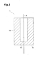
- Fig. 2 is a cross-sectional view showing the buncher 8.
- the buncher 8 has a cylindrical main body portion 8a and an electrode portion 8b that closes an opening of the cylindrical main body portion 8a on the inflector 9 side. That is, the electrode portion 8b is located at the end of the buncher 8 on the inflector 9 side.
- the main body portion 8a and the electrode portion 8b are an integral member.
- the main body portion 8a and the electrode portion 8b are formed of a conductive material, such as copper.
- the buncher 8 is disposed at a predetermined distance from the inflector 9. Specifically, it is preferable that the buncher 8 be disposed such that the distance between an end surface 8c on the inflector 9 side and the inflector 9 is 10 cm to 30 cm.
- the bunching effect of adjusting the density of the ion beamRbefore reaching the inflector 9 can be sufficiently obtained by separating the end surface 8c of the buncher 8 and the inflector 9 from each other by 10 cm or more.
- the distance between the end surface 8c of the buncher 8 and the inflector 9 is less than 30 cm, it is possible to reach the inflector 9 before the bunching effect is reduced by the space charge effect.
- a current is supplied from a power supply (not shown) to the buncher 8.
- the ion beam R travels through the inside of the cylindrical main body portion 8a and passes through the electrode portion 8b, thereby adjusting the density in the traveling direction.
- the ion beam R having passed through the buncher 8 travels toward the inflector 9.
- the structure of the buncher 8 is not limited to that described above.
- the electrode portion 8b may be provided not at the end of the main body portion 8a on the inflector 9 side but at the opposite end or in the middle of the main body portion 8a. In this case, it is preferable that the distance between the electrode portion 8b and the inflector 9 be 10 cm to 30 cm.
- the inflector 9 is for making the ion beam R incident on (introduced to) the median plane M.
- a current is supplied from a power supply (not shown) to the inflector 9, and the inflector 9 deflects the ion beam R traveling along the central axis C of the cyclotron 1 to make the ion beam R incident on the median plane M.
- the inflector 9 is disposed approximately at the center of the cyclotron 1 between the upper pole 6 and the lower pole 7.
- the ion beam R incident on the median plane M through the inflector 9 accelerates while drawing the spiral trajectory by the action of the magnetic field of the pole 4 and the electric field of the D electrode. After being sufficiently accelerated, the ion beam R is drawn from the trajectory and output to the outside.
- the buncher 8 is disposed in the yoke 3. Therefore, compared with a configuration in the related art in which the buncher 8 is provided outside the yoke 3, it is possible to reduce the distance between the buncher 8 and the inflector 9. For this reason, since the ion beam R can reach the inflector 9 before being spread by the space charge effect after adjusting the density of the ion beam R in the traveling direction (phase direction) using the buncher 8, it is possible to accelerate the ion beam R in a state having a high bunching effect. As a result, it is possible to improve the beam efficiency.
- the buncher 8 and the inflector 9 can be disposed so as to be appropriately distant from each other. As a result, it is possible to improve the beam efficiency.
- the ion beam R can reach the inflector 9 before being spread by the space charge effect, compared with a case where the electrode portion 8b is located in a portion other than the end on the inflector 9 side. This is advantageous in improving the beam efficiency.
- the present invention is not limited to the embodiment described above.
- the ion beam R may be incident from the bottom side of the yoke.
- a buncher is disposed in a lower hole of the yoke, and enters a recess formed in the lower pole.
- a buncher does not necessarily need to enter the recess formed in the upper pole or the lower pole.
- a buncher may be housed inside a hole formed in the yoke without reaching the upper pole or the lower pole.
- at least a part of the buncher may enter the yoke and the remaining portion may protrude outside the yoke.
- a second hole in which a buncher is not disposed does not necessarily need to be provided in the yoke.
- a recess does not necessarily need to be provided in one of the upper pole and the lower pole that a buncher does not enter.
- a vertical type cyclotron may also be adopted instead of the horizontal type cyclotron.
- the vertical direction in the explanation of the above embodiment becomes a horizontal direction
- the upper pole and the lower pole become a right pole and a left pole, respectively.
Landscapes
- Physics & Mathematics (AREA)
- Engineering & Computer Science (AREA)
- Plasma & Fusion (AREA)
- Spectroscopy & Molecular Physics (AREA)
- Particle Accelerators (AREA)
Abstract
Description
- The present invention relates to a cyclotron having a buncher.
- As a technical document regarding a cyclotron in the related art, for example, Japanese Unexamined Patent Application Publication No.
2004-31115 2004-31115 - Such a buncher is used for efficient acceleration of the ion beam in a high-frequency electric field. That is, since the potential difference changes periodically in a high-frequency electric field, a part where the ion beam accelerates due to the potential difference in a traveling direction (phase direction) and a part where the ion beam does not accelerate occur. For this reason, a buncher that adjusts the density of ion beams in the traveling direction so that the ion beams are focused on the acceleration part is provided in order to improve the beam efficiency.
- Incidentally, if the density of ion beams in the traveling direction is adjusted using the buncher, the bunching effect is reduced due to repulsion by the space charge effect between the focused ions. Such a space charge effect appears stronger as the current value of the ion beam becomes higher. Since the bunching effect is reduced due to the space charge effect, there has been a problem in that the beam efficiency is reduced in the cyclotron.
- Therefore, it is an object of the present invention to provide a cyclotron capable of improving the beam efficiency.
- In order to solve the above-described problem, according to an embodiment of the present invention, there is provided a cyclotron including: a hollow yoke; first and second poles disposed in the yoke; an ion source that generates an ion; a buncher of which at least a part enters the yoke and which adjusts a density of an ion beam, which is emitted from the ion source, in a traveling direction; and an inflector that deflects an ion beam having passed through the buncher to make the ion beam incident on a median plane.
- According to this cyclotron, since at least a part of the buncher enters the yoke, it is possible to reduce the distance between the buncher and the inflector, compared with a configuration in the related art in which a buncher is disposed outside a yoke. For this reason, since the ion beam can reach the inflector before the ion beam is spread by the space charge effect after adjusting the density of the ion beam in the traveling direction (phase direction) using the buncher, it is possible to accelerate the ion beam in a state having a high bunching effect. As a result, it is possible to improve the beam efficiency.
- In the cyclotron according to the embodiment of the present invention, at least a part of the buncher may enter the first pole.
- According to this cyclotron, since it is possible to further reduce the distance between the buncher and the inflector, the buncher and the inflector can be disposed so as to be appropriately close to each other even in the case of a large cyclotron. As a result, it is possible to improve the beam efficiency.
- In the cyclotron according to the embodiment of the present invention, an electrode portion of the buncher may be located at one end on the inflector side.
- According to this cyclotron, since the electrode portion that adj usts the density of the ion beam in the traveling direction is located at the end on the inflector side, the ion beam can reach the inflector before being spread by the space charge effect, compared with a case where the electrode portion is located in a portion other than the end on the inflector side. This is advantageous in improving the beam efficiency.
- In the cyclotron according to the embodiment of the present invention, the yoke may include a first hole that at least a part of the buncher enters and a second hole formed so as to be approximately symmetrical with the first hole with respect to the inflector.
- According to this cyclotron, compared with a case where the second hole is not provided, it is possible to maintain the symmetry of the yoke. Therefore, control of the magnetic field on the median plane becomes easy.
- According to the present invention, it is possible to provide a cyclotron capable of improving the beam efficiency.
-
-
Fig. 1 is a cross-sectional view showing a cyclotron according to an embodiment of the present invention. -
Fig. 2 is a cross-sectional view showing a buncher illustrated inFig. 1 . - Hereinafter, a preferred embodiment of the present invention will be described with reference to the drawings.
- As shown in
Fig. 1 , acyclotron 1 according to the present embodiment is a horizontal type accelerator that accelerates and emits an ion beam R emitted from anion source 2. As ions that form the ion beam R, for example, protons, heavy ions, and the like can be mentioned. - The
cyclotron 1 is used as a cyclotron for positron emission tomography (PET), a cyclotron for boron neutron capture therapy, a cyclotron for radio isotope (RI) formulation, a cyclotron for neutron sources, a cyclotron for protons, and a cyclotron for deuterons, for example. - The
cyclotron 1 includes theion source 2, ahollow yoke 3 in which predetermined space is formed, apole 4, acoil 5, abuncher 8, and aninflector 9. - The
ion source 2 is an external ion source that is provided outside theyoke 3 to generate ions. InFig. 1 , theion source 2 is provided on the central axis C of the disc-shaped cyclotron 1. However, theion source 2 does not necessarily need to be provided on the central axis C. Theion source 2 may be provided below thecyclotron 1 instead of being provided above thecyclotron 1. In addition, a part or theentire ion source 2 may be provided inside theyoke 3. - The
pole 4 is a pole including an upper pole (first pole) 6 and a lower pole (second pole) 7. Theupper pole 6 is disposed on anupper surface 3a inside theyoke 3, and thelower pole 7 is disposed on alower surface 3b inside theyoke 3. Theannular coil 5 is disposed around theupper pole 6 and thelower pole 7, and a magnetic field in a vertical direction is generated between theupper pole 6 and thelower pole 7 by current supply to thecoil 5. Between theupper pole 6 and thelower pole 7, a median plane M around which the ion beam R goes is formed. - In addition, the
cyclotron 1 includes a D electrode (not shown). The D electrode is formed in a fan shape when viewed from the extending direction of the central axis C. Inside the D electrode, a cavity penetrated in the circumferential direction of the central axis C is formed. The median plane M is located in the cavity. In thecyclotron 1, a high-frequency electric field is generated within the cavity by supplying an AC current to the D electrode, and the ion beam R is repeatedly accelerated by periodic change of the potential difference in the high-frequency electric field. - The
buncher 8 is used to adjust the density of the ion beam R in the traveling direction (phase direction). Thebuncher 8 increases the beam efficiency of thecyclotron 1 by focusing the ion beam R at predetermined intervals in the traveling direction so as to correspond to the periodic change of the potential difference in the high-frequency electric field. - The
buncher 8 is disposed in thehollow yoke 3. Specifically, thebuncher 8 is disposed inside afirst hole 3c for a buncher formed in theyoke 3. Thefirst hole 3c is a through hole formed along the central axis C so as to allow communication between the space inside theyoke 3 and the outside of theyoke 3. The ion beam R emitted from theion source 2 reaches thebuncher 8 through thefirst hole 3c. - In addition, a part of the
buncher 8 enters arecess 6a formed in theupper pole 6. That is, most of thebuncher 8 is housed in thefirst hole 3c of theyoke 3, and a part of the buncher 8 (on theupper pole 6 side) enters therecess 6a of theupper pole 6. Therecess 6a of theupper pole 6 is formed so as to correspond to thefirst hole 3c of theyoke 3, and is recessed downward along the central axis C. - In addition, the
yoke 3 has asecond hole 3e formed on the opposite side of thefirst hole 3c with respect to theinflector 9. Thesecond hole 3e is a through hole formed so as to be approximately symmetrical with thefirst hole 3c with respect to theinflector 9. That is, in order to maintain the symmetry of theyoke 3, thesecond hole 3e is formed so as to have the same size and shape as thefirst hole 3c if possible. - Similarly, the
lower pole 7 has arecess 7a formed so as to be approximately symmetrical with therecess 6a of theupper pole 6 with respect to theinflector 9. Therecess 7a is formed so as to correspond to thesecond hole 3e of theyoke 3, and is recessed upward along the central axis C. -
Fig. 2 is a cross-sectional view showing thebuncher 8. As shown inFig. 2 , thebuncher 8 has a cylindricalmain body portion 8a and anelectrode portion 8b that closes an opening of the cylindricalmain body portion 8a on theinflector 9 side. That is, theelectrode portion 8b is located at the end of thebuncher 8 on theinflector 9 side. Themain body portion 8a and theelectrode portion 8b are an integral member. For example, themain body portion 8a and theelectrode portion 8b are formed of a conductive material, such as copper. - The
buncher 8 is disposed at a predetermined distance from theinflector 9. Specifically, it is preferable that thebuncher 8 be disposed such that the distance between anend surface 8c on theinflector 9 side and theinflector 9 is 10 cm to 30 cm. - The bunching effect of adjusting the density of the ion beamRbefore reaching the
inflector 9 can be sufficiently obtained by separating theend surface 8c of thebuncher 8 and theinflector 9 from each other by 10 cm or more. In addition, since the distance between theend surface 8c of thebuncher 8 and theinflector 9 is less than 30 cm, it is possible to reach theinflector 9 before the bunching effect is reduced by the space charge effect. - A current is supplied from a power supply (not shown) to the
buncher 8. The ion beam R travels through the inside of the cylindricalmain body portion 8a and passes through theelectrode portion 8b, thereby adjusting the density in the traveling direction. The ion beam R having passed through thebuncher 8 travels toward theinflector 9. - In addition, the structure of the
buncher 8 is not limited to that described above. For example, theelectrode portion 8b may be provided not at the end of themain body portion 8a on theinflector 9 side but at the opposite end or in the middle of themain body portion 8a. In this case, it is preferable that the distance between theelectrode portion 8b and theinflector 9 be 10 cm to 30 cm. - The
inflector 9 is for making the ion beam R incident on (introduced to) the median plane M. A current is supplied from a power supply (not shown) to theinflector 9, and theinflector 9 deflects the ion beam R traveling along the central axis C of thecyclotron 1 to make the ion beam R incident on the median plane M. Theinflector 9 is disposed approximately at the center of thecyclotron 1 between theupper pole 6 and thelower pole 7. - The ion beam R incident on the median plane M through the
inflector 9 accelerates while drawing the spiral trajectory by the action of the magnetic field of thepole 4 and the electric field of the D electrode. After being sufficiently accelerated, the ion beam R is drawn from the trajectory and output to the outside. - In the
cyclotron 1 according to the present embodiment described above, thebuncher 8 is disposed in theyoke 3. Therefore, compared with a configuration in the related art in which thebuncher 8 is provided outside theyoke 3, it is possible to reduce the distance between thebuncher 8 and theinflector 9. For this reason, since the ion beam R can reach theinflector 9 before being spread by the space charge effect after adjusting the density of the ion beam R in the traveling direction (phase direction) using thebuncher 8, it is possible to accelerate the ion beam R in a state having a high bunching effect. As a result, it is possible to improve the beam efficiency. - In addition, in the
cyclotron 1, since a part of thebuncher 8 enters therecess 6a of theupper pole 6, it is possible to further reduce the distance between thebuncher 8 and theinflector 9. Therefore, according to thecyclotron 1, even in the case of a large cyclotron, thebuncher 8 and theinflector 9 can be disposed so as to be appropriately distant from each other. As a result, it is possible to improve the beam efficiency. - In addition, according to the
cyclotron 1, since theelectrode portion 8b of thebuncher 8 is located at the end of themain body portion 8a on theinflector 9 side, the ion beam R can reach theinflector 9 before being spread by the space charge effect, compared with a case where theelectrode portion 8b is located in a portion other than the end on theinflector 9 side. This is advantageous in improving the beam efficiency. - In addition, in the
cyclotron 1, since thesecond hole 3e formed on the opposite side of thefirst hole 3c with respect to theinflector 9 is provided, it is possible to maintain the symmetry of theyoke 3 compared with a case where thesecond hole 3e is not provided. Accordingly, control of the magnetic field on the median plane M becomes easy. - The present invention is not limited to the embodiment described above. For example, the ion beam R may be incident from the bottom side of the yoke. In this case, a buncher is disposed in a lower hole of the yoke, and enters a recess formed in the lower pole.
- In addition, a buncher does not necessarily need to enter the recess formed in the upper pole or the lower pole. A buncher may be housed inside a hole formed in the yoke without reaching the upper pole or the lower pole. In addition, at least a part of the buncher may enter the yoke and the remaining portion may protrude outside the yoke.
- In addition, a second hole in which a buncher is not disposed does not necessarily need to be provided in the yoke. Similarly, a recess does not necessarily need to be provided in one of the upper pole and the lower pole that a buncher does not enter.
- In addition, a vertical type cyclotron may also be adopted instead of the horizontal type cyclotron. In this case, the vertical direction in the explanation of the above embodiment becomes a horizontal direction, and the upper pole and the lower pole become a right pole and a left pole, respectively.
Claims (4)
- A cyclotron, comprising:a hollow yoke;first and second poles disposed in the yoke;an ion source that generates an ion;a buncher of which at least a part enters the yoke and which adjusts a density of an ion beam, which is emitted from the ion source, in a traveling direction; andan inflector that deflects an ion beam having passed through the buncher to make the ion beam incident on a median plane.
- The cyclotron according to claim 1,
wherein at least a part of the buncher enters the first pole. - The cyclotron according to claim 1,
wherein an electrode portion of the buncher is located at one end on the inflector side. - The cyclotron according to claim 1,
wherein the yoke includes a first hole that at least a part of the buncher enters and a second hole formed so as to be approximately symmetrical with the first hole with respect to the inflector.
Applications Claiming Priority (1)
| Application Number | Priority Date | Filing Date | Title |
|---|---|---|---|
| JP2012254346A JP2014102990A (en) | 2012-11-20 | 2012-11-20 | Cyclotron |
Publications (2)
| Publication Number | Publication Date |
|---|---|
| EP2734017A1 true EP2734017A1 (en) | 2014-05-21 |
| EP2734017B1 EP2734017B1 (en) | 2018-06-13 |
Family
ID=49354426
Family Applications (1)
| Application Number | Title | Priority Date | Filing Date |
|---|---|---|---|
| EP13004888.7A Not-in-force EP2734017B1 (en) | 2012-11-20 | 2013-10-11 | Cyclotron |
Country Status (6)
| Country | Link |
|---|---|
| US (1) | US9000657B2 (en) |
| EP (1) | EP2734017B1 (en) |
| JP (1) | JP2014102990A (en) |
| KR (1) | KR20140064609A (en) |
| CN (1) | CN103841745B (en) |
| TW (1) | TWI523585B (en) |
Cited By (1)
| Publication number | Priority date | Publication date | Assignee | Title |
|---|---|---|---|---|
| CN108883304A (en) * | 2018-06-22 | 2018-11-23 | 新瑞阳光粒子医疗装备(无锡)有限公司 | Synchrotron control method, device, equipment and storage medium |
Families Citing this family (7)
| Publication number | Priority date | Publication date | Assignee | Title |
|---|---|---|---|---|
| JP5955709B2 (en) * | 2012-09-04 | 2016-07-20 | 住友重機械工業株式会社 | cyclotron |
| EP2811813B1 (en) * | 2013-06-04 | 2016-01-06 | Ion Beam Applications | Methods for adjusting the position of a main coil in a cyclotron |
| CN109874222B (en) * | 2017-12-06 | 2022-10-25 | 清华大学 | Drift tube, drift tube linear accelerator and drift tube processing method |
| KR102238857B1 (en) * | 2019-01-29 | 2021-04-09 | 성균관대학교산학협력단 | Accelerated Mass Spectrometry Cyclotron System |
| JP7458309B2 (en) * | 2020-12-11 | 2024-03-29 | 株式会社日立製作所 | Laser ion sources, circular accelerators and particle therapy systems |
| TWI895780B (en) | 2022-10-06 | 2025-09-01 | 禾榮科技股份有限公司 | Superconducting electromagnet component and isochronous cyclotron including the same |
| CN116156730B (en) * | 2023-01-09 | 2023-11-21 | 中国科学院近代物理研究所 | Structure of axial injector for cyclotron |
Citations (1)
| Publication number | Priority date | Publication date | Assignee | Title |
|---|---|---|---|---|
| JP2004031115A (en) | 2002-06-26 | 2004-01-29 | Matsushita Electric Ind Co Ltd | Method and apparatus for limiting phase width of beam accelerated by cyclotron |
Family Cites Families (12)
| Publication number | Priority date | Publication date | Assignee | Title |
|---|---|---|---|---|
| GB2186736A (en) * | 1986-02-13 | 1987-08-19 | Marconi Co Ltd | Ion beam arrangement |
| US5227701A (en) * | 1988-05-18 | 1993-07-13 | Mcintyre Peter M | Gigatron microwave amplifier |
| BE1005530A4 (en) * | 1991-11-22 | 1993-09-28 | Ion Beam Applic Sa | Cyclotron isochronous |
| JP2925965B2 (en) | 1994-12-15 | 1999-07-28 | 住友重機械工業株式会社 | Method and apparatus for collecting charged particle beams |
| USH1758H (en) * | 1996-03-04 | 1998-11-03 | Malouf; Perry M. | Microwave amplifier having cross-polarized cavities |
| WO2000036633A1 (en) * | 1998-12-17 | 2000-06-22 | Jeol Usa, Inc. | In-line reflecting time-of-flight mass spectrometer for molecular structural analysis using collision induced dissociation |
| WO2002015218A1 (en) * | 2000-08-17 | 2002-02-21 | Gesellschaft für Schwerionenforschung mbH | Device and method for ion beam acceleration and electron beam pulse formation and amplification |
| CN101061759B (en) * | 2004-07-21 | 2011-05-25 | 斯蒂尔瑞弗系统有限公司 | Programmable RF Waveform Generator for Synchrocyclotrons |
| US7315140B2 (en) * | 2005-01-27 | 2008-01-01 | Matsushita Electric Industrial Co., Ltd. | Cyclotron with beam phase selector |
| US7888630B2 (en) * | 2006-04-06 | 2011-02-15 | Wong Alfred Y | Reduced size high frequency quadrupole accelerator for producing a neutralized ion beam of high energy |
| US7919765B2 (en) * | 2008-03-20 | 2011-04-05 | Varian Medical Systems Particle Therapy Gmbh | Non-continuous particle beam irradiation method and apparatus |
| US8106570B2 (en) * | 2009-05-05 | 2012-01-31 | General Electric Company | Isotope production system and cyclotron having reduced magnetic stray fields |
-
2012
- 2012-11-20 JP JP2012254346A patent/JP2014102990A/en active Pending
-
2013
- 2013-08-05 KR KR1020130092515A patent/KR20140064609A/en not_active Ceased
- 2013-08-06 TW TW102128112A patent/TWI523585B/en not_active IP Right Cessation
- 2013-08-13 CN CN201310351163.XA patent/CN103841745B/en not_active Expired - Fee Related
- 2013-10-11 EP EP13004888.7A patent/EP2734017B1/en not_active Not-in-force
- 2013-10-15 US US14/053,734 patent/US9000657B2/en not_active Expired - Fee Related
Patent Citations (1)
| Publication number | Priority date | Publication date | Assignee | Title |
|---|---|---|---|---|
| JP2004031115A (en) | 2002-06-26 | 2004-01-29 | Matsushita Electric Ind Co Ltd | Method and apparatus for limiting phase width of beam accelerated by cyclotron |
Non-Patent Citations (5)
| Title |
|---|
| B.GIKAL ET AL: "Recent Developments at Dubna U400 and U400M Cyclotrons", PROCEEDINGS OF CYCLOTRONS'98, 1998, pages 587 - 591, XP002719638 * |
| L.M.ONISCHENKO ET AL: "Development of Compact Cyclotron for Explosives Detection by Nuclear Resonance Absorption of Gamma-rays in Nitrogen", PROCEEDINGS OF RUPAC XIX, DUBNA 2004, 2004, pages 126 - 128, XP002719635 * |
| P.HEIKKINEN ET AL: "Ion Optics in the Jyväskylä K130 Cyclotron", PROCEEDINGS OF CYCLOTRONS'92, 1992, pages 392 - 395, XP002719637 * |
| R.K.BHANDARI ET AL: "The Beam Handling and Axial Injection System for the Project ISIS at JULIC", PROCEEDINGS OF CYCLOTRONS'81, 1981, pages 261 - 265, XP002719636 * |
| R.W.HAMM ET AL: "Use of the Radio-frequency Quadrupole Structure as a Cyclotron Axial Buncher System", PROCEEDINGS OF CYCLOTRONS'81, 1981, pages 359 - 363, XP002719639 * |
Cited By (2)
| Publication number | Priority date | Publication date | Assignee | Title |
|---|---|---|---|---|
| CN108883304A (en) * | 2018-06-22 | 2018-11-23 | 新瑞阳光粒子医疗装备(无锡)有限公司 | Synchrotron control method, device, equipment and storage medium |
| CN108883304B (en) * | 2018-06-22 | 2020-08-07 | 新瑞阳光粒子医疗装备(无锡)有限公司 | Synchrotron control method, device and storage medium |
Also Published As
| Publication number | Publication date |
|---|---|
| US9000657B2 (en) | 2015-04-07 |
| TWI523585B (en) | 2016-02-21 |
| TW201422062A (en) | 2014-06-01 |
| CN103841745A (en) | 2014-06-04 |
| EP2734017B1 (en) | 2018-06-13 |
| CN103841745B (en) | 2016-12-28 |
| KR20140064609A (en) | 2014-05-28 |
| JP2014102990A (en) | 2014-06-05 |
| US20140139096A1 (en) | 2014-05-22 |
Similar Documents
| Publication | Publication Date | Title |
|---|---|---|
| US9000657B2 (en) | Cyclotron | |
| JP4719241B2 (en) | Circular accelerator | |
| Skalyga et al. | New progress of high current gasdynamic ion source | |
| JP6289728B2 (en) | Injector system for synchrotron and operation method of drift tube linear accelerator | |
| EP3180966A1 (en) | High frequency compact low-energy linear accelerator design | |
| US9805901B2 (en) | Compact magnet design for high-power magnetrons | |
| US12324088B2 (en) | Ion source, circular accelerator using same, and particle beam therapy system | |
| US10850132B2 (en) | Particle therapy system | |
| MX359737B (en) | Nano-emitter ion source neutron generator. | |
| JP2014102990A5 (en) | ||
| CN111630940A (en) | Accelerators and Accelerator Systems | |
| CN207802493U (en) | Petal-shaped accelerator and its c-type connector motor magnet | |
| KR101378384B1 (en) | Cyclotron | |
| JP2006278006A (en) | Plasma interface control method and ion source in ion source extraction region | |
| Bryzgunov et al. | Efficiency improvement of an electron collector intended for electron cooling systems using a Wien filter | |
| Polozov et al. | Beam dynamics study and electrodynamics simulations for the cw RFQ | |
| JP6121186B2 (en) | Bunchers and accelerators | |
| CN116417317A (en) | A Structure for Improving the Acceleration Efficiency of Radio Frequency Acceleration Barrel in Ion Implantation System | |
| JP2012142139A (en) | Ion beam generation method and ion beam generation apparatus | |
| JP6042226B2 (en) | Accelerator and Neutron Capture Therapy Device | |
| CN119383815B (en) | Method, system, equipment and storage medium for fast and slow extraction of automatic resonance of synchrotron | |
| JP5622225B2 (en) | Beam control apparatus, particle beam irradiation apparatus, and control method thereof | |
| JP7176982B2 (en) | Neutron generator and neutron generation method | |
| WO2018092483A1 (en) | Accelerator, particle beam irradiation device, and method for extracting beam | |
| JP2017216190A (en) | Accelerator and particle beam irradiation device |
Legal Events
| Date | Code | Title | Description |
|---|---|---|---|
| PUAI | Public reference made under article 153(3) epc to a published international application that has entered the european phase |
Free format text: ORIGINAL CODE: 0009012 |
|
| 17P | Request for examination filed |
Effective date: 20131011 |
|
| AK | Designated contracting states |
Kind code of ref document: A1 Designated state(s): AL AT BE BG CH CY CZ DE DK EE ES FI FR GB GR HR HU IE IS IT LI LT LU LV MC MK MT NL NO PL PT RO RS SE SI SK SM TR |
|
| AX | Request for extension of the european patent |
Extension state: BA ME |
|
| R17P | Request for examination filed (corrected) |
Effective date: 20141119 |
|
| RBV | Designated contracting states (corrected) |
Designated state(s): AL AT BE BG CH CY CZ DE DK EE ES FI FR GB GR HR HU IE IS IT LI LT LU LV MC MK MT NL NO PL PT RO RS SE SI SK SM TR |
|
| GRAP | Despatch of communication of intention to grant a patent |
Free format text: ORIGINAL CODE: EPIDOSNIGR1 |
|
| RIC1 | Information provided on ipc code assigned before grant |
Ipc: H05H 13/00 20060101AFI20171214BHEP |
|
| INTG | Intention to grant announced |
Effective date: 20180105 |
|
| GRAS | Grant fee paid |
Free format text: ORIGINAL CODE: EPIDOSNIGR3 |
|
| GRAA | (expected) grant |
Free format text: ORIGINAL CODE: 0009210 |
|
| AK | Designated contracting states |
Kind code of ref document: B1 Designated state(s): AL AT BE BG CH CY CZ DE DK EE ES FI FR GB GR HR HU IE IS IT LI LT LU LV MC MK MT NL NO PL PT RO RS SE SI SK SM TR |
|
| REG | Reference to a national code |
Ref country code: GB Ref legal event code: FG4D |
|
| REG | Reference to a national code |
Ref country code: CH Ref legal event code: EP Ref country code: AT Ref legal event code: REF Ref document number: 1009878 Country of ref document: AT Kind code of ref document: T Effective date: 20180615 |
|
| REG | Reference to a national code |
Ref country code: DE Ref legal event code: R096 Ref document number: 602013038766 Country of ref document: DE |
|
| REG | Reference to a national code |
Ref country code: IE Ref legal event code: FG4D |
|
| REG | Reference to a national code |
Ref country code: NL Ref legal event code: MP Effective date: 20180613 |
|
| REG | Reference to a national code |
Ref country code: LT Ref legal event code: MG4D |
|
| PG25 | Lapsed in a contracting state [announced via postgrant information from national office to epo] |
Ref country code: NO Free format text: LAPSE BECAUSE OF FAILURE TO SUBMIT A TRANSLATION OF THE DESCRIPTION OR TO PAY THE FEE WITHIN THE PRESCRIBED TIME-LIMIT Effective date: 20180913 Ref country code: BG Free format text: LAPSE BECAUSE OF FAILURE TO SUBMIT A TRANSLATION OF THE DESCRIPTION OR TO PAY THE FEE WITHIN THE PRESCRIBED TIME-LIMIT Effective date: 20180913 Ref country code: CY Free format text: LAPSE BECAUSE OF FAILURE TO SUBMIT A TRANSLATION OF THE DESCRIPTION OR TO PAY THE FEE WITHIN THE PRESCRIBED TIME-LIMIT Effective date: 20180613 Ref country code: LT Free format text: LAPSE BECAUSE OF FAILURE TO SUBMIT A TRANSLATION OF THE DESCRIPTION OR TO PAY THE FEE WITHIN THE PRESCRIBED TIME-LIMIT Effective date: 20180613 Ref country code: ES Free format text: LAPSE BECAUSE OF FAILURE TO SUBMIT A TRANSLATION OF THE DESCRIPTION OR TO PAY THE FEE WITHIN THE PRESCRIBED TIME-LIMIT Effective date: 20180613 Ref country code: SE Free format text: LAPSE BECAUSE OF FAILURE TO SUBMIT A TRANSLATION OF THE DESCRIPTION OR TO PAY THE FEE WITHIN THE PRESCRIBED TIME-LIMIT Effective date: 20180613 |
|
| PG25 | Lapsed in a contracting state [announced via postgrant information from national office to epo] |
Ref country code: LV Free format text: LAPSE BECAUSE OF FAILURE TO SUBMIT A TRANSLATION OF THE DESCRIPTION OR TO PAY THE FEE WITHIN THE PRESCRIBED TIME-LIMIT Effective date: 20180613 Ref country code: HR Free format text: LAPSE BECAUSE OF FAILURE TO SUBMIT A TRANSLATION OF THE DESCRIPTION OR TO PAY THE FEE WITHIN THE PRESCRIBED TIME-LIMIT Effective date: 20180613 Ref country code: RS Free format text: LAPSE BECAUSE OF FAILURE TO SUBMIT A TRANSLATION OF THE DESCRIPTION OR TO PAY THE FEE WITHIN THE PRESCRIBED TIME-LIMIT Effective date: 20180613 Ref country code: GR Free format text: LAPSE BECAUSE OF FAILURE TO SUBMIT A TRANSLATION OF THE DESCRIPTION OR TO PAY THE FEE WITHIN THE PRESCRIBED TIME-LIMIT Effective date: 20180914 |
|
| REG | Reference to a national code |
Ref country code: AT Ref legal event code: MK05 Ref document number: 1009878 Country of ref document: AT Kind code of ref document: T Effective date: 20180613 |
|
| PG25 | Lapsed in a contracting state [announced via postgrant information from national office to epo] |
Ref country code: NL Free format text: LAPSE BECAUSE OF FAILURE TO SUBMIT A TRANSLATION OF THE DESCRIPTION OR TO PAY THE FEE WITHIN THE PRESCRIBED TIME-LIMIT Effective date: 20180613 |
|
| PG25 | Lapsed in a contracting state [announced via postgrant information from national office to epo] |
Ref country code: IS Free format text: LAPSE BECAUSE OF FAILURE TO SUBMIT A TRANSLATION OF THE DESCRIPTION OR TO PAY THE FEE WITHIN THE PRESCRIBED TIME-LIMIT Effective date: 20181013 Ref country code: SK Free format text: LAPSE BECAUSE OF FAILURE TO SUBMIT A TRANSLATION OF THE DESCRIPTION OR TO PAY THE FEE WITHIN THE PRESCRIBED TIME-LIMIT Effective date: 20180613 Ref country code: PL Free format text: LAPSE BECAUSE OF FAILURE TO SUBMIT A TRANSLATION OF THE DESCRIPTION OR TO PAY THE FEE WITHIN THE PRESCRIBED TIME-LIMIT Effective date: 20180613 Ref country code: CZ Free format text: LAPSE BECAUSE OF FAILURE TO SUBMIT A TRANSLATION OF THE DESCRIPTION OR TO PAY THE FEE WITHIN THE PRESCRIBED TIME-LIMIT Effective date: 20180613 Ref country code: RO Free format text: LAPSE BECAUSE OF FAILURE TO SUBMIT A TRANSLATION OF THE DESCRIPTION OR TO PAY THE FEE WITHIN THE PRESCRIBED TIME-LIMIT Effective date: 20180613 Ref country code: AT Free format text: LAPSE BECAUSE OF FAILURE TO SUBMIT A TRANSLATION OF THE DESCRIPTION OR TO PAY THE FEE WITHIN THE PRESCRIBED TIME-LIMIT Effective date: 20180613 Ref country code: EE Free format text: LAPSE BECAUSE OF FAILURE TO SUBMIT A TRANSLATION OF THE DESCRIPTION OR TO PAY THE FEE WITHIN THE PRESCRIBED TIME-LIMIT Effective date: 20180613 |
|
| PG25 | Lapsed in a contracting state [announced via postgrant information from national office to epo] |
Ref country code: IT Free format text: LAPSE BECAUSE OF FAILURE TO SUBMIT A TRANSLATION OF THE DESCRIPTION OR TO PAY THE FEE WITHIN THE PRESCRIBED TIME-LIMIT Effective date: 20180613 Ref country code: SM Free format text: LAPSE BECAUSE OF FAILURE TO SUBMIT A TRANSLATION OF THE DESCRIPTION OR TO PAY THE FEE WITHIN THE PRESCRIBED TIME-LIMIT Effective date: 20180613 |
|
| REG | Reference to a national code |
Ref country code: DE Ref legal event code: R097 Ref document number: 602013038766 Country of ref document: DE |
|
| PLBE | No opposition filed within time limit |
Free format text: ORIGINAL CODE: 0009261 |
|
| STAA | Information on the status of an ep patent application or granted ep patent |
Free format text: STATUS: NO OPPOSITION FILED WITHIN TIME LIMIT |
|
| 26N | No opposition filed |
Effective date: 20190314 |
|
| PG25 | Lapsed in a contracting state [announced via postgrant information from national office to epo] |
Ref country code: SI Free format text: LAPSE BECAUSE OF FAILURE TO SUBMIT A TRANSLATION OF THE DESCRIPTION OR TO PAY THE FEE WITHIN THE PRESCRIBED TIME-LIMIT Effective date: 20180613 Ref country code: DK Free format text: LAPSE BECAUSE OF FAILURE TO SUBMIT A TRANSLATION OF THE DESCRIPTION OR TO PAY THE FEE WITHIN THE PRESCRIBED TIME-LIMIT Effective date: 20180613 |
|
| REG | Reference to a national code |
Ref country code: CH Ref legal event code: PL |
|
| GBPC | Gb: european patent ceased through non-payment of renewal fee |
Effective date: 20181011 |
|
| REG | Reference to a national code |
Ref country code: BE Ref legal event code: MM Effective date: 20181031 |
|
| PG25 | Lapsed in a contracting state [announced via postgrant information from national office to epo] |
Ref country code: LU Free format text: LAPSE BECAUSE OF NON-PAYMENT OF DUE FEES Effective date: 20181011 Ref country code: MC Free format text: LAPSE BECAUSE OF FAILURE TO SUBMIT A TRANSLATION OF THE DESCRIPTION OR TO PAY THE FEE WITHIN THE PRESCRIBED TIME-LIMIT Effective date: 20180613 |
|
| REG | Reference to a national code |
Ref country code: IE Ref legal event code: MM4A |
|
| PG25 | Lapsed in a contracting state [announced via postgrant information from national office to epo] |
Ref country code: LI Free format text: LAPSE BECAUSE OF NON-PAYMENT OF DUE FEES Effective date: 20181031 Ref country code: CH Free format text: LAPSE BECAUSE OF NON-PAYMENT OF DUE FEES Effective date: 20181031 Ref country code: FR Free format text: LAPSE BECAUSE OF NON-PAYMENT OF DUE FEES Effective date: 20181031 Ref country code: BE Free format text: LAPSE BECAUSE OF NON-PAYMENT OF DUE FEES Effective date: 20181031 |
|
| PG25 | Lapsed in a contracting state [announced via postgrant information from national office to epo] |
Ref country code: IE Free format text: LAPSE BECAUSE OF NON-PAYMENT OF DUE FEES Effective date: 20181011 Ref country code: GB Free format text: LAPSE BECAUSE OF NON-PAYMENT OF DUE FEES Effective date: 20181011 |
|
| PG25 | Lapsed in a contracting state [announced via postgrant information from national office to epo] |
Ref country code: AL Free format text: LAPSE BECAUSE OF FAILURE TO SUBMIT A TRANSLATION OF THE DESCRIPTION OR TO PAY THE FEE WITHIN THE PRESCRIBED TIME-LIMIT Effective date: 20180613 |
|
| PG25 | Lapsed in a contracting state [announced via postgrant information from national office to epo] |
Ref country code: MT Free format text: LAPSE BECAUSE OF NON-PAYMENT OF DUE FEES Effective date: 20181011 |
|
| PG25 | Lapsed in a contracting state [announced via postgrant information from national office to epo] |
Ref country code: TR Free format text: LAPSE BECAUSE OF FAILURE TO SUBMIT A TRANSLATION OF THE DESCRIPTION OR TO PAY THE FEE WITHIN THE PRESCRIBED TIME-LIMIT Effective date: 20180613 |
|
| PG25 | Lapsed in a contracting state [announced via postgrant information from national office to epo] |
Ref country code: PT Free format text: LAPSE BECAUSE OF FAILURE TO SUBMIT A TRANSLATION OF THE DESCRIPTION OR TO PAY THE FEE WITHIN THE PRESCRIBED TIME-LIMIT Effective date: 20180613 |
|
| PG25 | Lapsed in a contracting state [announced via postgrant information from national office to epo] |
Ref country code: HU Free format text: LAPSE BECAUSE OF FAILURE TO SUBMIT A TRANSLATION OF THE DESCRIPTION OR TO PAY THE FEE WITHIN THE PRESCRIBED TIME-LIMIT; INVALID AB INITIO Effective date: 20131011 Ref country code: MK Free format text: LAPSE BECAUSE OF NON-PAYMENT OF DUE FEES Effective date: 20180613 |
|
| PGFP | Annual fee paid to national office [announced via postgrant information from national office to epo] |
Ref country code: DE Payment date: 20210831 Year of fee payment: 9 Ref country code: FI Payment date: 20211011 Year of fee payment: 9 |
|
| REG | Reference to a national code |
Ref country code: DE Ref legal event code: R119 Ref document number: 602013038766 Country of ref document: DE |
|
| PG25 | Lapsed in a contracting state [announced via postgrant information from national office to epo] |
Ref country code: DE Free format text: LAPSE BECAUSE OF NON-PAYMENT OF DUE FEES Effective date: 20230503 |
|
| PG25 | Lapsed in a contracting state [announced via postgrant information from national office to epo] |
Ref country code: FI Free format text: LAPSE BECAUSE OF NON-PAYMENT OF DUE FEES Effective date: 20221011 |