EP2733848A1 - Automatic quadrature network with phase and amplitude detection - Google Patents
Automatic quadrature network with phase and amplitude detection Download PDFInfo
- Publication number
- EP2733848A1 EP2733848A1 EP13193411.9A EP13193411A EP2733848A1 EP 2733848 A1 EP2733848 A1 EP 2733848A1 EP 13193411 A EP13193411 A EP 13193411A EP 2733848 A1 EP2733848 A1 EP 2733848A1
- Authority
- EP
- European Patent Office
- Prior art keywords
- quadrature
- signals
- amplitude
- phase
- output
- Prior art date
- Legal status (The legal status is an assumption and is not a legal conclusion. Google has not performed a legal analysis and makes no representation as to the accuracy of the status listed.)
- Withdrawn
Links
Images


Classifications
-
- H—ELECTRICITY
- H03—ELECTRONIC CIRCUITRY
- H03H—IMPEDANCE NETWORKS, e.g. RESONANT CIRCUITS; RESONATORS
- H03H11/00—Networks using active elements
- H03H11/02—Multiple-port networks
- H03H11/16—Networks for phase shifting
- H03H11/20—Two-port phase shifters providing an adjustable phase shift
-
- H—ELECTRICITY
- H03—ELECTRONIC CIRCUITRY
- H03H—IMPEDANCE NETWORKS, e.g. RESONANT CIRCUITS; RESONATORS
- H03H11/00—Networks using active elements
- H03H11/02—Multiple-port networks
- H03H11/16—Networks for phase shifting
- H03H11/22—Networks for phase shifting providing two or more phase shifted output signals, e.g. n-phase output
Definitions
- Quadrature (I/Q) frequency converters rely on having a pair of mixers which are driven by a quadrature local oscillator signal, i.e., two signals of the same frequency, but ninety degrees out of phase.
- a quadrature local oscillator signal i.e., two signals of the same frequency, but ninety degrees out of phase.
- One of the simpler methods of achieving the desired result is to input a single frequency to a quadrature network having two phase shifting paths, one path with a series resistor followed by a shunt capacitance (RC), and the other path with a series capacitance followed by a shunt resistance (CR). If the resistances are equal and the capacitances are equal, then there is a particular frequency for the single frequency input where the outputs of the two paths are of equal amplitude and in quadrature phase. Outside of the particular frequency, while the phase relationship is held, the amplitudes may vary.
Landscapes
- Digital Transmission Methods That Use Modulated Carrier Waves (AREA)
- Networks Using Active Elements (AREA)
- Stabilization Of Oscillater, Synchronisation, Frequency Synthesizers (AREA)
Abstract
Description
- The present invention relates to quadrature frequency converters, and more particularly to an automatic quadrature network with phase and amplitude detection to eliminate both phase and amplitude errors in a frequency converter output.
- Quadrature (I/Q) frequency converters rely on having a pair of mixers which are driven by a quadrature local oscillator signal, i.e., two signals of the same frequency, but ninety degrees out of phase. One of the simpler methods of achieving the desired result is to input a single frequency to a quadrature network having two phase shifting paths, one path with a series resistor followed by a shunt capacitance (RC), and the other path with a series capacitance followed by a shunt resistance (CR). If the resistances are equal and the capacitances are equal, then there is a particular frequency for the single frequency input where the outputs of the two paths are of equal amplitude and in quadrature phase. Outside of the particular frequency, while the phase relationship is held, the amplitudes may vary.
- One method of generating quadrature signals from a local oscillator (LO) uses amplitude detectors and a feedback control loop which adjusts either resistance or capacitance values in the RC and CR paths until the quadrature signals are matched in amplitude. This method is illustrated by
U.S. Patent No. 5,644,260 (DaSilva ) andG.B. Patent No. 1,345,274 (Ratzel Fig. 1 is a graphic representation of the DaSilva implementation, which shows that at the specified frequency - 100 MHz - the quadrature signals are equal in amplitude, but the phase differential between the two quadrature signals varies across the frequency spectrum - in this example at the LO frequency of 100 MHz the phase difference is 100° instead of 90°. In order to achieve the proper phase relationship, a static Vcal signal is used in conjunction with the detected amplitudes, the Vcal signal being selected from a table for the frequency of the particular local oscillator signal input. However, the Vcal signal cannot account for dynamic changes to the network due to time and temperature, so the network needs either frequent calibration or always has some phase error present. - An alternative method, if amplitude matching is not important, uses a phase detector and feedback loop to adjust one quadrature (RC) path or the other quadrature (CR) path until perfect phase quadrature is achieved, as illustrated by
U.S. Patent No. 4,908,532 (Chadwick ). Ignoring amplitude matching, however, may cause amplitude errors, even though the signal is passed through limiting stages. Because the phase difference may be 90° over a wide range of amplitude differences, one side or the other might be so starved of signal that the limiting amplifiers cannot limit. This causes poor match between the two mixers, since the local oscillator level is not the same at the inputs to the mixers. - What is desired is an automatic quadrature network for a quadrature frequency converter that provides equal amplitude and ideal quadrature phase for quadrature signals derived from a local oscillator.
- Accordingly, the present invention provides an automatic quadrature network with phase and amplitude detection that provides equal amplitude and ideal quadrature phase for quadrature signals derived from a local oscillator. An RC circuit provides one quadrature path, and a CR circuit provides another quadrature path. The outputs from the RC/CR circuits are amplitude detected to produce an amplitude control signal. The outputs also are amplitude limited, and the phase between the outputs at the limiter outputs is detected to produce a phase control signal. The amplitude and phase control signals are combined to generate respective control signals for the RC/CR circuits to automatically align the RC/CR circuits so that the quadrature signals are of equal amplitude and ideal quadrature phase.
- The objects, advantages and other novel features of the present invention are apparent from the following detailed description when read in conjunction with the attached drawing figures and claims.
-
-
Fig. 1 is a graphic illustration of one prior art method of assuring equal amplitude quadrature signals for an input local oscillator signal, but not ideal phase quadrature. -
Fig. 2 is a block diagram view of an automatic quadrature network according to the present invention. -
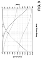
Fig. 3 is a graphic illustration of the quadrature outputs from the automatic quadrature network according to the present invention. - Referring now to
Fig. 2 , a local oscillator signal is input to a pair of paths, one path (RC) having afirst variable resistor 12 in series with afirst capacitor 14 to ground, and the other path (CR) having asecond capacitor 16 in series with a second variable resistor 18 to ground. The resistor/capacitor junctions of the respective paths are coupled to inputs of respective bufferinglinear amplifier stages amplifier stages diode peak detectors diode peak detectors amplifier 28, the difference at the output being a d.c. amplitude control signal - zero, if the amplitudes are equal, or either plus or minus the difference, depending upon which amplitude signal is greater. - After the
respective amplifier stages amplifier stages phase detector 34. The output from thephase detector 34 is input to a second differential d.c.amplifier 36, the second input of which is tied to ground, to provide a d.c. phase control signal - zero, if the phases are in ideal phase quadrature, or non-zero, if the phases are not in ideal phase quadrature. - The d.c. control signals from the respective differential d.c.
amplifiers respective summation networks adder 38 controls thefirst variable resistor 12 at the input of the first path, while the output from thesubtractor 40 controls the second variable resistor tied to ground in the second path. When LO-I and LO-Q are of equal amplitude and ideal phase quadrature, the respective d.c. error signals at the inputs of the differential d.c.amplifiers - In a "real world" environment, the RC and CR circuits for the respective quadrature paths are not ideal, and the
limiting amplifiers phase detector 34 there is nothing to center on, and the RC/CR circuits wander from one end of the adjustment range to the other, trying to hold constant phase. Eventually the RC/CR circuits are driven to one end of their range, where they are unlikely to be able to recover. DaSilva gives the RC/CR circuits something to lock onto, since the amplitudes only balance at a single frequency. However even then, there may be large phase errors that destroy ideal phase quadrature, which errors cannot be corrected automatically. -
Fig. 3 show graphically the result of the network ofFig. 2 using both amplitude and phase detection to automatically correct for any phase/amplitude errors as they arise in the two quadrature signal paths. The result is equal amplitude at the LO frequency - 100 MHz in this example - and a constant 90° phase relationship across the entire frequency range due to the RC and CR circuits automatically being correctly aligned. - Thus, the present invention provides an automatic quadrature network with both amplitude and phase detection by feeding back detected amplitude differences from the RC/CR circuits as well as detected variations from ideal phase quadrature between the quadrature output signals, which differences and variations together provide an automatic control signal to align the RC/CR circuits to produce equal amplitude and ideal phase quadrature for the quadrature output signals.
Claims (11)
- An automatic quadrature network that produces output quadrature signals having equal amplitude and ideal phase quadrature for a desired frequency signal comprising:a pair of quadrature signal paths having the desired frequency signal as an input to produce a pair of interim quadrature signals at respective outputs;means for detecting respective amplitudes of the interim quadrature signals to produce an amplitude control signal;means for detecting a phase difference between the interim quadrature signals to produce a phase control signal; andmeans for combining the amplitude and phase control signals to automatically produce respective quadrature control signals to align the pair of quadrature paths so that the output quadrature signals have equal amplitudes and ideal phase quadrature.
- The automatic quadrature network as recited in claim 1 wherein the pair of quadrature signal paths comprise:an RC circuit having the desired frequency signal as an input and having an output;a CR circuit having the desired frequency signal as an input and having an output; andrespective linear amplifiers having inputs coupled to the respective outputs of the RC and CR circuits to provide the interim quadrature signals at respective outputs of the linear amplifiers.
- The automatic quadrature network as recited in claim 2 wherein the amplitude detecting means comprises:a first diode detector having the one of the interim quadrature signals as an input to produce a first amplitude signal;a second diode detector having the other of the interim quadrature signals as an input to produce a second amplitude signal; andmeans for combining the first and second amplitude signals to produce the amplitude control signal at an output, the amplitude control signal being a difference between the first and second amplitude signals.
- The automatic quadrature network as recited in claim 3 wherein the phase difference detecting means comprises:respective limiting amplifiers having inputs coupled to receive respective ones of the interim quadrature signals to produce the output quadrature signals at respective outputs;a phase detector having inputs coupled to the outputs of the limiting amplifiers and having an output to produce a phase difference signal; anda comparator having the phase difference signal as a first input and having a ground signal as a second input to produce the phase control signal at an output.
- The automatic quadrature network as recited in claim 4 wherein the combining means comprises:means for summing the amplitude and phase control signals to produce a first control signal for the RC circuit; andmeans for differencing the amplitude and phase control signals to produce a second control signal for the CR circuit;whereby the RC and CR circuits are automatically aligned so that the output quadrature signals have equal amplitude and ideal phase quadrature.
- An improved quadrature network of the type having an RC quadrature path and a CR quadrature path to produce quadrature output signals for a frequency signal input to the respective paths and having means for detecting the amplitudes of the quadrature output signals from the respective paths to generate an amplitude control signal to adjust the respective paths to assure equal amplitudes for the quadrature output signals of the frequency signal at a particular frequency, the improvement comprising:means for amplitude limiting the quadrature output signals to produce limited quadrature output signals as the quadrature output signals;means for detecting a phase difference between the limited quadrature output signals to produce a phase control signal; andmeans for combining the amplitude and phase control signals to produce a combined control signal to automatically adjust the respective paths to assure equal amplitudes for the limited quadrature output signals and ideal phase quadrature between the limited quadrature output signals at any frequency for the frequency signal.
- The improved quadrature network as recited in claim 6 wherein the detecting means comprises a phase detector having the limited quadrature output signals as inputs and the phase control signal as an output.
- The improved quadrature network as recited in claim 7 wherein the combining means comprises:a first combiner having the amplitude and phase control signals from the amplitude detecting means and the phase detector as inputs and a first combined control signal as an output, the first combined control signal being the sum of the amplitude and phase control signals for adjusting the RC quadrature path; anda second combiner having the amplitude and phase control signals from the amplitude detecting means and the phase detector as inputs and a second combined control signal as an output, the second combined control signal being the difference between the amplitude and phase control signals for adjusting the CR quadrature path, the first and second combined control signals being the combined control signal to assure equal amplitudes and ideal phase quadrature of the limited quadrature output signals.
- The improved quadrature network as recited in claim 8 wherein the limiting means comprises:a first limiter amplifier coupled to receive an output from the RC path as an input to provide a first limited quadrature output signal at an output coupled to one of the inputs of the phase detector; anda second limiter amplifier coupled to receive an output from the CR path as an input to provide a second limited quadrature output signal at an output coupled to another one of the inputs of the phase detector; the first and second limited quadrature output signals being the limited quadrature output signals.
- A method of automatically generating quadrature signals for a frequency signal, the quadrature signals being of equal amplitude and ideal phase quadrature, comprising the steps of:inputting the frequency signal to a pair of quadrature signal paths to produce a pair of interim quadrature signals at respective outputs of the quadrature signal paths;detecting respective amplitudes of the interim quadrature signals to produce an amplitude control signal;detecting a phase difference between the interim quadrature signals to produce a phase control signal; andcombining the amplitude and phase control signals to automatically produce respective quadrature control signals to align the pair of quadrature paths so that the output quadrature signals have equal amplitudes and ideal phase quadrature.
- The method as recited in claim 10 further comprising the step of limiting the amplitudes of the interim quadrature signals to produce limited quadrature signals as the interim quadrature signals for input to the phase difference detecting step.
Applications Claiming Priority (1)
| Application Number | Priority Date | Filing Date | Title |
|---|---|---|---|
| US13/681,278 US8872569B2 (en) | 2012-11-19 | 2012-11-19 | Automatic quadrature network with phase and amplitude detection |
Publications (1)
| Publication Number | Publication Date |
|---|---|
| EP2733848A1 true EP2733848A1 (en) | 2014-05-21 |
Family
ID=49876347
Family Applications (1)
| Application Number | Title | Priority Date | Filing Date |
|---|---|---|---|
| EP13193411.9A Withdrawn EP2733848A1 (en) | 2012-11-19 | 2013-11-19 | Automatic quadrature network with phase and amplitude detection |
Country Status (4)
| Country | Link |
|---|---|
| US (1) | US8872569B2 (en) |
| EP (1) | EP2733848A1 (en) |
| JP (1) | JP6401902B2 (en) |
| CN (1) | CN103840768B (en) |
Families Citing this family (4)
| Publication number | Priority date | Publication date | Assignee | Title |
|---|---|---|---|---|
| FR3052559B1 (en) * | 2016-06-10 | 2020-06-12 | Onera (Office National D'etudes Et De Recherches Aerospatiales) | SYSTEM AND METHOD FOR PROVIDING THE AMPLITUDE AND PHASE DELAY OF A SINUSOIDAL SIGNAL |
| US10484108B1 (en) * | 2018-06-13 | 2019-11-19 | Futurewei Technologies, Inc. | Transmitter image calibration using phase shift estimation |
| US10951202B2 (en) * | 2018-07-20 | 2021-03-16 | Futurewei Technologies, Inc. | Method and apparatus for RC/CR phase error calibration of measurement receiver |
| CN112762917B (en) * | 2020-12-30 | 2022-06-10 | 中国电子科技集团公司第十三研究所 | Quadrature error suppression system and MEMS gyroscope |
Citations (7)
| Publication number | Priority date | Publication date | Assignee | Title |
|---|---|---|---|---|
| GB1345274A (en) | 1970-07-30 | 1974-01-30 | Bruker Physik Ag | Circuit arrangement for generating a phase-shiftable voltage |
| US4908532A (en) | 1986-09-16 | 1990-03-13 | Plessey Overseas Limited | Quadrature signals generator |
| US5644260A (en) | 1993-09-22 | 1997-07-01 | Hewlett-Packard Company | RC/CR automatic quadrature network |
| DE19752206C1 (en) * | 1997-11-25 | 1999-04-29 | Rohde & Schwarz | Wideband phase shift circuit for IQ modulator |
| WO2001043295A2 (en) * | 1999-12-09 | 2001-06-14 | Telefonaktiebolaget Lm Ericsson | Receiver circuit |
| US6313680B1 (en) * | 2000-01-28 | 2001-11-06 | Agere Systems Guardian Corp. | Phase splitter |
| US20100090740A1 (en) * | 2006-10-23 | 2010-04-15 | Linear Radio Company, Llc | Automatic rc/cr quadrature network |
Family Cites Families (10)
| Publication number | Priority date | Publication date | Assignee | Title |
|---|---|---|---|---|
| JPH06283966A (en) * | 1993-03-30 | 1994-10-07 | Toshiba Corp | π / 2 phase control circuit |
| JPH0818397A (en) * | 1994-06-27 | 1996-01-19 | Hitachi Ltd | 90 degree phase shifter |
| JP2871560B2 (en) * | 1995-11-21 | 1999-03-17 | 日本電気株式会社 | π / 2 phase shifter |
| JPH1075157A (en) * | 1996-08-30 | 1998-03-17 | Toshiba Corp | 90 degree phase shift circuit |
| JP2000013168A (en) * | 1998-06-22 | 2000-01-14 | Nec Corp | 90 degree phase shift circuit |
| JP3408452B2 (en) * | 1999-05-17 | 2003-05-19 | Nec化合物デバイス株式会社 | Quadrature demodulator |
| JP2001313544A (en) * | 2000-04-20 | 2001-11-09 | Lucent Technol Inc | Phase generator |
| JP2002111397A (en) * | 2000-09-29 | 2002-04-12 | Sony Corp | Distortion compensation device and distortion compensation method |
| DE60307414D1 (en) * | 2003-01-21 | 2006-09-21 | Suisse Electronique Microtech | Operating frequency controlled quadrature signal generator |
| CN101409701A (en) * | 2008-11-24 | 2009-04-15 | 北京朗波芯微技术有限公司 | Local oscillation buffer and method for correcting phase mismatch |
-
2012
- 2012-11-19 US US13/681,278 patent/US8872569B2/en not_active Expired - Fee Related
-
2013
- 2013-11-18 CN CN201310757219.1A patent/CN103840768B/en not_active Expired - Fee Related
- 2013-11-18 JP JP2013237962A patent/JP6401902B2/en not_active Expired - Fee Related
- 2013-11-19 EP EP13193411.9A patent/EP2733848A1/en not_active Withdrawn
Patent Citations (7)
| Publication number | Priority date | Publication date | Assignee | Title |
|---|---|---|---|---|
| GB1345274A (en) | 1970-07-30 | 1974-01-30 | Bruker Physik Ag | Circuit arrangement for generating a phase-shiftable voltage |
| US4908532A (en) | 1986-09-16 | 1990-03-13 | Plessey Overseas Limited | Quadrature signals generator |
| US5644260A (en) | 1993-09-22 | 1997-07-01 | Hewlett-Packard Company | RC/CR automatic quadrature network |
| DE19752206C1 (en) * | 1997-11-25 | 1999-04-29 | Rohde & Schwarz | Wideband phase shift circuit for IQ modulator |
| WO2001043295A2 (en) * | 1999-12-09 | 2001-06-14 | Telefonaktiebolaget Lm Ericsson | Receiver circuit |
| US6313680B1 (en) * | 2000-01-28 | 2001-11-06 | Agere Systems Guardian Corp. | Phase splitter |
| US20100090740A1 (en) * | 2006-10-23 | 2010-04-15 | Linear Radio Company, Llc | Automatic rc/cr quadrature network |
Also Published As
| Publication number | Publication date |
|---|---|
| US8872569B2 (en) | 2014-10-28 |
| JP6401902B2 (en) | 2018-10-10 |
| US20140139279A1 (en) | 2014-05-22 |
| JP2014103668A (en) | 2014-06-05 |
| CN103840768B (en) | 2018-02-23 |
| CN103840768A (en) | 2014-06-04 |
Similar Documents
| Publication | Publication Date | Title |
|---|---|---|
| US4584710A (en) | Coherent receiver phase and amplitude alignment circuit | |
| EP2738945B1 (en) | Compensation device, signal generator, and wireless communication device | |
| US9453906B2 (en) | Phase calibration circuit and method for multi-channel radar receiver | |
| US8872569B2 (en) | Automatic quadrature network with phase and amplitude detection | |
| US10868574B2 (en) | Signal cancellation of amplitude/angle modulation noise using feedforward and feedback topologies | |
| AU4766093A (en) | Apparatus for compensating of phase rotation in a final amplifier stage | |
| US7570710B1 (en) | In-phase and quadrature-phase signal amplitude and phase calibration | |
| JPH1117757A (en) | 90 degree phase shift circuit | |
| US6400200B2 (en) | Semiconductor integrated circuit which generates waveforms which are out of phase with each other | |
| US6628343B1 (en) | Television signal reception circuit, automatic phase shift control circuit and equal amplitude addition circuit | |
| US20090135967A1 (en) | Method and circuit system for deciding a symbol upon reception of received symbols coupled with a quadrature signal pair | |
| CN114006616A (en) | Self-adaptive phase alignment circuit, debugging method and gyroscope measurement and control circuit | |
| US6931089B2 (en) | Phase-locked loop with analog phase rotator | |
| US6525577B2 (en) | Apparatus and method for reducing skew of a high speed clock signal | |
| US11012273B1 (en) | Compensating for frequency-dependent I-Q phase imbalance | |
| KR20150061322A (en) | Automatic quadrature network with phase and amplitude detection | |
| US9729157B2 (en) | Variable clock phase generation method and system | |
| TWI558099B (en) | Automatic quadrature network with phase and amplitude detection | |
| US10924309B2 (en) | Phase error reduction in a receiver | |
| US6972617B2 (en) | FM demodulator including a DC offset detector | |
| EP3062438A1 (en) | Phase error compensation circuit | |
| US8175208B2 (en) | Method of reducing d.c. offset | |
| US9660583B2 (en) | Signal generator and associated phase shift apparatus and method | |
| US10419136B2 (en) | Communication device and orthogonal error measurement method for communication device | |
| JPH0590841A (en) | Modulator |
Legal Events
| Date | Code | Title | Description |
|---|---|---|---|
| PUAI | Public reference made under article 153(3) epc to a published international application that has entered the european phase |
Free format text: ORIGINAL CODE: 0009012 |
|
| 17P | Request for examination filed |
Effective date: 20131119 |
|
| AK | Designated contracting states |
Kind code of ref document: A1 Designated state(s): AL AT BE BG CH CY CZ DE DK EE ES FI FR GB GR HR HU IE IS IT LI LT LU LV MC MK MT NL NO PL PT RO RS SE SI SK SM TR |
|
| AX | Request for extension of the european patent |
Extension state: BA ME |
|
| RAP1 | Party data changed (applicant data changed or rights of an application transferred) |
Owner name: TEKTRONIX, INC. |
|
| R17P | Request for examination filed (corrected) |
Effective date: 20141121 |
|
| RBV | Designated contracting states (corrected) |
Designated state(s): AL AT BE BG CH CY CZ DE DK EE ES FI FR GB GR HR HU IE IS IT LI LT LU LV MC MK MT NL NO PL PT RO RS SE SI SK SM TR |
|
| GRAP | Despatch of communication of intention to grant a patent |
Free format text: ORIGINAL CODE: EPIDOSNIGR1 |
|
| RIC1 | Information provided on ipc code assigned before grant |
Ipc: H03H 11/22 20060101ALI20180420BHEP Ipc: H03H 11/20 20060101AFI20180420BHEP |
|
| INTG | Intention to grant announced |
Effective date: 20180511 |
|
| GRAJ | Information related to disapproval of communication of intention to grant by the applicant or resumption of examination proceedings by the epo deleted |
Free format text: ORIGINAL CODE: EPIDOSDIGR1 |
|
| GRAS | Grant fee paid |
Free format text: ORIGINAL CODE: EPIDOSNIGR3 |
|
| INTC | Intention to grant announced (deleted) | ||
| GRAP | Despatch of communication of intention to grant a patent |
Free format text: ORIGINAL CODE: EPIDOSNIGR1 |
|
| INTG | Intention to grant announced |
Effective date: 20181102 |
|
| STAA | Information on the status of an ep patent application or granted ep patent |
Free format text: STATUS: THE APPLICATION HAS BEEN WITHDRAWN |
|
| 18W | Application withdrawn |
Effective date: 20181206 |