EP2733541A2 - Sheet feed apparatus, and document conveying apparatus and image forming apparatus having the same - Google Patents
Sheet feed apparatus, and document conveying apparatus and image forming apparatus having the same Download PDFInfo
- Publication number
- EP2733541A2 EP2733541A2 EP13192741.0A EP13192741A EP2733541A2 EP 2733541 A2 EP2733541 A2 EP 2733541A2 EP 13192741 A EP13192741 A EP 13192741A EP 2733541 A2 EP2733541 A2 EP 2733541A2
- Authority
- EP
- European Patent Office
- Prior art keywords
- sheet
- sheet feed
- pad
- disposed
- image forming
- Prior art date
- Legal status (The legal status is an assumption and is not a legal conclusion. Google has not performed a legal analysis and makes no representation as to the accuracy of the status listed.)
- Granted
Links
Images


Classifications
-
- B—PERFORMING OPERATIONS; TRANSPORTING
- B65—CONVEYING; PACKING; STORING; HANDLING THIN OR FILAMENTARY MATERIAL
- B65H—HANDLING THIN OR FILAMENTARY MATERIAL, e.g. SHEETS, WEBS, CABLES
- B65H3/00—Separating articles from piles
- B65H3/46—Supplementary devices or measures to assist separation or prevent double feed
- B65H3/52—Friction retainers acting on under or rear side of article being separated
- B65H3/5207—Non-driven retainers, e.g. movable retainers being moved by the motion of the article
- B65H3/5215—Non-driven retainers, e.g. movable retainers being moved by the motion of the article the retainers positioned under articles separated from the top of the pile
- B65H3/5223—Retainers of the pad-type, e.g. friction pads
-
- G—PHYSICS
- G03—PHOTOGRAPHY; CINEMATOGRAPHY; ANALOGOUS TECHNIQUES USING WAVES OTHER THAN OPTICAL WAVES; ELECTROGRAPHY; HOLOGRAPHY
- G03G—ELECTROGRAPHY; ELECTROPHOTOGRAPHY; MAGNETOGRAPHY
- G03G15/00—Apparatus for electrographic processes using a charge pattern
- G03G15/65—Apparatus which relate to the handling of copy material
- G03G15/6502—Supplying of sheet copy material; Cassettes therefor
- G03G15/6511—Feeding devices for picking up or separation of copy sheets
-
- B—PERFORMING OPERATIONS; TRANSPORTING
- B65—CONVEYING; PACKING; STORING; HANDLING THIN OR FILAMENTARY MATERIAL
- B65H—HANDLING THIN OR FILAMENTARY MATERIAL, e.g. SHEETS, WEBS, CABLES
- B65H5/00—Feeding articles separated from piles; Feeding articles to machines
- B65H5/06—Feeding articles separated from piles; Feeding articles to machines by rollers or balls, e.g. between rollers
-
- G—PHYSICS
- G03—PHOTOGRAPHY; CINEMATOGRAPHY; ANALOGOUS TECHNIQUES USING WAVES OTHER THAN OPTICAL WAVES; ELECTROGRAPHY; HOLOGRAPHY
- G03G—ELECTROGRAPHY; ELECTROPHOTOGRAPHY; MAGNETOGRAPHY
- G03G15/00—Apparatus for electrographic processes using a charge pattern
- G03G15/65—Apparatus which relate to the handling of copy material
- G03G15/6502—Supplying of sheet copy material; Cassettes therefor
- G03G15/6514—Manual supply devices
Definitions
- the present disclosure relates to sheet feed apparatuses that feed sheets, and document conveying apparatuses and image forming apparatuses that have the sheet feed apparatuses.
- the sheet feed device includes a sheet feed roller and a separation pad.
- the sheet feed roller is driven to rotate, thereby feeding a sheet in a sheet conveying direction.
- the separation pad contacts with the sheet feed roller, to form a nip portion between the separation pad and a circumferential surface of the sheet feed roller.
- a sheet enters the nip portion between the sheet feed roller and the separation pad, and is fed by rotation of the sheet feed roller.
- a member having a high coefficient of friction is used for the separation pad so as to prevent (simultaneous) feeding of sheets other than an uppermost sheet among the stacked sheets.
- a flexible film member having a guiding function is disposed such that, when a sheet enters the nip portion, hitting of a leading end of the sheet against the separation pad is prevented to avoid bending of the sheet.
- the sheet is conveyed along the film member to enter the nip portion.
- the number of components of the sheet feed device is increased by the film member being disposed, thereby increasing cost for the sheet feed device.
- an operation for mounting the film member to the sheet feed device is necessary for assembling the sheet feed device.
- a sheet feed apparatus includes a sheet stacking portion, a sheet conveying path, a sheet feed roller, a sheet feed pad, a support member, and rib portions. Sheets are stacked on the sheet stacking portion.
- the sheet conveying path extends from the sheet stacking portion. In the sheet conveying path, the sheet is conveyed in a predetermined conveying direction.
- the sheet feed roller is disposed, in the sheet conveying path, facing the sheet stacking portion.
- the sheet feed roller has a circumferential surface being rotated. The sheet feed roller is configured to convey the sheet.
- the sheet feed pad is disposed facing the circumferential surface of the sheet feed roller, and has a pad surface that forms, between the pad surface and the circumferential surface, a nip portion into which the sheet is conveyed.
- the support member has a support surface to which the sheet feed pad is fixed, and a contact surface located upstream of the support surface in a sheet conveying direction so as to be higher than the pad surface, and configured to make contact with a leading end of the sheet fed from the sheet stacking portion.
- the rib portions are disposed in the support member.
- the rib portions are disposed on both side portions, in a sheet width direction intersecting the sheet conveying direction, of the support surface, and the rib portions have inclined surfaces that extend so as to lower front end portions thereof, respectively, from the contact surface toward a downstream side in the sheet conveying direction.
- An image forming apparatus includes the sheet feed apparatus and an image forming portion.
- the image forming portion forms an image on the sheet conveyed by the sheet feed roller.
- a document conveying apparatus is attached to an image reading apparatus.
- the document conveying apparatus conveys a document to the image reading apparatus.
- the document conveying apparatus includes the sheet feed apparatus.
- An image forming apparatus includes the document conveying apparatus and an image forming portion.
- the image forming portion forms an image on a sheet based on the document image read by an image reading apparatus of the image reading apparatus.
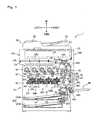
- FIG. 1 is a cross-sectional view of an internal structure of an image forming apparatus 1 according to one embodiment of the present disclosure.
- a multifunctional peripheral having a function of a printer and a copying function is illustrated as the image forming apparatus 1.
- the image forming apparatus may be a printer, a copy machine, or a facsimile apparatus.
- the image forming apparatus 1 includes an apparatus body 10 that is structured as a housing shaped in almost a rectangular parallelepiped, and an automatic document feeder 20(Document conveying apparatus) disposed on the apparatus body 10.
- a reading unit 25 an image forming portion 30, a fixing portion 60, a sheet feed portion 40, a conveying path 50, and a conveying unit 55 are accommodated.
- the reading unit 25 optically reads a document image to be copied.
- the image forming portion 30 forms a toner image on a sheet.
- the fixing portion 60 fixes the toner image onto the sheet.
- the sheet feed portion 40 stores regular sheets to be conveyed to the image forming portion 30.
- the conveying path 50 functions to convey the regular sheet from the sheet feed portion 40 or a manual sheet feed portion 46 to a sheet discharge outlet 10E through the image forming portion 30 and the fixing portion 60.
- the conveying unit 55 includes therein a sheet conveying path that is a part of the conveying path 50.
- the automatic document feeder (ADF) 20 is pivotably mounted on the top surface of the apparatus body 10.
- the ADF 20 automatically feeds a document to be copied, toward a predetermined document reading position in the apparatus body 10.
- the ADF 20 is opened upward.
- the ADF 20 includes a document tray 21 on which documents are placed, a document conveying portion 22 that conveys documents through the automatic document reading position, and a document discharge tray 23 onto which the documents having been read are discharged.
- the reading unit 25 optically reads an image on a document through a contact glass for reading of a document that is automatically fed from the ADF 20 disposed on the top surface of the apparatus body 10, or a contact glass (not shown) for reading of a document that is manually placed.
- a scanning mechanism having: a light source; a movable carriage; a reflective mirror; and the like, and an imaging device are accommodated, which is not shown.
- the imaging device performs photoelectric conversion in which the reflected light is converted to an analog electric signal.
- the analog electric signal is converted to a digital electric signal by an A/D converter circuit, and is thereafter inputted to the image forming portion 30.
- An image reading device is formed by the automatic document feeder (ADF) 20 and the reading unit 25.
- the image forming portion 30 performs a process of generating a full color toner image, and transferring the full color toner image onto a sheet.
- the image forming portion 30 includes an image forming unit 32, an intermediate transfer unit 33, and a toner supply portion 34.
- the image forming unit 32 includes four units 32Y, 32M, 32C, and 32Bk that are aligned in conjunction with each other, and that form yellow (Y), magenta (M), cyan (C), and black (Bk) toner images, respectively.
- the intermediate transfer unit 33 is disposed on and adjacent to the image forming unit 32.
- the toner supply portion 34 is disposed above the intermediate transfer unit 33.
- Each of the image forming units 32Y, 32M, 32C, and 32Bk includes a photosensitive drum 321, and includes a charging unit 322, an exposure unit 323, a developing device 324, a primary transfer roller 325, and a cleaning device 326 that are disposed around the photosensitive drum 321.
- the photosensitive drum 321 rotates about its axis, and has a circumferential surface on which an electrostatic latent image and a toner image are formed.
- a photosensitive drum formed by an amorphous-silicon (a-Si)-based material may be used as the photosensitive drum 321.
- the surface of the photosensitive drum 321 is uniformly charged by the charging unit 322.
- the exposure unit 323 includes a laser light source and optical components such as a mirror and a lens, and applies light based on image data of a document image, to the circumferential surface of the photosensitive drum 321, to form an electrostatic latent image.
- the developing device 324 supplies toner to the circumferential surface of the photosensitive drum 321 in order to develop the electrostatic latent image formed on the photosensitive drum 321.
- the developing device 324 is for a two-component developer, and includes a screw feeder, a magnetic roller, and a developing roller.
- the primary transfer roller 325 and the photosensitive drum 321 nip therebetween an intermediate transfer belt 331 provided in the intermediate transfer unit 33, to form a primary transfer nip portion, and primary transfer in which the toner image on the photosensitive drum 321 is transferred onto the intermediate transfer belt 331 is performed.
- the cleaning device 326 includes a cleaning roller or the like, and cleans the circumferential surface of the photosensitive drum 321 from which the toner image has been transferred.
- the intermediate transfer unit 33 includes the intermediate transfer belt 331, a driving roller 332, and a follower roller 333.
- the intermediate transfer belt 331 is an endless belt that extends on and between the driving roller 332 and the follower roller 333. Onto the same portion on the outer circumferential surface of the intermediate transfer belt 331, toner images are transferred from a plurality of the photosensitive drums 321, so as to be superimposed on each other (primary transfer).
- a secondary transfer roller 35 is disposed so as to face the circumferential surface of the driving roller 332.
- a nip portion formed between the driving roller 332 and the secondary transfer roller 35 acts as a secondary transfer nip portion that transfers, onto a sheet, a full color toner image obtained on the intermediate transfer belt 331 by images being superimposed on each other.
- a secondary transfer bias potential having a polarity opposite to that of the toner image is applied to one of the driving roller 332 or the secondary transfer roller 35, and the other thereof is grounded.
- the toner supply portion 34 includes a yellow-toner container 34Y, a magenta-toner container 34M, a cyan-toner container 34C, and a black-toner container 34Bk.
- the toner containers 34Y, 34C, 34M, and 34Bk store toners of respective colors, and the toners of the colors are supplied, through not-illustrated supply paths, to the developing devices 324 of the image forming units 32Y, 32M, 32C, and 32Bk corresponding to YMCBk colors, respectively.
- Each of the toner containers 34Y, 34C, 34M, and 34Bk includes a conveying screw 341 that conveys the toner in the container to a not-illustrated toner discharge outlet. The conveying screw 341 is driven to rotate by a not-illustrated driving portion, thereby supplying the toner into the developing device 324.
- the sheet feed portion 40 includes two cassettes, that is, a first sheet feed cassette 40A and a second sheet feed cassette 40B, which store regular sheets S1 among sheets on which image forming process is to be performed. These sheet feed cassettes can be drawn forward from the front of the apparatus body 10.
- the first sheet feed cassette 40A includes a sheet storage portion 41 that stores a stack of sheets formed by the regular sheets S1 being stacked, and a lifting plate 42 that lifts the stack of sheets for sheet feeding. Above the right end portion of the sheet feed cassette 40A, a pick-up roller 43, and paired rollers formed by a sheet feed roll 44 and a retard roller 45, are disposed. Due to driving of the pick-up roller 43 and the sheet feed roll 44, the sheets S1 in the uppermost layer of the stack of sheets in the sheet feed cassette 40A are fed one by one, and conveyed to the upstream end of the conveying path 50.
- the second sheet feed cassette 40B has the same structure as the first sheet feed cassette 40A.
- the manual sheet feed portion 46 (sheet feed apparatus) is disposed on a right side surface 10R of the apparatus body 10.
- the manual sheet feed portion 46 includes a manual feed tray 46A (sheet stacking portion) for manual sheet feeding, and a sheet feed roller 461.
- the manual feed tray 46A is mounted to the apparatus body 10 at the lower end portion thereof, so as to be openable and closable.
- the user opens the manual feed tray 46A as shown in the drawings, and places a sheet thereon.
- the sheet placed on the manual feed tray 46A is conveyed into a manually-fed-sheet conveying path 460 (sheet conveying path) that extends from the manual feed tray 46A, by the sheet feed roller 461 and a pair of conveying rollers 462 being driven. Further, the sheet is conveyed from the manually-fed-sheet conveying path 460 into the conveying path 50.
- the conveying path 50 includes a main conveying path 50A, a reverse conveying path 50B, a switching conveying path 50C, and a horizontal conveying path 50D.
- the main conveying path 50A conveys a sheet (regular sheet S1) from the sheet feed portion 40 through the image forming portion 30 to an exit of the fixing portion 60.
- the reverse conveying path 50B returns a sheet on which one-side printing has been performed, to the image forming portion 30, when duplex printing is to be performed on the sheet.
- the switching conveying path 50C diverts the sheet from the downstream end of the main conveying path 50A toward the upstream end of the reverse conveying path 50B.
- the horizontal conveying path 50D horizontally conveys the sheet from the downstream end of the main conveying path 50A to the sheet discharge outlet 10E disposed on a left side surface 10L of the apparatus body 10.
- a great part of the horizontal conveying path 50D is formed as a sheet conveying path accommodated in the conveying unit 55.
- a pair of registration rollers 51 is disposed, in the main conveying path 50A, upstream of the secondary transfer nip portion.
- a sheet is temporarily stopped at the pair of registration rollers 51 that is at a stop, to perform skew correction. Thereafter, the pair of registration rollers 51 is driven to rotate by a driving motor (not shown) at a predetermined time for image transfer, thereby feeding the sheet to the secondary transfer nip portion.
- a plurality of sheet conveying rollers 52 are disposed in the main conveying path 50A in order to convey sheets.
- a sheet discharge roller 53 is disposed at the end, on the downstream side, of the conveying path 50.
- the sheet discharge roller 53 feeds a sheet through the sheet discharge outlet 10E to a not-illustrated post-processing device disposed on the left side surface 10L of the apparatus body 10.
- a sheet discharge tray is provided below the sheet discharge outlet 10E.
- the conveying unit 55 is a unit that conveys, to the sheet discharge outlet 10E, a sheet conveyed from the fixing portion 60.
- the fixing portion 60 is disposed on the right side surface 10R side of the apparatus body 10
- the sheet discharge outlet 10E is disposed on the left side surface 10L side, of the apparatus body 10, which faces the right side surface 10R. Therefore, the conveying unit 55 horizontally conveys a sheet from the right side surface 10R side toward the left side surface 10L in the apparatus body 10.
- the fixing portion 60 is an induction heating type fixing device that performs a fixing process for fixing a toner image onto a sheet, and includes a heating roller 61, a fixing roller 62, a pressurizing roller 63, a fixing belt 64, and an induction heating unit 65.
- the pressurizing roller 63 is pressed against the fixing roller 62, to form a fixing nip portion.
- the heating roller 61 and the fixing belt 64 are induction-heated by the induction heating unit 65, and the heat is applied to the fixing nip portion. By the sheet passing through the fixing nip portion, a toner image having been transferred to the sheet is fixed onto the sheet.
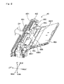
- FIG. 2 is a perspective view of the manual sheet feed portion 46 according to the present embodiment.
- FIG. 3 is an enlarged perspective view of a part of the manual sheet feed portion 46.
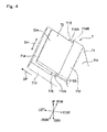
- FIG. 4 is a perspective view of a separation pad portion 7.
- the manual sheet feed portion 46 includes the manual feed tray 46A as described above, a manual feed lifting plate 46B, width regulation guides 46C, the sheet feed roller 461, and a housing 46H.
- the manual feed tray 46A is a plate-like member that is openable and closable relative to the right side surface 10R ( FIG. 1 ) of the apparatus body 10. An upper portion of the manual feed tray 46A is pivotable about a pivot portion 46A1. A plurality of sheets are stacked on the manual feed tray 46A.
- the manually-fed-sheet conveying path 460 to which a sheet is convened from the manual feed tray 46A, extends in the direction indicated by an arrow DP in FIG. 2 .
- the manual feed lifting plate 46B is a part of the top surface portion of the manual feed tray 46A, and is disposed on the left side (downstream side in the sheet conveying direction) of the manual feed tray 46A.
- the left end portion of the manual feed lifting plate 46B is movable in the up-down direction by a not-illustrated driving mechanism.
- the width regulation guides 46C are disposed on the manual feed lifting plate 46B.
- the width regulation guides 46C are disposed on the front side and the rear side, respectively, so as to be paired, and regulate a position, in the width direction, of a sheet.
- the width regulation guides 46C are movable, in the front-rear direction, along guide grooves 46B1 formed in the manual feed lifting plate 46B.
- the sheet feed roller 461 is disposed in the manually-fed-sheet conveying path 460 so as to face the manual feed tray 46A.
- the sheet feed roller 461 has a circumferential surface 461A (see FIG. 3 , FIG. 5 ) that is rotated, and conveys a sheet in the sheet conveying direction (the direction indicated by the arrow DP in FIGS. 2 and 4 ).
- the housing 46H has a box-like shape that extends in the front-rear direction.
- the housing 46H supports the sheet feed roller 461 in the center portion in the front-rear direction such that the sheet feed roller 461 is rotatable.
- a driving gear 462 is disposed in the rear end portion of the housing 46H.
- the driving gear 462 connects to the sheet feed roller 461 through a not-illustrated shaft.
- the driving gear 462 is rotated by a not-illustrated driving motor, to rotate the sheet feed roller 461 through the shaft.
- the manual sheet feed portion 46 further includes the separation pad portion 7.
- the separation pad portion 7 has a function of preventing sheets, other than an uppermost sheet, in a stack of sheets stacked on the manual feed tray 46A from being conveyed toward a nip portion N.
- the separation pad portion 7 includes a separation pad 72 (sheet feed pad) and a pad holder 71 (support member).
- the separation pad 72 is disposed so as to face the circumferential surface 461A of the sheet feed roller 461.
- the separation pad 72 includes a separation surface 72A (pad surface) that forms, between the separation surface 72A and the circumferential surface 461A, the nip portion N into which a sheet is conveyed.
- the separation pad 72 is a plate-like elastic member.
- the separation pad 72 may be formed as a rubber member.
- the separation surface 72A of the separation pad 72 has such a coefficient of friction that a friction between the separation surface 72A and a sheet is high. Due to a frictional force between a sheet and the separation surface 72A, sheets, other than an uppermost sheet, in a stack of sheets are prevented from being conveyed downstream in the sheet conveying direction.
- the pad holder 71 is disposed in the center portion, in the front-rear direction, of the housing 46H.
- the pad holder 71 supports the separation pad 72.
- the pad holder 71 has a facing surface 711, a contact surface 712, side surface portions 713, a support surface 714, and ribs 715 (rib portions).
- the facing surface 711 is a wall portion that is disposed in the right side portion of the pad holder 71 so as to extend in almost the up-down direction.
- the facing surface 711 is disposed so as to intersect the left end portion of the manual feed lifting plate 46B.
- the contact surface 712 is disposed so as to intersect the facing surface 711 in the upper end portion of the facing surface 711. When a cross-section intersecting the sheet width direction (the direction indicated by an arrow DH in FIG. 4 ) is viewed, the contact surface 712 extends so as to be inclined from the lower right side toward the upper left side. The contact surface 712 is disposed upstream of the separation pad 72 in the sheet conveying direction so as to be raised upward relative to the separation surface 72A. A leading end of a sheet fed from the manual feed tray 46A contacts with the contact surface 712.
- the side surface portions 713 are formed as a pair of side walls that forms side surfaces, in the front-rear direction, of the pad holder 71. In FIG. 3 and FIG. 4 , the side wall on the front side in the side surface portions 713 is shown.
- the support surface 714 is disposed downstream of the contact surface 712 in the sheet conveying direction, so as to be stepped from the contact surface 712. Specifically, a stepped portion 71D is formed between the contact surface 712 and the support surface 714 so as to be erected from the support surface 714 toward the contact surface 712 (see FIG. 6 ).
- the separation pad 72 is fixed. In the present embodiment, the separation pad 72 is adhered and fixed to the support surface 714. At this time, the separation pad 72 is disposed on the support surface 714 such that an upstream-side end portion 72B of the separation pad 72 faces a step surface 71D1, on the support surface 714 side, of the stepped portion 71D ( FIG. 6 ).
- the ribs 715 are disposed on both side portions, in the sheet width direction (the direction indicated by the arrow DH in FIG. 4 ), of the support surface 714 to which the separation pad 72 is fixed.
- the ribs 715 connect between the contact surface 712 and the support surface 714.
- Each rib 715 has an inclined surface 715A that extends so as to lower its front end portion from the contact surface 712 side toward the downstream side in the sheet conveying direction (the direction indicated by the arrow DP in FIG. 4 ).
- Each rib 715 (the inclined surface 715A) is disposed downward of the step surface 71D1 of the stepped portion 71D ( FIG. 6 ) in the sheet conveying direction.
- each rib 715 has a parallel surface 715B between the inclined surface 715A and the contact surface 712.
- the parallel surface 715B connects to the contact surface 712, and is coplanar with the contact surface 712.
- “extend so as to lower its front end portion in the sheet conveying direction” represents “inclined so as to deviate from the sheet conveying direction, toward the downstream side in the sheet conveying direction”. Namely, in the present embodiment, a sheet S is conveyed in the upper-left direction (in the sheet conveying direction) so as to pass through the nip portion N formed between the sheet feed roller 461 and the separation pad 72.
- the inclined surface 715A that has such a shape as to lower its front end portion toward the downstream side in the sheet conveying direction, is actually inclined by a small inclination angle and extends in the upper-left direction.
- "such a shape as to lower its front end portion" as described above represents a shape relative to the sheet conveying direction, and does not define an inclination angle of the inclined surface 715A.
- the manual sheet feed portion 46 has an urging spring 80 ( FIG. 5 ).
- the urging spring 80 is disposed between the pad holder 71 and a wall portion 101 of the apparatus body 10.
- the pad holder 71 is urged in the upper right direction by the urging spring 80.
- the separation pad 72 is pressed against the circumferential surface 461A of the sheet feed roller 461, thereby forming the nip portion N.
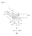
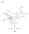
- FIG. 7 and FIG. 8 are cross-sectional views of portions near nip portions N of the manual sheet feed portion 46X and the manual sheet feed portion 46Y, respectively.
- the manual sheet feed portion 46X includes a separation pad 72X similar to the separation pad 72 of the present embodiment.
- the separation pad 72X is supported by a pad holder 71X.
- An uppermost sheet SX in a stack of sheets stacked on a not-illustrated sheet stacking portion is conveyed downstream in the sheet conveying direction (an arrow DS) according to rotation (an arrow DR) of a sheet feed roller 461X.
- the leading end of the sheet SX may enter a gap between an upstream-side end portion 72X1 of the separation pad 72X and a wall surface 71H1 of the pad holder 71X (region Z).
- the leading end portion of the sheet SX may be bent and the sheet may not be appropriately conveyed.
- the manual sheet feed portion 46Y as shown in FIG. 8 includes a film sheet 75 in addition to a separation pad 72Y and a pad holder 74.
- the film sheet 75 is a sheet member formed as a PET film.
- a lower end portion 751 of the film sheet 75 is adhered and fixed to a side surface portion 741 of the pad holder 74, to form a fixed end of the film sheet 75.
- An upper end portion 752 of the film sheet 75 forms a free end of the film sheet 75.
- the upper end portion 752 of the film sheet 75 extends so as to cover a gap between an upstream-side end portion 72Y1 of the separation pad 72Y and a wall surface 74H1 of the pad holder 74.
- the leading end of a sheet SY conveyed by a sheet feed roller 461Y is guided toward the nip portion N by the upper end portion 752 of the film sheet 75. Therefore, the leading end of the sheet SY is less likely to enter the gap between the upstream-side end portion 72Y1 of the separation pad 72Y and the wall surface 74H1 of the pad holder 74.
- the number of components of the manual sheet feed portion 46Y is increased by the film sheet 75 being disposed. As a result, cost for the manual sheet feed portion 46Y is increased. Further, in production of the manual sheet feed portion 46Y, assembling steps are increased by the film sheet 75 being adhered and fixed to the pad holder 74.
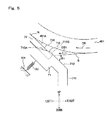
- FIG. 5 and FIG. 6 are enlarged cross-sectional views of a portion near the nip portion N of the manual sheet feed portion 46.
- an angle between the inclined surface 715A of the rib 715 and the separation surface 72A is defined as ⁇ 2, and a relationship of ⁇ 1> ⁇ 2 is satisfied.
- the leading end of the sheet S contacts with the contact surface 712 at an entering angle ⁇ 1, and thereafter contacts with the separation surface 72A at an entering angle ⁇ 2 that is less than the angle ⁇ 1. Therefore, when the sheet S contacts with the separation surface 72A, a load on the sheet S is advantageously reduced. Further, since the sheet S does not hit against the separation surface 72A at a great angle, the leading end portion of the sheet S is prevented from being bent. As a result, the sheet S is stably conveyed toward the nip portion N.
- the sheet S is conveyed toward the nip portion N in a state where the sheet S smoothly contacts with the separation surface 72A of the separation pad 72. Therefore, the film sheet 75 as provided in the manual sheet feed portion 46Y described above need not be provided in order to cause the sheet S to stably contact with the separation surface 72A. Therefore, the number of components of the manual sheet feed portion 46 is reduced, and cost for the manual sheet feed portion 46 is reduced. Further, steps of assembling the manual sheet feed portion 46 is advantageously reduced.
- the inclined surfaces 715A of the ribs 715 extend so as to connect between the contact surface 712 and the support surface 714 ( FIG. 6 ).
- each inclined surface 715A extends so as to intersect the separation surface 72A, and extends such that the inclined surface 715A has its front end portion lowered toward the downstream side in the sheet conveying direction so as to be lower than the separation surface 72A. Therefore, in a region upstream of the nip portion N in the sheet conveying direction, the downstream-side portion, in the sheet conveying direction, of the inclined surface 715A is positioned so as to be lower than the separation surface 72A. As a result, even when plural sheets S are conveyed, the sheets other than the uppermost sheet are allowed to contact with the separation surface 72A.
- the upstream-side end portion 72B on the upstream side, in the sheet conveying direction, of the separation pad 72 is disposed so as to face the step surface 71D1 of the stepped portion 71D between the contact surface 712 and the support surface 714.
- the inclined surfaces 715A are positioned downstream of the step surface 71D1 in the sheet conveying direction. Therefore, the leading end of the sheet S which contacts with the contact surface 712 is guided toward the separation surface 72A so as to move over the gap between the stepped portion 71D and the upstream-side end portion 72B of the sheet feed pad due to the ribs 715.
- the leading end of the sheet S is prevented from entering the gap between the separation pad 72 and the stepped portion 71D. Therefore, bending of the sheet S is advantageously reduced.
- the parallel surfaces 715B are disposed between the contact surface 712 and the respective inclined surfaces 715A. Therefore, the leading end of the sheet S which contacts with the contact surface 712 is guided to the separation surface 72A due to the parallel surfaces 715B without entering the gap between the stepped portion 71D and the upstream-side end portion 72B of the sheet feed pad.
- the manual sheet feed portion 46 and the image forming apparatus 1 including the manual sheet feed portion 46 according to the embodiment of the present disclosure, are described above. However, the present disclosure is not limited thereto. For example, modifications described below may be implemented.
- the manual sheet feed portion 46 is described as a sheet feed apparatus including the sheet feed roller 461 and the separation pad portion 7.
- the sheet feed apparatus may be the sheet feed portion 40 that includes the first sheet feed cassette 40A and the second sheet feed cassette 40B. Also in this case, the sheet S1 is stably fed from the first sheet feed cassette 40A or the second sheet feed cassette 40B. Further, the sheet feed apparatus may be the document conveying portion 22, in the automatic document feeder (ADF) 20, which feeds a document to a reading position.
- the image forming apparatus 1 includes an image reading apparatus described below and the image forming portion 30.
- the image reading apparatus included in the image forming apparatus 1 has: a sheet feed apparatus that has the sheet feed roller 461 and the separation pad portion 7; and the reading unit 25 (reading means) that is disposed so as to face the sheet conveying path of the sheet feed apparatus, and that reads a document image on a sheet.
- the image forming portion 30 forms an image on a sheet based on the document image read by the reading unit 25. Also in this case, a document is stably fed from the document tray 21 and an image is stably formed on a sheet.
- each rib 715 is a part of the pad holder 71.
- the ribs 715 may be support members that are separate from the pad holder 71 and that are fixed to the pad holder 71.
Landscapes
- Physics & Mathematics (AREA)
- General Physics & Mathematics (AREA)
- Engineering & Computer Science (AREA)
- Mechanical Engineering (AREA)
- Sheets, Magazines, And Separation Thereof (AREA)
Abstract
Description
- The present disclosure relates to sheet feed apparatuses that feed sheets, and document conveying apparatuses and image forming apparatuses that have the sheet feed apparatuses.
- To date, devices that feed sheets one by one from sheet stacking portions to sheet conveying paths have been known as sheet feed devices that feed sheets. The sheet feed device includes a sheet feed roller and a separation pad. The sheet feed roller is driven to rotate, thereby feeding a sheet in a sheet conveying direction. The separation pad contacts with the sheet feed roller, to form a nip portion between the separation pad and a circumferential surface of the sheet feed roller.
- A sheet enters the nip portion between the sheet feed roller and the separation pad, and is fed by rotation of the sheet feed roller. A member having a high coefficient of friction is used for the separation pad so as to prevent (simultaneous) feeding of sheets other than an uppermost sheet among the stacked sheets.
- In the conventional sheet feed device, a flexible film member having a guiding function is disposed such that, when a sheet enters the nip portion, hitting of a leading end of the sheet against the separation pad is prevented to avoid bending of the sheet. The sheet is conveyed along the film member to enter the nip portion. In this case, the number of components of the sheet feed device is increased by the film member being disposed, thereby increasing cost for the sheet feed device. Further, an operation for mounting the film member to the sheet feed device is necessary for assembling the sheet feed device.
- A sheet feed apparatus according to one aspect of the present disclosure includes a sheet stacking portion, a sheet conveying path, a sheet feed roller, a sheet feed pad, a support member, and rib portions. Sheets are stacked on the sheet stacking portion. The sheet conveying path extends from the sheet stacking portion. In the sheet conveying path, the sheet is conveyed in a predetermined conveying direction. The sheet feed roller is disposed, in the sheet conveying path, facing the sheet stacking portion. The sheet feed roller has a circumferential surface being rotated. The sheet feed roller is configured to convey the sheet. The sheet feed pad is disposed facing the circumferential surface of the sheet feed roller, and has a pad surface that forms, between the pad surface and the circumferential surface, a nip portion into which the sheet is conveyed. The support member has a support surface to which the sheet feed pad is fixed, and a contact surface located upstream of the support surface in a sheet conveying direction so as to be higher than the pad surface, and configured to make contact with a leading end of the sheet fed from the sheet stacking portion. The rib portions are disposed in the support member. The rib portions are disposed on both side portions, in a sheet width direction intersecting the sheet conveying direction, of the support surface, and the rib portions have inclined surfaces that extend so as to lower front end portions thereof, respectively, from the contact surface toward a downstream side in the sheet conveying direction.
- An image forming apparatus according to another aspect of the present disclosure includes the sheet feed apparatus and an image forming portion. The image forming portion forms an image on the sheet conveyed by the sheet feed roller.
- A document conveying apparatus according to still another aspect of the present disclosure is attached to an image reading apparatus. The document conveying apparatus conveys a document to the image reading apparatus. The document conveying apparatus includes the sheet feed apparatus.
- An image forming apparatus according to still another aspect of the present disclosure includes the document conveying apparatus and an image forming portion. The image forming portion forms an image on a sheet based on the document image read by an image reading apparatus of the image reading apparatus.
- This Summary is provided to introduce a selection of concepts in a simplified form that are further described below in the Detailed Description with reference where appropriate to the accompanying drawings. This Summary is not intended to identify key features or essential features of the claimed subject matter, nor is it intended to be used to limit the scope of the claimed subject matter. Furthermore, the claimed subject matter is not limited to implementations that solve any or all disadvantages noted in any part of this disclosure.
-
-
FIG. 1 is a cross-sectional view of an internal structure of an image forming apparatus according to an embodiment of the present disclosure. -
FIG. 2 is a perspective view of a manual sheet feed portion according to an embodiment of the present disclosure. -
FIG. 3 is an enlarged perspective view of a part of the manual sheet feed portion according to an embodiment of the present disclosure. -
FIG. 4 is a perspective view of a separation pad portion according to an embodiment of the present disclosure. -
FIG. 5 is a cross-sectional view illustrating a state where a sheet is conveyed toward a contact surface. -
FIG. 6 is a cross-sectional view illustrating a state where a sheet is conveyed toward a separation surface. -
FIG. 7 is an enlarged cross-sectional view of a part of a manual sheet feed portion as compared to the manual sheet feed portion according to one embodiment of the present disclosure. -
FIG. 8 is an enlarged cross-sectional view of a part of another manual sheet feed portion as compared to the manual sheet feed portion according to one embodiment of the present disclosure. - Hereinafter, an embodiment of the present disclosure will be described in detail with reference to the drawings.
FIG. 1 is a cross-sectional view of an internal structure of animage forming apparatus 1 according to one embodiment of the present disclosure. In the description herein, a multifunctional peripheral having a function of a printer and a copying function is illustrated as theimage forming apparatus 1. However, the image forming apparatus may be a printer, a copy machine, or a facsimile apparatus. - The
image forming apparatus 1 includes anapparatus body 10 that is structured as a housing shaped in almost a rectangular parallelepiped, and an automatic document feeder 20(Document conveying apparatus) disposed on theapparatus body 10. In theapparatus body 10, areading unit 25, animage forming portion 30, afixing portion 60, a sheet feed portion 40, aconveying path 50, and aconveying unit 55 are accommodated. Thereading unit 25 optically reads a document image to be copied. Theimage forming portion 30 forms a toner image on a sheet. Thefixing portion 60 fixes the toner image onto the sheet. The sheet feed portion 40 stores regular sheets to be conveyed to theimage forming portion 30. Theconveying path 50 functions to convey the regular sheet from the sheet feed portion 40 or a manualsheet feed portion 46 to asheet discharge outlet 10E through theimage forming portion 30 and thefixing portion 60. Theconveying unit 55 includes therein a sheet conveying path that is a part of theconveying path 50. - The automatic document feeder (ADF) 20 is pivotably mounted on the top surface of the
apparatus body 10. TheADF 20 automatically feeds a document to be copied, toward a predetermined document reading position in theapparatus body 10. On the other hand, when a user manually places a document at the predetermined document reading portion, theADF 20 is opened upward. The ADF 20 includes adocument tray 21 on which documents are placed, adocument conveying portion 22 that conveys documents through the automatic document reading position, and a document discharge tray 23 onto which the documents having been read are discharged. - The
reading unit 25 optically reads an image on a document through a contact glass for reading of a document that is automatically fed from theADF 20 disposed on the top surface of theapparatus body 10, or a contact glass (not shown) for reading of a document that is manually placed. In thereading unit 25, a scanning mechanism having: a light source; a movable carriage; a reflective mirror; and the like, and an imaging device are accommodated, which is not shown. By the scanning mechanism, light is applied to a document, and light reflected by the document is guided to the imaging device. The imaging device performs photoelectric conversion in which the reflected light is converted to an analog electric signal. The analog electric signal is converted to a digital electric signal by an A/D converter circuit, and is thereafter inputted to theimage forming portion 30. An image reading device is formed by the automatic document feeder (ADF) 20 and thereading unit 25. - The
image forming portion 30 performs a process of generating a full color toner image, and transferring the full color toner image onto a sheet. Theimage forming portion 30 includes animage forming unit 32, anintermediate transfer unit 33, and atoner supply portion 34. Theimage forming unit 32 includes fourunits intermediate transfer unit 33 is disposed on and adjacent to theimage forming unit 32. Thetoner supply portion 34 is disposed above theintermediate transfer unit 33. - Each of the
image forming units photosensitive drum 321, and includes acharging unit 322, anexposure unit 323, a developingdevice 324, aprimary transfer roller 325, and acleaning device 326 that are disposed around thephotosensitive drum 321. - The
photosensitive drum 321 rotates about its axis, and has a circumferential surface on which an electrostatic latent image and a toner image are formed. As thephotosensitive drum 321, a photosensitive drum formed by an amorphous-silicon (a-Si)-based material, may be used. The surface of thephotosensitive drum 321 is uniformly charged by the chargingunit 322. Theexposure unit 323 includes a laser light source and optical components such as a mirror and a lens, and applies light based on image data of a document image, to the circumferential surface of thephotosensitive drum 321, to form an electrostatic latent image. - The developing
device 324 supplies toner to the circumferential surface of thephotosensitive drum 321 in order to develop the electrostatic latent image formed on thephotosensitive drum 321. The developingdevice 324 is for a two-component developer, and includes a screw feeder, a magnetic roller, and a developing roller. - The
primary transfer roller 325 and thephotosensitive drum 321 nip therebetween anintermediate transfer belt 331 provided in theintermediate transfer unit 33, to form a primary transfer nip portion, and primary transfer in which the toner image on thephotosensitive drum 321 is transferred onto theintermediate transfer belt 331 is performed. Thecleaning device 326 includes a cleaning roller or the like, and cleans the circumferential surface of thephotosensitive drum 321 from which the toner image has been transferred. - The
intermediate transfer unit 33 includes theintermediate transfer belt 331, a drivingroller 332, and afollower roller 333. Theintermediate transfer belt 331 is an endless belt that extends on and between the drivingroller 332 and thefollower roller 333. Onto the same portion on the outer circumferential surface of theintermediate transfer belt 331, toner images are transferred from a plurality of thephotosensitive drums 321, so as to be superimposed on each other (primary transfer). - A
secondary transfer roller 35 is disposed so as to face the circumferential surface of the drivingroller 332. A nip portion formed between the drivingroller 332 and thesecondary transfer roller 35 acts as a secondary transfer nip portion that transfers, onto a sheet, a full color toner image obtained on theintermediate transfer belt 331 by images being superimposed on each other. A secondary transfer bias potential having a polarity opposite to that of the toner image is applied to one of the drivingroller 332 or thesecondary transfer roller 35, and the other thereof is grounded. - The
toner supply portion 34 includes a yellow-toner container 34Y, a magenta-toner container 34M, a cyan-toner container 34C, and a black-toner container 34Bk. Thetoner containers devices 324 of theimage forming units toner containers screw 341 that conveys the toner in the container to a not-illustrated toner discharge outlet. The conveyingscrew 341 is driven to rotate by a not-illustrated driving portion, thereby supplying the toner into the developingdevice 324. - The sheet feed portion 40 includes two cassettes, that is, a first
sheet feed cassette 40A and a secondsheet feed cassette 40B, which store regular sheets S1 among sheets on which image forming process is to be performed. These sheet feed cassettes can be drawn forward from the front of theapparatus body 10. - The first
sheet feed cassette 40A includes asheet storage portion 41 that stores a stack of sheets formed by the regular sheets S1 being stacked, and a liftingplate 42 that lifts the stack of sheets for sheet feeding. Above the right end portion of thesheet feed cassette 40A, a pick-uproller 43, and paired rollers formed by asheet feed roll 44 and aretard roller 45, are disposed. Due to driving of the pick-uproller 43 and thesheet feed roll 44, the sheets S1 in the uppermost layer of the stack of sheets in thesheet feed cassette 40A are fed one by one, and conveyed to the upstream end of the conveyingpath 50. The secondsheet feed cassette 40B has the same structure as the firstsheet feed cassette 40A. - On a
right side surface 10R of theapparatus body 10, the manual sheet feed portion 46 (sheet feed apparatus) is disposed. The manualsheet feed portion 46 includes amanual feed tray 46A (sheet stacking portion) for manual sheet feeding, and asheet feed roller 461. Themanual feed tray 46A is mounted to theapparatus body 10 at the lower end portion thereof, so as to be openable and closable. When manual sheet feeding is performed by a user, the user opens themanual feed tray 46A as shown in the drawings, and places a sheet thereon. The sheet placed on themanual feed tray 46A is conveyed into a manually-fed-sheet conveying path 460 (sheet conveying path) that extends from themanual feed tray 46A, by thesheet feed roller 461 and a pair of conveyingrollers 462 being driven. Further, the sheet is conveyed from the manually-fed-sheet conveying path 460 into the conveyingpath 50. - The conveying
path 50 includes a main conveyingpath 50A, areverse conveying path 50B, a switching conveying path 50C, and a horizontal conveyingpath 50D. The main conveyingpath 50A conveys a sheet (regular sheet S1) from the sheet feed portion 40 through theimage forming portion 30 to an exit of the fixingportion 60. Thereverse conveying path 50B returns a sheet on which one-side printing has been performed, to theimage forming portion 30, when duplex printing is to be performed on the sheet. The switching conveying path 50C diverts the sheet from the downstream end of the main conveyingpath 50A toward the upstream end of thereverse conveying path 50B. The horizontal conveyingpath 50D horizontally conveys the sheet from the downstream end of the main conveyingpath 50A to thesheet discharge outlet 10E disposed on aleft side surface 10L of theapparatus body 10. A great part of the horizontal conveyingpath 50D is formed as a sheet conveying path accommodated in the conveyingunit 55. - A pair of
registration rollers 51 is disposed, in the main conveyingpath 50A, upstream of the secondary transfer nip portion. A sheet is temporarily stopped at the pair ofregistration rollers 51 that is at a stop, to perform skew correction. Thereafter, the pair ofregistration rollers 51 is driven to rotate by a driving motor (not shown) at a predetermined time for image transfer, thereby feeding the sheet to the secondary transfer nip portion. In addition, a plurality ofsheet conveying rollers 52 are disposed in the main conveyingpath 50A in order to convey sheets. - A
sheet discharge roller 53 is disposed at the end, on the downstream side, of the conveyingpath 50. Thesheet discharge roller 53 feeds a sheet through thesheet discharge outlet 10E to a not-illustrated post-processing device disposed on theleft side surface 10L of theapparatus body 10. In the image forming apparatus that has no post-processing device mounted, a sheet discharge tray is provided below thesheet discharge outlet 10E. - The conveying
unit 55 is a unit that conveys, to thesheet discharge outlet 10E, a sheet conveyed from the fixingportion 60. In theimage forming apparatus 1 of the present embodiment, the fixingportion 60 is disposed on theright side surface 10R side of theapparatus body 10, and thesheet discharge outlet 10E is disposed on theleft side surface 10L side, of theapparatus body 10, which faces theright side surface 10R. Therefore, the conveyingunit 55 horizontally conveys a sheet from theright side surface 10R side toward theleft side surface 10L in theapparatus body 10. - The fixing
portion 60 is an induction heating type fixing device that performs a fixing process for fixing a toner image onto a sheet, and includes aheating roller 61, a fixingroller 62, a pressurizingroller 63, a fixingbelt 64, and aninduction heating unit 65. The pressurizingroller 63 is pressed against the fixingroller 62, to form a fixing nip portion. Theheating roller 61 and the fixingbelt 64 are induction-heated by theinduction heating unit 65, and the heat is applied to the fixing nip portion. By the sheet passing through the fixing nip portion, a toner image having been transferred to the sheet is fixed onto the sheet. - Next, the manual
sheet feed portion 46 according to the present embodiment will be described in detail with reference toFIG. 2 to FIG. 4 .FIG. 2 is a perspective view of the manualsheet feed portion 46 according to the present embodiment.FIG. 3 is an enlarged perspective view of a part of the manualsheet feed portion 46.FIG. 4 is a perspective view of aseparation pad portion 7. - As shown in
FIG. 2 , the manualsheet feed portion 46 includes themanual feed tray 46A as described above, a manualfeed lifting plate 46B, width regulation guides 46C, thesheet feed roller 461, and ahousing 46H. - The
manual feed tray 46A is a plate-like member that is openable and closable relative to theright side surface 10R (FIG. 1 ) of theapparatus body 10. An upper portion of themanual feed tray 46A is pivotable about a pivot portion 46A1. A plurality of sheets are stacked on themanual feed tray 46A. The manually-fed-sheet conveying path 460 to which a sheet is convened from themanual feed tray 46A, extends in the direction indicated by an arrow DP inFIG. 2 . - The manual
feed lifting plate 46B is a part of the top surface portion of themanual feed tray 46A, and is disposed on the left side (downstream side in the sheet conveying direction) of themanual feed tray 46A. The left end portion of the manualfeed lifting plate 46B is movable in the up-down direction by a not-illustrated driving mechanism. By the manualfeed lifting plate 46B being moved, a leading end portion (left end portion) of a stack of sheets stacked on themanual feed tray 46A is moved upward. As a result, the leading end portions of the sheets contact with thesheet feed roller 461. - The width regulation guides 46C are disposed on the manual
feed lifting plate 46B. The width regulation guides 46C are disposed on the front side and the rear side, respectively, so as to be paired, and regulate a position, in the width direction, of a sheet. The width regulation guides 46C are movable, in the front-rear direction, along guide grooves 46B1 formed in the manualfeed lifting plate 46B. - The
sheet feed roller 461 is disposed in the manually-fed-sheet conveying path 460 so as to face themanual feed tray 46A. Thesheet feed roller 461 has acircumferential surface 461A (seeFIG. 3 ,FIG. 5 ) that is rotated, and conveys a sheet in the sheet conveying direction (the direction indicated by the arrow DP inFIGS. 2 and4 ). Thehousing 46H has a box-like shape that extends in the front-rear direction. Thehousing 46H supports thesheet feed roller 461 in the center portion in the front-rear direction such that thesheet feed roller 461 is rotatable. Further, adriving gear 462 is disposed in the rear end portion of thehousing 46H. Thedriving gear 462 connects to thesheet feed roller 461 through a not-illustrated shaft. Thedriving gear 462 is rotated by a not-illustrated driving motor, to rotate thesheet feed roller 461 through the shaft. - As shown in
FIG. 3 andFIG. 4 , the manualsheet feed portion 46 further includes theseparation pad portion 7. Theseparation pad portion 7 has a function of preventing sheets, other than an uppermost sheet, in a stack of sheets stacked on themanual feed tray 46A from being conveyed toward a nip portion N. Theseparation pad portion 7 includes a separation pad 72 (sheet feed pad) and a pad holder 71 (support member). - The
separation pad 72 is disposed so as to face thecircumferential surface 461A of thesheet feed roller 461. Theseparation pad 72 includes aseparation surface 72A (pad surface) that forms, between theseparation surface 72A and thecircumferential surface 461A, the nip portion N into which a sheet is conveyed. Theseparation pad 72 is a plate-like elastic member. For example, theseparation pad 72 may be formed as a rubber member. Theseparation surface 72A of theseparation pad 72 has such a coefficient of friction that a friction between theseparation surface 72A and a sheet is high. Due to a frictional force between a sheet and theseparation surface 72A, sheets, other than an uppermost sheet, in a stack of sheets are prevented from being conveyed downstream in the sheet conveying direction. - The
pad holder 71 is disposed in the center portion, in the front-rear direction, of thehousing 46H. Thepad holder 71 supports theseparation pad 72. Thepad holder 71 has a facingsurface 711, acontact surface 712,side surface portions 713, asupport surface 714, and ribs 715 (rib portions). - The facing
surface 711 is a wall portion that is disposed in the right side portion of thepad holder 71 so as to extend in almost the up-down direction. The facingsurface 711 is disposed so as to intersect the left end portion of the manualfeed lifting plate 46B. When the manualfeed lifting plate 46B is moved in the up-down direction as described above, the head portion (the left end portion) of the manualfeed lifting plate 46B is moved in the up-down direction while facing the facingsurface 711. - The
contact surface 712 is disposed so as to intersect the facingsurface 711 in the upper end portion of the facingsurface 711. When a cross-section intersecting the sheet width direction (the direction indicated by an arrow DH inFIG. 4 ) is viewed, thecontact surface 712 extends so as to be inclined from the lower right side toward the upper left side. Thecontact surface 712 is disposed upstream of theseparation pad 72 in the sheet conveying direction so as to be raised upward relative to theseparation surface 72A. A leading end of a sheet fed from themanual feed tray 46A contacts with thecontact surface 712. - The
side surface portions 713 are formed as a pair of side walls that forms side surfaces, in the front-rear direction, of thepad holder 71. InFIG. 3 andFIG. 4 , the side wall on the front side in theside surface portions 713 is shown. - The
support surface 714 is disposed downstream of thecontact surface 712 in the sheet conveying direction, so as to be stepped from thecontact surface 712. Specifically, a steppedportion 71D is formed between thecontact surface 712 and thesupport surface 714 so as to be erected from thesupport surface 714 toward the contact surface 712 (seeFIG. 6 ). To thesupport surface 714, theseparation pad 72 is fixed. In the present embodiment, theseparation pad 72 is adhered and fixed to thesupport surface 714. At this time, theseparation pad 72 is disposed on thesupport surface 714 such that an upstream-side end portion 72B of theseparation pad 72 faces a step surface 71D1, on thesupport surface 714 side, of the steppedportion 71D (FIG. 6 ). - The
ribs 715 are disposed on both side portions, in the sheet width direction (the direction indicated by the arrow DH inFIG. 4 ), of thesupport surface 714 to which theseparation pad 72 is fixed. Theribs 715 connect between thecontact surface 712 and thesupport surface 714. Eachrib 715 has aninclined surface 715A that extends so as to lower its front end portion from thecontact surface 712 side toward the downstream side in the sheet conveying direction (the direction indicated by the arrow DP inFIG. 4 ). Each rib 715 (theinclined surface 715A) is disposed downward of the step surface 71D1 of the steppedportion 71D (FIG. 6 ) in the sheet conveying direction. Further, eachrib 715 has aparallel surface 715B between theinclined surface 715A and thecontact surface 712. Theparallel surface 715B connects to thecontact surface 712, and is coplanar with thecontact surface 712. In the below description, "extend so as to lower its front end portion in the sheet conveying direction" represents "inclined so as to deviate from the sheet conveying direction, toward the downstream side in the sheet conveying direction". Namely, in the present embodiment, a sheet S is conveyed in the upper-left direction (in the sheet conveying direction) so as to pass through the nip portion N formed between thesheet feed roller 461 and theseparation pad 72. Therefore, theinclined surface 715A that has such a shape as to lower its front end portion toward the downstream side in the sheet conveying direction, is actually inclined by a small inclination angle and extends in the upper-left direction. In other words, "such a shape as to lower its front end portion" as described above represents a shape relative to the sheet conveying direction, and does not define an inclination angle of theinclined surface 715A. - Further, the manual
sheet feed portion 46 has an urging spring 80 (FIG. 5 ). - The urging
spring 80 is disposed between thepad holder 71 and awall portion 101 of theapparatus body 10. Thepad holder 71 is urged in the upper right direction by the urgingspring 80. As a result, theseparation pad 72 is pressed against thecircumferential surface 461A of thesheet feed roller 461, thereby forming the nip portion N. - In
FIG. 3 , when the manualfeed lifting plate 46B is moved upward as indicated by an arrow DB, an uppermost sheet in a stack of sheets stacked on themanual feed tray 46A contacts with thecircumferential surface 461A of thesheet feed roller 461. When thesheet feed roller 461 is rotated in the direction indicated by an arrow DR, the sheet is conveyed toward the nip portion N (FIG. 5 ) between thesheet feed roller 461 and theseparation pad 72. - Next, problems with a manual
sheet feed portion 46X and a manualsheet feed portion 46Y as compared to the manualsheet feed portion 46 of the present embodiment, will be described.FIG. 7 andFIG. 8 are cross-sectional views of portions near nip portions N of the manualsheet feed portion 46X and the manualsheet feed portion 46Y, respectively. - As shown in
FIG. 7 , the manualsheet feed portion 46X includes aseparation pad 72X similar to theseparation pad 72 of the present embodiment. Theseparation pad 72X is supported by apad holder 71X. An uppermost sheet SX in a stack of sheets stacked on a not-illustrated sheet stacking portion is conveyed downstream in the sheet conveying direction (an arrow DS) according to rotation (an arrow DR) of asheet feed roller 461X. At this time, the leading end of the sheet SX may enter a gap between an upstream-side end portion 72X1 of theseparation pad 72X and a wall surface 71H1 of thepad holder 71X (region Z). As a result, the leading end portion of the sheet SX may be bent and the sheet may not be appropriately conveyed. - On the other hand, the manual
sheet feed portion 46Y as shown inFIG. 8 includes afilm sheet 75 in addition to aseparation pad 72Y and apad holder 74. Thefilm sheet 75 is a sheet member formed as a PET film. Alower end portion 751 of thefilm sheet 75 is adhered and fixed to aside surface portion 741 of thepad holder 74, to form a fixed end of thefilm sheet 75. Anupper end portion 752 of thefilm sheet 75 forms a free end of thefilm sheet 75. Theupper end portion 752 of thefilm sheet 75 extends so as to cover a gap between an upstream-side end portion 72Y1 of theseparation pad 72Y and a wall surface 74H1 of thepad holder 74. In the manualsheet feed portion 46Y having such a structure, the leading end of a sheet SY conveyed by asheet feed roller 461Y is guided toward the nip portion N by theupper end portion 752 of thefilm sheet 75. Therefore, the leading end of the sheet SY is less likely to enter the gap between the upstream-side end portion 72Y1 of theseparation pad 72Y and the wall surface 74H1 of thepad holder 74. - However, in the manual
sheet feed portion 46Y as described above, the number of components of the manualsheet feed portion 46Y is increased by thefilm sheet 75 being disposed. As a result, cost for the manualsheet feed portion 46Y is increased. Further, in production of the manualsheet feed portion 46Y, assembling steps are increased by thefilm sheet 75 being adhered and fixed to thepad holder 74. - In order to solve the aforementioned problems, in the manual
sheet feed portion 46 of the present embodiment, theribs 715 are used to stably convey a sheet toward the nip portion N. Next, an action of the manualsheet feed portion 46 of the present embodiment will be described with reference toFIG. 5 andFIG. 6 .FIG. 5 andFIG. 6 are enlarged cross-sectional views of a portion near the nip portion N of the manualsheet feed portion 46. - As described above, when the manual
feed lifting plate 46B (FIG. 3 ) is moved upward, and thesheet feed roller 461 is rotated (the arrow DR inFIG. 5 ), the sheet S is conveyed in the direction indicated by an arrow DS1. At this time, due to frictional force among sheets, several sheets S may be conveyed in the direction indicated by the arrow DS1. The leading end of the sheet S conveyed by thesheet feed roller 461 contacts with thecontact surface 712 of thepad holder 71 as shown inFIG. 5 . At this time, an angle between the leading end of the sheet S and thecontact surface 712 is defined as θ1. The sheet S (sheet S(1) inFIG. 6 ) that contacts with thecontact surface 712, is conveyed toward the nip portion N while frictionally sliding on thecontact surface 712 due to rotational force of the sheet feed roller 461 (sheet S(2) inFIG. 6 ). Thereafter, the sheet S is conveyed toward theseparation surface 72A along theinclined surfaces 715A of the ribs 715 (an arrow DS2 inFIG. 6 ). In the present embodiment, an angle between theinclined surface 715A of therib 715 and theseparation surface 72A is defined as θ2, and a relationship of θ1>θ2 is satisfied. Therefore, the leading end of the sheet S contacts with thecontact surface 712 at an entering angle θ1, and thereafter contacts with theseparation surface 72A at an entering angle θ2 that is less than the angle θ1. Therefore, when the sheet S contacts with theseparation surface 72A, a load on the sheet S is advantageously reduced. Further, since the sheet S does not hit against theseparation surface 72A at a great angle, the leading end portion of the sheet S is prevented from being bent. As a result, the sheet S is stably conveyed toward the nip portion N. - In the present embodiment, as described above, since the
ribs 715 are disposed on both side portions of theseparation pad 72, the sheet S is conveyed toward the nip portion N in a state where the sheet S smoothly contacts with theseparation surface 72A of theseparation pad 72. Therefore, thefilm sheet 75 as provided in the manualsheet feed portion 46Y described above need not be provided in order to cause the sheet S to stably contact with theseparation surface 72A. Therefore, the number of components of the manualsheet feed portion 46 is reduced, and cost for the manualsheet feed portion 46 is reduced. Further, steps of assembling the manualsheet feed portion 46 is advantageously reduced. - Even in a case where plural sheets S are conveyed toward the
separation pad 72 due to rotational force of thesheet feed roller 461 and frictional force among the sheets S as described above, only an uppermost sheet S (the sheet closest to the sheet feed roller 461) is conveyed toward the nip portion N by thesheet feed roller 461 due to frictional force between the sheet S and theseparation surface 72A. In other words, brake is applied to the sheets S other than the uppermost sheet due to frictional force between the sheets and theseparation surface 72A. - Further, in the present embodiment, the
inclined surfaces 715A of theribs 715 extend so as to connect between thecontact surface 712 and the support surface 714 (FIG. 6 ). In other words, when a cross-section intersecting the sheet width direction is viewed, eachinclined surface 715A extends so as to intersect theseparation surface 72A, and extends such that theinclined surface 715A has its front end portion lowered toward the downstream side in the sheet conveying direction so as to be lower than theseparation surface 72A. Therefore, in a region upstream of the nip portion N in the sheet conveying direction, the downstream-side portion, in the sheet conveying direction, of theinclined surface 715A is positioned so as to be lower than theseparation surface 72A. As a result, even when plural sheets S are conveyed, the sheets other than the uppermost sheet are allowed to contact with theseparation surface 72A. - Further, in the present embodiment, as shown in
FIG. 6 , the upstream-side end portion 72B on the upstream side, in the sheet conveying direction, of theseparation pad 72 is disposed so as to face the step surface 71D1 of the steppedportion 71D between thecontact surface 712 and thesupport surface 714. Theinclined surfaces 715A are positioned downstream of the step surface 71D1 in the sheet conveying direction. Therefore, the leading end of the sheet S which contacts with thecontact surface 712 is guided toward theseparation surface 72A so as to move over the gap between the steppedportion 71D and the upstream-side end portion 72B of the sheet feed pad due to theribs 715. As a result, the leading end of the sheet S is prevented from entering the gap between theseparation pad 72 and the steppedportion 71D. Therefore, bending of the sheet S is advantageously reduced. Further, theparallel surfaces 715B are disposed between thecontact surface 712 and the respectiveinclined surfaces 715A. Therefore, the leading end of the sheet S which contacts with thecontact surface 712 is guided to theseparation surface 72A due to theparallel surfaces 715B without entering the gap between the steppedportion 71D and the upstream-side end portion 72B of the sheet feed pad. - The manual
sheet feed portion 46 and theimage forming apparatus 1 including the manualsheet feed portion 46 according to the embodiment of the present disclosure, are described above. However, the present disclosure is not limited thereto. For example, modifications described below may be implemented. - In the above embodiment, the manual
sheet feed portion 46 is described as a sheet feed apparatus including thesheet feed roller 461 and theseparation pad portion 7. However, the present disclosure is not limited thereto. The sheet feed apparatus may be the sheet feed portion 40 that includes the firstsheet feed cassette 40A and the secondsheet feed cassette 40B. Also in this case, the sheet S1 is stably fed from the firstsheet feed cassette 40A or the secondsheet feed cassette 40B. Further, the sheet feed apparatus may be thedocument conveying portion 22, in the automatic document feeder (ADF) 20, which feeds a document to a reading position. In this case, theimage forming apparatus 1 includes an image reading apparatus described below and theimage forming portion 30. The image reading apparatus included in theimage forming apparatus 1 has: a sheet feed apparatus that has thesheet feed roller 461 and theseparation pad portion 7; and the reading unit 25 (reading means) that is disposed so as to face the sheet conveying path of the sheet feed apparatus, and that reads a document image on a sheet. Theimage forming portion 30 forms an image on a sheet based on the document image read by thereading unit 25. Also in this case, a document is stably fed from thedocument tray 21 and an image is stably formed on a sheet. - In the embodiment described above, each
rib 715 is a part of thepad holder 71. However, the present disclosure is not limited thereto. Theribs 715 may be support members that are separate from thepad holder 71 and that are fixed to thepad holder 71. - It is to be understood that the embodiments herein are illustrative and not restrictive, since the scope of the invention is defined by the appended claims rather than by the description preceding them, and all changes that fall within metes and bounds of the claims, or equivalence of such metes and bounds thereof are therefore intended to be embraced by the claims.
Claims (9)
- A sheet feed apparatus (46) comprising:a sheet stacking portion (46A) on which sheets are stacked;a sheet conveying path (460), extending from the sheet stacking portion (46A), in which the sheet is conveyed in a predetermined conveying direction;a sheet feed roller (461) disposed, in the sheet conveying path (460), facing the sheet stacking portion (46A), and having a circumferential surface being rotated, the sheet feed roller configured to convey the sheet;a sheet feed pad (72) disposed facing the circumferential surface of the sheet feed roller (461), and having a pad surface that forms, between the pad surface and the circumferential surface, a nip portion into which the sheet is conveyed;a support member (71) having a support surface (714) to which the sheet feed pad (72) is fixed, and a contact surface (712) located upstream of the support surface (714) in a sheet conveying direction so as to be higher than the pad surface, and configured to make contact with a leading end of the sheet fed from the sheet stacking portion (46A); andrib portions (715) disposed in the support member (71) on both side portions, in a sheet width direction intersecting the sheet conveying direction, of the support surface (714), the rib portions having inclined surfaces (715A) that extend so as to lower front end portions thereof, respectively, from the contact surface (712) toward a downstream side in the sheet conveying direction.
- The sheet feed apparatus (46) according to claim 1, wherein, in a case where a cross-section intersecting the sheet width direction is viewed, when θ1 represents an angle that is formed between a leading end of the sheet and the contact surface (712) when the sheet contacts with the contact surface (712), and θ2 represents an angle between the pad surface and each inclined surface (715A) of each rib portion (715), a relationship of θ1>θ2 is satisfied.
- The sheet feed apparatus (46) according to claim 1 or 2, wherein, in a case where the cross-section intersecting the sheet width direction is viewed, the inclined surfaces (715A) extend so as to intersect the pad surface, and extend so as to lower the front end portions toward the downstream side in the sheet conveying direction such that the front end portions of the inclined surfaces (715A) are lower than the pad surface.
- The sheet feed apparatus (46) according to one of claims 1 to 3, wherein
the support member (71) has a stepped portion (71D) that is erected from the support surface (714) toward the contact surface (712),
an end portion (72B) on an upstream side, in the sheet conveying direction, of the sheet feed pad (72) is positioned on the support surface (714) side so as to face a step surface (71D1) of the stepped portion (71D), and
the rib portions (715) are disposed downstream of the step surface (71D1) in the sheet conveying direction. - The sheet feed apparatus (46) according to one of claims 1 to 4, wherein the rib portions (715) have parallel surfaces (715B) that are disposed, between the respective inclined surfaces (715A) and the contact surface (712), so as to connect between the contact surface (712) and the respective incline surfaces, and be parallel to the contact surface (712).
- An image forming apparatus comprising:the sheet feed apparatus (46) according to one of claims 1 to 5; andan image forming portion (30) that forms an image on the sheet conveyed by the sheet feed roller (461).
- The image forming apparatus according to claim 6, wherein the sheet stacking portion (46A) is a manual feed tray.
- A document conveying apparatus attached to an image reading apparatus (25) and conveying a document to the image reading apparatus (25), the document conveying apparatus comprising the sheet feed apparatus (46) according to one of claims 1 to 5.
- An image forming apparatus comprising:the document conveying apparatus according to claim 8; andan image forming portion (30) that forms an image on a sheet based on the document image read by the image reading apparatus (25).
Applications Claiming Priority (1)
| Application Number | Priority Date | Filing Date | Title |
|---|---|---|---|
| JP2012253278A JP5771590B2 (en) | 2012-11-19 | 2012-11-19 | Paper feeding device, and image reading device and image forming apparatus provided with the same |
Publications (3)
| Publication Number | Publication Date |
|---|---|
| EP2733541A2 true EP2733541A2 (en) | 2014-05-21 |
| EP2733541A3 EP2733541A3 (en) | 2017-08-16 |
| EP2733541B1 EP2733541B1 (en) | 2019-08-14 |
Family
ID=49582614
Family Applications (1)
| Application Number | Title | Priority Date | Filing Date |
|---|---|---|---|
| EP13192741.0A Active EP2733541B1 (en) | 2012-11-19 | 2013-11-13 | Sheet feed apparatus, and document conveying apparatus and image forming apparatus having the same |
Country Status (4)
| Country | Link |
|---|---|
| US (1) | US8876104B2 (en) |
| EP (1) | EP2733541B1 (en) |
| JP (1) | JP5771590B2 (en) |
| CN (2) | CN103818742B (en) |
Families Citing this family (6)
| Publication number | Priority date | Publication date | Assignee | Title |
|---|---|---|---|---|
| JP6440086B2 (en) * | 2014-03-17 | 2018-12-19 | 株式会社リコー | Sheet feeding apparatus and image forming apparatus |
| JP2015196570A (en) * | 2014-04-01 | 2015-11-09 | 株式会社リコー | Sheet feeding device, image formation device, and image reader |
| JP6589332B2 (en) * | 2015-03-27 | 2019-10-16 | 富士ゼロックス株式会社 | Medium conveying apparatus and image forming apparatus |
| CN111586248B (en) * | 2019-02-19 | 2022-08-02 | 柯尼卡美能达办公系统研发(无锡)有限公司 | Image reading apparatus and image forming apparatus |
| JP2022029072A (en) * | 2020-08-04 | 2022-02-17 | 京セラドキュメントソリューションズ株式会社 | Sorting device |
| JP7665126B2 (en) * | 2020-11-05 | 2025-04-21 | ブラザー工業株式会社 | Image Processing Device |
Family Cites Families (14)
| Publication number | Priority date | Publication date | Assignee | Title |
|---|---|---|---|---|
| JPS59105234U (en) * | 1982-12-29 | 1984-07-16 | カシオ計算機株式会社 | Paper feed separation device |
| JPH0289737A (en) | 1988-09-27 | 1990-03-29 | Mita Ind Co Ltd | Roller-type paper feeding device |
| US5163668A (en) * | 1991-08-29 | 1992-11-17 | Xerox Corporation | Retard pad assembly with movable compliant entrance guide |
| JP3731709B2 (en) * | 1998-08-20 | 2006-01-05 | 株式会社リコー | Separating paper feeder |
| JP2003252468A (en) * | 2002-03-06 | 2003-09-10 | Sharp Corp | Paper feeder and image forming apparatus |
| US7152859B2 (en) * | 2004-06-15 | 2006-12-26 | Xerox Corporation | Sheet separator |
| CN100372749C (en) * | 2005-04-15 | 2008-03-05 | 虹光精密工业(苏州)有限公司 | Paper Separation Mechanism for Image Input/Output Devices |
| JP4840977B2 (en) * | 2006-04-27 | 2011-12-21 | 京セラミタ株式会社 | Sheet feeding apparatus, and image reading apparatus and image forming apparatus provided with the same |
| JP2008127118A (en) * | 2006-11-16 | 2008-06-05 | Canon Inc | Sheet feeding apparatus and image forming apparatus |
| JP2008308314A (en) * | 2007-06-18 | 2008-12-25 | Canon Inc | Sheet feeding apparatus, image forming apparatus, and image reading apparatus |
| CN101734498B (en) * | 2008-11-26 | 2012-03-28 | 东友科技股份有限公司 | Paper separation device with noise suppression function, automatic paper feeding device and adjustment method |
| JP5103492B2 (en) * | 2010-02-24 | 2012-12-19 | 京セラドキュメントソリューションズ株式会社 | Image forming apparatus |
| JP5534984B2 (en) * | 2010-07-01 | 2014-07-02 | キヤノン株式会社 | Image forming apparatus, paper feed control method, and program |
| US8651476B2 (en) * | 2012-05-29 | 2014-02-18 | Hewlett-Packard Development Company, L.P. | Separator assembly |
-
2012
- 2012-11-19 JP JP2012253278A patent/JP5771590B2/en active Active
-
2013
- 2013-11-11 US US14/077,107 patent/US8876104B2/en active Active
- 2013-11-12 CN CN201310559807.4A patent/CN103818742B/en active Active
- 2013-11-12 CN CN201610388627.8A patent/CN106019884B/en active Active
- 2013-11-13 EP EP13192741.0A patent/EP2733541B1/en active Active
Non-Patent Citations (1)
| Title |
|---|
| None |
Also Published As
| Publication number | Publication date |
|---|---|
| JP5771590B2 (en) | 2015-09-02 |
| US8876104B2 (en) | 2014-11-04 |
| US20140138903A1 (en) | 2014-05-22 |
| CN103818742A (en) | 2014-05-28 |
| CN106019884A (en) | 2016-10-12 |
| EP2733541A3 (en) | 2017-08-16 |
| CN103818742B (en) | 2016-08-17 |
| JP2014101178A (en) | 2014-06-05 |
| EP2733541B1 (en) | 2019-08-14 |
| CN106019884B (en) | 2018-07-06 |
Similar Documents
| Publication | Publication Date | Title |
|---|---|---|
| US8517373B2 (en) | Sheet feeder with pickup roller and image forming apparatus | |
| JP5135371B2 (en) | Image forming apparatus and relay unit | |
| EP2733541B1 (en) | Sheet feed apparatus, and document conveying apparatus and image forming apparatus having the same | |
| US8528895B2 (en) | Sheet feeder and image forming apparatus with the same | |
| KR101512357B1 (en) | Sheet transport apparatus, image reading apparatus including the same and image forming apparatus | |
| US9170548B2 (en) | Sheet discharge device, and image forming apparatus provided with the same | |
| US8840110B2 (en) | Sheet conveying device, image reading device provided with the same, and image forming apparatus provided with the same | |
| EP1276310A2 (en) | Original feeding apparatus, original reading apparatus, and image forming apparatus | |
| CN100554107C (en) | Paper feeding device and image forming apparatus including the same | |
| US20130321882A1 (en) | Image reading apparatus and image forming apparatus provided with same | |
| JP2012194331A (en) | Fixing device and image forming apparatus | |
| US8913309B2 (en) | Image reading apparatus and image forming apparatus | |
| CN103728857A (en) | Image forming apparatus | |
| JP5588922B2 (en) | Conveying mechanism and image forming apparatus having the same | |
| JP5591572B2 (en) | Medium conveying apparatus and image forming apparatus | |
| JP5961729B2 (en) | Paper feeding device, and image reading device and image forming apparatus provided with the same | |
| US8104760B2 (en) | Automatic document transport device, image reading device, and image forming apparatus | |
| JP2011201640A (en) | Image forming device | |
| JP2009234706A (en) | Paper feeding device and image forming device using the same | |
| JP5498845B2 (en) | Attachment mechanism, sheet supply unit, and image forming apparatus | |
| JP2019089610A (en) | Sheet discharge apparatus and image reading apparatus | |
| JP6518495B2 (en) | Sheet feeding apparatus and image forming apparatus provided with the same | |
| JP6685679B2 (en) | Sheet feeding apparatus and image forming apparatus | |
| JP5509115B2 (en) | Image forming apparatus | |
| JP2011195240A (en) | Carrying unit and image forming device equipped therewith |
Legal Events
| Date | Code | Title | Description |
|---|---|---|---|
| PUAI | Public reference made under article 153(3) epc to a published international application that has entered the european phase |
Free format text: ORIGINAL CODE: 0009012 |
|
| 17P | Request for examination filed |
Effective date: 20131113 |
|
| AK | Designated contracting states |
Kind code of ref document: A2 Designated state(s): AL AT BE BG CH CY CZ DE DK EE ES FI FR GB GR HR HU IE IS IT LI LT LU LV MC MK MT NL NO PL PT RO RS SE SI SK SM TR |
|
| AX | Request for extension of the european patent |
Extension state: BA ME |
|
| PUAL | Search report despatched |
Free format text: ORIGINAL CODE: 0009013 |
|
| AK | Designated contracting states |
Kind code of ref document: A3 Designated state(s): AL AT BE BG CH CY CZ DE DK EE ES FI FR GB GR HR HU IE IS IT LI LT LU LV MC MK MT NL NO PL PT RO RS SE SI SK SM TR |
|
| AX | Request for extension of the european patent |
Extension state: BA ME |
|
| RIC1 | Information provided on ipc code assigned before grant |
Ipc: G03G 15/00 20060101AFI20170707BHEP Ipc: B65H 5/06 20060101ALI20170707BHEP Ipc: B65H 3/52 20060101ALI20170707BHEP |
|
| STAA | Information on the status of an ep patent application or granted ep patent |
Free format text: STATUS: REQUEST FOR EXAMINATION WAS MADE |
|
| R17P | Request for examination filed (corrected) |
Effective date: 20180206 |
|
| RBV | Designated contracting states (corrected) |
Designated state(s): AL AT BE BG CH CY CZ DE DK EE ES FI FR GB GR HR HU IE IS IT LI LT LU LV MC MK MT NL NO PL PT RO RS SE SI SK SM TR |
|
| RIC1 | Information provided on ipc code assigned before grant |
Ipc: G03G 15/00 20060101AFI20190208BHEP Ipc: B65H 3/52 20060101ALI20190208BHEP Ipc: B65H 5/06 20060101ALI20190208BHEP |
|
| GRAP | Despatch of communication of intention to grant a patent |
Free format text: ORIGINAL CODE: EPIDOSNIGR1 |
|
| STAA | Information on the status of an ep patent application or granted ep patent |
Free format text: STATUS: GRANT OF PATENT IS INTENDED |
|
| INTG | Intention to grant announced |
Effective date: 20190327 |
|
| GRAS | Grant fee paid |
Free format text: ORIGINAL CODE: EPIDOSNIGR3 |
|
| GRAA | (expected) grant |
Free format text: ORIGINAL CODE: 0009210 |
|
| STAA | Information on the status of an ep patent application or granted ep patent |
Free format text: STATUS: THE PATENT HAS BEEN GRANTED |
|
| AK | Designated contracting states |
Kind code of ref document: B1 Designated state(s): AL AT BE BG CH CY CZ DE DK EE ES FI FR GB GR HR HU IE IS IT LI LT LU LV MC MK MT NL NO PL PT RO RS SE SI SK SM TR |
|
| REG | Reference to a national code |
Ref country code: GB Ref legal event code: FG4D |
|
| REG | Reference to a national code |
Ref country code: CH Ref legal event code: EP Ref country code: AT Ref legal event code: REF Ref document number: 1167740 Country of ref document: AT Kind code of ref document: T Effective date: 20190815 |
|
| REG | Reference to a national code |
Ref country code: DE Ref legal event code: R096 Ref document number: 602013059083 Country of ref document: DE |
|
| REG | Reference to a national code |
Ref country code: IE Ref legal event code: FG4D |
|
| REG | Reference to a national code |
Ref country code: NL Ref legal event code: MP Effective date: 20190814 |
|
| REG | Reference to a national code |
Ref country code: LT Ref legal event code: MG4D |
|
| PG25 | Lapsed in a contracting state [announced via postgrant information from national office to epo] |
Ref country code: BG Free format text: LAPSE BECAUSE OF FAILURE TO SUBMIT A TRANSLATION OF THE DESCRIPTION OR TO PAY THE FEE WITHIN THE PRESCRIBED TIME-LIMIT Effective date: 20191114 Ref country code: NO Free format text: LAPSE BECAUSE OF FAILURE TO SUBMIT A TRANSLATION OF THE DESCRIPTION OR TO PAY THE FEE WITHIN THE PRESCRIBED TIME-LIMIT Effective date: 20191114 Ref country code: LT Free format text: LAPSE BECAUSE OF FAILURE TO SUBMIT A TRANSLATION OF THE DESCRIPTION OR TO PAY THE FEE WITHIN THE PRESCRIBED TIME-LIMIT Effective date: 20190814 Ref country code: FI Free format text: LAPSE BECAUSE OF FAILURE TO SUBMIT A TRANSLATION OF THE DESCRIPTION OR TO PAY THE FEE WITHIN THE PRESCRIBED TIME-LIMIT Effective date: 20190814 Ref country code: NL Free format text: LAPSE BECAUSE OF FAILURE TO SUBMIT A TRANSLATION OF THE DESCRIPTION OR TO PAY THE FEE WITHIN THE PRESCRIBED TIME-LIMIT Effective date: 20190814 Ref country code: SE Free format text: LAPSE BECAUSE OF FAILURE TO SUBMIT A TRANSLATION OF THE DESCRIPTION OR TO PAY THE FEE WITHIN THE PRESCRIBED TIME-LIMIT Effective date: 20190814 Ref country code: HR Free format text: LAPSE BECAUSE OF FAILURE TO SUBMIT A TRANSLATION OF THE DESCRIPTION OR TO PAY THE FEE WITHIN THE PRESCRIBED TIME-LIMIT Effective date: 20190814 Ref country code: PT Free format text: LAPSE BECAUSE OF FAILURE TO SUBMIT A TRANSLATION OF THE DESCRIPTION OR TO PAY THE FEE WITHIN THE PRESCRIBED TIME-LIMIT Effective date: 20191216 |
|
| REG | Reference to a national code |
Ref country code: AT Ref legal event code: MK05 Ref document number: 1167740 Country of ref document: AT Kind code of ref document: T Effective date: 20190814 |
|
| PG25 | Lapsed in a contracting state [announced via postgrant information from national office to epo] |
Ref country code: AL Free format text: LAPSE BECAUSE OF FAILURE TO SUBMIT A TRANSLATION OF THE DESCRIPTION OR TO PAY THE FEE WITHIN THE PRESCRIBED TIME-LIMIT Effective date: 20190814 Ref country code: LV Free format text: LAPSE BECAUSE OF FAILURE TO SUBMIT A TRANSLATION OF THE DESCRIPTION OR TO PAY THE FEE WITHIN THE PRESCRIBED TIME-LIMIT Effective date: 20190814 Ref country code: GR Free format text: LAPSE BECAUSE OF FAILURE TO SUBMIT A TRANSLATION OF THE DESCRIPTION OR TO PAY THE FEE WITHIN THE PRESCRIBED TIME-LIMIT Effective date: 20191115 Ref country code: RS Free format text: LAPSE BECAUSE OF FAILURE TO SUBMIT A TRANSLATION OF THE DESCRIPTION OR TO PAY THE FEE WITHIN THE PRESCRIBED TIME-LIMIT Effective date: 20190814 Ref country code: IS Free format text: LAPSE BECAUSE OF FAILURE TO SUBMIT A TRANSLATION OF THE DESCRIPTION OR TO PAY THE FEE WITHIN THE PRESCRIBED TIME-LIMIT Effective date: 20191214 Ref country code: ES Free format text: LAPSE BECAUSE OF FAILURE TO SUBMIT A TRANSLATION OF THE DESCRIPTION OR TO PAY THE FEE WITHIN THE PRESCRIBED TIME-LIMIT Effective date: 20190814 |
|
| PG25 | Lapsed in a contracting state [announced via postgrant information from national office to epo] |
Ref country code: TR Free format text: LAPSE BECAUSE OF FAILURE TO SUBMIT A TRANSLATION OF THE DESCRIPTION OR TO PAY THE FEE WITHIN THE PRESCRIBED TIME-LIMIT Effective date: 20190814 |
|
| PG25 | Lapsed in a contracting state [announced via postgrant information from national office to epo] |
Ref country code: IT Free format text: LAPSE BECAUSE OF FAILURE TO SUBMIT A TRANSLATION OF THE DESCRIPTION OR TO PAY THE FEE WITHIN THE PRESCRIBED TIME-LIMIT Effective date: 20190814 Ref country code: DK Free format text: LAPSE BECAUSE OF FAILURE TO SUBMIT A TRANSLATION OF THE DESCRIPTION OR TO PAY THE FEE WITHIN THE PRESCRIBED TIME-LIMIT Effective date: 20190814 Ref country code: AT Free format text: LAPSE BECAUSE OF FAILURE TO SUBMIT A TRANSLATION OF THE DESCRIPTION OR TO PAY THE FEE WITHIN THE PRESCRIBED TIME-LIMIT Effective date: 20190814 Ref country code: EE Free format text: LAPSE BECAUSE OF FAILURE TO SUBMIT A TRANSLATION OF THE DESCRIPTION OR TO PAY THE FEE WITHIN THE PRESCRIBED TIME-LIMIT Effective date: 20190814 Ref country code: PL Free format text: LAPSE BECAUSE OF FAILURE TO SUBMIT A TRANSLATION OF THE DESCRIPTION OR TO PAY THE FEE WITHIN THE PRESCRIBED TIME-LIMIT Effective date: 20190814 Ref country code: RO Free format text: LAPSE BECAUSE OF FAILURE TO SUBMIT A TRANSLATION OF THE DESCRIPTION OR TO PAY THE FEE WITHIN THE PRESCRIBED TIME-LIMIT Effective date: 20190814 |
|
| PG25 | Lapsed in a contracting state [announced via postgrant information from national office to epo] |
Ref country code: CZ Free format text: LAPSE BECAUSE OF FAILURE TO SUBMIT A TRANSLATION OF THE DESCRIPTION OR TO PAY THE FEE WITHIN THE PRESCRIBED TIME-LIMIT Effective date: 20190814 Ref country code: SM Free format text: LAPSE BECAUSE OF FAILURE TO SUBMIT A TRANSLATION OF THE DESCRIPTION OR TO PAY THE FEE WITHIN THE PRESCRIBED TIME-LIMIT Effective date: 20190814 Ref country code: IS Free format text: LAPSE BECAUSE OF FAILURE TO SUBMIT A TRANSLATION OF THE DESCRIPTION OR TO PAY THE FEE WITHIN THE PRESCRIBED TIME-LIMIT Effective date: 20200224 Ref country code: SK Free format text: LAPSE BECAUSE OF FAILURE TO SUBMIT A TRANSLATION OF THE DESCRIPTION OR TO PAY THE FEE WITHIN THE PRESCRIBED TIME-LIMIT Effective date: 20190814 |
|
| REG | Reference to a national code |
Ref country code: DE Ref legal event code: R097 Ref document number: 602013059083 Country of ref document: DE |
|
| REG | Reference to a national code |
Ref country code: CH Ref legal event code: PL |
|
| PLBE | No opposition filed within time limit |
Free format text: ORIGINAL CODE: 0009261 |
|
| STAA | Information on the status of an ep patent application or granted ep patent |
Free format text: STATUS: NO OPPOSITION FILED WITHIN TIME LIMIT |
|
| PG2D | Information on lapse in contracting state deleted |
Ref country code: IS |
|
| PG25 | Lapsed in a contracting state [announced via postgrant information from national office to epo] |
Ref country code: LI Free format text: LAPSE BECAUSE OF NON-PAYMENT OF DUE FEES Effective date: 20191130 Ref country code: CH Free format text: LAPSE BECAUSE OF NON-PAYMENT OF DUE FEES Effective date: 20191130 Ref country code: LU Free format text: LAPSE BECAUSE OF NON-PAYMENT OF DUE FEES Effective date: 20191113 Ref country code: MC Free format text: LAPSE BECAUSE OF FAILURE TO SUBMIT A TRANSLATION OF THE DESCRIPTION OR TO PAY THE FEE WITHIN THE PRESCRIBED TIME-LIMIT Effective date: 20190814 |
|
| 26N | No opposition filed |
Effective date: 20200603 |
|
| REG | Reference to a national code |
Ref country code: BE Ref legal event code: MM Effective date: 20191130 |
|
| PG25 | Lapsed in a contracting state [announced via postgrant information from national office to epo] |
Ref country code: SI Free format text: LAPSE BECAUSE OF FAILURE TO SUBMIT A TRANSLATION OF THE DESCRIPTION OR TO PAY THE FEE WITHIN THE PRESCRIBED TIME-LIMIT Effective date: 20190814 |
|
| PG25 | Lapsed in a contracting state [announced via postgrant information from national office to epo] |
Ref country code: IE Free format text: LAPSE BECAUSE OF NON-PAYMENT OF DUE FEES Effective date: 20191113 |
|
| PG25 | Lapsed in a contracting state [announced via postgrant information from national office to epo] |
Ref country code: BE Free format text: LAPSE BECAUSE OF NON-PAYMENT OF DUE FEES Effective date: 20191130 |
|
| PG25 | Lapsed in a contracting state [announced via postgrant information from national office to epo] |
Ref country code: CY Free format text: LAPSE BECAUSE OF FAILURE TO SUBMIT A TRANSLATION OF THE DESCRIPTION OR TO PAY THE FEE WITHIN THE PRESCRIBED TIME-LIMIT Effective date: 20190814 |
|
| PG25 | Lapsed in a contracting state [announced via postgrant information from national office to epo] |
Ref country code: MT Free format text: LAPSE BECAUSE OF FAILURE TO SUBMIT A TRANSLATION OF THE DESCRIPTION OR TO PAY THE FEE WITHIN THE PRESCRIBED TIME-LIMIT Effective date: 20190814 Ref country code: HU Free format text: LAPSE BECAUSE OF FAILURE TO SUBMIT A TRANSLATION OF THE DESCRIPTION OR TO PAY THE FEE WITHIN THE PRESCRIBED TIME-LIMIT; INVALID AB INITIO Effective date: 20131113 |
|
| PG25 | Lapsed in a contracting state [announced via postgrant information from national office to epo] |
Ref country code: MK Free format text: LAPSE BECAUSE OF FAILURE TO SUBMIT A TRANSLATION OF THE DESCRIPTION OR TO PAY THE FEE WITHIN THE PRESCRIBED TIME-LIMIT Effective date: 20190814 |
|
| P01 | Opt-out of the competence of the unified patent court (upc) registered |
Effective date: 20230420 |
|
| PGFP | Annual fee paid to national office [announced via postgrant information from national office to epo] |
Ref country code: DE Payment date: 20251022 Year of fee payment: 13 |
|
| PGFP | Annual fee paid to national office [announced via postgrant information from national office to epo] |
Ref country code: GB Payment date: 20251023 Year of fee payment: 13 |
|
| PGFP | Annual fee paid to national office [announced via postgrant information from national office to epo] |
Ref country code: FR Payment date: 20251022 Year of fee payment: 13 |