EP2733446A2 - Ice storage to hold ice and minimize melting of ice spheres - Google Patents
Ice storage to hold ice and minimize melting of ice spheres Download PDFInfo
- Publication number
- EP2733446A2 EP2733446A2 EP13173614.2A EP13173614A EP2733446A2 EP 2733446 A2 EP2733446 A2 EP 2733446A2 EP 13173614 A EP13173614 A EP 13173614A EP 2733446 A2 EP2733446 A2 EP 2733446A2
- Authority
- EP
- European Patent Office
- Prior art keywords
- ice
- spherical
- tray
- spherical pieces
- support
- Prior art date
- Legal status (The legal status is an assumption and is not a legal conclusion. Google has not performed a legal analysis and makes no representation as to the accuracy of the status listed.)
- Granted
Links
Images



Classifications
-
- F—MECHANICAL ENGINEERING; LIGHTING; HEATING; WEAPONS; BLASTING
- F25—REFRIGERATION OR COOLING; COMBINED HEATING AND REFRIGERATION SYSTEMS; HEAT PUMP SYSTEMS; MANUFACTURE OR STORAGE OF ICE; LIQUEFACTION SOLIDIFICATION OF GASES
- F25D—REFRIGERATORS; COLD ROOMS; ICE-BOXES; COOLING OR FREEZING APPARATUS NOT OTHERWISE PROVIDED FOR
- F25D25/00—Charging, supporting, and discharging the articles to be cooled
- F25D25/02—Charging, supporting, and discharging the articles to be cooled by shelves
- F25D25/024—Slidable shelves
- F25D25/025—Drawers
-
- F—MECHANICAL ENGINEERING; LIGHTING; HEATING; WEAPONS; BLASTING
- F25—REFRIGERATION OR COOLING; COMBINED HEATING AND REFRIGERATION SYSTEMS; HEAT PUMP SYSTEMS; MANUFACTURE OR STORAGE OF ICE; LIQUEFACTION SOLIDIFICATION OF GASES
- F25C—PRODUCING, WORKING OR HANDLING ICE
- F25C5/00—Working or handling ice
- F25C5/18—Storing ice
- F25C5/182—Ice bins therefor
-
- F—MECHANICAL ENGINEERING; LIGHTING; HEATING; WEAPONS; BLASTING
- F25—REFRIGERATION OR COOLING; COMBINED HEATING AND REFRIGERATION SYSTEMS; HEAT PUMP SYSTEMS; MANUFACTURE OR STORAGE OF ICE; LIQUEFACTION SOLIDIFICATION OF GASES
- F25C—PRODUCING, WORKING OR HANDLING ICE
- F25C1/00—Producing ice
- F25C1/04—Producing ice by using stationary moulds
-
- F—MECHANICAL ENGINEERING; LIGHTING; HEATING; WEAPONS; BLASTING
- F25—REFRIGERATION OR COOLING; COMBINED HEATING AND REFRIGERATION SYSTEMS; HEAT PUMP SYSTEMS; MANUFACTURE OR STORAGE OF ICE; LIQUEFACTION SOLIDIFICATION OF GASES
- F25C—PRODUCING, WORKING OR HANDLING ICE
- F25C1/00—Producing ice
- F25C1/22—Construction of moulds; Filling devices for moulds
- F25C1/25—Filling devices for moulds
-
- F—MECHANICAL ENGINEERING; LIGHTING; HEATING; WEAPONS; BLASTING
- F25—REFRIGERATION OR COOLING; COMBINED HEATING AND REFRIGERATION SYSTEMS; HEAT PUMP SYSTEMS; MANUFACTURE OR STORAGE OF ICE; LIQUEFACTION SOLIDIFICATION OF GASES
- F25C—PRODUCING, WORKING OR HANDLING ICE
- F25C5/00—Working or handling ice
- F25C5/18—Storing ice
-
- F—MECHANICAL ENGINEERING; LIGHTING; HEATING; WEAPONS; BLASTING
- F25—REFRIGERATION OR COOLING; COMBINED HEATING AND REFRIGERATION SYSTEMS; HEAT PUMP SYSTEMS; MANUFACTURE OR STORAGE OF ICE; LIQUEFACTION SOLIDIFICATION OF GASES
- F25C—PRODUCING, WORKING OR HANDLING ICE
- F25C5/00—Working or handling ice
- F25C5/20—Distributing ice
- F25C5/22—Distributing ice particularly adapted for household refrigerators
-
- F—MECHANICAL ENGINEERING; LIGHTING; HEATING; WEAPONS; BLASTING
- F25—REFRIGERATION OR COOLING; COMBINED HEATING AND REFRIGERATION SYSTEMS; HEAT PUMP SYSTEMS; MANUFACTURE OR STORAGE OF ICE; LIQUEFACTION SOLIDIFICATION OF GASES
- F25C—PRODUCING, WORKING OR HANDLING ICE
- F25C2305/00—Special arrangements or features for working or handling ice
-
- F—MECHANICAL ENGINEERING; LIGHTING; HEATING; WEAPONS; BLASTING
- F25—REFRIGERATION OR COOLING; COMBINED HEATING AND REFRIGERATION SYSTEMS; HEAT PUMP SYSTEMS; MANUFACTURE OR STORAGE OF ICE; LIQUEFACTION SOLIDIFICATION OF GASES
- F25C—PRODUCING, WORKING OR HANDLING ICE
- F25C2500/00—Problems to be solved
- F25C2500/02—Geometry problems
Definitions
- ice makers may make ice “cubes” in the form of cubes or other shapes. However, if the ice cubes are stored together in a box-like tray or the like, the shape of the "cubes” may change due to melting of portions of the ice cubes.
- One aspect of the present invention is a method of storing spherical pieces of ice.
- the method includes providing a freezer having a refrigerated space that can be maintained at a temperature below the freezing point of water.
- the method also includes providing an ice maker configured to produce a plurality of spherical pieces of ice, each spherical piece of ice having a substantially spherical outer surface defining a first radius.
- the method includes providing a tray having a plurality of upwardly opening ice supporting cavities, wherein each ice support cavity has a concave surface defining a portion of a sphere having a second radius that is substantially equal to the first radius whereby spherical pieces of ice formed by the ice maker fit closely in the ice support cavities.
- the method further includes positioning the tray in the refrigerated space at a predefined location relative to the ice maker. Pieces of ice are transported from the ice maker to the ice support cavities, and the pieces of ice are
- Fig. 1 is an isometric view of an ice maker including an ice tray according to one aspect of the present invention
- Fig. 2 is a cross sectional view of the ice maker of Fig. 1 taken along the line II-II;
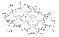
- Fig. 3 is an isometric view of an ice tray according to one aspect of the present invention.
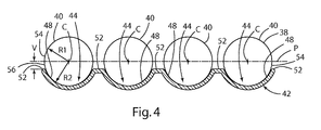
- Fig. 4 is a cross sectional view of the ice tray of Fig. 3 taken along the line IV-IV;
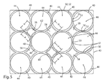
- Fig. 5 is a plan view of the ice tray of Fig. 3 ;
- Fig. 6 is a partially fragmentary cross sectional view of an ice tray according to another aspect of the present disclosure.
- an ice maker 1 includes a housing 2 and a drawer 4 that may be moved between a closed position "A" and an open position "B.”
- the drawer 4 may include a handle 6 that can be grasped by a user to thereby shift the drawer 4 from the closed position A to the open position B as shown by the arrow "X.”
- the ice maker 1 is a relatively compact unit that can be positioned on a counter top or the like.
- the ice maker one may include an upper surface 8 that is configured to support glasses 10, bottles 12, and other such items.
- housing 2 defines an internal cavity 14.
- An ice maker 16 includes first and second mold parts 18 and 19 that together define a spherical cavity 22 when the mold parts 18 and 20 are in a closed position relative to one another.
- Ice maker 1 may include an insulated refrigerator compartment 24 that is cooled by a refrigeration unit 26 disposed within housing 2.
- Refrigeration unit 26 may comprise a conventional refrigeration unit having a compressor, an evaporator, and a condenser, or it may comprise other suitable refrigeration systems. Alternatively a thermoelectric or other cooling source may be used. In other cases, it may be desirable to keep the temperature near but above freezing to avoid frost buildup in housing 2 or on the ice made.
- This may be done by driving a cooling source, such as the refrigeration unit 26, a thermoelectric or other cool sourcing, the ice mold itself, the created ice pieces or a combination thereof.
- a cooling source such as the refrigeration unit 26, a thermoelectric or other cool sourcing, the ice mold itself, the created ice pieces or a combination thereof.
- it may be preferable to keep the temperature during storage of ice spheres between 32 degrees and 50 degrees Fahrenheit, or even more preferable to maintain it between 34 and 45 degrees Fahrenheit or at some other similar range.
- Refrigeration unit 26 includes a water supply unit 28 that may supply water to the cavity 22 through a conduit 30.
- the refrigeration unit 26 may be connected to a power supply utilizing a conventional power cord and plug 32.
- the refrigeration unit 26 may also be connected to a water source utilizing a fluid conduit 36.
- the ice maker 16 may include a single spherical cavity 22 that produces one spherical piece of ice 40 at a time. Alternately, the ice maker 16 may include a plurality of spherical cavities 22 that simultaneously produce a plurality of spherical ice pieces 40. For example, with reference to Fig.
- ice maker 16 may include four spherical cavities 22 to produce four spherical pieces of ice 40 that drop into a row 46A, 46B, or 46C of ice support cavities 44 of an ice tray 42. It will be understood that the ice maker 16 may comprise a variety of devices capable of making spherical pieces of ice, and the ice maker 16 therefore does not necessarily comprise mold parts 18 and 20 as shown in Fig. 2 .
- the spherical pieces of ice 40 are positioned directly above ice support cavities 44 at the time they are released from the mold parts 18 and 20.
- the spherical pieces of ice therefore drop directly into the ice support cavities 44.
- This dropping transports the spherical pieces of ice 40 from the ice maker 16 to the cavities 44 of tray 42.
- the mold parts 18 and 20 may be shifted fore and aft in the direction of the arrow "Y" ( Fig. 2 ) to align the mold parts 18 and 19 above a specific row 46A, 46B, or 46C of tray 42 prior to opening of mold part 18.
- Refrigeration unit 26 may include a controller that is operably connected to a powered actuator (not shown) to thereby selectively shift the mold parts 18 and 20 in fore-aft directions.
- the spherical pieces of ice 40 can thereby be dropped into the cavities 44 of a selected row 46A, 46B, or 46C.
- spherical pieces of ice 40 may be transported by rails (not shown) or other suitable devices or structures to transport the spherical pieces of ice 40 from the mold parts 18 and 20 to selected ice support cavities 44.
- ice support tray 42 may include a plurality of rows 46A, 46B, and 46C of cavities 44.
- tray 42 could comprise a single row of cavities 44 if required for a particular application.
- the cavities could be arranged in such a way that rows are not formed.
- the cavities 44 are defined by concave surfaces 48.
- the concave surfaces 48 are generally spherical with a radius "R1" ( Fig. 4 ) that is substantially identical to a radius "R2" of spherical pieces of ice 40.
- Each cavity 44 defines four edges 50 that are formed by upwardly facing concave edge surfaces 52.
- Each spherical piece of ice 40 defines a radius R1 that is substantially identical to a radius R2 of concave surface 48 of ice support cavities 44.
- R1 and R2 are about 25 mm, such that ice spheres 40 have a diameter of about 50 mm.
- the ice spheres 40 (and cavities 44) may be significantly larger or smaller.
- the ice spheres are preferably about 20 mm to about 80 mm in diameter, but sizes outside this range are also possible.
- ice support cavities 44 and spherical pieces of ice 40 define coincident center points "C.”
- the center points C define a horizontal plane "P.”
- the lowermost portions of the concave edge surfaces 52 are spaced downwardly a distance "V" from the plane P.
- the distance V is preferably at least about one third or one half of the radius R1 (or R2).
- the side portions 54 of spherical pieces of ice 40 project sidewardly somewhat, thereby exposing a surface portion 56 of each spherical piece of ice 40 that is below the center plane P.
- Surface portions 56 face outwardly and downwardly. The surface 56 can therefore be grasped by a user to enable the user to pull the individual spherical pieces of ice 40 upwardly out of cavities 44.
- adjacent spherical pieces of ice 40 are spaced apart a diagonal distance "H," where the distance H is measured directly above surfaces 58.
- Surfaces 58 of tray 24 are generally planar, upwardly-facing surfaces that are disposed at the centers of four adjacent cavities 44.
- the distance H is preferably large enough to permit a user's thumb 60 and fingers to be inserted for grasping spherical pieces of ice 40.
- the distance H is preferably about 20 mm or greater, and more preferably 25 mm or more to provide clearance for a user's fingers.
- Tongs 64 or other suitable implement may be utilized to contact surface 56 to permit removal of spherical pieces of ice 40.
- the tray 42 to remain in drawer 4 during removal of spherical pieces of ice 40.
- the storage tray 42 does not necessarily need to be tipped over to remove spheres of ice 40.
- a tray 42A is similar to the tray 42 of Figs. 3-5 .
- tray 42A includes an opening 66 having a radius R3.
- Radius R3 is somewhat smaller than the radii R1 and R2. For example, if R1 and R2 are 25 mm, R3 may be 20 mm.
- Ice maker 16 may be operably connected to a switch or other sensor (not shown) whereby the ice maker is actuated and makes new ice spheres 40 once the melted spheres 40 have dropped into bin 68.
- the ice storage tray 42 is preferably made of a material having relatively low thermal conduction to thereby prevent or reduce transfer of heat from the spherical pieces of ice 40 in a manner that could otherwise cause portions of the spherical surface 38 pieces of ice 40 to melt.
- storage tray 42 is made of a polymer material having a thermal conductivity of about 2 W/°Cm.
- the tray 42 may also comprise a material having an even lower thermal conductivity of about .1 W/°Cm or less.
- the ice support cavities 44 have a concave spherical surface 48 that contacts the outer surface 38 of spherical pieces of ice 40, the spherical pieces of ice 40 do not develop irregularities in areas of contact that could otherwise occur if the support cavities 44 had a non spherical surface shape.
Landscapes
- Engineering & Computer Science (AREA)
- Physics & Mathematics (AREA)
- Mechanical Engineering (AREA)
- Thermal Sciences (AREA)
- General Engineering & Computer Science (AREA)
- Chemical & Material Sciences (AREA)
- Combustion & Propulsion (AREA)
- Production, Working, Storing, Or Distribution Of Ice (AREA)
Abstract
Description
- Various types of ice makers have been developed. Known ice makers may make ice "cubes" in the form of cubes or other shapes. However, if the ice cubes are stored together in a box-like tray or the like, the shape of the "cubes" may change due to melting of portions of the ice cubes.
- One aspect of the present invention is a method of storing spherical pieces of ice. The method includes providing a freezer having a refrigerated space that can be maintained at a temperature below the freezing point of water. The method also includes providing an ice maker configured to produce a plurality of spherical pieces of ice, each spherical piece of ice having a substantially spherical outer surface defining a first radius. The method includes providing a tray having a plurality of upwardly opening ice supporting cavities, wherein each ice support cavity has a concave surface defining a portion of a sphere having a second radius that is substantially equal to the first radius whereby spherical pieces of ice formed by the ice maker fit closely in the ice support cavities. The method further includes positioning the tray in the refrigerated space at a predefined location relative to the ice maker. Pieces of ice are transported from the ice maker to the ice support cavities, and the pieces of ice are positioned in the ice support cavities.
- These and other features, advantages, and objects of the present invention will be further understood and appreciated by those skilled in the art by reference to the following specification, claims, and appended drawings.
-
Fig. 1 is an isometric view of an ice maker including an ice tray according to one aspect of the present invention; -
Fig. 2 is a cross sectional view of the ice maker ofFig. 1 taken along the line II-II; -
Fig. 3 is an isometric view of an ice tray according to one aspect of the present invention; -
Fig. 4 is a cross sectional view of the ice tray ofFig. 3 taken along the line IV-IV; -
Fig. 5 is a plan view of the ice tray ofFig. 3 ; -
Fig. 6 is a partially fragmentary cross sectional view of an ice tray according to another aspect of the present disclosure. - For purposes of description herein, the terms "upper," "lower," "right," "left," "rear," "front," "vertical," "horizontal," and derivatives thereof shall relate to the invention as oriented in
Fig. 1 . However, it is to be understood that the invention may assume various alternative orientations and step sequences, except where expressly specified to the contrary. It is also to be understood that the specific devices and processes illustrated in the attached drawings, and described in the following specification, are simply exemplary embodiments of the inventive concepts defined in the appended claims. Hence, specific dimensions and other physical characteristics relating to the embodiments disclosed herein are not to be considered as limiting, unless the claims expressly state otherwise. - With reference to
Fig. 1 , anice maker 1 according to one aspect of the present invention includes ahousing 2 and adrawer 4 that may be moved between a closed position "A" and an open position "B." Thedrawer 4 may include ahandle 6 that can be grasped by a user to thereby shift thedrawer 4 from the closed position A to the open position B as shown by the arrow "X." In the illustrated example, theice maker 1 is a relatively compact unit that can be positioned on a counter top or the like. The ice maker one may include anupper surface 8 that is configured to supportglasses 10,bottles 12, and other such items. - With further reference to
Fig. 2 ,housing 2 defines aninternal cavity 14. Anice maker 16 includes first andsecond mold parts spherical cavity 22 when themold parts 18 and 20 are in a closed position relative to one another.Ice maker 1 may include aninsulated refrigerator compartment 24 that is cooled by arefrigeration unit 26 disposed withinhousing 2.Refrigeration unit 26 may comprise a conventional refrigeration unit having a compressor, an evaporator, and a condenser, or it may comprise other suitable refrigeration systems. Alternatively a thermoelectric or other cooling source may be used. In other cases, it may be desirable to keep the temperature near but above freezing to avoid frost buildup inhousing 2 or on the ice made. This may be done by driving a cooling source, such as therefrigeration unit 26, a thermoelectric or other cool sourcing, the ice mold itself, the created ice pieces or a combination thereof. For example it may be preferable to keep the temperature during storage of ice spheres between 32 degrees and 50 degrees Fahrenheit, or even more preferable to maintain it between 34 and 45 degrees Fahrenheit or at some other similar range. -
Refrigeration unit 26 includes awater supply unit 28 that may supply water to thecavity 22 through aconduit 30. Therefrigeration unit 26 may be connected to a power supply utilizing a conventional power cord and plug 32. Therefrigeration unit 26 may also be connected to a water source utilizing afluid conduit 36. - In use, water is supplied to the
spherical cavity 22 with themold parts 18 and 20 in the closed position. After the ice freezes to form a spherical piece ofice 40, one of themold parts 18 shifts to an open position, thereby permitting a spherical piece ofice 40 to drop into anice support cavity 44 of anice tray 42. Theice maker 16 may include a singlespherical cavity 22 that produces one spherical piece ofice 40 at a time. Alternately, theice maker 16 may include a plurality ofspherical cavities 22 that simultaneously produce a plurality ofspherical ice pieces 40. For example, with reference toFig. 3 ,ice maker 16 may include fourspherical cavities 22 to produce four spherical pieces ofice 40 that drop into arow ice support cavities 44 of anice tray 42. It will be understood that theice maker 16 may comprise a variety of devices capable of making spherical pieces of ice, and theice maker 16 therefore does not necessarily comprisemold parts 18 and 20 as shown inFig. 2 . - In the illustrated example, the spherical pieces of
ice 40 are positioned directly aboveice support cavities 44 at the time they are released from themold parts 18 and 20. The spherical pieces of ice therefore drop directly into theice support cavities 44. This dropping transports the spherical pieces ofice 40 from theice maker 16 to thecavities 44 oftray 42. Themold parts 18 and 20 may be shifted fore and aft in the direction of the arrow "Y" (Fig. 2 ) to align themold parts specific row tray 42 prior to opening ofmold part 18.Refrigeration unit 26 may include a controller that is operably connected to a powered actuator (not shown) to thereby selectively shift themold parts 18 and 20 in fore-aft directions. The spherical pieces ofice 40 can thereby be dropped into thecavities 44 of a selectedrow ice 40 may be transported by rails (not shown) or other suitable devices or structures to transport the spherical pieces ofice 40 from themold parts 18 and 20 to selectedice support cavities 44. - With reference to
Fig. 3 ,ice support tray 42 may include a plurality ofrows cavities 44. However,tray 42 could comprise a single row ofcavities 44 if required for a particular application. Furthermore, the cavities could be arranged in such a way that rows are not formed. Thecavities 44 are defined byconcave surfaces 48. Theconcave surfaces 48 are generally spherical with a radius "R1" (Fig. 4 ) that is substantially identical to a radius "R2" of spherical pieces ofice 40. Eachcavity 44 defines fouredges 50 that are formed by upwardly facingconcave edge surfaces 52. - Each spherical piece of ice 40 (
Fig. 4 ) defines a radius R1 that is substantially identical to a radius R2 ofconcave surface 48 ofice support cavities 44. In a preferred embodiment, R1 and R2 are about 25 mm, such thatice spheres 40 have a diameter of about 50 mm. However, it will be understood that the ice spheres 40 (and cavities 44) may be significantly larger or smaller. In general, the ice spheres are preferably about 20 mm to about 80 mm in diameter, but sizes outside this range are also possible. - Referring again to
Fig. 4 ,ice support cavities 44 and spherical pieces ofice 40 define coincident center points "C." The center points C define a horizontal plane "P." The lowermost portions of theconcave edge surfaces 52 are spaced downwardly a distance "V" from the plane P. The distance V is preferably at least about one third or one half of the radius R1 (or R2). Theside portions 54 of spherical pieces ofice 40 project sidewardly somewhat, thereby exposing asurface portion 56 of each spherical piece ofice 40 that is below the center planeP. Surface portions 56 face outwardly and downwardly. Thesurface 56 can therefore be grasped by a user to enable the user to pull the individual spherical pieces ofice 40 upwardly out ofcavities 44. - Also, with further reference to
Fig. 5 , adjacent spherical pieces ofice 40 are spaced apart a diagonal distance "H," where the distance H is measured directly abovesurfaces 58.Surfaces 58 oftray 24 are generally planar, upwardly-facing surfaces that are disposed at the centers of fouradjacent cavities 44. The distance H is preferably large enough to permit a user'sthumb 60 and fingers to be inserted for grasping spherical pieces ofice 40. The distance H is preferably about 20 mm or greater, and more preferably 25 mm or more to provide clearance for a user's fingers.Tongs 64 or other suitable implement may be utilized to contactsurface 56 to permit removal of spherical pieces ofice 40. This permits thetray 42 to remain indrawer 4 during removal of spherical pieces ofice 40. Thus, in contrast to known trays that are used to form ice cubes, thestorage tray 42 does not necessarily need to be tipped over to remove spheres ofice 40. - With further reference to
Fig. 6 , atray 42A according to another aspect of the present disclosure is similar to thetray 42 ofFigs. 3-5 . However,tray 42A includes anopening 66 having a radius R3. Radius R3 is somewhat smaller than the radii R1 and R2. For example, if R1 and R2 are 25 mm, R3 may be 20 mm. - As
ice sphere 40 melts, liquid water flows out of opening 66 and drips or flows into a water recovery area such as bin 68 (Fig. 2 ) positioned belowtray 42. Removal of melted water from cavity 44A reduces heat transfer fromice spheres 40 into the liquid water and thereby slows down the melting ofice spheres 40. Adrain line 70 may be connected tobin 68 to provide for drainage of water frombin 68. Referring again toFig. 6 , asice sphere 40 melts, the size of theice sphere 40 is gradually reduced. Theice sphere 40 eventually falls throughopening 66 and into bin 68 (Fig. 2 ). This automatically clears the cavities 44A.Ice maker 16 may be operably connected to a switch or other sensor (not shown) whereby the ice maker is actuated and makesnew ice spheres 40 once the meltedspheres 40 have dropped intobin 68. - The
ice storage tray 42 is preferably made of a material having relatively low thermal conduction to thereby prevent or reduce transfer of heat from the spherical pieces ofice 40 in a manner that could otherwise cause portions of thespherical surface 38 pieces ofice 40 to melt. In a preferred embodiment,storage tray 42 is made of a polymer material having a thermal conductivity of about 2 W/°Cm. Thetray 42 may also comprise a material having an even lower thermal conductivity of about .1 W/°Cm or less. Because theice support cavities 44 have a concavespherical surface 48 that contacts theouter surface 38 of spherical pieces ofice 40, the spherical pieces ofice 40 do not develop irregularities in areas of contact that could otherwise occur if thesupport cavities 44 had a non spherical surface shape. - It is also to be understood that variations and modifications can be made on the aforementioned structures and methods without departing from the concepts of the present invention, and further it is to be understood that such concepts are intended to be covered by the following claims unless these claims by their language expressly state otherwise.
Claims (12)
- A method of storing spherical pieces of ice in a freezer, the method comprising:providing an ice maker configured to produce a plurality of spherical pieces of ice, each spherical piece of ice having a substantially spherical outer surface defining a first radius;providing a tray having a plurality of upwardly opening ice support cavities, wherein each ice support cavity has a concave surface defining a portion of a sphere having a second radius that is substantially equal to the first radius whereby spherical pieces of ice formed by the ice maker fit closely in the ice support cavities;positioning the tray in the refrigerated space at a predefined location relative to the ice maker;transporting spherical pieces of ice from the ice maker to the ice support cavities;positioning the spherical pieces of ice in the ice support cavities.
- The method of claim 1, wherein:the tray comprises a material having thermal conductivity of about 2 W/°Cm or less.
- The method of claim 1 or 2, further providing:a refrigerated space that can be maintained at a temperature above but within 15 degrees Fahrenheit of the freezing point of water.
- The method of any preceding claim, wherein:the ice support cavities are arranged in a plurality of parallel rows.
- The method of any preceding claim, wherein:the freezer comprises a housing and a drawer that is movably supported by the housing; and including:positioning the tray in the drawer whereby the drawer can be moved from a closed position to an open position to permit user access to ice spheres disposed in the ice support cavities of the tray.
- The method of claim 5, including:positioning the tray below the ice maker;causing ice spheres made by the ice maker to drop into the ice support cavities.
- The method of claim 6, wherein:positioning the tray below the ice maker includes shifting the drawer from an open position to a closed position.
- The method of any preceding claim, wherein:each ice support cavity defines a center point, and the concave surfaces of each ice support cavity define edges having portions that are spaced downwardly a distance that is at least about one third of the first radius relative to a horizontal plane passing through the center point of each ice support cavity whereby surface portions of spherical pieces of ice below the horizontal plane are exposed when spherical pieces of ice are position in the ice support cavities; and including:removing spherical pieces of ice by gripping the surface portions of spherical pieces of ice that are below the horizontal planes, and lifting the spherical pieces of ice out of the ice support cavities.
- The method of claim 8, wherein:gripping the spherical pieces of ice includes grasping the spherical pieces of ice.
- The method of claim 8 or 9, wherein:gripping the spherical pieces of ice includes bringing opposed contact surfaces of a mechanical device into contact with spherical pieces of ice while the spherical pieces of ice are disposed in the ice support cavities.
- The method of any preceding claim, wherein:the concave surface has a third radius that is smaller than both the first and second radii, wherein the third radius will support the spherical ice piece as it melts and shrinks in size from its first radius to approximately the third radius, and whereafter the ice sphere melts to or past the third radius, the support structure allows it to fall.
- The method of claim 11, wherein:the fallen ice sphere is received into a water recovery area.
Applications Claiming Priority (1)
| Application Number | Priority Date | Filing Date | Title |
|---|---|---|---|
| US13/679,199 US9310116B2 (en) | 2012-11-16 | 2012-11-16 | Ice storage to hold ice and minimize melting of ice spheres |
Publications (3)
| Publication Number | Publication Date |
|---|---|
| EP2733446A2 true EP2733446A2 (en) | 2014-05-21 |
| EP2733446A3 EP2733446A3 (en) | 2016-09-28 |
| EP2733446B1 EP2733446B1 (en) | 2019-01-09 |
Family
ID=48745696
Family Applications (1)
| Application Number | Title | Priority Date | Filing Date |
|---|---|---|---|
| EP13173614.2A Active EP2733446B1 (en) | 2012-11-16 | 2013-06-25 | Method for storing spherical pieces of ice |
Country Status (2)
| Country | Link |
|---|---|
| US (3) | US9310116B2 (en) |
| EP (1) | EP2733446B1 (en) |
Families Citing this family (15)
| Publication number | Priority date | Publication date | Assignee | Title |
|---|---|---|---|---|
| WO2015009929A1 (en) * | 2013-07-18 | 2015-01-22 | Propeller, Inc. | Ice mold |
| USD847222S1 (en) * | 2017-05-16 | 2019-04-30 | The Brothers Tod | Ice ball maker |
| BR202017016643Y1 (en) * | 2017-08-02 | 2022-10-11 | Nely Cristina Braidotti Cavalari | CONSTRUCTION PROVISION APPLIED IN ICE FORM |
| US20190281858A1 (en) * | 2018-03-13 | 2019-09-19 | Sean Saeyong Kim | Food preparation system and method of use |
| US10697684B2 (en) * | 2018-03-20 | 2020-06-30 | Bsh Home Appliances Corporation | Automatic ice-sphere-making system for refrigerator appliance |
| WO2020071824A1 (en) | 2018-10-02 | 2020-04-09 | Lg Electronics Inc. | Refrigerator |
| USD894720S1 (en) * | 2018-11-13 | 2020-09-01 | Allan Wendling | Furniture riser |
| EP4336130A1 (en) | 2018-11-16 | 2024-03-13 | LG Electronics Inc. | Home appliance with an ice maker |
| US11408661B2 (en) * | 2019-06-19 | 2022-08-09 | Haier Us Appliance Solutions, Inc. | Single cord ice press assembly |
| US12072134B2 (en) | 2019-11-06 | 2024-08-27 | Abstract Ice, Inc. | Systems and methods for creating clear ice |
| CN114061188A (en) * | 2020-08-07 | 2022-02-18 | 广州科勒尔制冷设备有限公司 | Novel spherical ice maker |
| US11732944B2 (en) * | 2020-08-31 | 2023-08-22 | Singular Ice LLC | Apparatus and method for craft ice production |
| US20240027118A1 (en) | 2020-11-20 | 2024-01-25 | Abstract Ice, Inc. | Devices for producing clear ice products and related methods |
| US12571573B2 (en) | 2022-11-21 | 2026-03-10 | Abstract Ice, Inc. | Devices for producing clear ice products |
| AU2024215251A1 (en) | 2023-02-02 | 2025-08-14 | Abstract Ice, Inc. | Devices for shaping clear ice products and related methods |
Family Cites Families (33)
| Publication number | Priority date | Publication date | Assignee | Title |
|---|---|---|---|---|
| US2083081A (en) * | 1935-10-24 | 1937-06-08 | Harry H Moll | Freezing mold |
| US2247018A (en) * | 1939-05-22 | 1941-06-24 | Frank L Sessions | Ice freezing mold |
| US2461999A (en) * | 1945-04-16 | 1949-02-15 | P M Payne & Company | Separable mold and refractory trough assembly |
| US2774473A (en) * | 1952-01-31 | 1956-12-18 | Keyes Fibre Co | Support-protector for fragile articles |
| US3049259A (en) * | 1960-06-29 | 1962-08-14 | Mazzi Angelo | Cupped tray for holding fruits and the like |
| US3721103A (en) * | 1970-06-15 | 1973-03-20 | Olin Corp | Method for making hollow ice bodies |
| FI49583C (en) * | 1973-11-16 | 1975-08-11 | Kymin Oy Kymmene Ab | Fruit packing tray. |
| US3962469A (en) * | 1974-02-22 | 1976-06-08 | Diamond Fruit Growers, Inc. | Fruit tray package |
| US4081122A (en) | 1976-08-12 | 1978-03-28 | Hobson John S | Combined ice tray egg carton |
| USD249269S (en) | 1977-02-10 | 1978-09-05 | Pitts Robert E | Ice tray |
| US4162780A (en) * | 1977-05-20 | 1979-07-31 | Stone City Products, Inc. | Ice cube service |
| USD255657S (en) | 1977-10-19 | 1980-07-01 | Mobil Oil Corporation | Packaging tray or the like |
| GB2046891A (en) * | 1979-04-19 | 1980-11-19 | Shing Hsiung Wu | Improvements in or relating to making ice balls |
| US4244470A (en) * | 1979-08-06 | 1981-01-13 | Howard Johnson Company | Individual ice cream dispensing receptacle |
| USD262355S (en) | 1979-09-10 | 1981-12-22 | Oakley Thomas J | Combined egg carton and ice tray |
| US4417716A (en) * | 1982-01-27 | 1983-11-29 | Americo Penna | Novelty ice tray |
| US4910974A (en) * | 1988-01-29 | 1990-03-27 | Hoshizaki Electric Company Limited | Automatic ice making machine |
| US4970877A (en) * | 1989-02-17 | 1990-11-20 | Berge A. Dimijian | Ice forming apparatus |
| US5106103A (en) * | 1990-12-03 | 1992-04-21 | Janine Fiore | Initial game |
| US5152420A (en) * | 1991-07-31 | 1992-10-06 | Rubbermaid Incorporated | Recycle trash container |
| CN2141538Y (en) * | 1992-10-30 | 1993-09-01 | 周益人 | Ice cooling device |
| USD406595S (en) | 1997-06-04 | 1999-03-09 | Maytag Corporation | Ice cube tray |
| AT405100B (en) * | 1997-08-25 | 1999-05-25 | Spicker Harald | FOOD TONGS, ESPECIALLY ICE TONGS |
| US6168131B1 (en) | 1999-08-06 | 2001-01-02 | Business World Trade, Inc. | Ice cube tray and dispenser |
| MXPA01001917A (en) * | 2000-02-22 | 2004-07-30 | Tekni Plex Inc | Packing tray. |
| CN1455856A (en) * | 2000-09-01 | 2003-11-12 | 素村胜三 | Method and apparatus for producing stereoscopic ice of transparent sphere or the like |
| JP3588775B2 (en) * | 2001-10-17 | 2004-11-17 | 有限会社大信製作所 | Apparatus for producing molded ice blocks and method for producing molded ice blocks |
| JP2003336946A (en) * | 2002-05-16 | 2003-11-28 | Hoshizaki Electric Co Ltd | Automatic ice machinery |
| JP2004053125A (en) * | 2002-07-19 | 2004-02-19 | Daiwa Industries Ltd | Ice machine |
| US20050151050A1 (en) * | 2004-01-13 | 2005-07-14 | Michael Godfrey | Ice cube tray |
| KR20090079043A (en) * | 2008-01-16 | 2009-07-21 | 삼성전자주식회사 | Ice making unit and refrigerator |
| JP5348768B2 (en) * | 2009-08-11 | 2013-11-20 | ホシザキ電機株式会社 | Automatic ice machine |
| US8672132B2 (en) * | 2011-11-30 | 2014-03-18 | Tekni-Plex, Inc. | Packing tray with built-in drainage and method of manufacture |
-
2012
- 2012-11-16 US US13/679,199 patent/US9310116B2/en active Active
-
2013
- 2013-06-25 EP EP13173614.2A patent/EP2733446B1/en active Active
-
2016
- 2016-03-03 US US15/059,446 patent/US9677808B2/en not_active Expired - Fee Related
-
2017
- 2017-02-08 US US15/427,438 patent/US20170146275A1/en not_active Abandoned
Non-Patent Citations (1)
| Title |
|---|
| None |
Also Published As
| Publication number | Publication date |
|---|---|
| US20160187053A1 (en) | 2016-06-30 |
| US20140137576A1 (en) | 2014-05-22 |
| US9677808B2 (en) | 2017-06-13 |
| US9310116B2 (en) | 2016-04-12 |
| EP2733446A3 (en) | 2016-09-28 |
| US20170146275A1 (en) | 2017-05-25 |
| EP2733446B1 (en) | 2019-01-09 |
Similar Documents
| Publication | Publication Date | Title |
|---|---|---|
| US9310116B2 (en) | Ice storage to hold ice and minimize melting of ice spheres | |
| US7669435B2 (en) | Modular thermoelectric chilling system | |
| US9200823B2 (en) | Ice maker with thermoelectrically cooled mold for producing spherical clear ice | |
| US8925335B2 (en) | Ice cube release and rapid freeze using fluid exchange apparatus and methods | |
| MX2020006419A (en) | Direct cooling ice maker. | |
| US10859303B2 (en) | Refrigerator with ice mold chilled by air exchange cooled by fluid from freezer | |
| US20090064707A1 (en) | Fast freeze shelf | |
| EP2938938B1 (en) | Ice maker | |
| US10655901B2 (en) | Refrigerator with ice mold chilled by fluid exchange from thermoelectric device with cooling from fresh food compartment of freezer compartment | |
| KR101661615B1 (en) | Apparatus and method for making ice in refrigerator | |
| US20130145777A1 (en) | Clear ice making machine | |
| US7661275B2 (en) | Ice making method and machine with PETD harvest | |
| JP2013234811A (en) | Ice making device and refrigerator | |
| KR19990036004A (en) | Refrigerator | |
| US9752813B2 (en) | Refrigerator with thermoelectric device control process for an icemaker | |
| US9714784B2 (en) | Refrigerator with icemaker chilled by thermoelectric device cooled by fresh food compartment air | |
| US20140150468A1 (en) | Modular cooling and low energy ice | |
| JP2021506912A (en) | Devices and methods for freezing at least a portion of a biological sample | |
| EP2738486A2 (en) | Modular cooling and low energy ice | |
| US9593874B2 (en) | Ice mold for bottleneck | |
| KR100565607B1 (en) | Refrigerator ice maker | |
| JP2524920B2 (en) | Cooling method of ice storage room of automatic ice machine for block ice | |
| JPH0532980U (en) | Ice storage chamber structure of automatic ice machine for block ice | |
| US2800775A (en) | Freezing device | |
| KR20130009527A (en) | Ice making method for ice maker |
Legal Events
| Date | Code | Title | Description |
|---|---|---|---|
| PUAI | Public reference made under article 153(3) epc to a published international application that has entered the european phase |
Free format text: ORIGINAL CODE: 0009012 |
|
| 17P | Request for examination filed |
Effective date: 20130625 |
|
| AK | Designated contracting states |
Kind code of ref document: A2 Designated state(s): AL AT BE BG CH CY CZ DE DK EE ES FI FR GB GR HR HU IE IS IT LI LT LU LV MC MK MT NL NO PL PT RO RS SE SI SK SM TR |
|
| AX | Request for extension of the european patent |
Extension state: BA ME |
|
| PUAL | Search report despatched |
Free format text: ORIGINAL CODE: 0009013 |
|
| AK | Designated contracting states |
Kind code of ref document: A3 Designated state(s): AL AT BE BG CH CY CZ DE DK EE ES FI FR GB GR HR HU IE IS IT LI LT LU LV MC MK MT NL NO PL PT RO RS SE SI SK SM TR |
|
| AX | Request for extension of the european patent |
Extension state: BA ME |
|
| RIC1 | Information provided on ipc code assigned before grant |
Ipc: F25C 5/18 20060101AFI20160825BHEP |
|
| STAA | Information on the status of an ep patent application or granted ep patent |
Free format text: STATUS: REQUEST FOR EXAMINATION WAS MADE |
|
| R17P | Request for examination filed (corrected) |
Effective date: 20170323 |
|
| RBV | Designated contracting states (corrected) |
Designated state(s): AL AT BE BG CH CY CZ DE DK EE ES FI FR GB GR HR HU IE IS IT LI LT LU LV MC MK MT NL NO PL PT RO RS SE SI SK SM TR |
|
| STAA | Information on the status of an ep patent application or granted ep patent |
Free format text: STATUS: EXAMINATION IS IN PROGRESS |
|
| 17Q | First examination report despatched |
Effective date: 20170803 |
|
| GRAP | Despatch of communication of intention to grant a patent |
Free format text: ORIGINAL CODE: EPIDOSNIGR1 |
|
| STAA | Information on the status of an ep patent application or granted ep patent |
Free format text: STATUS: GRANT OF PATENT IS INTENDED |
|
| INTG | Intention to grant announced |
Effective date: 20181008 |
|
| GRAS | Grant fee paid |
Free format text: ORIGINAL CODE: EPIDOSNIGR3 |
|
| GRAA | (expected) grant |
Free format text: ORIGINAL CODE: 0009210 |
|
| STAA | Information on the status of an ep patent application or granted ep patent |
Free format text: STATUS: THE PATENT HAS BEEN GRANTED |
|
| AK | Designated contracting states |
Kind code of ref document: B1 Designated state(s): AL AT BE BG CH CY CZ DE DK EE ES FI FR GB GR HR HU IE IS IT LI LT LU LV MC MK MT NL NO PL PT RO RS SE SI SK SM TR |
|
| REG | Reference to a national code |
Ref country code: GB Ref legal event code: FG4D |
|
| REG | Reference to a national code |
Ref country code: CH Ref legal event code: EP Ref country code: AT Ref legal event code: REF Ref document number: 1087822 Country of ref document: AT Kind code of ref document: T Effective date: 20190115 |
|
| REG | Reference to a national code |
Ref country code: DE Ref legal event code: R096 Ref document number: 602013049461 Country of ref document: DE |
|
| REG | Reference to a national code |
Ref country code: IE Ref legal event code: FG4D |
|
| REG | Reference to a national code |
Ref country code: NL Ref legal event code: MP Effective date: 20190109 |
|
| REG | Reference to a national code |
Ref country code: LT Ref legal event code: MG4D |
|
| PG25 | Lapsed in a contracting state [announced via postgrant information from national office to epo] |
Ref country code: NL Free format text: LAPSE BECAUSE OF FAILURE TO SUBMIT A TRANSLATION OF THE DESCRIPTION OR TO PAY THE FEE WITHIN THE PRESCRIBED TIME-LIMIT Effective date: 20190109 |
|
| REG | Reference to a national code |
Ref country code: AT Ref legal event code: MK05 Ref document number: 1087822 Country of ref document: AT Kind code of ref document: T Effective date: 20190109 |
|
| PG25 | Lapsed in a contracting state [announced via postgrant information from national office to epo] |
Ref country code: SE Free format text: LAPSE BECAUSE OF FAILURE TO SUBMIT A TRANSLATION OF THE DESCRIPTION OR TO PAY THE FEE WITHIN THE PRESCRIBED TIME-LIMIT Effective date: 20190109 Ref country code: ES Free format text: LAPSE BECAUSE OF FAILURE TO SUBMIT A TRANSLATION OF THE DESCRIPTION OR TO PAY THE FEE WITHIN THE PRESCRIBED TIME-LIMIT Effective date: 20190109 Ref country code: PL Free format text: LAPSE BECAUSE OF FAILURE TO SUBMIT A TRANSLATION OF THE DESCRIPTION OR TO PAY THE FEE WITHIN THE PRESCRIBED TIME-LIMIT Effective date: 20190109 Ref country code: LT Free format text: LAPSE BECAUSE OF FAILURE TO SUBMIT A TRANSLATION OF THE DESCRIPTION OR TO PAY THE FEE WITHIN THE PRESCRIBED TIME-LIMIT Effective date: 20190109 Ref country code: FI Free format text: LAPSE BECAUSE OF FAILURE TO SUBMIT A TRANSLATION OF THE DESCRIPTION OR TO PAY THE FEE WITHIN THE PRESCRIBED TIME-LIMIT Effective date: 20190109 Ref country code: NO Free format text: LAPSE BECAUSE OF FAILURE TO SUBMIT A TRANSLATION OF THE DESCRIPTION OR TO PAY THE FEE WITHIN THE PRESCRIBED TIME-LIMIT Effective date: 20190409 Ref country code: PT Free format text: LAPSE BECAUSE OF FAILURE TO SUBMIT A TRANSLATION OF THE DESCRIPTION OR TO PAY THE FEE WITHIN THE PRESCRIBED TIME-LIMIT Effective date: 20190509 |
|
| PG25 | Lapsed in a contracting state [announced via postgrant information from national office to epo] |
Ref country code: IS Free format text: LAPSE BECAUSE OF FAILURE TO SUBMIT A TRANSLATION OF THE DESCRIPTION OR TO PAY THE FEE WITHIN THE PRESCRIBED TIME-LIMIT Effective date: 20190509 Ref country code: GR Free format text: LAPSE BECAUSE OF FAILURE TO SUBMIT A TRANSLATION OF THE DESCRIPTION OR TO PAY THE FEE WITHIN THE PRESCRIBED TIME-LIMIT Effective date: 20190410 Ref country code: BG Free format text: LAPSE BECAUSE OF FAILURE TO SUBMIT A TRANSLATION OF THE DESCRIPTION OR TO PAY THE FEE WITHIN THE PRESCRIBED TIME-LIMIT Effective date: 20190409 Ref country code: LV Free format text: LAPSE BECAUSE OF FAILURE TO SUBMIT A TRANSLATION OF THE DESCRIPTION OR TO PAY THE FEE WITHIN THE PRESCRIBED TIME-LIMIT Effective date: 20190109 Ref country code: RS Free format text: LAPSE BECAUSE OF FAILURE TO SUBMIT A TRANSLATION OF THE DESCRIPTION OR TO PAY THE FEE WITHIN THE PRESCRIBED TIME-LIMIT Effective date: 20190109 Ref country code: HR Free format text: LAPSE BECAUSE OF FAILURE TO SUBMIT A TRANSLATION OF THE DESCRIPTION OR TO PAY THE FEE WITHIN THE PRESCRIBED TIME-LIMIT Effective date: 20190109 |
|
| REG | Reference to a national code |
Ref country code: DE Ref legal event code: R097 Ref document number: 602013049461 Country of ref document: DE |
|
| PG25 | Lapsed in a contracting state [announced via postgrant information from national office to epo] |
Ref country code: CZ Free format text: LAPSE BECAUSE OF FAILURE TO SUBMIT A TRANSLATION OF THE DESCRIPTION OR TO PAY THE FEE WITHIN THE PRESCRIBED TIME-LIMIT Effective date: 20190109 Ref country code: RO Free format text: LAPSE BECAUSE OF FAILURE TO SUBMIT A TRANSLATION OF THE DESCRIPTION OR TO PAY THE FEE WITHIN THE PRESCRIBED TIME-LIMIT Effective date: 20190109 Ref country code: AL Free format text: LAPSE BECAUSE OF FAILURE TO SUBMIT A TRANSLATION OF THE DESCRIPTION OR TO PAY THE FEE WITHIN THE PRESCRIBED TIME-LIMIT Effective date: 20190109 Ref country code: SK Free format text: LAPSE BECAUSE OF FAILURE TO SUBMIT A TRANSLATION OF THE DESCRIPTION OR TO PAY THE FEE WITHIN THE PRESCRIBED TIME-LIMIT Effective date: 20190109 Ref country code: EE Free format text: LAPSE BECAUSE OF FAILURE TO SUBMIT A TRANSLATION OF THE DESCRIPTION OR TO PAY THE FEE WITHIN THE PRESCRIBED TIME-LIMIT Effective date: 20190109 Ref country code: DK Free format text: LAPSE BECAUSE OF FAILURE TO SUBMIT A TRANSLATION OF THE DESCRIPTION OR TO PAY THE FEE WITHIN THE PRESCRIBED TIME-LIMIT Effective date: 20190109 Ref country code: AT Free format text: LAPSE BECAUSE OF FAILURE TO SUBMIT A TRANSLATION OF THE DESCRIPTION OR TO PAY THE FEE WITHIN THE PRESCRIBED TIME-LIMIT Effective date: 20190109 |
|
| PLBE | No opposition filed within time limit |
Free format text: ORIGINAL CODE: 0009261 |
|
| STAA | Information on the status of an ep patent application or granted ep patent |
Free format text: STATUS: NO OPPOSITION FILED WITHIN TIME LIMIT |
|
| PG25 | Lapsed in a contracting state [announced via postgrant information from national office to epo] |
Ref country code: SM Free format text: LAPSE BECAUSE OF FAILURE TO SUBMIT A TRANSLATION OF THE DESCRIPTION OR TO PAY THE FEE WITHIN THE PRESCRIBED TIME-LIMIT Effective date: 20190109 |
|
| 26N | No opposition filed |
Effective date: 20191010 |
|
| PG25 | Lapsed in a contracting state [announced via postgrant information from national office to epo] |
Ref country code: MC Free format text: LAPSE BECAUSE OF FAILURE TO SUBMIT A TRANSLATION OF THE DESCRIPTION OR TO PAY THE FEE WITHIN THE PRESCRIBED TIME-LIMIT Effective date: 20190109 |
|
| REG | Reference to a national code |
Ref country code: CH Ref legal event code: PL |
|
| PG25 | Lapsed in a contracting state [announced via postgrant information from national office to epo] |
Ref country code: SI Free format text: LAPSE BECAUSE OF FAILURE TO SUBMIT A TRANSLATION OF THE DESCRIPTION OR TO PAY THE FEE WITHIN THE PRESCRIBED TIME-LIMIT Effective date: 20190109 |
|
| REG | Reference to a national code |
Ref country code: BE Ref legal event code: MM Effective date: 20190630 |
|
| PG25 | Lapsed in a contracting state [announced via postgrant information from national office to epo] |
Ref country code: TR Free format text: LAPSE BECAUSE OF FAILURE TO SUBMIT A TRANSLATION OF THE DESCRIPTION OR TO PAY THE FEE WITHIN THE PRESCRIBED TIME-LIMIT Effective date: 20190109 |
|
| PG25 | Lapsed in a contracting state [announced via postgrant information from national office to epo] |
Ref country code: IE Free format text: LAPSE BECAUSE OF NON-PAYMENT OF DUE FEES Effective date: 20190625 |
|
| PG25 | Lapsed in a contracting state [announced via postgrant information from national office to epo] |
Ref country code: LI Free format text: LAPSE BECAUSE OF NON-PAYMENT OF DUE FEES Effective date: 20190630 Ref country code: LU Free format text: LAPSE BECAUSE OF NON-PAYMENT OF DUE FEES Effective date: 20190625 Ref country code: BE Free format text: LAPSE BECAUSE OF NON-PAYMENT OF DUE FEES Effective date: 20190630 Ref country code: CH Free format text: LAPSE BECAUSE OF NON-PAYMENT OF DUE FEES Effective date: 20190630 |
|
| PG25 | Lapsed in a contracting state [announced via postgrant information from national office to epo] |
Ref country code: CY Free format text: LAPSE BECAUSE OF FAILURE TO SUBMIT A TRANSLATION OF THE DESCRIPTION OR TO PAY THE FEE WITHIN THE PRESCRIBED TIME-LIMIT Effective date: 20190109 |
|
| PG25 | Lapsed in a contracting state [announced via postgrant information from national office to epo] |
Ref country code: MT Free format text: LAPSE BECAUSE OF FAILURE TO SUBMIT A TRANSLATION OF THE DESCRIPTION OR TO PAY THE FEE WITHIN THE PRESCRIBED TIME-LIMIT Effective date: 20190109 Ref country code: HU Free format text: LAPSE BECAUSE OF FAILURE TO SUBMIT A TRANSLATION OF THE DESCRIPTION OR TO PAY THE FEE WITHIN THE PRESCRIBED TIME-LIMIT; INVALID AB INITIO Effective date: 20130625 |
|
| PG25 | Lapsed in a contracting state [announced via postgrant information from national office to epo] |
Ref country code: MK Free format text: LAPSE BECAUSE OF FAILURE TO SUBMIT A TRANSLATION OF THE DESCRIPTION OR TO PAY THE FEE WITHIN THE PRESCRIBED TIME-LIMIT Effective date: 20190109 |
|
| P01 | Opt-out of the competence of the unified patent court (upc) registered |
Effective date: 20230522 |
|
| PGFP | Annual fee paid to national office [announced via postgrant information from national office to epo] |
Ref country code: FR Payment date: 20240625 Year of fee payment: 12 |
|
| PGFP | Annual fee paid to national office [announced via postgrant information from national office to epo] |
Ref country code: IT Payment date: 20240619 Year of fee payment: 12 |
|
| PGFP | Annual fee paid to national office [announced via postgrant information from national office to epo] |
Ref country code: DE Payment date: 20250626 Year of fee payment: 13 |
|
| PGFP | Annual fee paid to national office [announced via postgrant information from national office to epo] |
Ref country code: GB Payment date: 20250617 Year of fee payment: 13 |
|
| PG25 | Lapsed in a contracting state [announced via postgrant information from national office to epo] |
Ref country code: IT Free format text: LAPSE BECAUSE OF NON-PAYMENT OF DUE FEES Effective date: 20250625 |
|
| PG25 | Lapsed in a contracting state [announced via postgrant information from national office to epo] |
Ref country code: FR Free format text: LAPSE BECAUSE OF NON-PAYMENT OF DUE FEES Effective date: 20250630 |