EP2733421A1 - Can-annular combustor array for a gas turbine having oval can heads twisted among themselves - Google Patents
Can-annular combustor array for a gas turbine having oval can heads twisted among themselves Download PDFInfo
- Publication number
- EP2733421A1 EP2733421A1 EP13184858.2A EP13184858A EP2733421A1 EP 2733421 A1 EP2733421 A1 EP 2733421A1 EP 13184858 A EP13184858 A EP 13184858A EP 2733421 A1 EP2733421 A1 EP 2733421A1
- Authority
- EP
- European Patent Office
- Prior art keywords
- combustor
- array
- clocked
- orientation
- cans
- Prior art date
- Legal status (The legal status is an assumption and is not a legal conclusion. Google has not performed a legal analysis and makes no representation as to the accuracy of the status listed.)
- Granted
Links
- 239000000446 fuel Substances 0.000 claims abstract description 35
- 230000009467 reduction Effects 0.000 claims abstract description 5
- 238000000034 method Methods 0.000 claims description 7
- 239000007789 gas Substances 0.000 description 18
- 238000010586 diagram Methods 0.000 description 10
- 230000007704 transition Effects 0.000 description 9
- 230000001427 coherent effect Effects 0.000 description 5
- 239000000567 combustion gas Substances 0.000 description 4
- 238000003491 array Methods 0.000 description 3
- 238000013459 approach Methods 0.000 description 2
- 238000001816 cooling Methods 0.000 description 2
- 230000003993 interaction Effects 0.000 description 2
- VNWKTOKETHGBQD-UHFFFAOYSA-N methane Chemical compound C VNWKTOKETHGBQD-UHFFFAOYSA-N 0.000 description 2
- 239000000203 mixture Substances 0.000 description 2
- 238000012986 modification Methods 0.000 description 2
- 230000004048 modification Effects 0.000 description 2
- 238000002485 combustion reaction Methods 0.000 description 1
- 238000013461 design Methods 0.000 description 1
- 239000003345 natural gas Substances 0.000 description 1
- 230000010355 oscillation Effects 0.000 description 1
- 238000010248 power generation Methods 0.000 description 1
- 238000012552 review Methods 0.000 description 1
- 238000004513 sizing Methods 0.000 description 1
Images






Classifications
-
- F—MECHANICAL ENGINEERING; LIGHTING; HEATING; WEAPONS; BLASTING
- F02—COMBUSTION ENGINES; HOT-GAS OR COMBUSTION-PRODUCT ENGINE PLANTS
- F02C—GAS-TURBINE PLANTS; AIR INTAKES FOR JET-PROPULSION PLANTS; CONTROLLING FUEL SUPPLY IN AIR-BREATHING JET-PROPULSION PLANTS
- F02C7/00—Features, components parts, details or accessories, not provided for in, or of interest apart form groups F02C1/00 - F02C6/00; Air intakes for jet-propulsion plants
- F02C7/24—Heat or noise insulation
-
- F—MECHANICAL ENGINEERING; LIGHTING; HEATING; WEAPONS; BLASTING
- F23—COMBUSTION APPARATUS; COMBUSTION PROCESSES
- F23C—METHODS OR APPARATUS FOR COMBUSTION USING FLUID FUEL OR SOLID FUEL SUSPENDED IN A CARRIER GAS OR AIR
- F23C5/00—Disposition of burners with respect to the combustion chamber or to one another; Mounting of burners in combustion apparatus
- F23C5/08—Disposition of burners
-
- F—MECHANICAL ENGINEERING; LIGHTING; HEATING; WEAPONS; BLASTING
- F23—COMBUSTION APPARATUS; COMBUSTION PROCESSES
- F23R—GENERATING COMBUSTION PRODUCTS OF HIGH PRESSURE OR HIGH VELOCITY, e.g. GAS-TURBINE COMBUSTION CHAMBERS
- F23R3/00—Continuous combustion chambers using liquid or gaseous fuel
- F23R3/42—Continuous combustion chambers using liquid or gaseous fuel characterised by the arrangement or form of the flame tubes or combustion chambers
- F23R3/46—Combustion chambers comprising an annular arrangement of several essentially tubular flame tubes within a common annular casing or within individual casings
-
- F—MECHANICAL ENGINEERING; LIGHTING; HEATING; WEAPONS; BLASTING
- F23—COMBUSTION APPARATUS; COMBUSTION PROCESSES
- F23R—GENERATING COMBUSTION PRODUCTS OF HIGH PRESSURE OR HIGH VELOCITY, e.g. GAS-TURBINE COMBUSTION CHAMBERS
- F23R2900/00—Special features of, or arrangements for continuous combustion chambers; Combustion processes therefor
- F23R2900/00014—Reducing thermo-acoustic vibrations by passive means, e.g. by Helmholtz resonators
Definitions
- the present application and the resultant patent relate generally to gas turbine engines and more particularly relate to an array of non-circular head end combustors arranged in a clocked
- Combustor cans in a multiple can array may communicate acoustically with each other.
- Large pressure oscillations also known as combustion dynamics, may result when heat release fluctuations couple with combustor can acoustic tones.
- Some of these combustor can acoustic tones may be in-phase with the tones of an adjacent can while other tones may be out-of-phase.
- the in-phase tones may excite the turbine blades in the hot gas path if the tones coincide with the natural frequency of the blades.
- the in-phase tones may be particularly of concern when the instabilities in different combustor cans are coherent, i.e., a strong relationship in the frequency and the amplitude of the instability in one can to the next can.
- Such coherent in-phase tones may excite the turbine buckets so as to lead to durability issues and thereby limit the operability of the gas turbine engine.
- tuning may provide cans of different volume and length so as to limit the amplitude of the in-phase coherent tones near the bucket natural frequencies as compared to typical design practice limits. These tuning techniques thus may mean that the overall operability space may be limited by the in-phase coherent tones. Moreover, a significant amount of time and resources may be required to achieve frequency avoidance between the combustor and the turbine components. Further, frequency avoidance may only as accurate as the predictive capability used to achieve such.
- the present invention provides a clocked combustor can array for coherence reduction in a gas turbine engine.
- the clocked combustor can array may include a number of combustor cans positioned in a circumferential array.
- a first set of the combustor cans may have a first orientation and a second set of the combustor cans may have a second orientation.
- the present invention further provides a method of operating a combustor can array with reduced coherence.
- the method may include the steps of positioning a first set of combustor cans at a first orientation, operating the first set of combustor cans in a first tone, positioning a second set of combustor cans at a second orientation, and operating the second set of combustor cans in a second tone.
- the present invention provides a clocked combustor can array for coherence reduction in a gas turbine engine.
- the clocked combustor can array may include a number of combustor cans positioned in a circumferential array. Each of the combustor cans may include a non-circular head end.
- a first set of the combustor cans may have a first orientation and a second set of the combustor cans may have a second orientation.
- Fig. 1 shows a schematic diagram of gas turbine engine 10 as may be used herein.
- the gas turbine engine 10 may include a compressor 15.
- the compressor 15 compresses an incoming flow of air 20.
- the compressor 15 delivers the compressed flow of air 20 to a number of combustor cans 25.
- the combustor cans 25 mix the compressed flow of air 20 with a pressurized flow of fuel 30 and ignite the mixture to create a flow of hot combustion gases 35.
- the gas turbine engine 10 may include any number of combustor cans 25.
- the flow of the hot combustion gases 35 is in turn delivered to a turbine 40.
- the flow of the hot combustion gases 35 drives the turbine 40 so as to produce mechanical work.
- the mechanical work produced in the turbine 40 drives the compressor 15 via a shaft 45 and an external load 50 such as an electrical generator and the like.
- the gas turbine engine 10 may use natural gas, various types of syngas, and/or other types of fuels.
- the gas turbine engine 10 may be any one of a number of different gas turbine engines offered by General Electric Company of Schenectady, New York, including, but not limited to, those such as a 7 or a 9 series heavy duty gas turbine engine and the like.
- the gas turbine engine 10 may have different configurations and may use other types of components.
- Other types of gas turbine engines also may be used herein.
- Multiple gas turbine engines, other types of turbines, and other types of power generation equipment also may be used herein together.
- Fig. 3 and Fig. 4 show a portion of a combustor can 100 as may be described herein.
- the combustor can 100 may be a one-piece combustor can 110 with an integrated configuration of the transition piece 80, the liner 82, and the first stage nozzle vane 90.
- Other types of combustors 100 may be used herein with other components and other configurations.
- the combustor can 110 may include a head end 120. A number of fuel nozzles 130 may extend from an end cover (not shown) to a cap 140.
- the combustor can 110 also may be configured as an integrated piece 150. As described above, the integrated piece 150 may include the liner, the transition piece, and the first stage nozzle. The integrated piece 150 may extend from the head end 120 to an aft end 160 about a first stage bucket blade 170 of the turbine 40 and the like. An impingement sleeve 180 may surround the integrated piece 150 so as to provide a flow of cooling air 20 thereto from the compressor 15 or elsewhere. Other components and other configurations also may be used herein.
- the head end 120 may have a substantially non-circular configuration 190.
- the non-circular configuration 190 is not limited to any particular shape.
- the head end 120 thus may be an oval head end 200, an elliptical head end 210, or any type of substantially non-circular head end 220.
- the cap 140 also may have the non-circular configurations 190.
- the cap 140 may be an oval cap 230, an elliptical cap 240, or any type of substantially non-circular cap 250.
- a transition piece 155 of the integrated piece 150 about the head end 120 also may have the non-circular configuration 190 before transitioning into any other shape.
- the clocked combustor cans 380 may mitigate interaction between combustor tones and the turbine buckets.
- the clocked combustor arrays described herein maintain uniform combustor sizing while varying the clocking of the combustor cans 110. By altering the circumferential orientation with respect to neighboring combustor cans 110, relative flame characteristics of the individual combustor cans may be effectively changed for reduced coherence.
- Fig. 9 and Fig. 10 show examples of the fuel nozzles 130 that may be used with the combustor cans described herein.
- the fuel nozzles 130 may have a number of swozzle vanes 420 thereon.
- the swozzle (swirler + nozzle) vanes 420 may have a number of fuel ports positioned about a number of extending vanes so as to inject a flow fuel 30 into the flow of air 20 so as to promote good premixing.
- Fig. 9 shows a number of clockwise swozzle vanes 430.
- Fig. 10 shows a number of counter-clockwise swozzle vanes 440.
- the clockwise or counter-clockwise vanes 430, 440 thus impart that direction to the flow of air 20 therethrough.
- the swozzle vanes 420 may have any size, shape, or configuration.
- oriented swirler vanes also may be used herein.
- micro-mixers also may be used.
- Fig. 11 shows a combustor can 450 with six (6) fuel nozzles 130 with the clockwise swozzle vanes 430 in a six (6) around zero (0) configuration 460.
- Fig. 12 shows a combustor can 470 with a five (5) around one (1) configuration 480. In these examples, all of the fuel nozzles 130 may have the clockwise swozzle vanes 430.
- Fig. 13 shows a combustor can 490 with the six (6) around zero (0) configuration 460. In this example, the fuel nozzle 130 may have alternating counter-clockwise swozzle vanes 440 and clockwise swozzle vanes 430.
- Fig. 11 shows a combustor can 450 with six (6) fuel nozzles 130 with the clockwise swozzle vanes 430 in a six (6) around zero (0) configuration 460.
- Fig. 12 shows a combustor can 470 with a five (5) around one (1) configuration 480
- FIG. 14 shows a combustor can 500 with the five (5) around one (1) configuration 480.
- a center fuel nozzle 510 may have the counter-clockwise swozzle vanes 440 while a number of the outer fuel nozzles 520 may have the clockwise swozzle vanes 430.
- Any of the fuel nozzles 130 in the combustors described herein may have the clockwise configuration 430 or the counter-clockwise configuration 440 in any number or position.
- Fig. 15 shows a circumferential array 530 with a number of combustor cans 540 in five (5) around one (1) configuration 480 having fuel nozzles 130 with the clockwise configuration 430.
- Fig. 16 shows a circumferential array 550 with a number of combustor cans 560 having the five (5) around one (1) orientation 480 with a number of the center fuel nozzles 510 having the counter-clockwise orientation 440 while the outer fuel nozzles 520 have the clockwise orientation 430.
- Fig. 17 shows a circumferential array 570 with a number of combustor cans 580 in the six (6) around zero (0) orientation 460.
- the swozzle vanes 420 may alter the flame characteristics, flame to flame interactions, and corresponding dynamics behavior in either an individual combustor or a circumferential array. Specifically, the direction of the swozzle vanes or other types of vanes may be altered while the remaining hardware configurations may stay substantially unchanged.
- the use of the swozzle vanes and the like thus may be an alternative and a lower cost approach for coherence breaking as opposed to combustors with different volumes and lengths.
Landscapes
- Engineering & Computer Science (AREA)
- Chemical & Material Sciences (AREA)
- Combustion & Propulsion (AREA)
- Mechanical Engineering (AREA)
- General Engineering & Computer Science (AREA)
- Turbine Rotor Nozzle Sealing (AREA)
- Structures Of Non-Positive Displacement Pumps (AREA)
- Combustion Of Fluid Fuel (AREA)
Abstract
Description
- The present application and the resultant patent relate generally to gas turbine engines and more particularly relate to an array of non-circular head end combustors arranged in a clocked
- Combustor cans in a multiple can array may communicate acoustically with each other. Large pressure oscillations, also known as combustion dynamics, may result when heat release fluctuations couple with combustor can acoustic tones. Some of these combustor can acoustic tones may be in-phase with the tones of an adjacent can while other tones may be out-of-phase. The in-phase tones may excite the turbine blades in the hot gas path if the tones coincide with the natural frequency of the blades. The in-phase tones may be particularly of concern when the instabilities in different combustor cans are coherent, i.e., a strong relationship in the frequency and the amplitude of the instability in one can to the next can. Such coherent in-phase tones may excite the turbine buckets so as to lead to durability issues and thereby limit the operability of the gas turbine engine.
- Current solutions to these potentially damaging in-phase coherent tones focus on combustor tuning. Such tuning may provide cans of different volume and length so as to limit the amplitude of the in-phase coherent tones near the bucket natural frequencies as compared to typical design practice limits. These tuning techniques thus may mean that the overall operability space may be limited by the in-phase coherent tones. Moreover, a significant amount of time and resources may be required to achieve frequency avoidance between the combustor and the turbine components. Further, frequency avoidance may only as accurate as the predictive capability used to achieve such.
- There is thus a desire for improved systems and methods for coherence reduction between combustor components and turbine components without requiring combustor tuning and other types of conventional frequency avoidance techniques. Preferably, such systems and methods may reduce overall coherence so as to improve component lifetime without compromising system efficiency and output and without requiring extensive modifications.
- The present invention provides a clocked combustor can array for coherence reduction in a gas turbine engine. The clocked combustor can array may include a number of combustor cans positioned in a circumferential array. A first set of the combustor cans may have a first orientation and a second set of the combustor cans may have a second orientation.
- The present invention further provides a method of operating a combustor can array with reduced coherence. The method may include the steps of positioning a first set of combustor cans at a first orientation, operating the first set of combustor cans in a first tone, positioning a second set of combustor cans at a second orientation, and operating the second set of combustor cans in a second tone.
- The present invention provides a clocked combustor can array for coherence reduction in a gas turbine engine. The clocked combustor can array may include a number of combustor cans positioned in a circumferential array. Each of the combustor cans may include a non-circular head end. A first set of the combustor cans may have a first orientation and a second set of the combustor cans may have a second orientation.
- These and other features and improvements of the present application and the resultant patent will become apparent to one of ordinary skill in the art upon review of the following detailed description when taken in conjunction with the several drawings and the appended claims.
-
-
Fig. 1 is a schematic diagram of a gas turbine engine with a compressor, a combustor, a turbine, and a load. -
Fig. 2 is a schematic diagram of a combustor as may be used with the gas turbine engine ofFig. 1 . -
Fig. 3 is a partial perspective view of a combustor with a non-circular head end as may be described herein. -
Fig. 4 is a partial sectional view of the non-circular head end of the combustor ofFig. 3 . -
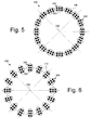
Fig. 5 is a schematic view of a combustor can array. -
Fig. 6 is a schematic view of an alternative embodiment of a combustor can array. -
Fig. 7 is a schematic view of a clocked combustor can array as may be described herein. -
Fig. 8 is a schematic view of an alternative embodiment of a clocked combustor can array as may be described herein. -
Fig. 9 is a partial perspective view of a fuel nozzle with clockwise swozzle vanes. -
Fig. 10 is a partial perspective view of a fuel nozzle with counter-clockwise swozzle vanes. -
Fig. 11 is a schematic diagram of a combustor with fuel nozzles in a six (6) around zero (0) configuration with clockwise swozzle vanes. -
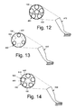
Fig. 12 is a schematic diagram of a combustor with fuel nozzles in a five (5) around one (1) configuration with clockwise swozzle vanes. -
Fig. 13 is a schematic diagram of a combustor with fuel nozzles in a six (6) around zero (0) configuration with fuel nozzle having alternating clockwise swozzle vanes and counter-clockwise swozzle vanes. -
Fig. 14 is a schematic diagram of a combustor with fuel nozzles in a five (5) around one (1) configuration with a center fuel nozzle having counter-clockwise swozzle vanes and the outer fuel nozzles having clockwise swozzle vanes. -
Fig. 15 is a schematic diagram of a circumferential array of combustors with fuel nozzles in a five (5) around one (1) configuration with clockwise swozzle vanes. -
Fig. 16 is a schematic diagram of a circumferential array of combustors in a five (5) around one (1) configuration with some of the center fuel nozzles having a counter-clockwise orientation. -
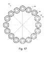
Fig. 17 is a schematic diagram of a circumferential array of combustors in a six (6) around zero (0) configuration with some of the combustors having fuel nozzles with alternating clockwise swozzle vanes and counter-clockwise swozzle vanes. - Referring now to the drawings, in which like numerals refer to like elements throughout the several views,
Fig. 1 shows a schematic diagram ofgas turbine engine 10 as may be used herein. Thegas turbine engine 10 may include acompressor 15. Thecompressor 15 compresses an incoming flow ofair 20. Thecompressor 15 delivers the compressed flow ofair 20 to a number ofcombustor cans 25. The combustor cans 25 mix the compressed flow ofair 20 with a pressurized flow offuel 30 and ignite the mixture to create a flow ofhot combustion gases 35. Although only a single combustor can 25 is shown, thegas turbine engine 10 may include any number ofcombustor cans 25. The flow of thehot combustion gases 35 is in turn delivered to aturbine 40. The flow of thehot combustion gases 35 drives theturbine 40 so as to produce mechanical work. The mechanical work produced in theturbine 40 drives thecompressor 15 via ashaft 45 and anexternal load 50 such as an electrical generator and the like. - The
gas turbine engine 10 may use natural gas, various types of syngas, and/or other types of fuels. Thegas turbine engine 10 may be any one of a number of different gas turbine engines offered by General Electric Company of Schenectady, New York, including, but not limited to, those such as a 7 or a 9 series heavy duty gas turbine engine and the like. Thegas turbine engine 10 may have different configurations and may use other types of components. Other types of gas turbine engines also may be used herein. Multiple gas turbine engines, other types of turbines, and other types of power generation equipment also may be used herein together. -
Fig. 2 shows an example of the combustor can 25 that may be used with thegas turbine engine 10. The combustor can 25 may include ahead end 60 with a number offuel nozzles 65 positioned between anend cover 70 and acircular cap 75. Atransition piece 80 and aliner 82 may be attached to each other and may extend from thecircular cap 75 to anaft end 85 near a firststage nozzle vane 90 of theturbine 40. Animpingement sleeve 95 may surround thetransition piece 80 and theliner 82 to provide a cooling flow of air thereto. The combustor can 25 described herein is for the purpose of example only. Combustor cans with other components and other configurations may be used herein. -
Fig. 3 and Fig. 4 show a portion of a combustor can 100 as may be described herein. As above, the combustor can 100 may be a one-piece combustor can 110 with an integrated configuration of thetransition piece 80, theliner 82, and the firststage nozzle vane 90. Other types ofcombustors 100 may be used herein with other components and other configurations. - The combustor can 110 may include a
head end 120. A number offuel nozzles 130 may extend from an end cover (not shown) to acap 140. The combustor can 110 also may be configured as anintegrated piece 150. As described above, theintegrated piece 150 may include the liner, the transition piece, and the first stage nozzle. Theintegrated piece 150 may extend from thehead end 120 to anaft end 160 about a firststage bucket blade 170 of theturbine 40 and the like. Animpingement sleeve 180 may surround theintegrated piece 150 so as to provide a flow of coolingair 20 thereto from thecompressor 15 or elsewhere. Other components and other configurations also may be used herein. - The
head end 120 may have a substantiallynon-circular configuration 190. Thenon-circular configuration 190 is not limited to any particular shape. Thehead end 120 thus may be an oval head end 200, an elliptical head end 210, or any type of substantially non-circular head end 220. Similarly, thecap 140 also may have thenon-circular configurations 190. As a result, thecap 140 may be an oval cap 230, an elliptical cap 240, or any type of substantially non-circular cap 250. Likewise, atransition piece 155 of theintegrated piece 150 about thehead end 120 also may have thenon-circular configuration 190 before transitioning into any other shape. As a result, an oval transition piece 260, an elliptical transition piece 270, or any type of substantially non-circular transition piece 280 may be used herein. Thecombustor cans 110 with thehead end 120 having thenon-circular configuration 190 thus may promote a more efficient transition of the flow ofhot combustion gases 35 to thefirst stage bucket 170 of theturbine 40 with lower total pressure losses. Other components and other configurations also may be used herein. -
Fig. 5 shows an example of acombustor can array 290. The combustor canarray 290 may include any number of thecombustor cans 110. Each of thecombustor cans 110 may have thehead end 120 with thenon-circular configuration 190 such as that described above. Thecombustor cans 110 may be positioned in acircumferential array 300. In this example, thecombustor cans 110 of the combustor canarray 290 may have ahorizontal position 310 in which along side 320 of thenon-circular configuration 190 faces acenter point 330 of thecircumferential array 300.Fig. 6 shows a further example of acombustor can array 340. In this example, thecombustor cans 110 may have a substantiallyvertical position 350 in which ashort side 360 of the non-circular configuration faces thecenter point 330. Other components and other configurations may be used herein. -
Fig. 7 shows an example of a clocked combustor canarray 370 as may be described herein. In this example, the clocked combustor canarray 370 may include a first set 375 of clockedcombustor cans 380 in a first orientation 385. The clockedcombustor cans 380 may be "clocked" or rotated about ninety degrees (90°) as compared to the combustor canarray 290 ofFig. 5 or the combustor canarray 340 ofFig. 6 with a second set 390 of the combustor cans in the original or a second orientation 400. Although six (6) clockedcombustor cans 320 are shown, any number may be used at any angle. - For example,
Fig. 8 shows a clocked combustor canarray 410 with a configuration that may be the reverse of that of the clocked combustor canarray 370 ofFig. 7 . In this example, ten (10) of thecombustor cans 110 may be the clockedcombustor cans 380 in the first orientation 385 and the remaining six (6)combustor cans 110 may be in their original or second orientation 400. Any combination ofcombustor cans 110 in any orientation may be used herein. Other components and other configurations may be used herein. - In use, the clocked
combustor cans 380 may mitigate interaction between combustor tones and the turbine buckets. As opposed to traditional combustor tuning approaches in which combustor cans of different volumes and lengths may be required for reducing coherence, the clocked combustor arrays described herein maintain uniform combustor sizing while varying the clocking of thecombustor cans 110. By altering the circumferential orientation with respect to neighboringcombustor cans 110, relative flame characteristics of the individual combustor cans may be effectively changed for reduced coherence. -
Fig. 9 and Fig. 10 show examples of thefuel nozzles 130 that may be used with the combustor cans described herein. Thefuel nozzles 130 may have a number ofswozzle vanes 420 thereon. The swozzle (swirler + nozzle)vanes 420 may have a number of fuel ports positioned about a number of extending vanes so as to inject aflow fuel 30 into the flow ofair 20 so as to promote good premixing.Fig. 9 shows a number of clockwiseswozzle vanes 430.Fig. 10 shows a number of counter-clockwiseswozzle vanes 440. The clockwise orcounter-clockwise vanes air 20 therethrough. Theswozzle vanes 420 may have any size, shape, or configuration. Similarly oriented swirler vanes also may be used herein. Likewise, micro-mixers also may be used. -
Fig. 11 shows a combustor can 450 with six (6)fuel nozzles 130 with the clockwiseswozzle vanes 430 in a six (6) around zero (0)configuration 460.Fig. 12 shows a combustor can 470 with a five (5) around one (1)configuration 480. In these examples, all of thefuel nozzles 130 may have the clockwiseswozzle vanes 430.Fig. 13 shows a combustor can 490 with the six (6) around zero (0)configuration 460. In this example, thefuel nozzle 130 may have alternating counter-clockwiseswozzle vanes 440 and clockwiseswozzle vanes 430.Fig. 14 shows a combustor can 500 with the five (5) around one (1)configuration 480. In this example, acenter fuel nozzle 510 may have the counter-clockwiseswozzle vanes 440 while a number of theouter fuel nozzles 520 may have the clockwiseswozzle vanes 430. Any of thefuel nozzles 130 in the combustors described herein may have theclockwise configuration 430 or thecounter-clockwise configuration 440 in any number or position. - Likewise, entire arrays of combustor cans may be similarly oriented.
Fig. 15 shows acircumferential array 530 with a number ofcombustor cans 540 in five (5) around one (1)configuration 480 havingfuel nozzles 130 with theclockwise configuration 430.Fig. 16 shows acircumferential array 550 with a number ofcombustor cans 560 having the five (5) around one (1)orientation 480 with a number of thecenter fuel nozzles 510 having thecounter-clockwise orientation 440 while theouter fuel nozzles 520 have theclockwise orientation 430.Fig. 17 shows acircumferential array 570 with a number ofcombustor cans 580 in the six (6) around zero (0)orientation 460. In this example, thefuel nozzles 130 ofcertain combustor cans 500 may have theclockwise configuration 430 while the others have thecounter-clockwise configuration 440. The circumferential arrays thus may have combustor cans with any configuration and with any type of fuel nozzles and swozzle vanes in any number, position, or direction. - In use, the
swozzle vanes 420 may alter the flame characteristics, flame to flame interactions, and corresponding dynamics behavior in either an individual combustor or a circumferential array. Specifically, the direction of the swozzle vanes or other types of vanes may be altered while the remaining hardware configurations may stay substantially unchanged. The use of the swozzle vanes and the like thus may be an alternative and a lower cost approach for coherence breaking as opposed to combustors with different volumes and lengths. - It should be apparent that the foregoing relates only to certain embodiments of the present application and the resultant patent. Numerous changes and modifications may be made herein by one of ordinary skill in the art without departing from the general spirit and scope of the invention as defined by the following claims and the equivalents thereof.
Claims (15)
- A clocked combustor can array (370,410) for coherence reduction in a gas turbine engine (10), comprising:a plurality of combustor cans (380) positioned in a circumferential array (300);a first set (375) of the plurality of combustor cans (380) comprising a first orientation (385); anda second set (390) of the plurality of combustor cans (380) comprising a second orientation (400).
- The clocked combustor can array of claim 1, wherein each of the plurality of combustors cans (380) comprises a non-circular (190) head end (120).
- The clocked combustor can array of claim 2, wherein the non-circular (190) head end (120) comprises an oval head end (200) or an elliptical head end (210).
- The clocked combustor can array of any of claims 1 to 3, wherein the first orientation (385) comprises a horizontal orientation (310).
- The clocked combustor can array of any of claims 1 to 4, wherein the first set (375) of combustor cans (380) comprises a long side (320) facing a center point (330) of the circumferential array (300).
- The clocked combustor array of any of claims 1 to 3, wherein the first orientation (385) comprises a vertical orientation (350).
- The clocked combustor can array of claim 1 to 3 and 6, wherein the first set (375) of combustor cans (380) comprises a short side (360) facing a center point (330) of the circumferential array (300).
- The clocked combustor can array of any preceding claim, wherein the first orientation (385) comprises a clocked position of about ninety degrees from the second orientation (400).
- The clocked combustor can array of any preceding claim, wherein the first orientation (385) comprises a plurality of fuel nozzles (130) with clockwise vanes thereon (430).
- The clocked combustor can array of any of claim 1 to 8, wherein the first orientation (385) comprises a plurality of fuel nozzles (130) with counter-clockwise (440) vanes thereon.
- The clocked combustor can array of any of claims 1 to 10, wherein the first orientation (385) comprises a plurality of fuel nozzles (130) with clockwise vanes (430) and counter-clock wise vanes (440) thereon.
- The clocked combustor can array of any preceding claim, wherein the plurality of combustor cans (380) comprises a six (6) around zero (0) configuration.
- The clocked combustor can array of any of claims 1 to 11, wherein the plurality of combustor cans comprises a five (5) around one (1) configuration.
- The clocked combustor can array of any preceding claim, wherein the plurality of combustor cans comprises one piece combustor cans.
- A method of operating a combustor can array (370,410) with reduced coherence, comprising:positioning a first set (375) of combustor cans (380) in a first orientation (385);operating the first set (375) of combustor cans (380) at a first tone;positioning a second set (390) of combustor cans (380) in a second orientation (400); andoperating the second set (390) of combustor cans (380) at a second tone.
Applications Claiming Priority (1)
| Application Number | Priority Date | Filing Date | Title |
|---|---|---|---|
| US13/681,453 US9546601B2 (en) | 2012-11-20 | 2012-11-20 | Clocked combustor can array |
Publications (2)
| Publication Number | Publication Date |
|---|---|
| EP2733421A1 true EP2733421A1 (en) | 2014-05-21 |
| EP2733421B1 EP2733421B1 (en) | 2017-03-15 |
Family
ID=49231270
Family Applications (1)
| Application Number | Title | Priority Date | Filing Date |
|---|---|---|---|
| EP13184858.2A Not-in-force EP2733421B1 (en) | 2012-11-20 | 2013-09-17 | Can-annular combustor array for a gas turbine having oval or elliptical can heads twisted among themselves |
Country Status (4)
| Country | Link |
|---|---|
| US (1) | US9546601B2 (en) |
| EP (1) | EP2733421B1 (en) |
| JP (1) | JP2014102064A (en) |
| CN (1) | CN103835809B (en) |
Families Citing this family (9)
| Publication number | Priority date | Publication date | Assignee | Title |
|---|---|---|---|---|
| US9145778B2 (en) * | 2012-04-03 | 2015-09-29 | General Electric Company | Combustor with non-circular head end |
| US9709279B2 (en) | 2014-02-27 | 2017-07-18 | General Electric Company | System and method for control of combustion dynamics in combustion system |
| US9845956B2 (en) * | 2014-04-09 | 2017-12-19 | General Electric Company | System and method for control of combustion dynamics in combustion system |
| US9677767B2 (en) * | 2014-05-29 | 2017-06-13 | Siemens Energy, Inc. | Combustion turbine with Siamesed wall paired combustor housings |
| WO2016057009A1 (en) | 2014-10-06 | 2016-04-14 | Siemens Aktiengesellschaft | Combustor and method for damping vibrational modes under high-frequency combustion dynamics |
| EP3015770B1 (en) * | 2014-11-03 | 2020-07-01 | Ansaldo Energia Switzerland AG | Can combustion chamber |
| US10113747B2 (en) * | 2015-04-15 | 2018-10-30 | General Electric Company | Systems and methods for control of combustion dynamics in combustion system |
| US9897322B2 (en) | 2015-07-07 | 2018-02-20 | General Electric Company | Combustor assembly for a gas turbine engine and method of making same |
| US12339002B2 (en) | 2022-04-29 | 2025-06-24 | General Electric Company | Propulsion system for jet noise reduction |
Citations (5)
| Publication number | Priority date | Publication date | Assignee | Title |
|---|---|---|---|---|
| US2072731A (en) * | 1934-12-03 | 1937-03-02 | Steam Motors Inc | Oil burner |
| DE768019C (en) * | 1939-05-26 | 1955-05-12 | Messerschmitt Boelkow Blohm | Internal combustion turbine operating with constant pressure combustion, especially for jet engines |
| GB925349A (en) * | 1958-12-03 | 1963-05-08 | Lucas Industries Ltd | Improvements relating to prime movers incorporating gas turbines |
| DE102010060363A1 (en) * | 2009-11-09 | 2011-05-12 | General Electric Company | Gas turbine fuel nozzles with opposite twist |
| EP2647799A2 (en) * | 2012-04-03 | 2013-10-09 | General Electric Company | Combustor with non-circular head end |
Family Cites Families (27)
| Publication number | Priority date | Publication date | Assignee | Title |
|---|---|---|---|---|
| GB595286A (en) * | 1942-01-08 | 1947-12-01 | ||
| BE461591A (en) * | 1944-03-16 | |||
| GB626044A (en) * | 1945-06-21 | 1949-07-08 | Bristol Aeroplane Co Ltd | Improvements in or relating to gas turbine power plants |
| GB616635A (en) * | 1946-09-13 | 1949-01-25 | Donald Louis Mordell | Improvements relating to gas-turbine engines |
| US3000182A (en) * | 1960-04-01 | 1961-09-19 | United Aircraft Corp | Can burner design |
| NL268838A (en) * | 1960-09-13 | |||
| US3238718A (en) * | 1964-01-30 | 1966-03-08 | Boeing Co | Gas turbine engine |
| US3657883A (en) * | 1970-07-17 | 1972-04-25 | Westinghouse Electric Corp | Combustion chamber clustering structure |
| US4356693A (en) * | 1980-04-22 | 1982-11-02 | Rolls-Royce Limited | Gas turbine engine combustion chambers |
| DE3661224D1 (en) * | 1985-02-26 | 1988-12-22 | Bbc Brown Boveri & Cie | Gas turbine combustor |
| US5946902A (en) * | 1997-10-01 | 1999-09-07 | Siemens Aktiengesellschaft | Gas turbine engine with tilted burners |
| SE9802707L (en) * | 1998-08-11 | 2000-02-12 | Abb Ab | Burner chamber device and method for reducing the influence of acoustic pressure fluctuations in a burner chamber device |
| US6572330B2 (en) * | 2001-03-29 | 2003-06-03 | General Electric Company | Methods and apparatus for preferential placement of turbine nozzles and shrouds based on inlet conditions |
| US6772583B2 (en) * | 2002-09-11 | 2004-08-10 | Siemens Westinghouse Power Corporation | Can combustor for a gas turbine engine |
| US6840048B2 (en) | 2002-09-26 | 2005-01-11 | General Electric Company | Dynamically uncoupled can combustor |
| US7107773B2 (en) * | 2003-09-04 | 2006-09-19 | Siemens Power Generation, Inc. | Turbine engine sequenced combustion |
| GB2454247A (en) * | 2007-11-02 | 2009-05-06 | Siemens Ag | A Combustor for a Gas-Turbine Engine Has a Burner Head with Fuel Delivered at a Compound Angle |
| US7950215B2 (en) * | 2007-11-20 | 2011-05-31 | Siemens Energy, Inc. | Sequential combustion firing system for a fuel system of a gas turbine engine |
| US8079804B2 (en) * | 2008-09-18 | 2011-12-20 | Siemens Energy, Inc. | Cooling structure for outer surface of a gas turbine case |
| US8230688B2 (en) * | 2008-09-29 | 2012-07-31 | Siemens Energy, Inc. | Modular transvane assembly |
| US20100192578A1 (en) | 2009-01-30 | 2010-08-05 | General Electric Company | System and method for suppressing combustion instability in a turbomachine |
| US20100205972A1 (en) * | 2009-02-17 | 2010-08-19 | General Electric Company | One-piece can combustor with heat transfer surface enhacements |
| US8739511B1 (en) * | 2009-05-05 | 2014-06-03 | Majed Toqan | Can-annular combustor with staged and tangential fuel-air nozzles for use on gas turbine engines |
| US8408004B2 (en) * | 2009-06-16 | 2013-04-02 | General Electric Company | Resonator assembly for mitigating dynamics in gas turbines |
| US20110048022A1 (en) * | 2009-08-29 | 2011-03-03 | General Electric Company | System and method for combustion dynamics control of gas turbine |
| US20110072826A1 (en) * | 2009-09-25 | 2011-03-31 | General Electric Company | Can to can modal decoupling using can-level fuel splits |
| US20110091829A1 (en) * | 2009-10-20 | 2011-04-21 | Vinayak Barve | Multi-fuel combustion system |
-
2012
- 2012-11-20 US US13/681,453 patent/US9546601B2/en not_active Expired - Fee Related
-
2013
- 2013-09-13 JP JP2013189963A patent/JP2014102064A/en not_active Ceased
- 2013-09-17 EP EP13184858.2A patent/EP2733421B1/en not_active Not-in-force
- 2013-09-18 CN CN201310426757.2A patent/CN103835809B/en not_active Expired - Fee Related
Patent Citations (5)
| Publication number | Priority date | Publication date | Assignee | Title |
|---|---|---|---|---|
| US2072731A (en) * | 1934-12-03 | 1937-03-02 | Steam Motors Inc | Oil burner |
| DE768019C (en) * | 1939-05-26 | 1955-05-12 | Messerschmitt Boelkow Blohm | Internal combustion turbine operating with constant pressure combustion, especially for jet engines |
| GB925349A (en) * | 1958-12-03 | 1963-05-08 | Lucas Industries Ltd | Improvements relating to prime movers incorporating gas turbines |
| DE102010060363A1 (en) * | 2009-11-09 | 2011-05-12 | General Electric Company | Gas turbine fuel nozzles with opposite twist |
| EP2647799A2 (en) * | 2012-04-03 | 2013-10-09 | General Electric Company | Combustor with non-circular head end |
Also Published As
| Publication number | Publication date |
|---|---|
| JP2014102064A (en) | 2014-06-05 |
| US20140137535A1 (en) | 2014-05-22 |
| EP2733421B1 (en) | 2017-03-15 |
| CN103835809A (en) | 2014-06-04 |
| CN103835809B (en) | 2018-03-30 |
| US9546601B2 (en) | 2017-01-17 |
Similar Documents
| Publication | Publication Date | Title |
|---|---|---|
| US9546601B2 (en) | Clocked combustor can array | |
| US8733108B2 (en) | Combustor and combustor screech mitigation methods | |
| EP2642208B1 (en) | Systems and methods for dampening combustor dynamics in a micromixer | |
| US20140238026A1 (en) | Fuel nozzle for reducing modal coupling of combustion dynamics | |
| US10030872B2 (en) | Combustor mixing joint with flow disruption surface | |
| EP2589751A2 (en) | Turbine last stage flow path | |
| US20150167979A1 (en) | First stage nozzle or transition nozzle configured to promote mixing of respective combustion streams downstream thereof before entry into a first stage bucket of a turbine | |
| US9145778B2 (en) | Combustor with non-circular head end | |
| JP2016180584A (en) | Injection boss for unibody combustor | |
| EP2758713A1 (en) | Combustor cap for damping low frequency dynamics | |
| US11125090B2 (en) | First-stage stationary vane of gas turbine and gas turbine | |
| EP2618052A1 (en) | Fuel Nozzle | |
| US20140013754A1 (en) | Power augmentation system with dynamics damping | |
| US9528703B2 (en) | Micro-mixer fuel plenum and methods for fuel tube installation | |
| CN102235668B (en) | For equipment and the method for burner | |
| EP2647800B1 (en) | Transition nozzle combustion system | |
| US9175855B2 (en) | Combustion nozzle with floating aft plate | |
| US20140033719A1 (en) | Multi-step combustor | |
| CN103717970A (en) | Combustor with bi-directional manifold for dynamics damping |
Legal Events
| Date | Code | Title | Description |
|---|---|---|---|
| PUAI | Public reference made under article 153(3) epc to a published international application that has entered the european phase |
Free format text: ORIGINAL CODE: 0009012 |
|
| 17P | Request for examination filed |
Effective date: 20130917 |
|
| AK | Designated contracting states |
Kind code of ref document: A1 Designated state(s): AL AT BE BG CH CY CZ DE DK EE ES FI FR GB GR HR HU IE IS IT LI LT LU LV MC MK MT NL NO PL PT RO RS SE SI SK SM TR |
|
| AX | Request for extension of the european patent |
Extension state: BA ME |
|
| R17P | Request for examination filed (corrected) |
Effective date: 20141121 |
|
| RBV | Designated contracting states (corrected) |
Designated state(s): AL AT BE BG CH CY CZ DE DK EE ES FI FR GB GR HR HU IE IS IT LI LT LU LV MC MK MT NL NO PL PT RO RS SE SI SK SM TR |
|
| 17Q | First examination report despatched |
Effective date: 20160302 |
|
| GRAP | Despatch of communication of intention to grant a patent |
Free format text: ORIGINAL CODE: EPIDOSNIGR1 |
|
| INTG | Intention to grant announced |
Effective date: 20161116 |
|
| GRAJ | Information related to disapproval of communication of intention to grant by the applicant or resumption of examination proceedings by the epo deleted |
Free format text: ORIGINAL CODE: EPIDOSDIGR1 |
|
| GRAR | Information related to intention to grant a patent recorded |
Free format text: ORIGINAL CODE: EPIDOSNIGR71 |
|
| GRAS | Grant fee paid |
Free format text: ORIGINAL CODE: EPIDOSNIGR3 |
|
| GRAA | (expected) grant |
Free format text: ORIGINAL CODE: 0009210 |
|
| INTC | Intention to grant announced (deleted) | ||
| INTG | Intention to grant announced |
Effective date: 20170202 |
|
| AK | Designated contracting states |
Kind code of ref document: B1 Designated state(s): AL AT BE BG CH CY CZ DE DK EE ES FI FR GB GR HR HU IE IS IT LI LT LU LV MC MK MT NL NO PL PT RO RS SE SI SK SM TR |
|
| REG | Reference to a national code |
Ref country code: CH Ref legal event code: EP Ref country code: GB Ref legal event code: FG4D |
|
| REG | Reference to a national code |
Ref country code: IE Ref legal event code: FG4D |
|
| REG | Reference to a national code |
Ref country code: AT Ref legal event code: REF Ref document number: 875971 Country of ref document: AT Kind code of ref document: T Effective date: 20170415 |
|
| REG | Reference to a national code |
Ref country code: DE Ref legal event code: R096 Ref document number: 602013018504 Country of ref document: DE |
|
| REG | Reference to a national code |
Ref country code: NL Ref legal event code: MP Effective date: 20170315 |
|
| REG | Reference to a national code |
Ref country code: LT Ref legal event code: MG4D |
|
| PG25 | Lapsed in a contracting state [announced via postgrant information from national office to epo] |
Ref country code: GR Free format text: LAPSE BECAUSE OF FAILURE TO SUBMIT A TRANSLATION OF THE DESCRIPTION OR TO PAY THE FEE WITHIN THE PRESCRIBED TIME-LIMIT Effective date: 20170616 Ref country code: LT Free format text: LAPSE BECAUSE OF FAILURE TO SUBMIT A TRANSLATION OF THE DESCRIPTION OR TO PAY THE FEE WITHIN THE PRESCRIBED TIME-LIMIT Effective date: 20170315 Ref country code: HR Free format text: LAPSE BECAUSE OF FAILURE TO SUBMIT A TRANSLATION OF THE DESCRIPTION OR TO PAY THE FEE WITHIN THE PRESCRIBED TIME-LIMIT Effective date: 20170315 Ref country code: NO Free format text: LAPSE BECAUSE OF FAILURE TO SUBMIT A TRANSLATION OF THE DESCRIPTION OR TO PAY THE FEE WITHIN THE PRESCRIBED TIME-LIMIT Effective date: 20170615 Ref country code: FI Free format text: LAPSE BECAUSE OF FAILURE TO SUBMIT A TRANSLATION OF THE DESCRIPTION OR TO PAY THE FEE WITHIN THE PRESCRIBED TIME-LIMIT Effective date: 20170315 |
|
| REG | Reference to a national code |
Ref country code: AT Ref legal event code: MK05 Ref document number: 875971 Country of ref document: AT Kind code of ref document: T Effective date: 20170315 |
|
| PG25 | Lapsed in a contracting state [announced via postgrant information from national office to epo] |
Ref country code: BG Free format text: LAPSE BECAUSE OF FAILURE TO SUBMIT A TRANSLATION OF THE DESCRIPTION OR TO PAY THE FEE WITHIN THE PRESCRIBED TIME-LIMIT Effective date: 20170615 Ref country code: RS Free format text: LAPSE BECAUSE OF FAILURE TO SUBMIT A TRANSLATION OF THE DESCRIPTION OR TO PAY THE FEE WITHIN THE PRESCRIBED TIME-LIMIT Effective date: 20170315 Ref country code: LV Free format text: LAPSE BECAUSE OF FAILURE TO SUBMIT A TRANSLATION OF THE DESCRIPTION OR TO PAY THE FEE WITHIN THE PRESCRIBED TIME-LIMIT Effective date: 20170315 Ref country code: SE Free format text: LAPSE BECAUSE OF FAILURE TO SUBMIT A TRANSLATION OF THE DESCRIPTION OR TO PAY THE FEE WITHIN THE PRESCRIBED TIME-LIMIT Effective date: 20170315 |
|
| PG25 | Lapsed in a contracting state [announced via postgrant information from national office to epo] |
Ref country code: NL Free format text: LAPSE BECAUSE OF FAILURE TO SUBMIT A TRANSLATION OF THE DESCRIPTION OR TO PAY THE FEE WITHIN THE PRESCRIBED TIME-LIMIT Effective date: 20170315 |
|
| PG25 | Lapsed in a contracting state [announced via postgrant information from national office to epo] |
Ref country code: ES Free format text: LAPSE BECAUSE OF FAILURE TO SUBMIT A TRANSLATION OF THE DESCRIPTION OR TO PAY THE FEE WITHIN THE PRESCRIBED TIME-LIMIT Effective date: 20170315 Ref country code: CZ Free format text: LAPSE BECAUSE OF FAILURE TO SUBMIT A TRANSLATION OF THE DESCRIPTION OR TO PAY THE FEE WITHIN THE PRESCRIBED TIME-LIMIT Effective date: 20170315 Ref country code: SK Free format text: LAPSE BECAUSE OF FAILURE TO SUBMIT A TRANSLATION OF THE DESCRIPTION OR TO PAY THE FEE WITHIN THE PRESCRIBED TIME-LIMIT Effective date: 20170315 Ref country code: EE Free format text: LAPSE BECAUSE OF FAILURE TO SUBMIT A TRANSLATION OF THE DESCRIPTION OR TO PAY THE FEE WITHIN THE PRESCRIBED TIME-LIMIT Effective date: 20170315 Ref country code: RO Free format text: LAPSE BECAUSE OF FAILURE TO SUBMIT A TRANSLATION OF THE DESCRIPTION OR TO PAY THE FEE WITHIN THE PRESCRIBED TIME-LIMIT Effective date: 20170315 Ref country code: AT Free format text: LAPSE BECAUSE OF FAILURE TO SUBMIT A TRANSLATION OF THE DESCRIPTION OR TO PAY THE FEE WITHIN THE PRESCRIBED TIME-LIMIT Effective date: 20170315 |
|
| PG25 | Lapsed in a contracting state [announced via postgrant information from national office to epo] |
Ref country code: PT Free format text: LAPSE BECAUSE OF FAILURE TO SUBMIT A TRANSLATION OF THE DESCRIPTION OR TO PAY THE FEE WITHIN THE PRESCRIBED TIME-LIMIT Effective date: 20170717 Ref country code: PL Free format text: LAPSE BECAUSE OF FAILURE TO SUBMIT A TRANSLATION OF THE DESCRIPTION OR TO PAY THE FEE WITHIN THE PRESCRIBED TIME-LIMIT Effective date: 20170315 Ref country code: SM Free format text: LAPSE BECAUSE OF FAILURE TO SUBMIT A TRANSLATION OF THE DESCRIPTION OR TO PAY THE FEE WITHIN THE PRESCRIBED TIME-LIMIT Effective date: 20170315 Ref country code: IS Free format text: LAPSE BECAUSE OF FAILURE TO SUBMIT A TRANSLATION OF THE DESCRIPTION OR TO PAY THE FEE WITHIN THE PRESCRIBED TIME-LIMIT Effective date: 20170715 |
|
| REG | Reference to a national code |
Ref country code: DE Ref legal event code: R097 Ref document number: 602013018504 Country of ref document: DE |
|
| PLBE | No opposition filed within time limit |
Free format text: ORIGINAL CODE: 0009261 |
|
| STAA | Information on the status of an ep patent application or granted ep patent |
Free format text: STATUS: NO OPPOSITION FILED WITHIN TIME LIMIT |
|
| PG25 | Lapsed in a contracting state [announced via postgrant information from national office to epo] |
Ref country code: DK Free format text: LAPSE BECAUSE OF FAILURE TO SUBMIT A TRANSLATION OF THE DESCRIPTION OR TO PAY THE FEE WITHIN THE PRESCRIBED TIME-LIMIT Effective date: 20170315 |
|
| 26N | No opposition filed |
Effective date: 20171218 |
|
| PG25 | Lapsed in a contracting state [announced via postgrant information from national office to epo] |
Ref country code: SI Free format text: LAPSE BECAUSE OF FAILURE TO SUBMIT A TRANSLATION OF THE DESCRIPTION OR TO PAY THE FEE WITHIN THE PRESCRIBED TIME-LIMIT Effective date: 20170315 |
|
| REG | Reference to a national code |
Ref country code: CH Ref legal event code: PL |
|
| GBPC | Gb: european patent ceased through non-payment of renewal fee |
Effective date: 20170917 |
|
| PG25 | Lapsed in a contracting state [announced via postgrant information from national office to epo] |
Ref country code: MC Free format text: LAPSE BECAUSE OF FAILURE TO SUBMIT A TRANSLATION OF THE DESCRIPTION OR TO PAY THE FEE WITHIN THE PRESCRIBED TIME-LIMIT Effective date: 20170315 |
|
| REG | Reference to a national code |
Ref country code: IE Ref legal event code: MM4A |
|
| REG | Reference to a national code |
Ref country code: BE Ref legal event code: MM Effective date: 20170930 |
|
| PG25 | Lapsed in a contracting state [announced via postgrant information from national office to epo] |
Ref country code: LU Free format text: LAPSE BECAUSE OF NON-PAYMENT OF DUE FEES Effective date: 20170917 |
|
| REG | Reference to a national code |
Ref country code: FR Ref legal event code: ST Effective date: 20180531 |
|
| PG25 | Lapsed in a contracting state [announced via postgrant information from national office to epo] |
Ref country code: GB Free format text: LAPSE BECAUSE OF NON-PAYMENT OF DUE FEES Effective date: 20170917 Ref country code: IE Free format text: LAPSE BECAUSE OF NON-PAYMENT OF DUE FEES Effective date: 20170917 Ref country code: CH Free format text: LAPSE BECAUSE OF NON-PAYMENT OF DUE FEES Effective date: 20170930 Ref country code: LI Free format text: LAPSE BECAUSE OF NON-PAYMENT OF DUE FEES Effective date: 20170930 |
|
| PG25 | Lapsed in a contracting state [announced via postgrant information from national office to epo] |
Ref country code: FR Free format text: LAPSE BECAUSE OF NON-PAYMENT OF DUE FEES Effective date: 20171002 Ref country code: BE Free format text: LAPSE BECAUSE OF NON-PAYMENT OF DUE FEES Effective date: 20170930 |
|
| PG25 | Lapsed in a contracting state [announced via postgrant information from national office to epo] |
Ref country code: MT Free format text: LAPSE BECAUSE OF NON-PAYMENT OF DUE FEES Effective date: 20170917 |
|
| PG25 | Lapsed in a contracting state [announced via postgrant information from national office to epo] |
Ref country code: HU Free format text: LAPSE BECAUSE OF FAILURE TO SUBMIT A TRANSLATION OF THE DESCRIPTION OR TO PAY THE FEE WITHIN THE PRESCRIBED TIME-LIMIT; INVALID AB INITIO Effective date: 20130917 |
|
| PG25 | Lapsed in a contracting state [announced via postgrant information from national office to epo] |
Ref country code: CY Free format text: LAPSE BECAUSE OF NON-PAYMENT OF DUE FEES Effective date: 20170315 |
|
| PGFP | Annual fee paid to national office [announced via postgrant information from national office to epo] |
Ref country code: DE Payment date: 20190820 Year of fee payment: 7 Ref country code: IT Payment date: 20190829 Year of fee payment: 7 |
|
| PG25 | Lapsed in a contracting state [announced via postgrant information from national office to epo] |
Ref country code: MK Free format text: LAPSE BECAUSE OF FAILURE TO SUBMIT A TRANSLATION OF THE DESCRIPTION OR TO PAY THE FEE WITHIN THE PRESCRIBED TIME-LIMIT Effective date: 20170315 |
|
| PG25 | Lapsed in a contracting state [announced via postgrant information from national office to epo] |
Ref country code: TR Free format text: LAPSE BECAUSE OF FAILURE TO SUBMIT A TRANSLATION OF THE DESCRIPTION OR TO PAY THE FEE WITHIN THE PRESCRIBED TIME-LIMIT Effective date: 20170315 |
|
| PG25 | Lapsed in a contracting state [announced via postgrant information from national office to epo] |
Ref country code: AL Free format text: LAPSE BECAUSE OF FAILURE TO SUBMIT A TRANSLATION OF THE DESCRIPTION OR TO PAY THE FEE WITHIN THE PRESCRIBED TIME-LIMIT Effective date: 20170315 |
|
| REG | Reference to a national code |
Ref country code: DE Ref legal event code: R119 Ref document number: 602013018504 Country of ref document: DE |
|
| PG25 | Lapsed in a contracting state [announced via postgrant information from national office to epo] |
Ref country code: DE Free format text: LAPSE BECAUSE OF NON-PAYMENT OF DUE FEES Effective date: 20210401 |
|
| PG25 | Lapsed in a contracting state [announced via postgrant information from national office to epo] |
Ref country code: IT Free format text: LAPSE BECAUSE OF NON-PAYMENT OF DUE FEES Effective date: 20200917 |