EP2733406A1 - Pipe cover, pipe structure and vehicle - Google Patents
Pipe cover, pipe structure and vehicle Download PDFInfo
- Publication number
- EP2733406A1 EP2733406A1 EP12810601.0A EP12810601A EP2733406A1 EP 2733406 A1 EP2733406 A1 EP 2733406A1 EP 12810601 A EP12810601 A EP 12810601A EP 2733406 A1 EP2733406 A1 EP 2733406A1
- Authority
- EP
- European Patent Office
- Prior art keywords
- pipe
- heat radiation
- section
- heat
- pipe cover
- Prior art date
- Legal status (The legal status is an assumption and is not a legal conclusion. Google has not performed a legal analysis and makes no representation as to the accuracy of the status listed.)
- Granted
Links
Images


Classifications
-
- F—MECHANICAL ENGINEERING; LIGHTING; HEATING; WEAPONS; BLASTING
- F16—ENGINEERING ELEMENTS AND UNITS; GENERAL MEASURES FOR PRODUCING AND MAINTAINING EFFECTIVE FUNCTIONING OF MACHINES OR INSTALLATIONS; THERMAL INSULATION IN GENERAL
- F16L—PIPES; JOINTS OR FITTINGS FOR PIPES; SUPPORTS FOR PIPES, CABLES OR PROTECTIVE TUBING; MEANS FOR THERMAL INSULATION IN GENERAL
- F16L59/00—Thermal insulation in general
- F16L59/08—Means for preventing radiation, e.g. with metal foil
-
- F—MECHANICAL ENGINEERING; LIGHTING; HEATING; WEAPONS; BLASTING
- F01—MACHINES OR ENGINES IN GENERAL; ENGINE PLANTS IN GENERAL; STEAM ENGINES
- F01N—GAS-FLOW SILENCERS OR EXHAUST APPARATUS FOR MACHINES OR ENGINES IN GENERAL; GAS-FLOW SILENCERS OR EXHAUST APPARATUS FOR INTERNAL-COMBUSTION ENGINES
- F01N13/00—Exhaust or silencing apparatus characterised by constructional features
- F01N13/14—Exhaust or silencing apparatus characterised by constructional features having thermal insulation
- F01N13/148—Multiple layers of insulating material
-
- F—MECHANICAL ENGINEERING; LIGHTING; HEATING; WEAPONS; BLASTING
- F16—ENGINEERING ELEMENTS AND UNITS; GENERAL MEASURES FOR PRODUCING AND MAINTAINING EFFECTIVE FUNCTIONING OF MACHINES OR INSTALLATIONS; THERMAL INSULATION IN GENERAL
- F16L—PIPES; JOINTS OR FITTINGS FOR PIPES; SUPPORTS FOR PIPES, CABLES OR PROTECTIVE TUBING; MEANS FOR THERMAL INSULATION IN GENERAL
- F16L59/00—Thermal insulation in general
- F16L59/02—Shape or form of insulating materials, with or without coverings integral with the insulating materials
- F16L59/029—Shape or form of insulating materials, with or without coverings integral with the insulating materials layered
-
- F—MECHANICAL ENGINEERING; LIGHTING; HEATING; WEAPONS; BLASTING
- F16—ENGINEERING ELEMENTS AND UNITS; GENERAL MEASURES FOR PRODUCING AND MAINTAINING EFFECTIVE FUNCTIONING OF MACHINES OR INSTALLATIONS; THERMAL INSULATION IN GENERAL
- F16L—PIPES; JOINTS OR FITTINGS FOR PIPES; SUPPORTS FOR PIPES, CABLES OR PROTECTIVE TUBING; MEANS FOR THERMAL INSULATION IN GENERAL
- F16L59/00—Thermal insulation in general
- F16L59/14—Arrangements for the insulation of pipes or pipe systems
- F16L59/143—Pre-insulated pipes
-
- F—MECHANICAL ENGINEERING; LIGHTING; HEATING; WEAPONS; BLASTING
- F01—MACHINES OR ENGINES IN GENERAL; ENGINE PLANTS IN GENERAL; STEAM ENGINES
- F01N—GAS-FLOW SILENCERS OR EXHAUST APPARATUS FOR MACHINES OR ENGINES IN GENERAL; GAS-FLOW SILENCERS OR EXHAUST APPARATUS FOR INTERNAL-COMBUSTION ENGINES
- F01N13/00—Exhaust or silencing apparatus characterised by constructional features
- F01N13/16—Selection of particular materials
-
- F—MECHANICAL ENGINEERING; LIGHTING; HEATING; WEAPONS; BLASTING
- F01—MACHINES OR ENGINES IN GENERAL; ENGINE PLANTS IN GENERAL; STEAM ENGINES
- F01N—GAS-FLOW SILENCERS OR EXHAUST APPARATUS FOR MACHINES OR ENGINES IN GENERAL; GAS-FLOW SILENCERS OR EXHAUST APPARATUS FOR INTERNAL-COMBUSTION ENGINES
- F01N2260/00—Exhaust treating devices having provisions not otherwise provided for
- F01N2260/02—Exhaust treating devices having provisions not otherwise provided for for cooling the device
-
- F—MECHANICAL ENGINEERING; LIGHTING; HEATING; WEAPONS; BLASTING
- F01—MACHINES OR ENGINES IN GENERAL; ENGINE PLANTS IN GENERAL; STEAM ENGINES
- F01N—GAS-FLOW SILENCERS OR EXHAUST APPARATUS FOR MACHINES OR ENGINES IN GENERAL; GAS-FLOW SILENCERS OR EXHAUST APPARATUS FOR INTERNAL-COMBUSTION ENGINES
- F01N2310/00—Selection of sound absorbing or insulating material
- F01N2310/06—Porous ceramics
-
- F—MECHANICAL ENGINEERING; LIGHTING; HEATING; WEAPONS; BLASTING
- F01—MACHINES OR ENGINES IN GENERAL; ENGINE PLANTS IN GENERAL; STEAM ENGINES
- F01N—GAS-FLOW SILENCERS OR EXHAUST APPARATUS FOR MACHINES OR ENGINES IN GENERAL; GAS-FLOW SILENCERS OR EXHAUST APPARATUS FOR INTERNAL-COMBUSTION ENGINES
- F01N2470/00—Structure or shape of exhaust gas passages, pipes or tubes
-
- F—MECHANICAL ENGINEERING; LIGHTING; HEATING; WEAPONS; BLASTING
- F01—MACHINES OR ENGINES IN GENERAL; ENGINE PLANTS IN GENERAL; STEAM ENGINES
- F01N—GAS-FLOW SILENCERS OR EXHAUST APPARATUS FOR MACHINES OR ENGINES IN GENERAL; GAS-FLOW SILENCERS OR EXHAUST APPARATUS FOR INTERNAL-COMBUSTION ENGINES
- F01N2510/00—Surface coverings
- F01N2510/02—Surface coverings for thermal insulation
-
- F—MECHANICAL ENGINEERING; LIGHTING; HEATING; WEAPONS; BLASTING
- F01—MACHINES OR ENGINES IN GENERAL; ENGINE PLANTS IN GENERAL; STEAM ENGINES
- F01N—GAS-FLOW SILENCERS OR EXHAUST APPARATUS FOR MACHINES OR ENGINES IN GENERAL; GAS-FLOW SILENCERS OR EXHAUST APPARATUS FOR INTERNAL-COMBUSTION ENGINES
- F01N2510/00—Surface coverings
- F01N2510/08—Surface coverings for corrosion prevention
-
- F—MECHANICAL ENGINEERING; LIGHTING; HEATING; WEAPONS; BLASTING
- F01—MACHINES OR ENGINES IN GENERAL; ENGINE PLANTS IN GENERAL; STEAM ENGINES
- F01N—GAS-FLOW SILENCERS OR EXHAUST APPARATUS FOR MACHINES OR ENGINES IN GENERAL; GAS-FLOW SILENCERS OR EXHAUST APPARATUS FOR INTERNAL-COMBUSTION ENGINES
- F01N2530/00—Selection of materials for tubes, chambers or housings
- F01N2530/26—Multi-layered walls
Definitions
- the invention relates to a pipe cover, a pipe structure, and a vehicle.
- a combustion gas (exhaust gas) discharged from an automotive engine is discharged to the outside through an exhaust manifold, a catalytic converter provided directly below the exhaust manifold, a front tube, an underfloor catalytic converter, a center muffler, a main muffler, and the like (see Patent Document 1 ( JP-A-11-81976 , for example).
- An automotive engine is designed so that the amount of fuel is increased in a high-load/high-revolution region.
- a high-temperature exhaust gas flows through the main muffler and the like, and a large amount of heat is released toward the main body of the vehicle positioned opposite to the main muffler and the like.
- an automotive exhaust pipe (automotive exhaust gas discharge pipe) has been desired that can suppress thermal deterioration in the main body of a vehicle when the automotive engine is operated at high speed.
- Patent Document 1 JP-A-11-81976
- An object of the invention is to provide a novel pipe cover that can suppress thermal deterioration in a member that is positioned opposite to the pipe, and can advantageously suppress an increase in temperature inside the pipe, even when a high-temperature fluid circulates through the pipe, a pipe structure that includes the pipe cover and a pipe, and a vehicle that includes the pipe structure.
- a pipe cover that includes a base that is formed of a tubular heat insulator, and a surface member that covers the outer surface of the base, wherein a heat radiation section and a heat radiation-suppressing section are provided on the outer surface of the surface member, and the emissivity of the heat radiation section at a wavelength of 2 to 15 ⁇ m is higher than the emissivity of the heat radiation-suppressing section at a wavelength of 2 to 15 ⁇ m.
- the pipe cover according to one aspect of the invention includes the base that is formed of the tubular heat insulator, and the surface member, the heat radiation section, and the heat radiation-suppressing section are provided on the outer surface of the base, it is possible to provide a novel pipe cover that can suppress thermal deterioration in a member positioned opposite to the pipe by means of the base and the heat radiation-suppressing section, and can advantageously suppress an increase in temperature inside the pipe by releasing heat from the heat radiation section through the base, even when a high-temperature fluid circulates through the pipe. It is also possible to provide a pipe structure that includes the pipe cover and a pipe, and a vehicle that includes the pipe structure.
- a pipe cover according to one embodiment of the invention is described below.
- the pipe cover is used to cover the outer periphery of a pipe, and includes a base that is formed of a tubular heat insulator, and a surface member that covers the outer surface of the base, a heat radiation section and a heat radiation-suppressing section being provided on the outer surface of the surface member, and the emissivity of the heat radiation section at a wavelength of 2 to 15 ⁇ m being higher than the emissivity of the heat radiation-suppressing section at a wavelength of 2 to 15 ⁇ m.
- the pipe cover according to one embodiment of the invention includes the base that is formed of the tubular heat insulator.
- the heat insulator that forms the base included in the pipe cover according to one embodiment of the invention is preferably formed of an inorganic material.
- tubular heat insulator examples include a heat insulator obtained by forming a mat-shaped product formed of inorganic fibers (e.g., glass fibers, ceramic fibers, or rock wool) (hereinafter referred to as "heat insulator 1") in the shape of a tube.
- inorganic fibers e.g., glass fibers, ceramic fibers, or rock wool
- the tubular heat insulator included in the pipe cover may be a heat insulator obtained by forming a laminate in the shape of a tube, the laminate having a configuration in which at least one inorganic heat-resistant paper that is impregnated with an inorganic binder, and at least one metal foil are stacked (hereinafter referred to as "heat insulator 2").
- the tubular heat insulator is formed of the heat insulator 2
- colloidal silica, colloidal alumina, and the like are preferable as the inorganic binder.
- the primary particle size of the inorganic binder is normally 10 to 20 nm.
- colloidal silica it is preferable that the colloidal silica have a silicic anhydride content of 10 to 40 wt%, and more preferably about 30 wt%, from the viewpoint of storage stability.
- the heat resistance of the heat insulator 2 can be easily improved by utilizing the inorganic heat-resistant paper that is impregnated with the inorganic binder.
- the tubular heat insulator included in the pipe cover according to one embodiment of the invention is formed of the heat insulator 2
- the inorganic heat-resistant paper that is impregnated with the inorganic binder have an inorganic fiber content of 70 wt% or more. Ceramic-based fibers that exhibit heat resistance are preferable as the inorganic fibers. Specific examples of the inorganic fibers include rock wool, alumina fibers, and the like.
- the tubular heat insulator included in the pipe cover according to one embodiment of the invention is formed of the heat insulator 2
- the tubular heat insulator may include an inorganic filler, a small amount of organic fibers, and an organic binder.
- examples of the inorganic filler include aluminum hydroxide, talc, calcium carbonate, and the like.
- the heat insulator 2 have a configuration in which the inorganic binder adheres to the inorganic heat-resistant paper in an amount of 30 to 200 parts by weight based on 100 parts by weight of the inorganic heat-resistant paper.
- the strength retention ratio may decrease, and sufficient heat resistance may not be obtained. If the inorganic binder adheres to the inorganic heat-resistant paper in an amount of more than 200 parts by weight based on 100 parts by weight of the inorganic heat-resistant paper, the secondary particles of colloidal silica that adhere to the inorganic heat-resistant paper may be easily removed.
- the heat insulator 2 may be produced by impregnating the inorganic heat-resistant paper with an inorganic impregnation solution such as a colloidal silica solution, and drying the inorganic heat-resistant paper.
- an inorganic impregnation solution such as a colloidal silica solution
- the metal foil may be an aluminum foil, a stainless steel foil, a copper foil, or the like, and is preferably an aluminum foil.
- the thickness of the metal foil is preferably 0.02 to 0.5 mm, more preferably 0.05 to 0.45 mm, and still more preferably 0.08 to 0.4 mm.
- thickness used herein in connection with the metal foil refers to the arithmetic mean value of the thicknesses of the metal foil measured at five points using calipers.
- the heat insulator 2 may include an adhesive layer that is formed between the layers of the laminate obtained by stacking the inorganic heat-resistant paper and the metal foil in order to improve adhesion.
- the adhesive layer may be formed by applying a heat seal-type adhesive (e.g., polyester-based adhesive, vinyl chloride-based adhesive, or ethylene copolymer-based adhesive), and drying the applied adhesive.
- the adhesive layer is preferably formed by applying an aqueous ethylene copolymer-based adhesive, and drying the applied adhesive taking account of environmental issues.
- the heat insulator 2 may be formed by stacking the inorganic heat-resistant paper and the metal foil while optionally bonding the inorganic heat-resistant paper and the metal foil using the adhesive.
- the tubular heat insulator is obtained by forming the resulting heat insulator 2 in the shape of a tube.
- the tubular heat insulator may be obtained by spirally winding the inorganic heat-resistant paper and the metal foil around a mandrel (core member) in a state in which the inorganic heat-resistant paper and the metal foil are stacked while optionally bonding the inorganic heat-resistant paper and the metal foil using the adhesive.
- the resulting product may be pleated by passing the product through a die to provide the product with flexibility.
- the heat insulator 2 may have a two-layer configuration in which one metal foil and one inorganic heat-resistant paper are stacked, or may have a configuration formed by three or more layers in which the metal foil and/or the inorganic heat-resistant paper are/is further stacked.
- the tubular heat insulator included in the pipe cover according to one embodiment of the invention preferably has a cross-sectional shape corresponding to the cross-sectional shape of the pipe that is covered with the pipe cover. It is preferable that the tubular heat insulator have a circular or elliptical cross-sectional shape.
- the inner diameter of the tubular heat insulator be the same as the outer diameter of the pipe that is covered with the pipe cover.
- the thickness of the heat insulator that forms the tubular heat insulator included in the pipe cover according to one embodiment of the invention is preferably 1 to 30 mm, more preferably 3 to 25 mm, and still more preferably 5 to 20 mm.
- thickness used herein in connection with the heat insulator refers to the arithmetic mean value of the thicknesses of the heat insulator measured at five points using a Peacock dial thickness gauge (manufactured by Ozaki Mfg. Co., Ltd.).
- the density of the heat insulator that forms the tubular heat insulator included in the pipe cover according to one embodiment of the invention is preferably 50 to 250 g/cm 3 , more preferably 75 to 200 g/cm 3 , and still more preferably 100 to 180 g/cm 3 .
- the thickness and the density of the heat insulator that forms the tubular heat insulator included in the pipe cover according to one embodiment of the invention are within the above ranges, it is possible to easily suppress thermal deterioration in the member that is opposite to the pipe, and easily control the temperature inside the pipe within a given range when the pipe cover is installed together with the pipe.
- the tubular heat insulator be split in advance. Specifically, it is preferable that the tubular heat insulator be formed by attaching two semicylindrical members in the shape of a tube, and securing (bonding) the semicylindrical members using the surface member (described below).
- the pipe cover according to one embodiment of the invention includes the surface member that is provided on the outer surface of the base that is formed of the tubular heat insulator.
- the surface member is preferably formed of a metal thin film.
- the metal thin film include an aluminum thin film, a stainless steel thin film, and the like.
- the thickness of the surface member is preferably 0.05 to 3 mm, more preferably 0.1 to 2 mm, and still more preferably 0.2 to 1 mm.
- thickness used herein in connection with the surface member refers to the arithmetic mean value of the thicknesses of the surface member measured at five points using calipers.
- the surface member included in the pipe cover may be integrated with the base that is formed of the tubular heat insulator by applying a heat seal-type adhesive (e.g., polyester-based adhesive, vinyl chloride-based adhesive, or ethylene copolymer-based adhesive) to the base, and bonding the surface member to the base. It is preferable to use an aqueous ethylene copolymer-based adhesive taking account of environmental issues.
- a heat seal-type adhesive e.g., polyester-based adhesive, vinyl chloride-based adhesive, or ethylene copolymer-based adhesive
- the heat radiation section and the heat radiation-suppressing section are provided on the outer surface of the surface member included in the pipe cover according to one embodiment of the invention.
- heat radiation section refers to a member of which the emissivity is controlled to be higher than those of the base and the heat radiation-suppressing section
- heat radiation-suppressing section refers to a member of which the emissivity is controlled to be lower than those of the base and the heat radiation section.
- the heat radiation section and the heat radiation-suppressing section included in the pipe cover according to one embodiment of the invention be formed in the shape of a film.
- the emissivity of the heat radiation section and the heat radiation-suppressing section included in the pipe cover according to one embodiment of the invention may be controlled by appropriately selecting materials for forming the heat radiation section and the heat radiation-suppressing section, or adjusting the surface flatness of the heat radiation section and the heat radiation-suppressing section.
- the heat radiation section included in the pipe cover according to one embodiment of the invention be formed of a ceramic thin film or a carbon thin film.
- the ceramic thin film examples include a thin film formed of a material that includes a ceramic (e.g., alumina, silicon carbide, or titanium oxide).
- the ceramic thin film is preferably a thin film formed of a material that includes alumina.
- Examples of the carbon thin film include a diamond-like carbon (DLC) thin film.
- DLC diamond-like carbon
- the ceramic thin film may be provided by forming a film of a ceramic material corresponding to the desired ceramic thin film on the outer surface of the surface member using a thermal spraying method, a chemical vapor deposition (CVD) method, or a physical vapor deposition (PVD) method.
- CVD chemical vapor deposition
- PVD physical vapor deposition
- the ceramic thin film may be formed by applying a coating liquid for forming the desired ceramic thin film to the surface of the tubular base, and drying the applied coating liquid.
- the coating liquid may include 100 parts by mass of a ceramic powder, 40 to 200 parts by mass (on solid basis) of an inorganic binder, 0.1 to 1.0 part by mass of an organic binder, 0.1 to 1.0 part by mass of a thickener, and 60 to 130 parts by mass of water (solvent), for example.
- the inorganic binder may be one or more materials selected from borosilicate glass, colloidal silica, colloidal alumina, and the like.
- the organic binder may be one or more materials selected from an acrylic-based binder, cationic starch, and the like.
- the thickener may be one or more materials selected from hi Metolose, bentonite, kaolin, and the like.
- the coating liquid may be applied by spraying, brushing, or the like.
- the carbon thin film may be provided by forming a film of a material for forming the desired thin film on the surface of the tubular base using a CVD method or a PVD method.
- the pipe cover according to one embodiment of the invention may have a configuration in which the surface member is formed of a metal thin film, and the heat radiation section is formed of an oxide film of the metal that forms the surface member.
- the heat radiation section is preferably formed of an aluminum oxide film.
- the heat radiation section is preferably formed of a stainless steel oxide film.
- the oxide film of the metal that forms the surface member may be formed by subjecting the metal thin film that forms the surface member to an alumite treatment, or heating the metal thin film for a desired time using a burner or the like.
- the thickness of the heat radiation section is preferably 0.1 to 500 ⁇ m, more preferably 0.1 to 200 ⁇ m, and still more preferably 0.1 to 100 ⁇ m.
- the thickness of the heat radiation section included in the pipe cover according to one embodiment of the invention is within the above range, the temperature inside the pipe can be advantageously suppressed.
- thickness used herein in connection with the heat radiation section refers to a value measured when observing the cross section of the pipe using a scanning electron microscope (SEM).
- the emissivity of the heat radiation section included in the pipe cover according to one embodiment of the invention may be increased as compared with that of the heat radiation-suppressing section by forming elevations and depressions on the surface of the heat radiation section.
- blasting technique examples include an air blasting technique that applies blasting media from a nozzle using compressed air utilizing an air compressor or the like, a shot blasting technique that applies blasting media using the centrifugal force of an impeller made of an abrasion-resistant alloy and driven using a motor, a wet blasting technique that applies blasting media mixed into liquid using a submersible pump or compressed air, and the like.
- the depth of elevations and depressions formed on the surface of the surface member can be controlled by appropriately selecting (adjusting) the type of the blasting media, the average particle size of the blasting media, the blasting media application pressure, the blasting media application time, and the like.
- blasting media used for the blasting treatment examples include silicon carbide, alumina, and the like.
- the average particle size of the blasting media is preferably from 3 to 53 ⁇ m.
- average particle size used herein in connection with the blasting media refers to the particle size at 50% (D50) in the cumulative volume particle size distribution measured using a laser diffraction particle size analyzer.
- the depth Rz of elevations and depressions formed on the surface of the surface member is preferably 1 to 50 ⁇ m, more preferably 2 to 40 ⁇ m, and still more preferably 3 to 25 ⁇ m.
- depth used herein in connection with elevations and depressions formed on the surface of the surface member refers to a value measured using a stylus-type surface profile analyzer (surface roughness tester).
- the pipe cover according to one embodiment of the invention may have a configuration in which a ceramic thin film, a carbon thin film, or an oxide film of a metal that forms the surface member is formed on the surface of the surface member that has been subjected to the blasting treatment.
- a ceramic thin film, the carbon thin film, or the oxide film include those mentioned above, and the ceramic thin film, the carbon thin film, or the oxide film may be formed by the above method.
- the position and the area of the heat radiation section provided on the outer surface of the surface member included in the pipe cover according to one embodiment of the invention may be appropriately determined depending on the installation position of the pipe that is covered with the pipe cover according to one embodiment of the invention, the shape of the member that is opposite to the pipe, the desired heat radiation capability of the pipe cover, and the like.
- the heat radiation section is preferably formed over the entire outer surface of the surface member that is positioned opposite to the main body of a vehicle when the pipe cover is installed in the vehicle.
- the heat radiation section is preferably formed over the entire outer surface of the semicylindrical section that is positioned opposite to the main body of a vehicle when the pipe cover is installed in the vehicle.
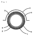
- the heat radiation section a be formed on the entire outer surface of the semicylindrical section that is positioned on the side opposite to a main body 4 of a vehicle.
- heat radiation section a When the heat radiation section a is formed as described above, heat can be effectively released to the side opposite to the main body 4 when the pipe cover 3 is provided around the outer periphery of a pipe 5, and thermal deterioration in the constituent member or the like provided on the side of the main body 4 can be advantageously suppressed.
- the area of the heat radiation section included in the pipe cover according to one embodiment of the invention is preferably 20 to 80%, more preferably 30 to 70%, and still more preferably 40 to 60%, based on the total outer surface area of the surface member.
- the emissivity of the heat radiation section included in the pipe cover according to one embodiment of the invention at a wavelength of 2 to 15 ⁇ m is preferably 60 to 99%, more preferably 70 to 99%, and still more preferably 80 to 99%.
- heat can be advantageously dissipated through the heat radiation section from a fluid that circulates through the pipe.
- emissivity (%) refers to a value calculated by the following expression using the reflectance (%) and the transmittance (%) measured when applying electromagnetic waves having a wavelength of 2 to 15 ⁇ m to the sample (pipe) at a temperature of 25°C.
- Emissivity % 100 - reflectance - transmittance
- Reflectance % reflected light intensity / incident light intensity ⁇
- Transmittance % transmitted light intensity / incident light intensity ⁇ 100
- the reflectance and the transmittance refer to values measured using a high-temperature reflectance/transmittance measurement device.
- FIG. 2 schematically illustrates an example of the high-temperature reflectance/transmittance measurement device.
- a high-temperature reflectance/transmittance measurement device is configured so that incident light 71 (wavelength: 2 to 15 ⁇ m) applied from a Fourier transform infrared spectrophotometer ("FT-LR6100” manufactured by JASCO Corporation) 6 is reflected by mirrors 8, introduced into a sample chamber, and applied to a sample 10 mounted at the center of a rotary stage 9.
- the sample 10 is heated by halogen heaters 11 ("UL-SH-V500" manufactured by Ushio, Inc.) in a state in which the sample 10 is mounted on a holder h that is provided at the center of the rotary stage 9.
- the intensity of reflected light from the sample 10 or the intensity of transmitted light 72 is detected by a detector 12 that is provided to an arm section of the rotary stage 9 that rotates around the mounting section for the sample 10, and rotates around the sample 10.
- FIG. 3 is a cross-sectional view illustrating an example of the structure of the heating section of the high-temperature reflectance/transmittance measurement device X.
- the halogen heaters 11 are respectively provided on the front side and the back side of the sample 10.
- the halogen heaters 11 are provided above the sample 10 to form an angle relative to the sample 10 so that the halogen heaters 11 do not block the optical path when the detector 12 detects reflected light or transmitted light from the sample 10.
- the halogen heaters 11 are rotated together with the sample 10 so that the surface temperature of the sample 10 can be always maintained at a constant temperature. Cooling water 13 is introduced (circulated) from the outside into the bottom of the rotary stage 9 (on which the sample 10 is mounted) and the halogen heaters 11 to effect cooling.
- the pipe cover according to one embodiment of the invention preferably has a configuration in which the surface member is formed of a metal thin film, and the heat radiation-suppressing section is formed of a coating film of an antioxidant that suppresses oxidation of the metal that forms the surface member.
- a silicon alkoxide such as ethyl silicate, other metal alkoxides, and the like are preferable as the antioxidant.
- the coating film of the antioxidant may be formed by applying the antioxidant using a spray, a brush, or the like, reacting the applied antioxidant for a given time, and drying the resulting product.
- the heat radiation-suppressing section included in the pipe cover according to one embodiment of the invention may be formed of a thin film that includes aluminum, gold, or platinum. It is preferable that the heat radiation-suppressing section be formed of an aluminum thin film.
- the thin film may be provided by forming a film of a material corresponding to the desired thin film on the outer surface of the surface member using a thermal spraying method, a CVD method, or a PVD method.
- the material for forming the heat radiation-suppressing section included in the pipe cover according to one embodiment of the invention is the same as the material for forming the surface member, the area of the outer surface of the surface member on which the heat radiation section is not provided may be used directly as the heat radiation-suppressing section.
- the thickness of the heat radiation-suppressing section is preferably 0.001 to 100 ⁇ m, more preferably 0.001 to 50 ⁇ m, and still more preferably 0.001 to 10 ⁇ m.
- the thickness of the heat radiation-suppressing section included in the pipe cover according to one embodiment of the invention is within the above range, radiation of heat toward the member positioned opposite to the pipe can be easily suppressed within the desired range.
- thickness used herein in connection with the heat radiation-suppressing section refers to a value measured using an X-ray photoelectron spectroscope (XPS).
- XPS X-ray photoelectron spectroscope
- the emissivity of the heat radiation-suppressing section included in the pipe cover according to one embodiment of the invention at a wavelength of 2 to 15 ⁇ m is preferably 0.1 to 40%, more preferably 0.1 to 35%, and still more preferably 0.1 to 30%.
- the thickness of the heat radiation-suppressing section included in the pipe cover according to one embodiment of the invention is within the above range, radiation of heat toward the member positioned opposite to the pipe that is covered with the pipe cover can be advantageously suppressed.
- the position and the area of the heat radiation-suppressing section provided on the outer surface of the surface member included in the pipe cover according to one embodiment of the invention may be appropriately determined depending on the installation position of the pipe that is covered with the pipe cover, the shape of the member that is opposite to the pipe, the desired heat radiation-suppressing capability of the heat radiation-suppressing section, and the like.
- the heat radiation-suppressing section is preferably formed over the entire outer surface of the surface member that is positioned on the side of the main body of a vehicle when the pipe cover is installed in the vehicle.
- the heat radiation-suppressing section is preferably formed over the entire outer surface of the semicylindrical section that is positioned on the side of the main body of a vehicle when the pipe cover is installed in the vehicle.
- the heat radiation-suppressing section b be formed on the entire outer surface of the semicylindrical section that is positioned on the side of the main body 4 of a vehicle.
- the heat radiation-suppressing section b When the heat radiation-suppressing section b is formed as described above, radiation of heat toward the main body 4 can be effectively suppressed when the pipe cover 3 is provided around the outer periphery of the pipe 5, and thermal deterioration in the constituent member of the main body 4 can be advantageously suppressed.
- the area of the heat radiation-suppressing section included in the pipe cover according to one embodiment of the invention is preferably 20 to 80%, more preferably 30 to 70%, and still more preferably 40 to 60%, based on the total outer surface area of the surface member formed of the tubular heat insulator.
- the pipe cover according to one embodiment of the invention be configured so that the heat radiation section and the heat radiation-suppressing section are provided over the entire surface of the surface member so as to be adjacent to each other.
- the area ratio (area of heat radiation section: area of heat radiation-suppressing section) of the heat radiation section to the heat radiation-suppressing section is preferably 20:80 to 80:20, more preferably 30:70 to 70:30, and still more preferably 40:60 to 60:40.
- the thermal resistance (per 1 m in the circumferential direction) of the surface member included in the pipe cover according to one embodiment of the invention is preferably 10 K/W or less, more preferably 4 to 10 K/W, and still more preferably 4 K/W or less.
- the thermal resistance is an index that indicates ease of heat flow.
- the length d in the heat flow direction may be measured using calipers.
- the thermal conductivity ⁇ may be measured using a heat flow meter or the like.
- the heat flow area S may be measured using a metal measure.
- the pipe cover according to one embodiment of the invention may particularly preferably be used when a member (member that is affected by heat) that is positioned opposite to the pipe cover when the pipe cover is provided around a pipe is a member that is formed of a material that exhibits low heat resistance (e.g., resin member or rubber member (e.g., bumper)), or a member to which a material that exhibits low heat resistance (e.g., resin or grease) is applied, for example.
- a member member that is affected by heat
- a member that is affected by heat is positioned opposite to the pipe cover when the pipe cover is provided around a pipe
- a member that is formed of a material that exhibits low heat resistance e.g., resin member or rubber member (e.g., bumper)
- a member to which a material that exhibits low heat resistance e.g., resin or grease
- the pipe cover according to one embodiment of the invention may suitably be used for pipes of various vehicles and a semiconductor production system.
- the pipe cover according to one embodiment of the invention may particularly suitably be used as a pipe cover for an automotive exhaust gas discharge pipe.
- Examples of the automotive exhaust gas discharge pipe include exhaust pipes that are connected to an exhaust gas unit that is provided under the floor of a vehicle, and exhaust pipes incorporated in such an exhaust gas unit (e.g., exhaust manifold, catalytic converter provided directly below an exhaust manifold, front tube, underfloor catalytic converter, center muffler, and main muffler).
- exhaust pipes e.g., exhaust manifold, catalytic converter provided directly below an exhaust manifold, front tube, underfloor catalytic converter, center muffler, and main muffler).
- the heat radiation section and the heat radiation-suppressing section may be appropriately provided corresponding to the heat-resistant temperature of a member positioned opposite to the pipe cover. It is preferable to provide the heat radiation section and the heat radiation-suppressing section so that the temperature of a member positioned opposite to the pipe cover is 160°C or less.
- the pipe cover according to one embodiment of the invention is provided around a pipe so that the heat radiation section faces a side where it is desired to promote heat release, and the heat radiation-suppressing section faces a side where it is desired to suppress heat release.
- the distance between the pipe cover and a member (member that is affected by heat) positioned opposite to the pipe cover is preferably 1 to 100 mm, more preferably 10 to 75 mm, and still more preferably 20 to 50 mm.
- the pipe cover according to one embodiment of the invention includes the base that is formed of the tubular heat insulator, and the surface member, the heat radiation section, and the heat radiation-suppressing section are provided on the outer surface of the base, it is possible to provide a novel pipe cover that can suppress thermal deterioration in an opposing member through the base and the heat radiation-suppressing section, and can advantageously suppress an increase in temperature inside the pipe by releasing heat from the heat radiation section through the base, even when a high-temperature fluid circulates through the pipe.
- a pipe structure according to one embodiment of the invention is described below.
- the pipe structure according to one embodiment of the invention includes a pipe, and the pipe cover according to one embodiment of the invention that covers the outer periphery of the pipe.
- pipe refers to a tubular product (article) through which a fluid circulates. It is preferable to appropriately select a pipe that is formed of a material corresponding to the temperature and the like of a fluid that circulates through the pipe, and has a structure that does not show deterioration, leakage, and the like.
- a pipe that exhibits heat resistance.
- the pipe include a metal pipe, a resin pipe formed of a heat-resistant resin, and the like. It is preferable to use a metal pipe.
- a stainless steel pipe (SS pipe) is used as the metal pipe from the viewpoint of heat resistance and corrosion resistance.
- SS pipe is used as the metal pipe from the viewpoint of heat resistance and corrosion resistance.
- the temperature of a fluid that circulates through the pipe is less than 500°C, it is preferable to use an aluminum pipe as the pipe.
- the temperature of a fluid that circulates through the pipe is 600 to 900°C, it is preferable to use an SS pipe as the pipe.
- the cross-sectional shape of the pipe is not particularly limited.
- the cross-sectional shape of the pipe may be circular, elliptical, or the like.
- the average thickness of the pipe is preferably 0.5 to 3.0 mm, more preferably 0.8 to 2.0 mm, and still more preferably 1.0 to 1.5 mm.
- average thickness used herein in connection with the pipe (tubular base) refers to the arithmetic mean value of the thicknesses of the pipe measured at three points using calipers.
- the outer diameter of the pipe is preferably 20 to 110 mm, more preferably 30 to 80 mm, and still more preferably 35 to 65 mm.
- outer diameter used herein in connection with the pipe (tubular base) refers to a value measured using calipers.
- the temperature inside the pipe and the temperature outside the pipe can be easily controlled with a preferable range.
- the pipe structure according to one embodiment of the invention is provided (covered) with the pipe cover that includes the base that is formed of the tubular heat insulator, and is configured so that the surface member, the heat radiation section, and the heat radiation-suppressing section are provided on the outer surface of the base, it is possible to provide a novel structure that can suppress thermal deterioration in an opposing member through the base and the heat radiation-suppressing section, and can advantageously suppress an increase in temperature inside the pipe by releasing heat from the heat radiation section through the base, even when a high-temperature fluid circulates through the pipe.
- a vehicle according to one embodiment of the invention is described below.
- the vehicle according to one embodiment of the invention includes the pipe structure according to one embodiment of the invention.
- the vehicle according to one embodiment of the invention preferably includes the pipe structure according to one embodiment of the invention as an automotive exhaust gas discharge pipe structure.
- the vehicle according to one embodiment of the invention can particularly advantageously suppress thermal deterioration when the vehicle includes a member that is formed of a material that exhibits low heat resistance (e.g., resin member or rubber member (e.g., bumper)), or a member to which a material that exhibits low heat resistance (e.g., resin or grease) is applied, as a member (member that is affected by heat) that is positioned opposite to the pipe.
- a member that is formed of a material that exhibits low heat resistance e.g., resin member or rubber member (e.g., bumper)
- a member to which a material that exhibits low heat resistance e.g., resin or grease
- the pipe structure according to one embodiment of the invention may be an exhaust pipe structure that is connected to an exhaust gas unit that is provided under the floor of a vehicle, or an exhaust pipe structure that is incorporated in such an exhaust gas unit (e.g., exhaust manifold, catalytic converter provided directly below an exhaust manifold, front tube, underfloor catalytic converter, center muffler, or main muffler).
- an exhaust gas unit e.g., exhaust manifold, catalytic converter provided directly below an exhaust manifold, front tube, underfloor catalytic converter, center muffler, or main muffler.
- the pipe structure is disposed in the vehicle according to one embodiment of the invention so that the heat radiation section faces a side where it is desired to promote release of heat from the pipe, and the heat radiation-suppressing section faces a side where it is desired to suppress release of heat from the pipe.
- the vehicle according to one embodiment of the invention preferably has a configuration in which the distance between the pipe structure and a member (member that is affected by heat) positioned opposite to the pipe structure is 1 to 100 mm, more preferably 10 to 75 mm, and still more preferably 20 to 50 mm.
- vehicle examples include an automobile, a two-wheel vehicle, a farm vehicle, and the like.
- the vehicle according to one embodiment of the invention includes the pipe structure having a configuration in which the outer periphery of the pipe is covered with the pipe cover that includes the base that is formed of the tubular heat insulator, and is configured so that the surface member, the heat radiation section, and the heat radiation-suppressing section are provided on the outer surface of the base, it is possible to provide a novel vehicle that can suppress thermal deterioration in an opposing member through the base and the heat radiation-suppressing section, and can control the temperature inside the pipe within a given range by releasing heat from the heat radiation section through the base, even when a high-temperature fluid circulates through the pipe.
- An SS (stainless steel) pipe (length: 500 mm, outer diameter: 48.6 mm, thickness: 1 mm) was used as the pipe 5 (see FIG. 1 ).
- a halved pipe-shaped product (inner diameter: 48.6 mm) was produced by bonding an aluminum surface member 2 (thickness: 0.3 mm) to the entire surface of a glass fiber mat-shaped product (length: 500 mm, thickness: 10 mm) ("Super Wool Mat” manufactured by Yazawa-Sangyo Co., Ltd., density: 110 kg/m 3 ) using an epoxy-based adhesive.
- the entire outer surface of the halved pipe-shaped product was divided into two semicylindrical sections.
- the outer surface of the aluminum surface member 2 was used directly as the heat radiation-suppressing section b (upper semicylindrical section), and an aluminum oxide thin film (thickness: 80 ⁇ m) was formed over the entire outer surface of the lower semicylindrical section using a thermal spraying method to form the heat radiation section a to obtain the pipe cover 3.
- the pipe cover 3 had a configuration in which the heat radiation section a and the heat radiation-suppressing section b were adjacent to each other, the area of the heat radiation section a was 50 % of the total outer surface area of the pipe cover, and the area of the heat radiation-suppressing section b was 50 % of the total outer surface area of the pipe cover.
- the emissivity ⁇ 1 of the heat radiation section a at a wavelength of 2 to 15 ⁇ m was 80%, and the emissivity ⁇ 2 of the heat radiation-suppressing section b at a wavelength of 2 to 15 ⁇ m was 1%.
- the thermal resistance (per 1 m in the circumferential direction) of the outer surface (surface member 2) of the pipe cover 3 was 3.59 K/W.
- the pipe cover 3 was wound around the outer periphery of the pipe 5 to prepare a pipe structure in which the outer periphery of the pipe 5 was covered with the pipe cover 3.
- a polyimide (PI) resin member (length: 500 mm, equivalent diameter of semicylindrical section (R section): 88.6 mm, thickness: 1 mm, heat-resistant temperature: 350°C) was provided as a resin member 4 that forms the main body of a vehicle (see FIG. 1 ). Since the PI resin is a resin that exhibits excellent heat resistance, the PI resin can suitably be used as an alternative to polypropylene and a nitrile-butadiene rubber (NBR) that are normally used as a heat-resistant resin for forming a member that forms the main body of a vehicle.
- NBR nitrile-butadiene rubber
- the emissivity s 3 of the resin member 4 at a wavelength of 2 to 15 ⁇ m was 95%.
- the pipe structure was disposed so that the heat radiation-suppressing section b faced the semicylindrical section (R section) of the resin member 4 at an interval of 10 mm (see FIG 1 ), and air (750°C) was supplied to the inner space of the pipe 5 at room temperature (20°C) for 30 minutes at a supply rate of 0.01 kg/sec.
- the average surface temperature of the heat radiation section a that forms the pipe cover 3 when air was circulated was 195°C
- the average surface temperature of the heat radiation-suppressing section b that forms the pipe cover 3 when air was circulated was 355°C.
- the average surface temperature and the maximum surface temperature of the resin member 4 when air was circulated were respectively 122°C and 152°C.
- An SS (stainless steel) pipe (length: 500 mm, outer diameter: 48.6 mm, thickness: 1 mm) was used instead of the pipe structure used in Example 1.
- the SS pipe was disposed to face the resin member 4 (see Example 1) at an interval of 20 mm.
- Air (750°C) was then supplied to the inner space of the SS pipe at room temperature (20°C) for 30 minutes at a supply rate of 0.01 kg/sec.
- the average surface temperature of the lower side (i.e., the side opposite to the resin member 4) of the SS pipe when air was circulated was 411°C
- the average surface temperature of the upper side (i.e., the side facing the resin member 4) of the SS pipe when air was circulated was 441°C.
- the average surface temperature and the maximum surface temperature of the resin member 4 when air was circulated were respectively 204°C and 249°C.
- the pipe cover 3 used in Example 1 had a configuration in which the heat radiation section a and the heat radiation-suppressing section b were provided on the outer surface of the pipe 5 through the surface member 2, and the emissivity of the heat radiation section a at a wavelength of 2 to 15 ⁇ m was higher than the emissivity of the heat radiation-suppressing section b at a wavelength of 2 to 15 ⁇ m, the average surface temperature of the resin member 4 could be suppressed to 122°C, and the maximum surface temperature of the resin member 4 could be suppressed to 152°C.
- thermal deterioration in the resin member 4 that forms the main body of a vehicle can be suppressed when using the pipe structure in which the pipe 5 is covered with the pipe cover 3 as an automotive exhaust gas discharge pipe structure (e.g., muffler).
- an automotive exhaust gas discharge pipe structure e.g., muffler
- the pipe cover since the pipe cover includes the base that is formed of the tubular heat insulator, and the surface member, wherein the heat radiation section, and the heat radiation-suppressing section are provided on the outer surface of the base, it is possible to provide a novel pipe cover that can suppress thermal deterioration in a member positioned opposite to the pipe by means of the base and the heat radiation-suppressing section, and can advantageously suppress an increase in temperature inside the pipe by releasing heat from the heat radiation section through the base, even when a high-temperature fluid circulates through the pipe. According to the embodiments of the invention, it is also possible to provide a pipe structure that includes the pipe cover and a pipe, and a vehicle that includes the pipe structure.
Landscapes
- Engineering & Computer Science (AREA)
- General Engineering & Computer Science (AREA)
- Mechanical Engineering (AREA)
- Chemical & Material Sciences (AREA)
- Combustion & Propulsion (AREA)
- Exhaust Silencers (AREA)
- Thermal Insulation (AREA)
Abstract
Description
- The invention relates to a pipe cover, a pipe structure, and a vehicle.
- A combustion gas (exhaust gas) discharged from an automotive engine is discharged to the outside through an exhaust manifold, a catalytic converter provided directly below the exhaust manifold, a front tube, an underfloor catalytic converter, a center muffler, a main muffler, and the like (see Patent Document 1 (
JP-A-11-81976 - An automotive engine is designed so that the amount of fuel is increased in a high-load/high-revolution region. In this case, a high-temperature exhaust gas flows through the main muffler and the like, and a large amount of heat is released toward the main body of the vehicle positioned opposite to the main muffler and the like. This accelerates thermal deterioration in a resin member or a rubber member (e.g., bumper) that forms the main body, grease applied to a member that forms the main body, or the like.
- Therefore, an automotive exhaust pipe (automotive exhaust gas discharge pipe) has been desired that can suppress thermal deterioration in the main body of a vehicle when the automotive engine is operated at high speed.
- Patent Document 1:
JP-A-11-81976 - An object of the invention is to provide a novel pipe cover that can suppress thermal deterioration in a member that is positioned opposite to the pipe, and can advantageously suppress an increase in temperature inside the pipe, even when a high-temperature fluid circulates through the pipe, a pipe structure that includes the pipe cover and a pipe, and a vehicle that includes the pipe structure.
- The inventors of the invention conducted extensive studies in order to achieve the above object. As a result, the inventors found that the above object can be achieved by a pipe cover that includes a base that is formed of a tubular heat insulator, and a surface member that covers the outer surface of the base, wherein a heat radiation section and a heat radiation-suppressing section are provided on the outer surface of the surface member, and the emissivity of the heat radiation section at a wavelength of 2 to 15 µm is higher than the emissivity of the heat radiation-suppressing section at a wavelength of 2 to 15 µm. This finding has led to the completion of the invention.
- Specifically, several aspects of the invention provide:
- (1) A pipe cover that is used to cover the outer periphery of a pipe, the pipe cover including a base that is formed of a tubular heat insulator, and a surface member that covers the outer surface of the base, a heat radiation section and a heat radiation-suppressing section being provided on the outer surface of the surface member, and the emissivity of the heat radiation section at a wavelength of 2 to 15 µm being higher than the emissivity of the heat radiation-suppressing section at a wavelength of 2 to 15 µm;
- (2) The pipe cover according to (1), wherein the surface member is formed of a metal thin film, and the heat radiation section is formed of a ceramic thin film or a carbon thin film;
- (3) The pipe cover according to (1), wherein the surface member is formed of a metal thin film, and the heat radiation section is formed of an oxide film of a metal that forms the surface member;
- (4) The pipe cover according to any one of (1) to (3), wherein the emissivity of the heat radiation section at a wavelength of 2 to 15 µm is 60 to 99%;
- (5) The pipe cover according to (1), wherein the surface member is formed of a metal thin film, and the heat radiation-suppressing section is formed of a coating film of an antioxidant that suppresses oxidation of the metal that forms the surface member;
- (6) The pipe cover according to (1) or (5), wherein the emissivity of the heat radiation-suppressing section at a wavelength of 2 to 15 µm is 0.1 to 40%;
- (7) A pipe structure including a pipe, and the pipe cover according to (1) that covers the outer periphery of the pipe;
- (8) A vehicle including the pipe structure according to (7); and
- (9) The vehicle according to (8), wherein the pipe structure is an automotive exhaust gas discharge pipe structure.
- Since the pipe cover according to one aspect of the invention includes the base that is formed of the tubular heat insulator, and the surface member, the heat radiation section, and the heat radiation-suppressing section are provided on the outer surface of the base, it is possible to provide a novel pipe cover that can suppress thermal deterioration in a member positioned opposite to the pipe by means of the base and the heat radiation-suppressing section, and can advantageously suppress an increase in temperature inside the pipe by releasing heat from the heat radiation section through the base, even when a high-temperature fluid circulates through the pipe. It is also possible to provide a pipe structure that includes the pipe cover and a pipe, and a vehicle that includes the pipe structure.
-
-
FIG 1 is a view illustrating an example of usage of a pipe cover according to one embodiment of the invention. -
FIG. 2 is a schematic view illustrating a high-temperature reflectance/transmittance measurement device used to measure emissivity. -
FIG 3 is a cross-sectional view illustrating a heating section of a high-temperature reflectance/transmittance measurement device used to measure emissivity. - A pipe cover according to one embodiment of the invention is described below.
- The pipe cover according to one embodiment of the invention is used to cover the outer periphery of a pipe, and includes a base that is formed of a tubular heat insulator, and a surface member that covers the outer surface of the base, a heat radiation section and a heat radiation-suppressing section being provided on the outer surface of the surface member, and the emissivity of the heat radiation section at a wavelength of 2 to 15 µm being higher than the emissivity of the heat radiation-suppressing section at a wavelength of 2 to 15 µm.
- The pipe cover according to one embodiment of the invention includes the base that is formed of the tubular heat insulator.
- The heat insulator that forms the base included in the pipe cover according to one embodiment of the invention is preferably formed of an inorganic material.
- Specific examples of the tubular heat insulator include a heat insulator obtained by forming a mat-shaped product formed of inorganic fibers (e.g., glass fibers, ceramic fibers, or rock wool) (hereinafter referred to as "
heat insulator 1") in the shape of a tube. - The tubular heat insulator included in the pipe cover according to one embodiment of the invention may be a heat insulator obtained by forming a laminate in the shape of a tube, the laminate having a configuration in which at least one inorganic heat-resistant paper that is impregnated with an inorganic binder, and at least one metal foil are stacked (hereinafter referred to as "
heat insulator 2"). - When the tubular heat insulator is formed of the
heat insulator 2, colloidal silica, colloidal alumina, and the like are preferable as the inorganic binder. - The primary particle size of the inorganic binder is normally 10 to 20 nm. When using colloidal silica as the inorganic binder, it is preferable that the colloidal silica have a silicic anhydride content of 10 to 40 wt%, and more preferably about 30 wt%, from the viewpoint of storage stability.
- The heat resistance of the
heat insulator 2 can be easily improved by utilizing the inorganic heat-resistant paper that is impregnated with the inorganic binder. - When the tubular heat insulator included in the pipe cover according to one embodiment of the invention is formed of the
heat insulator 2, it is preferable that the inorganic heat-resistant paper that is impregnated with the inorganic binder have an inorganic fiber content of 70 wt% or more. Ceramic-based fibers that exhibit heat resistance are preferable as the inorganic fibers. Specific examples of the inorganic fibers include rock wool, alumina fibers, and the like. - When the tubular heat insulator included in the pipe cover according to one embodiment of the invention is formed of the
heat insulator 2, the tubular heat insulator may include an inorganic filler, a small amount of organic fibers, and an organic binder. - Examples of the inorganic filler include aluminum hydroxide, talc, calcium carbonate, and the like.
- It is preferable that the
heat insulator 2 have a configuration in which the inorganic binder adheres to the inorganic heat-resistant paper in an amount of 30 to 200 parts by weight based on 100 parts by weight of the inorganic heat-resistant paper. - If the inorganic binder adheres to the inorganic heat-resistant paper in an amount of less than 30 parts by weight based on 100 parts by weight of the inorganic heat-resistant paper, the strength retention ratio may decrease, and sufficient heat resistance may not be obtained. If the inorganic binder adheres to the inorganic heat-resistant paper in an amount of more than 200 parts by weight based on 100 parts by weight of the inorganic heat-resistant paper, the secondary particles of colloidal silica that adhere to the inorganic heat-resistant paper may be easily removed.
- The
heat insulator 2 may be produced by impregnating the inorganic heat-resistant paper with an inorganic impregnation solution such as a colloidal silica solution, and drying the inorganic heat-resistant paper. - When the tubular heat insulator included in the pipe cover according to one embodiment of the invention is formed of the
heat insulator 2, the metal foil may be an aluminum foil, a stainless steel foil, a copper foil, or the like, and is preferably an aluminum foil. - The thickness of the metal foil is preferably 0.02 to 0.5 mm, more preferably 0.05 to 0.45 mm, and still more preferably 0.08 to 0.4 mm.
- Note that the term "thickness" used herein in connection with the metal foil refers to the arithmetic mean value of the thicknesses of the metal foil measured at five points using calipers.
- The
heat insulator 2 may include an adhesive layer that is formed between the layers of the laminate obtained by stacking the inorganic heat-resistant paper and the metal foil in order to improve adhesion. The adhesive layer may be formed by applying a heat seal-type adhesive (e.g., polyester-based adhesive, vinyl chloride-based adhesive, or ethylene copolymer-based adhesive), and drying the applied adhesive. The adhesive layer is preferably formed by applying an aqueous ethylene copolymer-based adhesive, and drying the applied adhesive taking account of environmental issues. - The
heat insulator 2 may be formed by stacking the inorganic heat-resistant paper and the metal foil while optionally bonding the inorganic heat-resistant paper and the metal foil using the adhesive. The tubular heat insulator is obtained by forming the resultingheat insulator 2 in the shape of a tube. - The tubular heat insulator may be obtained by spirally winding the inorganic heat-resistant paper and the metal foil around a mandrel (core member) in a state in which the inorganic heat-resistant paper and the metal foil are stacked while optionally bonding the inorganic heat-resistant paper and the metal foil using the adhesive. In this case, the resulting product may be pleated by passing the product through a die to provide the product with flexibility.
- The
heat insulator 2 may have a two-layer configuration in which one metal foil and one inorganic heat-resistant paper are stacked, or may have a configuration formed by three or more layers in which the metal foil and/or the inorganic heat-resistant paper are/is further stacked. - The tubular heat insulator included in the pipe cover according to one embodiment of the invention preferably has a cross-sectional shape corresponding to the cross-sectional shape of the pipe that is covered with the pipe cover. It is preferable that the tubular heat insulator have a circular or elliptical cross-sectional shape.
- For example, when the pipe that is covered with the pipe cover according to one embodiment of the invention has a circular cross-sectional shape, it is preferable that the inner diameter of the tubular heat insulator be the same as the outer diameter of the pipe that is covered with the pipe cover.
- The thickness of the heat insulator that forms the tubular heat insulator included in the pipe cover according to one embodiment of the invention is preferably 1 to 30 mm, more preferably 3 to 25 mm, and still more preferably 5 to 20 mm.
- Note that the term "thickness" used herein in connection with the heat insulator refers to the arithmetic mean value of the thicknesses of the heat insulator measured at five points using a Peacock dial thickness gauge (manufactured by Ozaki Mfg. Co., Ltd.).
- The density of the heat insulator that forms the tubular heat insulator included in the pipe cover according to one embodiment of the invention is preferably 50 to 250 g/cm3, more preferably 75 to 200 g/cm3, and still more preferably 100 to 180 g/cm3.
- When the thickness and the density of the heat insulator that forms the tubular heat insulator included in the pipe cover according to one embodiment of the invention are within the above ranges, it is possible to easily suppress thermal deterioration in the member that is opposite to the pipe, and easily control the temperature inside the pipe within a given range when the pipe cover is installed together with the pipe.
- Since the pipe cover according to one embodiment of the invention is used to cover the outer periphery of the pipe, it is preferable that the tubular heat insulator be split in advance. Specifically, it is preferable that the tubular heat insulator be formed by attaching two semicylindrical members in the shape of a tube, and securing (bonding) the semicylindrical members using the surface member (described below).
- The pipe cover according to one embodiment of the invention includes the surface member that is provided on the outer surface of the base that is formed of the tubular heat insulator.
- The surface member is preferably formed of a metal thin film. Examples of the metal thin film include an aluminum thin film, a stainless steel thin film, and the like.
- The thickness of the surface member is preferably 0.05 to 3 mm, more preferably 0.1 to 2 mm, and still more preferably 0.2 to 1 mm.
- Note that the term "thickness" used herein in connection with the surface member refers to the arithmetic mean value of the thicknesses of the surface member measured at five points using calipers.
- The surface member included in the pipe cover according to one embodiment of the invention may be integrated with the base that is formed of the tubular heat insulator by applying a heat seal-type adhesive (e.g., polyester-based adhesive, vinyl chloride-based adhesive, or ethylene copolymer-based adhesive) to the base, and bonding the surface member to the base. It is preferable to use an aqueous ethylene copolymer-based adhesive taking account of environmental issues.
- The heat radiation section and the heat radiation-suppressing section are provided on the outer surface of the surface member included in the pipe cover according to one embodiment of the invention.
- The term "heat radiation section" used herein refers to a member of which the emissivity is controlled to be higher than those of the base and the heat radiation-suppressing section, and the term "heat radiation-suppressing section" used herein refers to a member of which the emissivity is controlled to be lower than those of the base and the heat radiation section.
- It is preferable that the heat radiation section and the heat radiation-suppressing section included in the pipe cover according to one embodiment of the invention be formed in the shape of a film.
- The emissivity of the heat radiation section and the heat radiation-suppressing section included in the pipe cover according to one embodiment of the invention may be controlled by appropriately selecting materials for forming the heat radiation section and the heat radiation-suppressing section, or adjusting the surface flatness of the heat radiation section and the heat radiation-suppressing section.
- It is preferable that the heat radiation section included in the pipe cover according to one embodiment of the invention be formed of a ceramic thin film or a carbon thin film.
- Examples of the ceramic thin film include a thin film formed of a material that includes a ceramic (e.g., alumina, silicon carbide, or titanium oxide). The ceramic thin film is preferably a thin film formed of a material that includes alumina.
- Examples of the carbon thin film include a diamond-like carbon (DLC) thin film.
- When the heat radiation section included in the pipe cover according to one embodiment of the invention is formed of a ceramic thin film, the ceramic thin film may be provided by forming a film of a ceramic material corresponding to the desired ceramic thin film on the outer surface of the surface member using a thermal spraying method, a chemical vapor deposition (CVD) method, or a physical vapor deposition (PVD) method.
- When the heat radiation section included in the pipe cover according to one embodiment of the invention is formed of a ceramic thin film, the ceramic thin film may be formed by applying a coating liquid for forming the desired ceramic thin film to the surface of the tubular base, and drying the applied coating liquid.
- The coating liquid may include 100 parts by mass of a ceramic powder, 40 to 200 parts by mass (on solid basis) of an inorganic binder, 0.1 to 1.0 part by mass of an organic binder, 0.1 to 1.0 part by mass of a thickener, and 60 to 130 parts by mass of water (solvent), for example.
- The inorganic binder may be one or more materials selected from borosilicate glass, colloidal silica, colloidal alumina, and the like. The organic binder may be one or more materials selected from an acrylic-based binder, cationic starch, and the like. The thickener may be one or more materials selected from hi Metolose, bentonite, kaolin, and the like.
- The coating liquid may be applied by spraying, brushing, or the like.
- When the heat radiation section included in the pipe cover according to one embodiment of the invention is formed of a carbon thin film, the carbon thin film may be provided by forming a film of a material for forming the desired thin film on the surface of the tubular base using a CVD method or a PVD method.
- The pipe cover according to one embodiment of the invention may have a configuration in which the surface member is formed of a metal thin film, and the heat radiation section is formed of an oxide film of the metal that forms the surface member.
- For example, when the surface member is formed of an aluminum thin film, the heat radiation section is preferably formed of an aluminum oxide film. When the surface member is formed of a stainless steel thin film, the heat radiation section is preferably formed of a stainless steel oxide film.
- The oxide film of the metal that forms the surface member may be formed by subjecting the metal thin film that forms the surface member to an alumite treatment, or heating the metal thin film for a desired time using a burner or the like.
- When the heat radiation section included in the pipe cover according to one embodiment of the invention is formed of a ceramic thin film, a carbon thin film, or an oxide film of a metal that forms the surface member, the thickness of the heat radiation section is preferably 0.1 to 500 µm, more preferably 0.1 to 200 µm, and still more preferably 0.1 to 100 µm.
- When the thickness of the heat radiation section included in the pipe cover according to one embodiment of the invention is within the above range, the temperature inside the pipe can be advantageously suppressed.
- The term "thickness" used herein in connection with the heat radiation section refers to a value measured when observing the cross section of the pipe using a scanning electron microscope (SEM).
- The emissivity of the heat radiation section included in the pipe cover according to one embodiment of the invention may be increased as compared with that of the heat radiation-suppressing section by forming elevations and depressions on the surface of the heat radiation section.
- It is preferable to form such elevations and depressions by subjecting the surface of the surface member to a blasting treatment or the like.
- Examples of the blasting technique include an air blasting technique that applies blasting media from a nozzle using compressed air utilizing an air compressor or the like, a shot blasting technique that applies blasting media using the centrifugal force of an impeller made of an abrasion-resistant alloy and driven using a motor, a wet blasting technique that applies blasting media mixed into liquid using a submersible pump or compressed air, and the like.
- When subjecting the surface of the surface member to a blasting treatment, the depth of elevations and depressions formed on the surface of the surface member can be controlled by appropriately selecting (adjusting) the type of the blasting media, the average particle size of the blasting media, the blasting media application pressure, the blasting media application time, and the like.
- Examples of the blasting media used for the blasting treatment include silicon carbide, alumina, and the like. The average particle size of the blasting media is preferably from 3 to 53 µm.
- The term "average particle size" used herein in connection with the blasting media refers to the particle size at 50% (D50) in the cumulative volume particle size distribution measured using a laser diffraction particle size analyzer.
- The depth Rz of elevations and depressions formed on the surface of the surface member is preferably 1 to 50 µm, more preferably 2 to 40 µm, and still more preferably 3 to 25 µm.
- The term "depth" used herein in connection with elevations and depressions formed on the surface of the surface member refers to a value measured using a stylus-type surface profile analyzer (surface roughness tester).
- The pipe cover according to one embodiment of the invention may have a configuration in which a ceramic thin film, a carbon thin film, or an oxide film of a metal that forms the surface member is formed on the surface of the surface member that has been subjected to the blasting treatment. Specific examples of the ceramic thin film, the carbon thin film, or the oxide film include those mentioned above, and the ceramic thin film, the carbon thin film, or the oxide film may be formed by the above method.
- The position and the area of the heat radiation section provided on the outer surface of the surface member included in the pipe cover according to one embodiment of the invention may be appropriately determined depending on the installation position of the pipe that is covered with the pipe cover according to one embodiment of the invention, the shape of the member that is opposite to the pipe, the desired heat radiation capability of the pipe cover, and the like.
- When using the pipe cover according to one embodiment of the invention as a pipe cover that is used to cover an automotive exhaust gas discharge pipe, the heat radiation section is preferably formed over the entire outer surface of the surface member that is positioned opposite to the main body of a vehicle when the pipe cover is installed in the vehicle. For example, when the outer surface of the surface member is divided into two semicylindrical sections, the heat radiation section is preferably formed over the entire outer surface of the semicylindrical section that is positioned opposite to the main body of a vehicle when the pipe cover is installed in the vehicle. As illustrated in
FIG 1 (cross-sectional view), when the outer surface of thesurface member 2 provided on the surface of thebase 1 formed of the tubular heat insulator is divided into two semicylindrical sections, and a heat radiation section a and a heat radiation-suppressing section b are respectively provided on the two semicylindrical sections to obtain apipe cover 3, it is preferable that the heat radiation section a be formed on the entire outer surface of the semicylindrical section that is positioned on the side opposite to amain body 4 of a vehicle. - When the heat radiation section a is formed as described above, heat can be effectively released to the side opposite to the
main body 4 when thepipe cover 3 is provided around the outer periphery of apipe 5, and thermal deterioration in the constituent member or the like provided on the side of themain body 4 can be advantageously suppressed. - The area of the heat radiation section included in the pipe cover according to one embodiment of the invention is preferably 20 to 80%, more preferably 30 to 70%, and still more preferably 40 to 60%, based on the total outer surface area of the surface member.
- The emissivity of the heat radiation section included in the pipe cover according to one embodiment of the invention at a wavelength of 2 to 15 µm is preferably 60 to 99%, more preferably 70 to 99%, and still more preferably 80 to 99%.
- When the emissivity of the heat radiation section included in the pipe cover according to one embodiment of the invention is within the above range, heat can be advantageously dissipated through the heat radiation section from a fluid that circulates through the pipe.
- The term "emissivity (%)" used herein refers to a value calculated by the following expression using the reflectance (%) and the transmittance (%) measured when applying electromagnetic waves having a wavelength of 2 to 15 µm to the sample (pipe) at a temperature of 25°C.


- Note that the reflectance and the transmittance refer to values measured using a high-temperature reflectance/transmittance measurement device.
-
FIG. 2 schematically illustrates an example of the high-temperature reflectance/transmittance measurement device. - A high-temperature reflectance/transmittance measurement device is configured so that incident light 71 (wavelength: 2 to 15 µm) applied from a Fourier transform infrared spectrophotometer ("FT-LR6100" manufactured by JASCO Corporation) 6 is reflected by
mirrors 8, introduced into a sample chamber, and applied to asample 10 mounted at the center of arotary stage 9. Thesample 10 is heated by halogen heaters 11 ("UL-SH-V500" manufactured by Ushio, Inc.) in a state in which thesample 10 is mounted on a holder h that is provided at the center of therotary stage 9. The intensity of reflected light from thesample 10 or the intensity of transmitted light 72 is detected by adetector 12 that is provided to an arm section of therotary stage 9 that rotates around the mounting section for thesample 10, and rotates around thesample 10. -
FIG. 3 is a cross-sectional view illustrating an example of the structure of the heating section of the high-temperature reflectance/transmittance measurement device X. - As illustrated in
FIG. 3 , thehalogen heaters 11 are respectively provided on the front side and the back side of thesample 10. Thehalogen heaters 11 are provided above thesample 10 to form an angle relative to thesample 10 so that thehalogen heaters 11 do not block the optical path when thedetector 12 detects reflected light or transmitted light from thesample 10. When measuring reflected light or transmitted light, thehalogen heaters 11 are rotated together with thesample 10 so that the surface temperature of thesample 10 can be always maintained at a constant temperature. Coolingwater 13 is introduced (circulated) from the outside into the bottom of the rotary stage 9 (on which thesample 10 is mounted) and thehalogen heaters 11 to effect cooling. - The pipe cover according to one embodiment of the invention preferably has a configuration in which the surface member is formed of a metal thin film, and the heat radiation-suppressing section is formed of a coating film of an antioxidant that suppresses oxidation of the metal that forms the surface member.
- A silicon alkoxide such as ethyl silicate, other metal alkoxides, and the like are preferable as the antioxidant.
- The coating film of the antioxidant may be formed by applying the antioxidant using a spray, a brush, or the like, reacting the applied antioxidant for a given time, and drying the resulting product.
- The heat radiation-suppressing section included in the pipe cover according to one embodiment of the invention may be formed of a thin film that includes aluminum, gold, or platinum. It is preferable that the heat radiation-suppressing section be formed of an aluminum thin film.
- When the heat radiation-suppressing section included in the pipe cover according to one embodiment of the invention is formed of a thin film that includes aluminum, gold, or platinum, the thin film may be provided by forming a film of a material corresponding to the desired thin film on the outer surface of the surface member using a thermal spraying method, a CVD method, or a PVD method.
- When the material for forming the heat radiation-suppressing section included in the pipe cover according to one embodiment of the invention is the same as the material for forming the surface member, the area of the outer surface of the surface member on which the heat radiation section is not provided may be used directly as the heat radiation-suppressing section.
- When the heat radiation-suppressing section included in the pipe cover according to one embodiment of the invention is formed on the outer surface of the surface member in the shape of a film using a thermal spraying method or the like, the thickness of the heat radiation-suppressing section is preferably 0.001 to 100 µm, more preferably 0.001 to 50 µm, and still more preferably 0.001 to 10 µm.
- When the thickness of the heat radiation-suppressing section included in the pipe cover according to one embodiment of the invention is within the above range, radiation of heat toward the member positioned opposite to the pipe can be easily suppressed within the desired range.
- The term "thickness" used herein in connection with the heat radiation-suppressing section refers to a value measured using an X-ray photoelectron spectroscope (XPS).
- The emissivity of the heat radiation-suppressing section included in the pipe cover according to one embodiment of the invention at a wavelength of 2 to 15 µm is preferably 0.1 to 40%, more preferably 0.1 to 35%, and still more preferably 0.1 to 30%.
- When the thickness of the heat radiation-suppressing section included in the pipe cover according to one embodiment of the invention is within the above range, radiation of heat toward the member positioned opposite to the pipe that is covered with the pipe cover can be advantageously suppressed.
- The position and the area of the heat radiation-suppressing section provided on the outer surface of the surface member included in the pipe cover according to one embodiment of the invention may be appropriately determined depending on the installation position of the pipe that is covered with the pipe cover, the shape of the member that is opposite to the pipe, the desired heat radiation-suppressing capability of the heat radiation-suppressing section, and the like.
- When using the pipe cover according to one embodiment of the invention as a pipe cover that is used to cover an automotive exhaust gas discharge pipe, the heat radiation-suppressing section is preferably formed over the entire outer surface of the surface member that is positioned on the side of the main body of a vehicle when the pipe cover is installed in the vehicle. For example, when the outer surface of the surface member is divided into two semicylindrical sections, the heat radiation-suppressing section is preferably formed over the entire outer surface of the semicylindrical section that is positioned on the side of the main body of a vehicle when the pipe cover is installed in the vehicle. As illustrated in
FIG 1 (cross-sectional view), when the outer surface of thesurface member 2 provided on the surface of thebase 1 formed of the tubular heat insulator is divided into two semicylindrical sections, and the heat radiation section a and the heat radiation-suppressing section b are respectively provided on the two semicylindrical sections to obtain thepipe cover 3, it is preferable that the heat radiation-suppressing section b be formed on the entire outer surface of the semicylindrical section that is positioned on the side of themain body 4 of a vehicle. - When the heat radiation-suppressing section b is formed as described above, radiation of heat toward the
main body 4 can be effectively suppressed when thepipe cover 3 is provided around the outer periphery of thepipe 5, and thermal deterioration in the constituent member of themain body 4 can be advantageously suppressed. - The area of the heat radiation-suppressing section included in the pipe cover according to one embodiment of the invention is preferably 20 to 80%, more preferably 30 to 70%, and still more preferably 40 to 60%, based on the total outer surface area of the surface member formed of the tubular heat insulator.
- It is preferable that the pipe cover according to one embodiment of the invention be configured so that the heat radiation section and the heat radiation-suppressing section are provided over the entire surface of the surface member so as to be adjacent to each other. In this case, the area ratio (area of heat radiation section: area of heat radiation-suppressing section) of the heat radiation section to the heat radiation-suppressing section is preferably 20:80 to 80:20, more preferably 30:70 to 70:30, and still more preferably 40:60 to 60:40.
- The thermal resistance (per 1 m in the circumferential direction) of the surface member included in the pipe cover according to one embodiment of the invention is preferably 10 K/W or less, more preferably 4 to 10 K/W, and still more preferably 4 K/W or less.
- The thermal resistance is an index that indicates ease of heat flow.
- The term "thermal resistance (R)" used herein refers to a value calculated by "R=d/λ/S", where d is the length (m) (i.e., the circumferential length of a pipe-shaped product formed by the surface member) in the heat flow direction, λ is the thermal conductivity (W·m-1·K-1) of the surface member, and S is the heat flow area (m2) (length in heat flow direction × longitudinal length of pipe cover).
- The length d in the heat flow direction may be measured using calipers. The thermal conductivity λ may be measured using a heat flow meter or the like. The heat flow area S may be measured using a metal measure.
- The pipe cover according to one embodiment of the invention may particularly preferably be used when a member (member that is affected by heat) that is positioned opposite to the pipe cover when the pipe cover is provided around a pipe is a member that is formed of a material that exhibits low heat resistance (e.g., resin member or rubber member (e.g., bumper)), or a member to which a material that exhibits low heat resistance (e.g., resin or grease) is applied, for example.
- The pipe cover according to one embodiment of the invention may suitably be used for pipes of various vehicles and a semiconductor production system. The pipe cover according to one embodiment of the invention may particularly suitably be used as a pipe cover for an automotive exhaust gas discharge pipe.
- Examples of the automotive exhaust gas discharge pipe include exhaust pipes that are connected to an exhaust gas unit that is provided under the floor of a vehicle, and exhaust pipes incorporated in such an exhaust gas unit (e.g., exhaust manifold, catalytic converter provided directly below an exhaust manifold, front tube, underfloor catalytic converter, center muffler, and main muffler).
- When using the pipe cover according to one embodiment of the invention for a main muffler, the heat radiation section and the heat radiation-suppressing section may be appropriately provided corresponding to the heat-resistant temperature of a member positioned opposite to the pipe cover. It is preferable to provide the heat radiation section and the heat radiation-suppressing section so that the temperature of a member positioned opposite to the pipe cover is 160°C or less.
- The pipe cover according to one embodiment of the invention is provided around a pipe so that the heat radiation section faces a side where it is desired to promote heat release, and the heat radiation-suppressing section faces a side where it is desired to suppress heat release.
- When providing the pipe cover according to one embodiment of the invention around a pipe, the distance between the pipe cover and a member (member that is affected by heat) positioned opposite to the pipe cover is preferably 1 to 100 mm, more preferably 10 to 75 mm, and still more preferably 20 to 50 mm.
- The details of a pipe that is covered with the pipe cover according to one embodiment of the invention are described later.
- Since the pipe cover according to one embodiment of the invention includes the base that is formed of the tubular heat insulator, and the surface member, the heat radiation section, and the heat radiation-suppressing section are provided on the outer surface of the base, it is possible to provide a novel pipe cover that can suppress thermal deterioration in an opposing member through the base and the heat radiation-suppressing section, and can advantageously suppress an increase in temperature inside the pipe by releasing heat from the heat radiation section through the base, even when a high-temperature fluid circulates through the pipe.
- A pipe structure according to one embodiment of the invention is described below.
- The pipe structure according to one embodiment of the invention includes a pipe, and the pipe cover according to one embodiment of the invention that covers the outer periphery of the pipe.
- The details of the pipe cover according to one embodiment of the invention are the same as described above.
- The term "pipe" used herein refers to a tubular product (article) through which a fluid circulates. It is preferable to appropriately select a pipe that is formed of a material corresponding to the temperature and the like of a fluid that circulates through the pipe, and has a structure that does not show deterioration, leakage, and the like.
- It is preferable to use a pipe that exhibits heat resistance. Specific examples of the pipe include a metal pipe, a resin pipe formed of a heat-resistant resin, and the like. It is preferable to use a metal pipe.
- A stainless steel pipe (SS pipe) is used as the metal pipe from the viewpoint of heat resistance and corrosion resistance. When the temperature of a fluid that circulates through the pipe is less than 500°C, it is preferable to use an aluminum pipe as the pipe. When the temperature of a fluid that circulates through the pipe is 600 to 900°C, it is preferable to use an SS pipe as the pipe.
- The cross-sectional shape of the pipe is not particularly limited. The cross-sectional shape of the pipe may be circular, elliptical, or the like.
- The average thickness of the pipe is preferably 0.5 to 3.0 mm, more preferably 0.8 to 2.0 mm, and still more preferably 1.0 to 1.5 mm.
- Note that the term "average thickness" used herein in connection with the pipe (tubular base) refers to the arithmetic mean value of the thicknesses of the pipe measured at three points using calipers.
- The outer diameter of the pipe is preferably 20 to 110 mm, more preferably 30 to 80 mm, and still more preferably 35 to 65 mm.
- The term "outer diameter" used herein in connection with the pipe (tubular base) refers to a value measured using calipers.
- When the average thickness and the inner diameter of the pipe are within the above ranges, the temperature inside the pipe and the temperature outside the pipe can be easily controlled with a preferable range.
- Since the pipe structure according to one embodiment of the invention is provided (covered) with the pipe cover that includes the base that is formed of the tubular heat insulator, and is configured so that the surface member, the heat radiation section, and the heat radiation-suppressing section are provided on the outer surface of the base, it is possible to provide a novel structure that can suppress thermal deterioration in an opposing member through the base and the heat radiation-suppressing section, and can advantageously suppress an increase in temperature inside the pipe by releasing heat from the heat radiation section through the base, even when a high-temperature fluid circulates through the pipe.
- A vehicle according to one embodiment of the invention is described below.
- The vehicle according to one embodiment of the invention includes the pipe structure according to one embodiment of the invention. The vehicle according to one embodiment of the invention preferably includes the pipe structure according to one embodiment of the invention as an automotive exhaust gas discharge pipe structure.
- The details of the pipe structure according to one embodiment of the invention are the same as described above.
- The vehicle according to one embodiment of the invention can particularly advantageously suppress thermal deterioration when the vehicle includes a member that is formed of a material that exhibits low heat resistance (e.g., resin member or rubber member (e.g., bumper)), or a member to which a material that exhibits low heat resistance (e.g., resin or grease) is applied, as a member (member that is affected by heat) that is positioned opposite to the pipe.
- When the vehicle according to one embodiment of the invention includes the pipe structure according to one embodiment of the invention as an automotive exhaust gas discharge pipe structure, the pipe structure according to one embodiment of the invention may be an exhaust pipe structure that is connected to an exhaust gas unit that is provided under the floor of a vehicle, or an exhaust pipe structure that is incorporated in such an exhaust gas unit (e.g., exhaust manifold, catalytic converter provided directly below an exhaust manifold, front tube, underfloor catalytic converter, center muffler, or main muffler).
- The pipe structure is disposed in the vehicle according to one embodiment of the invention so that the heat radiation section faces a side where it is desired to promote release of heat from the pipe, and the heat radiation-suppressing section faces a side where it is desired to suppress release of heat from the pipe.
- The vehicle according to one embodiment of the invention preferably has a configuration in which the distance between the pipe structure and a member (member that is affected by heat) positioned opposite to the pipe structure is 1 to 100 mm, more preferably 10 to 75 mm, and still more preferably 20 to 50 mm.
- Specific examples of the vehicle according to one embodiment of the invention include an automobile, a two-wheel vehicle, a farm vehicle, and the like.
- Since the vehicle according to one embodiment of the invention includes the pipe structure having a configuration in which the outer periphery of the pipe is covered with the pipe cover that includes the base that is formed of the tubular heat insulator, and is configured so that the surface member, the heat radiation section, and the heat radiation-suppressing section are provided on the outer surface of the base, it is possible to provide a novel vehicle that can suppress thermal deterioration in an opposing member through the base and the heat radiation-suppressing section, and can control the temperature inside the pipe within a given range by releasing heat from the heat radiation section through the base, even when a high-temperature fluid circulates through the pipe.
- The invention is further described below by way of examples. Note that the invention is not limited to the following examples.
- An SS (stainless steel) pipe (length: 500 mm, outer diameter: 48.6 mm, thickness: 1 mm) was used as the pipe 5 (see
FIG. 1 ). - A halved pipe-shaped product (inner diameter: 48.6 mm) was produced by bonding an aluminum surface member 2 (thickness: 0.3 mm) to the entire surface of a glass fiber mat-shaped product (length: 500 mm, thickness: 10 mm) ("Super Wool Mat" manufactured by Yazawa-Sangyo Co., Ltd., density: 110 kg/m3) using an epoxy-based adhesive. The entire outer surface of the halved pipe-shaped product was divided into two semicylindrical sections. The outer surface of the
aluminum surface member 2 was used directly as the heat radiation-suppressing section b (upper semicylindrical section), and an aluminum oxide thin film (thickness: 80 µm) was formed over the entire outer surface of the lower semicylindrical section using a thermal spraying method to form the heat radiation section a to obtain thepipe cover 3. - The
pipe cover 3 had a configuration in which the heat radiation section a and the heat radiation-suppressing section b were adjacent to each other, the area of the heat radiation section a was 50 % of the total outer surface area of the pipe cover, and the area of the heat radiation-suppressing section b was 50 % of the total outer surface area of the pipe cover. The emissivity ε1 of the heat radiation section a at a wavelength of 2 to 15 µm was 80%, and the emissivity ε2 of the heat radiation-suppressing section b at a wavelength of 2 to 15 µm was 1%. The thermal resistance (per 1 m in the circumferential direction) of the outer surface (surface member 2) of thepipe cover 3 was 3.59 K/W. - The
pipe cover 3 was wound around the outer periphery of thepipe 5 to prepare a pipe structure in which the outer periphery of thepipe 5 was covered with thepipe cover 3. - A polyimide (PI) resin member (length: 500 mm, equivalent diameter of semicylindrical section (R section): 88.6 mm, thickness: 1 mm, heat-resistant temperature: 350°C) was provided as a
resin member 4 that forms the main body of a vehicle (seeFIG. 1 ). Since the PI resin is a resin that exhibits excellent heat resistance, the PI resin can suitably be used as an alternative to polypropylene and a nitrile-butadiene rubber (NBR) that are normally used as a heat-resistant resin for forming a member that forms the main body of a vehicle. The emissivity s3 of theresin member 4 at a wavelength of 2 to 15 µm was 95%. - The pipe structure was disposed so that the heat radiation-suppressing section b faced the semicylindrical section (R section) of the
resin member 4 at an interval of 10 mm (seeFIG 1 ), and air (750°C) was supplied to the inner space of thepipe 5 at room temperature (20°C) for 30 minutes at a supply rate of 0.01 kg/sec. - The average surface temperature of the heat radiation section a that forms the
pipe cover 3 when air was circulated was 195°C, and the average surface temperature of the heat radiation-suppressing section b that forms thepipe cover 3 when air was circulated was 355°C. The average surface temperature and the maximum surface temperature of theresin member 4 when air was circulated were respectively 122°C and 152°C. - An SS (stainless steel) pipe (length: 500 mm, outer diameter: 48.6 mm, thickness: 1 mm) was used instead of the pipe structure used in Example 1. The SS pipe was disposed to face the resin member 4 (see Example 1) at an interval of 20 mm. Air (750°C) was then supplied to the inner space of the SS pipe at room temperature (20°C) for 30 minutes at a supply rate of 0.01 kg/sec.
- The average surface temperature of the lower side (i.e., the side opposite to the resin member 4) of the SS pipe when air was circulated was 411°C, and the average surface temperature of the upper side (i.e., the side facing the resin member 4) of the SS pipe when air was circulated was 441°C. The average surface temperature and the maximum surface temperature of the
resin member 4 when air was circulated were respectively 204°C and 249°C. - Since the
pipe cover 3 used in Example 1 had a configuration in which the heat radiation section a and the heat radiation-suppressing section b were provided on the outer surface of thepipe 5 through thesurface member 2, and the emissivity of the heat radiation section a at a wavelength of 2 to 15 µm was higher than the emissivity of the heat radiation-suppressing section b at a wavelength of 2 to 15 µm, the average surface temperature of theresin member 4 could be suppressed to 122°C, and the maximum surface temperature of theresin member 4 could be suppressed to 152°C. - Therefore, it is considered that thermal deterioration in the
resin member 4 that forms the main body of a vehicle can be suppressed when using the pipe structure in which thepipe 5 is covered with thepipe cover 3 as an automotive exhaust gas discharge pipe structure (e.g., muffler). - In Comparative Example 1 in which the entire outer surface of the SS pipe has a uniform emissivity, the average surface temperature and the maximum surface temperature of the
resin member 4 were respectively as high as 204°C and 249°C, and release of heat from the SS pipe could not be sufficiently suppressed. Therefore, it is considered that thermal deterioration in theresin member 4 that forms the main body of a vehicle is accelerated when using the SS pipe used in Comparative Example 1 as an automotive exhaust gas discharge pipe (e.g., muffler). - According to the embodiments of the invention, since the pipe cover includes the base that is formed of the tubular heat insulator, and the surface member, wherein the heat radiation section, and the heat radiation-suppressing section are provided on the outer surface of the base, it is possible to provide a novel pipe cover that can suppress thermal deterioration in a member positioned opposite to the pipe by means of the base and the heat radiation-suppressing section, and can advantageously suppress an increase in temperature inside the pipe by releasing heat from the heat radiation section through the base, even when a high-temperature fluid circulates through the pipe. According to the embodiments of the invention, it is also possible to provide a pipe structure that includes the pipe cover and a pipe, and a vehicle that includes the pipe structure.
-
- 1
- Base formed of tubular heat insulator
- 2
- Surface member
- 3
- Pipe cover
- 4
- Main body of vehicle
- 5
- Pipe
- 6
- Fourier transform infrared spectrophotometer
- 71
- Incident light
- 72
- Reflected light or transmitted light
- 8
- Mirror
- 9
- Rotary stage
- 10
- Sample
- 11
- Halogen heater
- 12
- Detector
- 13
- Cooling water
- a
- Heat radiation section
- b
- Heat radiation-suppressing section
- X
- High-temperature reflectance/transmittance measurement device
- h
- Holder
Claims (9)
- A pipe cover that is used to cover an outer periphery of a pipe, the pipe cover comprising:a base that is formed of a tubular heat insulator, and a surface member that covers an outer surface of the base, a heat radiation section and a heat radiation-suppressing section being provided on an outer surface of the surface member, andan emissivity of the heat radiation section at a wavelength of 2 to 15 µm being higher than an emissivity of the heat radiation-suppressing section at a wavelength of 2 to 15 µm.
- The pipe cover according to claim 1, wherein the surface member is formed of a metal thin film, and the heat radiation section is formed of a ceramic thin film or a carbon thin film.
- The pipe cover according to claim 1, wherein the surface member is formed of a metal thin film, and the heat radiation section is formed of an oxide film of a metal that forms the surface member.
- The pipe cover according to any one of claims 1 to 3, wherein the emissivity of the heat radiation section at a wavelength of 2 to 15 µm is 60 to 99%.
- The pipe cover according to claim 1, wherein the surface member is formed of a metal thin film, and the heat radiation-suppressing section is formed of a coating film of an antioxidant that suppresses oxidation of a metal that forms the surface member.
- The pipe cover according to claim 1 or 5, wherein the emissivity of the heat radiation-suppressing section at a wavelength of 2 to 15 µm is 0.1 to 40%.
- A pipe structure comprising a pipe, and the pipe cover according to claim 1 that covers an outer periphery of the pipe.
- A vehicle comprising the pipe structure according to claim 7.
- The vehicle according to claim 8, wherein the pipe structure is an automotive exhaust gas discharge pipe structure.
Applications Claiming Priority (2)
| Application Number | Priority Date | Filing Date | Title |
|---|---|---|---|
| JP2011153741A JP5782316B2 (en) | 2011-07-12 | 2011-07-12 | Piping cover, piping structure and vehicle |
| PCT/JP2012/067563 WO2013008810A1 (en) | 2011-07-12 | 2012-07-10 | Pipe cover, pipe structure and vehicle |
Publications (3)
| Publication Number | Publication Date |
|---|---|
| EP2733406A1 true EP2733406A1 (en) | 2014-05-21 |
| EP2733406A4 EP2733406A4 (en) | 2015-03-18 |
| EP2733406B1 EP2733406B1 (en) | 2018-04-04 |
Family
ID=47506093
Family Applications (1)
| Application Number | Title | Priority Date | Filing Date |
|---|---|---|---|
| EP12810601.0A Not-in-force EP2733406B1 (en) | 2011-07-12 | 2012-07-10 | Pipe cover, pipe structure and vehicle |
Country Status (4)
| Country | Link |
|---|---|
| US (1) | US9593798B2 (en) |
| EP (1) | EP2733406B1 (en) |
| JP (1) | JP5782316B2 (en) |
| WO (1) | WO2013008810A1 (en) |
Families Citing this family (11)
| Publication number | Priority date | Publication date | Assignee | Title |
|---|---|---|---|---|
| US12590393B2 (en) | 2011-09-30 | 2026-03-31 | Owens Corning Intellectual Capital, Llc | Method of forming a web from fibrous materials |
| CN103958755B (en) | 2011-09-30 | 2018-05-25 | 欧文斯科宁知识产权资产有限公司 | Method of forming a web from a fibrous material |
| EP2978886B1 (en) | 2013-03-27 | 2019-04-24 | 3M Innovative Properties Company | Thermally insulated components |
| JP6153371B2 (en) * | 2013-04-15 | 2017-06-28 | ニチアス株式会社 | Muffler cutter |
| CN104033220A (en) * | 2014-05-27 | 2014-09-10 | 东莞市石碣宇商电子厂 | A method for improving automobile exhaust |
| MX2017009291A (en) * | 2015-01-16 | 2018-04-11 | Thomas & Betts Int Llc | Electrical devices and components used in electrical systems made with self-healing materials. |
| SI3298318T1 (en) * | 2015-05-19 | 2024-09-30 | Owens Corning Intellectual Capital, Llc | Insulation pad for pipes and vessels |
| EP3541608B1 (en) * | 2016-11-18 | 2021-12-29 | Novo Plastics Inc. | Exhaust subsystem with fiber pipe and method of forming fiber pipe |
| JP2019138335A (en) * | 2018-02-07 | 2019-08-22 | 東京エレクトロン株式会社 | Heat-insulated piping system and processing system |
| JP6714680B2 (en) * | 2018-12-19 | 2020-06-24 | イビデン株式会社 | Exhaust gas purifying apparatus heat insulating material, exhaust gas purifying apparatus heat insulating structure, exhaust gas purifying apparatus and manufacturing method thereof |
| EP3851645B1 (en) * | 2020-01-17 | 2022-11-23 | Andreas Stihl AG & Co. KG | Ride-on lawnmower |
Family Cites Families (24)
| Publication number | Priority date | Publication date | Assignee | Title |
|---|---|---|---|---|
| US3948295A (en) * | 1972-07-17 | 1976-04-06 | Summa Corporation | Insulation system |
| JPS6157120U (en) * | 1984-09-19 | 1986-04-17 | ||
| US5589144A (en) * | 1990-05-01 | 1996-12-31 | Filippi; John E. | Thermal barrier for an exhaust system |
| JPH0547339U (en) * | 1991-11-26 | 1993-06-22 | マツダ株式会社 | Insulator for engine exhaust pipe |
| US5431016A (en) * | 1993-08-16 | 1995-07-11 | Loral Vought Systems Corp. | High efficiency power generation |
| GB9407107D0 (en) * | 1994-04-11 | 1994-06-01 | Colebrand Ltd | A cover |
| JP4084448B2 (en) | 1997-09-03 | 2008-04-30 | 株式会社ユタカ技研 | Automotive exhaust muffler |
| US6596120B2 (en) * | 2001-03-02 | 2003-07-22 | Danser, Inc. | Refractory lined ducts and coating for use therewith |
| US20030029607A1 (en) * | 2001-08-10 | 2003-02-13 | Otter James William | Black layer coated heat exchanger |
| FR2869949B1 (en) * | 2004-05-05 | 2007-12-14 | Faurecia Sys Echappement | EXHAUST GAS CIRCULATION CONDUIT OF A MOTOR VEHICLE, EXHAUST LINE, AND MANUFACTURING METHOD THEREOF |
| JP2008001309A (en) * | 2006-06-26 | 2008-01-10 | Toyota Motor Corp | Vehicle underfloor structure |
| JP2008240589A (en) * | 2007-03-27 | 2008-10-09 | Kokusan Buhin Kogyo Kk | Engine exhaust structure |
| JP4767209B2 (en) * | 2007-03-30 | 2011-09-07 | ニチアス株式会社 | Soundproof cover |
| US7757517B2 (en) | 2007-08-23 | 2010-07-20 | Federal-Mogul Powertrain, Inc. | Protective sleeve with knitted opening and method on construction |
| US7874184B2 (en) * | 2007-08-23 | 2011-01-25 | Federal-Mogul Powertrain, Inc. | Thermal protection sleeve with knit thermal protection features and method of construction thereof |
| JP4852025B2 (en) * | 2007-11-28 | 2012-01-11 | イビデン株式会社 | Exhaust pipe |
| JP5000466B2 (en) * | 2007-11-28 | 2012-08-15 | イビデン株式会社 | Exhaust pipe |
| JP5081173B2 (en) | 2009-01-22 | 2012-11-21 | イビデン株式会社 | Exhaust pipe paint, method of using exhaust pipe paint, and exhaust pipe |
| GB2470390A (en) * | 2009-05-21 | 2010-11-24 | Gm Global Tech Operations Inc | Heat shield for automotive vehicle |
| US20120148853A1 (en) * | 2009-08-21 | 2012-06-14 | Ibiden Co., Ltd. | Insulator |
| JP2011064192A (en) * | 2009-08-21 | 2011-03-31 | Nichias Corp | Automobile exhaust pipe |
| EP2606190A1 (en) * | 2010-08-19 | 2013-06-26 | Sealed Air Corporation (US) | Multilayer air-cellular insulation laminate containing two-side metallized film |
| US20120073693A1 (en) * | 2011-03-22 | 2012-03-29 | Owens Corning Intellectual Capital, Llc | Insulation and methods of insulating |
| WO2012147517A1 (en) * | 2011-04-27 | 2012-11-01 | ニチアス株式会社 | Pipe and rolling stock |
-
2011
- 2011-07-12 JP JP2011153741A patent/JP5782316B2/en not_active Expired - Fee Related
-
2012
- 2012-07-10 EP EP12810601.0A patent/EP2733406B1/en not_active Not-in-force
- 2012-07-10 WO PCT/JP2012/067563 patent/WO2013008810A1/en not_active Ceased
- 2012-07-10 US US14/130,735 patent/US9593798B2/en not_active Expired - Fee Related
Also Published As
| Publication number | Publication date |
|---|---|
| JP2013019485A (en) | 2013-01-31 |
| EP2733406A4 (en) | 2015-03-18 |
| EP2733406B1 (en) | 2018-04-04 |
| US9593798B2 (en) | 2017-03-14 |
| WO2013008810A1 (en) | 2013-01-17 |
| JP5782316B2 (en) | 2015-09-24 |
| US20140144539A1 (en) | 2014-05-29 |
Similar Documents
| Publication | Publication Date | Title |
|---|---|---|
| EP2733406B1 (en) | Pipe cover, pipe structure and vehicle | |
| CN1084670C (en) | Reflective foam sleeve | |
| CN102575359B (en) | Central pipe with absorber layer for linear concentrated solar thermal power plant and method for applying said absorber layer | |
| US6647715B2 (en) | Heat shield for an exhaust system of an internal combustion engine | |
| US20190157471A1 (en) | Coated Components of Solar Power Systems and Methods of Making the Same | |
| JP5280498B2 (en) | Thermal barrier structure and thermal barrier coating composition | |
| CN103104327A (en) | Fiber-reflective flexible composite heat-insulating product | |
| EP2987979A1 (en) | Muffler cutter | |
| Poliarus et al. | Microstructure, mechanical and thermal properties of YSZ thermal barrier coatings deposited by axial suspension plasma spraying | |
| CN103361625B (en) | A kind of carbon nano-fiber film optical-thermal conversion material and preparation method thereof | |
| JP5976578B2 (en) | Thermal barrier structure and thermal barrier coating composition | |
| EP2860286B1 (en) | Structure for forming surface coat layer | |
| JP2016023565A (en) | Exhaust pipe for vehicle and method for manufacturing exhaust pipe for vehicle | |
| EP3810908A1 (en) | Mat material, method of making same, pollution control apparatus and thermal insulation | |
| EP1561992B1 (en) | Flexible air-duct with internal insulation from foamed polyethylene | |
| WO2012147517A1 (en) | Pipe and rolling stock | |
| CA2414160A1 (en) | Multi-layered embossed heat shield for a vehicle exhaust system and other heat insulation applications | |
| JP7004401B2 (en) | Goods for high temperature use | |
| US20150104616A1 (en) | Structure and paint set | |
| EP2860284B1 (en) | Structure having a surface coat layer | |
| CN210390303U (en) | Steel pipe for shock absorber | |
| CN213543827U (en) | Silicon nitride protection tube | |
| Miller et al. | Dual-layer coatings for polyimide composite thermo-oxidative stability | |
| JP6091454B2 (en) | Insulating material and manufacturing method thereof | |
| JP2008304090A (en) | Liquid heating device |
Legal Events
| Date | Code | Title | Description |
|---|---|---|---|
| PUAI | Public reference made under article 153(3) epc to a published international application that has entered the european phase |
Free format text: ORIGINAL CODE: 0009012 |
|
| 17P | Request for examination filed |
Effective date: 20140109 |
|
| AK | Designated contracting states |
Kind code of ref document: A1 Designated state(s): AL AT BE BG CH CY CZ DE DK EE ES FI FR GB GR HR HU IE IS IT LI LT LU LV MC MK MT NL NO PL PT RO RS SE SI SK SM TR |
|
| DAX | Request for extension of the european patent (deleted) | ||
| A4 | Supplementary search report drawn up and despatched |
Effective date: 20150213 |
|
| RIC1 | Information provided on ipc code assigned before grant |
Ipc: F16L 59/02 20060101ALI20150209BHEP Ipc: F16L 59/08 20060101ALI20150209BHEP Ipc: F16L 59/147 20060101AFI20150209BHEP Ipc: F01N 13/16 20100101ALI20150209BHEP Ipc: F16L 59/14 20060101ALI20150209BHEP Ipc: F01N 13/14 20100101ALI20150209BHEP |
|
| 17Q | First examination report despatched |
Effective date: 20161201 |
|
| GRAP | Despatch of communication of intention to grant a patent |
Free format text: ORIGINAL CODE: EPIDOSNIGR1 |
|
| INTG | Intention to grant announced |
Effective date: 20171218 |
|
| GRAS | Grant fee paid |
Free format text: ORIGINAL CODE: EPIDOSNIGR3 |
|
| GRAA | (expected) grant |
Free format text: ORIGINAL CODE: 0009210 |
|
| AK | Designated contracting states |
Kind code of ref document: B1 Designated state(s): AL AT BE BG CH CY CZ DE DK EE ES FI FR GB GR HR HU IE IS IT LI LT LU LV MC MK MT NL NO PL PT RO RS SE SI SK SM TR |
|
| REG | Reference to a national code |
Ref country code: GB Ref legal event code: FG4D |
|
| REG | Reference to a national code |
Ref country code: CH Ref legal event code: EP |
|
| REG | Reference to a national code |
Ref country code: AT Ref legal event code: REF Ref document number: 985965 Country of ref document: AT Kind code of ref document: T Effective date: 20180415 |
|
| REG | Reference to a national code |
Ref country code: IE Ref legal event code: FG4D |
|
| REG | Reference to a national code |
Ref country code: DE Ref legal event code: R096 Ref document number: 602012044840 Country of ref document: DE |
|
| REG | Reference to a national code |
Ref country code: NL Ref legal event code: MP Effective date: 20180404 |
|
| REG | Reference to a national code |
Ref country code: LT Ref legal event code: MG4D |
|
| PG25 | Lapsed in a contracting state [announced via postgrant information from national office to epo] |
Ref country code: NL Free format text: LAPSE BECAUSE OF FAILURE TO SUBMIT A TRANSLATION OF THE DESCRIPTION OR TO PAY THE FEE WITHIN THE PRESCRIBED TIME-LIMIT Effective date: 20180404 |
|
| PG25 | Lapsed in a contracting state [announced via postgrant information from national office to epo] |
Ref country code: PL Free format text: LAPSE BECAUSE OF FAILURE TO SUBMIT A TRANSLATION OF THE DESCRIPTION OR TO PAY THE FEE WITHIN THE PRESCRIBED TIME-LIMIT Effective date: 20180404 Ref country code: LT Free format text: LAPSE BECAUSE OF FAILURE TO SUBMIT A TRANSLATION OF THE DESCRIPTION OR TO PAY THE FEE WITHIN THE PRESCRIBED TIME-LIMIT Effective date: 20180404 Ref country code: ES Free format text: LAPSE BECAUSE OF FAILURE TO SUBMIT A TRANSLATION OF THE DESCRIPTION OR TO PAY THE FEE WITHIN THE PRESCRIBED TIME-LIMIT Effective date: 20180404 Ref country code: BG Free format text: LAPSE BECAUSE OF FAILURE TO SUBMIT A TRANSLATION OF THE DESCRIPTION OR TO PAY THE FEE WITHIN THE PRESCRIBED TIME-LIMIT Effective date: 20180704 Ref country code: FI Free format text: LAPSE BECAUSE OF FAILURE TO SUBMIT A TRANSLATION OF THE DESCRIPTION OR TO PAY THE FEE WITHIN THE PRESCRIBED TIME-LIMIT Effective date: 20180404 Ref country code: NO Free format text: LAPSE BECAUSE OF FAILURE TO SUBMIT A TRANSLATION OF THE DESCRIPTION OR TO PAY THE FEE WITHIN THE PRESCRIBED TIME-LIMIT Effective date: 20180704 Ref country code: AL Free format text: LAPSE BECAUSE OF FAILURE TO SUBMIT A TRANSLATION OF THE DESCRIPTION OR TO PAY THE FEE WITHIN THE PRESCRIBED TIME-LIMIT Effective date: 20180404 Ref country code: SE Free format text: LAPSE BECAUSE OF FAILURE TO SUBMIT A TRANSLATION OF THE DESCRIPTION OR TO PAY THE FEE WITHIN THE PRESCRIBED TIME-LIMIT Effective date: 20180404 |
|
| PG25 | Lapsed in a contracting state [announced via postgrant information from national office to epo] |
Ref country code: LV Free format text: LAPSE BECAUSE OF FAILURE TO SUBMIT A TRANSLATION OF THE DESCRIPTION OR TO PAY THE FEE WITHIN THE PRESCRIBED TIME-LIMIT Effective date: 20180404 Ref country code: RS Free format text: LAPSE BECAUSE OF FAILURE TO SUBMIT A TRANSLATION OF THE DESCRIPTION OR TO PAY THE FEE WITHIN THE PRESCRIBED TIME-LIMIT Effective date: 20180404 Ref country code: GR Free format text: LAPSE BECAUSE OF FAILURE TO SUBMIT A TRANSLATION OF THE DESCRIPTION OR TO PAY THE FEE WITHIN THE PRESCRIBED TIME-LIMIT Effective date: 20180705 Ref country code: HR Free format text: LAPSE BECAUSE OF FAILURE TO SUBMIT A TRANSLATION OF THE DESCRIPTION OR TO PAY THE FEE WITHIN THE PRESCRIBED TIME-LIMIT Effective date: 20180404 |
|
| REG | Reference to a national code |
Ref country code: AT Ref legal event code: MK05 Ref document number: 985965 Country of ref document: AT Kind code of ref document: T Effective date: 20180404 |
|
| PG25 | Lapsed in a contracting state [announced via postgrant information from national office to epo] |
Ref country code: PT Free format text: LAPSE BECAUSE OF FAILURE TO SUBMIT A TRANSLATION OF THE DESCRIPTION OR TO PAY THE FEE WITHIN THE PRESCRIBED TIME-LIMIT Effective date: 20180806 |
|
| REG | Reference to a national code |
Ref country code: DE Ref legal event code: R097 Ref document number: 602012044840 Country of ref document: DE |
|
| PG25 | Lapsed in a contracting state [announced via postgrant information from national office to epo] |
Ref country code: DK Free format text: LAPSE BECAUSE OF FAILURE TO SUBMIT A TRANSLATION OF THE DESCRIPTION OR TO PAY THE FEE WITHIN THE PRESCRIBED TIME-LIMIT Effective date: 20180404 Ref country code: SK Free format text: LAPSE BECAUSE OF FAILURE TO SUBMIT A TRANSLATION OF THE DESCRIPTION OR TO PAY THE FEE WITHIN THE PRESCRIBED TIME-LIMIT Effective date: 20180404 Ref country code: RO Free format text: LAPSE BECAUSE OF FAILURE TO SUBMIT A TRANSLATION OF THE DESCRIPTION OR TO PAY THE FEE WITHIN THE PRESCRIBED TIME-LIMIT Effective date: 20180404 Ref country code: CZ Free format text: LAPSE BECAUSE OF FAILURE TO SUBMIT A TRANSLATION OF THE DESCRIPTION OR TO PAY THE FEE WITHIN THE PRESCRIBED TIME-LIMIT Effective date: 20180404 Ref country code: EE Free format text: LAPSE BECAUSE OF FAILURE TO SUBMIT A TRANSLATION OF THE DESCRIPTION OR TO PAY THE FEE WITHIN THE PRESCRIBED TIME-LIMIT Effective date: 20180404 Ref country code: AT Free format text: LAPSE BECAUSE OF FAILURE TO SUBMIT A TRANSLATION OF THE DESCRIPTION OR TO PAY THE FEE WITHIN THE PRESCRIBED TIME-LIMIT Effective date: 20180404 |
|
| PLBE | No opposition filed within time limit |
Free format text: ORIGINAL CODE: 0009261 |
|
| STAA | Information on the status of an ep patent application or granted ep patent |
Free format text: STATUS: NO OPPOSITION FILED WITHIN TIME LIMIT |
|
| PG25 | Lapsed in a contracting state [announced via postgrant information from national office to epo] |
Ref country code: IT Free format text: LAPSE BECAUSE OF FAILURE TO SUBMIT A TRANSLATION OF THE DESCRIPTION OR TO PAY THE FEE WITHIN THE PRESCRIBED TIME-LIMIT Effective date: 20180404 Ref country code: SM Free format text: LAPSE BECAUSE OF FAILURE TO SUBMIT A TRANSLATION OF THE DESCRIPTION OR TO PAY THE FEE WITHIN THE PRESCRIBED TIME-LIMIT Effective date: 20180404 |
|
| REG | Reference to a national code |
Ref country code: CH Ref legal event code: PL |
|
| 26N | No opposition filed |
Effective date: 20190107 |
|
| PG25 | Lapsed in a contracting state [announced via postgrant information from national office to epo] |
Ref country code: LU Free format text: LAPSE BECAUSE OF NON-PAYMENT OF DUE FEES Effective date: 20180710 Ref country code: MC Free format text: LAPSE BECAUSE OF FAILURE TO SUBMIT A TRANSLATION OF THE DESCRIPTION OR TO PAY THE FEE WITHIN THE PRESCRIBED TIME-LIMIT Effective date: 20180404 |
|
| REG | Reference to a national code |
Ref country code: BE Ref legal event code: MM Effective date: 20180731 |
|
| REG | Reference to a national code |
Ref country code: IE Ref legal event code: MM4A |
|
| PG25 | Lapsed in a contracting state [announced via postgrant information from national office to epo] |
Ref country code: FR Free format text: LAPSE BECAUSE OF NON-PAYMENT OF DUE FEES Effective date: 20180731 Ref country code: CH Free format text: LAPSE BECAUSE OF NON-PAYMENT OF DUE FEES Effective date: 20180731 Ref country code: IE Free format text: LAPSE BECAUSE OF NON-PAYMENT OF DUE FEES Effective date: 20180710 Ref country code: LI Free format text: LAPSE BECAUSE OF NON-PAYMENT OF DUE FEES Effective date: 20180731 |
|
| PG25 | Lapsed in a contracting state [announced via postgrant information from national office to epo] |
Ref country code: SI Free format text: LAPSE BECAUSE OF FAILURE TO SUBMIT A TRANSLATION OF THE DESCRIPTION OR TO PAY THE FEE WITHIN THE PRESCRIBED TIME-LIMIT Effective date: 20180404 Ref country code: BE Free format text: LAPSE BECAUSE OF NON-PAYMENT OF DUE FEES Effective date: 20180731 |
|
| PG25 | Lapsed in a contracting state [announced via postgrant information from national office to epo] |
Ref country code: MT Free format text: LAPSE BECAUSE OF NON-PAYMENT OF DUE FEES Effective date: 20180710 |
|
| PG25 | Lapsed in a contracting state [announced via postgrant information from national office to epo] |
Ref country code: TR Free format text: LAPSE BECAUSE OF FAILURE TO SUBMIT A TRANSLATION OF THE DESCRIPTION OR TO PAY THE FEE WITHIN THE PRESCRIBED TIME-LIMIT Effective date: 20180404 |
|
| PG25 | Lapsed in a contracting state [announced via postgrant information from national office to epo] |
Ref country code: HU Free format text: LAPSE BECAUSE OF FAILURE TO SUBMIT A TRANSLATION OF THE DESCRIPTION OR TO PAY THE FEE WITHIN THE PRESCRIBED TIME-LIMIT; INVALID AB INITIO Effective date: 20120710 |
|
| PG25 | Lapsed in a contracting state [announced via postgrant information from national office to epo] |
Ref country code: MK Free format text: LAPSE BECAUSE OF NON-PAYMENT OF DUE FEES Effective date: 20180404 Ref country code: CY Free format text: LAPSE BECAUSE OF FAILURE TO SUBMIT A TRANSLATION OF THE DESCRIPTION OR TO PAY THE FEE WITHIN THE PRESCRIBED TIME-LIMIT Effective date: 20180404 |
|
| PG25 | Lapsed in a contracting state [announced via postgrant information from national office to epo] |
Ref country code: IS Free format text: LAPSE BECAUSE OF FAILURE TO SUBMIT A TRANSLATION OF THE DESCRIPTION OR TO PAY THE FEE WITHIN THE PRESCRIBED TIME-LIMIT Effective date: 20180804 |
|
| PGFP | Annual fee paid to national office [announced via postgrant information from national office to epo] |
Ref country code: GB Payment date: 20200624 Year of fee payment: 9 |
|
| PGFP | Annual fee paid to national office [announced via postgrant information from national office to epo] |
Ref country code: DE Payment date: 20200731 Year of fee payment: 9 |
|
| REG | Reference to a national code |
Ref country code: DE Ref legal event code: R119 Ref document number: 602012044840 Country of ref document: DE |
|
| GBPC | Gb: european patent ceased through non-payment of renewal fee |
Effective date: 20210710 |
|
| PG25 | Lapsed in a contracting state [announced via postgrant information from national office to epo] |
Ref country code: GB Free format text: LAPSE BECAUSE OF NON-PAYMENT OF DUE FEES Effective date: 20210710 Ref country code: DE Free format text: LAPSE BECAUSE OF NON-PAYMENT OF DUE FEES Effective date: 20220201 |