EP2733354A1 - Progressive pump force regulation - Google Patents
Progressive pump force regulation Download PDFInfo
- Publication number
- EP2733354A1 EP2733354A1 EP13193067.9A EP13193067A EP2733354A1 EP 2733354 A1 EP2733354 A1 EP 2733354A1 EP 13193067 A EP13193067 A EP 13193067A EP 2733354 A1 EP2733354 A1 EP 2733354A1
- Authority
- EP
- European Patent Office
- Prior art keywords
- pump
- area
- central section
- membrane element
- chamber
- Prior art date
- Legal status (The legal status is an assumption and is not a legal conclusion. Google has not performed a legal analysis and makes no representation as to the accuracy of the status listed.)
- Granted
Links
Images
Classifications
-
- F—MECHANICAL ENGINEERING; LIGHTING; HEATING; WEAPONS; BLASTING
- F04—POSITIVE - DISPLACEMENT MACHINES FOR LIQUIDS; PUMPS FOR LIQUIDS OR ELASTIC FLUIDS
- F04B—POSITIVE-DISPLACEMENT MACHINES FOR LIQUIDS; PUMPS
- F04B43/00—Machines, pumps, or pumping installations having flexible working members
- F04B43/0009—Special features
- F04B43/0054—Special features particularities of the flexible members
-
- F—MECHANICAL ENGINEERING; LIGHTING; HEATING; WEAPONS; BLASTING
- F04—POSITIVE - DISPLACEMENT MACHINES FOR LIQUIDS; PUMPS FOR LIQUIDS OR ELASTIC FLUIDS
- F04B—POSITIVE-DISPLACEMENT MACHINES FOR LIQUIDS; PUMPS
- F04B43/00—Machines, pumps, or pumping installations having flexible working members
- F04B43/0009—Special features
- F04B43/0054—Special features particularities of the flexible members
- F04B43/0063—Special features particularities of the flexible members bell-shaped flexible members
-
- F—MECHANICAL ENGINEERING; LIGHTING; HEATING; WEAPONS; BLASTING
- F04—POSITIVE - DISPLACEMENT MACHINES FOR LIQUIDS; PUMPS FOR LIQUIDS OR ELASTIC FLUIDS
- F04B—POSITIVE-DISPLACEMENT MACHINES FOR LIQUIDS; PUMPS
- F04B43/00—Machines, pumps, or pumping installations having flexible working members
- F04B43/02—Machines, pumps, or pumping installations having flexible working members having plate-like flexible members, e.g. diaphragms
- F04B43/04—Pumps having electric drive
Definitions
- This invention pertains in general to the field of membrane pumps or diaphragm pumps. More particularly the invention relates to membrane pumps used as sampling pumps in devices for patient monitoring, breath monitoring, anaesthesia monitoring, especially for medical ventilation monitoring and gas analyzers for monitoring gas composition in patient's breathing.
- the membrane pumps have the advantages of simple, compact and good sealing. Membrane pumps have therefore been widely used in medical instrumentations and biochemical analysis as sampling pumps for fluid analysis.
- the gas measurement module analyses gases extracted from patient breathing circuits by a membrane pump. This may be done for real time monitoring of gas composition in patient's breathing circuits and to get patient's status.
- the gas analysis module tends to be smaller with increased reliability and low power exhaust. Hence there are higher requirements for the design of membrane pumps concerning size, life and energy loss.
- Gas monitoring instruments such as sensors, used to detect gases are precision components sensitive to vibration interference which reduces the measurement accuracy.
- the sampling pump is a main vibration source in a monitoring module. Thus may introduce noise which could affect the measurement accuracy.
- the sampling pump is therefore required to provide a more stable sample flow.
- the normal design of a membrane pump has a flat membrane and a pump chamber which is either spherically concave or cylindrical with a flat bottom.
- Two examples of there types of pumps are Thomas membrane pump or Xavitech membrane pump.
- membrane pumps have normally membranes that are fixed to outer edges of the membrane, thus defining a pump area. This design is limiting the elastic behaviours of the membrane, is limiting the stroke length and the pump area is limiting the maximum pump pressure (since the area together with the pump force is defining the maximum pump pressure) and the fatigue life.
- Other problems are when a flat membrane meets a concave or a flat surface of the pump chamber. This will generate noise and the pump stroke will stop instantly causing mechanical vibrations.
- a new improved design of a membrane pump would be advantageous. Especially a smaller pump with a higher pressure having low vibrations and that runs quieter than known membrane pumps.
- embodiments of the present disclosure preferably seek to mitigate, alleviate or eliminate one or more deficiencies, disadvantages or issues in the art, such as the above-identified, singly or in any combination by providing a device or method according to the appended patent claims for providing progressive pump force regulation, such as in devices for patient monitoring, breath monitoring, anaesthesia monitoring, especially for medical ventilation monitoring and gas analyzers for monitoring gas composition in patient's breathing.
- Disclosed herein are device, system and methods for providing the progressive pump force regulation.
- a membrane element for a pump having a chamber has a first area and comprises a central section with a second area surrounded by a periphery section.
- the central section is thicker than the periphery section, and the second area of the central section is smaller than an area of an open end of said chamber of which said central section is arranged over.
- a pump comprising a membrane element and a pump housing having a chamber with bevelled inner walls.
- the chamber comprises an open end having a third area.
- the membrane element has a first area, and comprises a central section with a second area which is surrounded by a periphery section, wherein the central section is thicker than the periphery section; further, the second area of the central section is smaller than the third area of the open end of the chamber and the membrane element is arrangable over the pump housing forming a sealed chamber, whereby the central section of the membrane element is arranged over the open end, and the central section is protruding away from the chamber.
- the central section has a circular shape.
- the membrane is made of an elastic material, such as rubber and/or is selected from a list including: Chloroprene, EPDM, FKM/FPM, Silicon, TPE or nitrile.
- the thickness ratio between the central section to the periphery section is between 2 to 15.
- This protruding brim works as an O-ring to increase the sealing effect.
- the thicker central section bevelled outer walls with a base larger than a top section, such as a truncated cone.
- the central section and the chamber both have circular shapes.
- the bevelled inner walls be straight, or concave, or convex, or have two or more radii, or have a sinoidal shape, or be of shaped as a polynomial of higher order.
- the membrane element an effective pump area with an area substantially the same as the third area of the open end of the chamber.
- the pump housing have an enlarged surface surrounding the open end of the chamber with an area with at least the same size as the membrane element.
- the membrane element clamped between the enlarged surface of the pump housing and a second member of the pump housing.
- the enlarged surface may comprises a groove to fit said protruding brim of the membrane member.
- a method for progressive pump force regulation comprising providing a pump according to the discloser herein, and applying a reciprocating stroke motion on the central section of the membrane element.
- the motion may be restricted by the bevelled inner walls of the chamber at a position where the central section of the membrane element becomes thicker.
- the membrane pump is to be used as a sampling pump in devices for patient monitoring, breath monitoring, anaesthesia monitoring, especially medical ventilation monitoring and gas analyzers for monitoring gas composition in patient's breathing.
- the membrane pump is not limited to this application but may be applied to many other systems where a fluid pump is required.
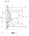
- Fig. 1 illustrates a membrane pump 100, with an example of a pump housing element 1 and a membrane element 6.
- the pump housing element has a chamber 21 with an open end having a first area.
- the membrane element 6 is arrangeable over the open end of the chamber 21 to seal the chamber 21.
- the chamber 21 has bevelled or chamfered walls 20.
- the bevelled or chamfered walls 20 may be straight, such as in the shape of a truncated cone, illustrated in Fig 1 .
- the bevelled or chamfered walls 20 may be convex or concave.
- the walls 20 have more than one radii.
- the walls 20 may have a sinoidal shape, a wave shape, a polynomial shape or spline shaped.
- the chamber 21 is preferably circular but may have any shape such as, a square, rectangular, a polygon or an ellipsoid.
- the bottom area of the chamber 21 has an area 26 which is smaller than the area 25 of the open end.
- the membrane element 6 has a second area 27 and a first central section having a third area 28 (see Fig 2 ).
- the first central section is a central portion of the membrane element.
- the third area is smaller than the second area 27.
- the membrane element has preferably a circular shape but may have any shape, such as a square, rectangular, a polygon or an ellipsoid. Additionally, the first central section has preferably a circular shape but may have any shape, such as a square, rectangular, a polygon or an ellipsoid.
- the shape of the membrane element and first central section does not need to be the same, for example, the membrane element may be a square while the first central section has is circularly shaped.
- the first central section has the same shape as the open end of the chamber.
- the membrane element is preferably made of a flexible or elastic material, such as rubber.
- a flexible or elastic material such as rubber.
- materials that may be used are Chloroprene, EPDM, FKM/FPM, Silicon, TPE or nitrile. But other materials with similar properties known by the skilled person may be used.
- the membrane element may include a second central section having a fourth area 24.
- the second central section has a thickness 23 which is larger than the thickness 22 of the rest of the membrane element.
- the rest of the membrane may be defined as a periphery section surrounding the second central section.
- the ratio between the thicknesses 23 of the second central section to the thickness 22 of the rest of the membrane element may be between 2 to 15.
- the thicker second central section may preferably be shaped to protruding in an opposite direction from the open end of the chamber.
- the walls of the protruding part are bevelled or chamfered, such as a truncated cone or convex or concave.
- the protruding part may be shaped as a segment of a circle or a half circle.
- the thicker second central section of the membrane element may preferably have a smaller area than the opening. Also the thicker second central section of the membrane element may be centrally positioned over the open end of the chamber 21.
- the thickness of the second central section provides for a stiffer central part of the membrane element 6 at a location where a reciprocating pump stroke motion from an actuator, such as a voice coil, a minimotor, a piston, a cam or any other mechanical device that could be used to expose the membrane element 6 to a force, is applied.
- an actuator such as a voice coil, a minimotor, a piston, a cam or any other mechanical device that could be used to expose the membrane element 6 to a force.
- P is the pump pressure
- F is the force of the stroke
- A is the effective pump area
- the shape and the thickness 23 of the thicker section can be varied. The same applies to the design of the inner walls 20 of chamber.
- the membrane element 6 may have a protruding brim 30.
- This brim 30 may be positioned at the periphery edge of the membrane element 6.
- the pump housing 1 may have an enlarged surface surrounding the open end of the chamber 21. This enlarged surface may comprise a groove 31 to fit the protruding brim 30 of the membrane member 6. This may increase the sealing effect in the same fashion as an O-ring.
- the enlarged surface may have an area at least the same as the area of the membrane element 6.
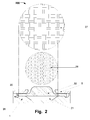
- Fig. 2 illustrates further example of a membrane pump 200.
- the membrane pump 200 has a pump housing member 1 and a membrane element 32.
- the pump housing member 1 and membrane element 32 may be configured in accordance with the description to Fig. 1 .
- the pump housing 1 and could have a chamber 21 which either has a spherical or a flat bottom surface.
- the total area 27 of the membrane element 32 is an elastic membrane area 27 and the part of the membrane element 32 covering the open end of the chamber 21 is the effective pump area 28 (i.e. same as the area 25 of the open end). Additionally, in some examples, when the membrane element 32 has a centrally positioned second central section having a thickness 23 larger than a thickness 22 rest of the membrane element (see Fig 1 ), the effective pump area (i.e. the first central section) 28 is larger than the area 24 of the second central section.
- a major difference between the design illustrated in Fig. 2 and prior art is that the membrane element 32 is not fixed at the edge of the chamber 21. Instead a portion of the membrane element 32 is slidably clamped between an enlarged surface of the pump housing 1 and a second member 5 of the pump housing 1.
- the second member 5 of the pump housing 1 may be a membrane fixing plate. In the area between the second member 5 of the pump housing 1 and the enlarged surface of the pump housing 1, the membrane element 32 is free to move radial and to stretch when a force is applied.
- the membrane element 32 may be fixed at an outer diameter, for example, by a protruding brim 30 fitted into a groove 31 at the enlarged surface of the pump housing 1. In the area between the fixing point and the pump chamber 21 the membrane element 32 is in this configuration still able to freely move radially and stretch.
- the slidebly clamped portion of the membrane element 32 is located between the membrane fixing point (i.e. an outer edge) and the chamber 21.
- the same pump volume can be maintained with less stretching which may increase the membrane fatigue life due to less fatigue stress levels.
- the elastic resistance of the membrane element 32 may consume less of the available pumping force when comparing a pump of a design illustrated in Fig 2 with a prior art pump, both having same pump chamber size. The same effect would also be achieved if a flat membrane element would have been used instead of a membrane element with a thicker mid section as illustrated in the figures.
- the material of the pump housing 1 and the second pump housing member 5 should have low friction and be stiff. Some examples of materials are polymer, metal or composite materials.
- a problem with having a flat membrane surface meeting a concave spherical surface or a flat surface is that the meeting between these two will generate noise and the pump stroke movement will stop instantly causing mechanical vibrations.
- the shape of the pump chamber 21 to have wall being conical or with one or more radii positioned in the area where the membrane element 32 becomes stiffer (thicker) it is possible to decelerate the pump stroke in a progressive way. This will make the stops, when the membrane element is in its end positions silent and also reduces the mechanical vibrations due to the progressive motion deceleration.
- the edge of the second pump housing member 5 i.e. membrane fixing plate
- the edge of the second pump housing member 5 i.e. membrane fixing plate
- the shape of the cavity and membrane fixing plate wall may be designed in many different ways, a straight chamfer, a convex or concave radii etc.
- a preferred ratio between the area 27 of the elastic membrane element to the effective pump area 28, defined by the previous equation 1, is between 1.5 to 10. The longer a stroke is the larger the difference between the two areas has to be.
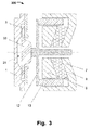
- Fig. 3 illustrates a cross-sectional view of an example of a membrane pump 300.
- the membrane pump 300 comprises a membrane element 33 (according to any of the herein disclosed configurations) and a pump housing 1, and optional second housing member 5 (e.g. membrane fixing plate) and a pump chamber 21.
- the pump chamber 21 has bevelled walls to abutting the area where the membrane element 33 becomes thicker. Hence decelerate the pump stroke in a progressive way.
- the pump further comprises a pump head 12.
- the pump head 12 is abutting the second central section of the membrane element 33.
- the pump head may be mechanically attached to the top of second central section, such as inserted into the second central section or a screw could be used to screw secure them together.
- an adhesive may be used between the top of the second central section and the abutting area of the pump head 12 to affix the two members.
- Examples of adhesives may be, glue, sticky tape, etc.
- the actuator exerting a force on the membrane element 33 is a voice coil.
- the voice coil is used to transmit a reciprocating stroke motions by the pump head 12 to the membrane element 33.
- the voice coil may be a cylindrical voice coil.
- the coil 13 is a circular cylinder structure, which is fixed on the pump head 12 and placed in an air gap.
- the air gap is enclosed by a magnetic cup with conical bottom 7, a conical magnet 8, such as a permanent magnet, and a one side conical pole shoe 9.
- the coil 13 may be a skeletonless coil, entwined by self-adhesive lining. This design may take advantage of the limit space of the air gap, hence it's possible to design smaller membrane pumps 300.
- the magnet cup with a conical bottom 7 is positioned as an inverted M-shape.
- the contact surface between the conical pole shoe 9, the conical magnet 8 and the contact surface between the conical magnet and conical bottom of the magnet cup 7 are all tapered.
- the tapered surfaces are tapered in the same direction. Such structure increases the side area of the conical pole shoe 9, making the magnetic field in the air gap distribute evenly radially.
- the conical shape provides better support for the free shaft of the pump head 12 without adding any volume outside of the cylinder volume.
- the magnetic field is as large as possible when the coil 13 works in the air gap.
- the working principle of the membrane pump 300 is: the coil 13 positioned in the magnetic field formed by the one side conical pole shoe 9, the conical magnet 8 and the magnet cup with conical bottom 7.
- the coil 13 will produce an alternating ampere force to drive the pump head 12 in reciprocating linear motion.
- the pump cycle will produce a cycle of positive and negative pressure in the pump chamber 21.
- pressure in the sealed room is negative, fluid will move through a pump inlet into the chamber 21.
- pressure in the sealed room is positive, the pump 300 will move fluid out through an outlet.
- a small voice coil is adopted to drive membrane to do linear motion so that large transmission mechanisms are eliminated.
- the voice coil does not affect the working life of the pump 300, because the voice coil does not comprise structures that are easily worn out.
- the voice coil drives the membrane element 33 directly without the process of transforming motion to another; hence no intermediate energy is consumed. Further, there is no starting torque problem; hence the pump 300 may start almost instantly by applying a small voltage.
- the voice coil therefore also output a force or a displacement of the pump head 12 to collect a small volume of fluid even at small driving voltage or current.
- the reciprocating motion of the pump head 12 is controlled by controlling the frequency of the voltage. Because the magnitude of reciprocating motion is dependent to the amplitude of the current, the collected flow size may be easily controlled by adjusting the amplitude of the voltage to the voice coil.
Landscapes
- Engineering & Computer Science (AREA)
- Mechanical Engineering (AREA)
- General Engineering & Computer Science (AREA)
- Reciprocating Pumps (AREA)
Abstract
Description
- This invention pertains in general to the field of membrane pumps or diaphragm pumps. More particularly the invention relates to membrane pumps used as sampling pumps in devices for patient monitoring, breath monitoring, anaesthesia monitoring, especially for medical ventilation monitoring and gas analyzers for monitoring gas composition in patient's breathing.
- The membrane pumps have the advantages of simple, compact and good sealing. Membrane pumps have therefore been widely used in medical instrumentations and biochemical analysis as sampling pumps for fluid analysis. In the field of medical ventilation monitoring, the gas measurement module analyses gases extracted from patient breathing circuits by a membrane pump. This may be done for real time monitoring of gas composition in patient's breathing circuits and to get patient's status. Currently, the gas analysis module tends to be smaller with increased reliability and low power exhaust. Hence there are higher requirements for the design of membrane pumps concerning size, life and energy loss.
- Gas monitoring instruments, such as sensors, used to detect gases are precision components sensitive to vibration interference which reduces the measurement accuracy. Under normal circumstances, the sampling pump is a main vibration source in a monitoring module. Thus may introduce noise which could affect the measurement accuracy. The sampling pump is therefore required to provide a more stable sample flow.
- The normal design of a membrane pump has a flat membrane and a pump chamber which is either spherically concave or cylindrical with a flat bottom. Two examples of there types of pumps are Thomas membrane pump or Xavitech membrane pump. Also, membrane pumps have normally membranes that are fixed to outer edges of the membrane, thus defining a pump area. This design is limiting the elastic behaviours of the membrane, is limiting the stroke length and the pump area is limiting the maximum pump pressure (since the area together with the pump force is defining the maximum pump pressure) and the fatigue life. Other problems are when a flat membrane meets a concave or a flat surface of the pump chamber. This will generate noise and the pump stroke will stop instantly causing mechanical vibrations.
- Hence, a new improved design of a membrane pump would be advantageous. Especially a smaller pump with a higher pressure having low vibrations and that runs quieter than known membrane pumps.
- Accordingly, embodiments of the present disclosure preferably seek to mitigate, alleviate or eliminate one or more deficiencies, disadvantages or issues in the art, such as the above-identified, singly or in any combination by providing a device or method according to the appended patent claims for providing progressive pump force regulation, such as in devices for patient monitoring, breath monitoring, anaesthesia monitoring, especially for medical ventilation monitoring and gas analyzers for monitoring gas composition in patient's breathing.
- Disclosed herein are device, system and methods for providing the progressive pump force regulation.
- According to one aspect of the disclosure, a membrane element for a pump having a chamber is disclosed. The membrane element has a first area and comprises a central section with a second area surrounded by a periphery section. The central section is thicker than the periphery section, and the second area of the central section is smaller than an area of an open end of said chamber of which said central section is arranged over.
- According to a further aspect of the disclosure, a pump comprising a membrane element and a pump housing having a chamber with bevelled inner walls is disclosed. The chamber comprises an open end having a third area. The membrane element has a first area, and comprises a central section with a second area which is surrounded by a periphery section, wherein the central section is thicker than the periphery section; further, the second area of the central section is smaller than the third area of the open end of the chamber and the membrane element is arrangable over the pump housing forming a sealed chamber, whereby the central section of the membrane element is arranged over the open end, and the central section is protruding away from the chamber.
- The advantages with this disclosed configuration is that it prevents the stroke from hitting the bottom of the chamber since a pump stroke is decelerated in a progressive way which not only makes the stop silent but also reduces the mechanical vibrations and keep them to a minimum. Further, the deceleration reduces the effective pump area of the membrane closer to the end of a stroke. Since the force of the stroke is constant, the pump becomes stronger closer to the end of the stroke.
- In some example, the central section has a circular shape.
- The membrane is made of an elastic material, such as rubber and/or is selected from a list including: Chloroprene, EPDM, FKM/FPM, Silicon, TPE or nitrile.
- In some examples the thickness ratio between the central section to the periphery section is between 2 to 15.
- In some examples has the first section a protruding brim. This protruding brim works as an O-ring to increase the sealing effect.
- In some examples has the thicker central section bevelled outer walls with a base larger than a top section, such as a truncated cone.
- In some examples of the disclosure may the central section and the chamber both have circular shapes.
- In some examples of the disclosure may the bevelled inner walls be straight, or concave, or convex, or have two or more radii, or have a sinoidal shape, or be of shaped as a polynomial of higher order.
- In some examples has the membrane element an effective pump area with an area substantially the same as the third area of the open end of the chamber.
- In some examples may the pump housing have an enlarged surface surrounding the open end of the chamber with an area with at least the same size as the membrane element.
- In some examples of the disclosure may the membrane element clamped between the enlarged surface of the pump housing and a second member of the pump housing.
- The advantages with this configuration are that by holding a membrane element slidably fixed at a larger diameter than the actual working diameter (area) is that the membrane is free to move radial and stretch. Hence a longer pump stroke may be achieved (i.e. more volume can be pumped per stroke). Also, due to the radial movement, the same pump volume can be maintained with less stretching which will increase life of the membrane due to lower fatigue stress levels and more effective use of the available pump force may be obtained.
- The enlarged surface may comprises a groove to fit said protruding brim of the membrane member.
- According to another aspect of the disclosure, a method for progressive pump force regulation is disclosed. The method comprising providing a pump according to the discloser herein, and applying a reciprocating stroke motion on the central section of the membrane element. The motion may be restricted by the bevelled inner walls of the chamber at a position where the central section of the membrane element becomes thicker.
- It should be emphasized that the term "comprises/comprising" when used in this specification is taken to specify the presence of stated features, integers, steps or components but does not preclude the presence or addition of one or more other features, integers, steps, components or groups thereof.
- These and other aspects, features and advantages of which examples of the disclosure are capable of will be apparent and elucidated from the following description of embodiments of the present disclosure, reference being made to the accompanying drawings, in which
-
Fig. 1 is illustrating a cross-sectional schematic overview of an example of a pump house and a membrane. -
Fig. 2 is illustrating a cross-sectional schematic overview of an example of a pump house and a membrane. -
Fig. 3 is illustrating a cross-sectional schematic overview of a membrane pump. - Specific examples of the disclosure will be described with reference to the accompanying drawings. This disclosure may, however, be embodied in many different forms and should not be construed as limited to the embodiments set forth herein; rather, these embodiments are provided so that this disclosure will be thorough and complete, and will fully convey the scope of the invention to those skilled in the art. The terminology used in the detailed description of the embodiments illustrated in the accompanying drawings is not intended to be limiting of the disclosure. In the drawings, like numbers refer to like elements.
- The following description focuses on examples of the present disclosure applicable to a membrane element and to a membrane pump. The membrane pump is to be used as a sampling pump in devices for patient monitoring, breath monitoring, anaesthesia monitoring, especially medical ventilation monitoring and gas analyzers for monitoring gas composition in patient's breathing. However, it will be appreciated that the invention is not limited to this application but may be applied to many other systems where a fluid pump is required.
-
Fig. 1 illustrates amembrane pump 100, with an example of apump housing element 1 and amembrane element 6. The pump housing element has achamber 21 with an open end having a first area. Themembrane element 6 is arrangeable over the open end of thechamber 21 to seal thechamber 21. - The
chamber 21 has bevelled or chamferedwalls 20. The bevelled or chamferedwalls 20 may be straight, such as in the shape of a truncated cone, illustrated inFig 1 . In some examples, the bevelled or chamferedwalls 20 may be convex or concave. In other examples, thewalls 20 have more than one radii. In other configurations thewalls 20 may have a sinoidal shape, a wave shape, a polynomial shape or spline shaped. Thechamber 21 is preferably circular but may have any shape such as, a square, rectangular, a polygon or an ellipsoid. - Additionally and/or alternatively, in some examples, the bottom area of the
chamber 21 has anarea 26 which is smaller than thearea 25 of the open end. - The
membrane element 6 has asecond area 27 and a first central section having a third area 28 (seeFig 2 ). The first central section is a central portion of the membrane element. Thus the third area is smaller than thesecond area 27. - The membrane element has preferably a circular shape but may have any shape, such as a square, rectangular, a polygon or an ellipsoid. Additionally, the first central section has preferably a circular shape but may have any shape, such as a square, rectangular, a polygon or an ellipsoid.
- The shape of the membrane element and first central section does not need to be the same, for example, the membrane element may be a square while the first central section has is circularly shaped. Preferably, the first central section has the same shape as the open end of the chamber.
- The membrane element is preferably made of a flexible or elastic material, such as rubber. Examples of materials that may be used are Chloroprene, EPDM, FKM/FPM, Silicon, TPE or nitrile. But other materials with similar properties known by the skilled person may be used.
- Additionally and/or alternatively, the membrane element may include a second central section having a
fourth area 24. The second central section has athickness 23 which is larger than thethickness 22 of the rest of the membrane element. The rest of the membrane may be defined as a periphery section surrounding the second central section. Preferably the ratio between thethicknesses 23 of the second central section to thethickness 22 of the rest of the membrane element may be between 2 to 15. - The thicker second central section may preferably be shaped to protruding in an opposite direction from the open end of the chamber. The walls of the protruding part are bevelled or chamfered, such as a truncated cone or convex or concave. Alternatively, in some examples, the protruding part may be shaped as a segment of a circle or a half circle.
- Additionally, in some examples, the thicker second central section of the membrane element may preferably have a smaller area than the opening. Also the thicker second central section of the membrane element may be centrally positioned over the open end of the
chamber 21. - The thickness of the second central section provides for a stiffer central part of the
membrane element 6 at a location where a reciprocating pump stroke motion from an actuator, such as a voice coil, a minimotor, a piston, a cam or any other mechanical device that could be used to expose themembrane element 6 to a force, is applied. When the stoke motion presses the membrane element towards thechamber 21 the downward motion of the thicker second central section will be restricted by the bevelledinner walls 20 of thechamber 21 at a position where the second central section of themembrane element 6 becomes thicker. This will decelerate the pump stroke in a progressive way. This will not only provide a silent the stop of the stroke but also reduce mechanical vibrations to a minimum. - Another advantage is that when the pump stroke reaches deeper into the chamber the actual pumping area, e.g. the effective pump area, becomes smaller but the force of the stroke is the same. Hence the
pump 100 becomes stronger, i.e. is able to generate a higher pressure. This is in accordance with the equation:
- where, P is the pump pressure, F is the force of the stroke and A is the effective pump area.
- Further, this configuration prevents the stroke to hit the bottom of the chamber.
- Depending on the desired pump characteristics the shape and the
thickness 23 of the thicker section can be varied. The same applies to the design of theinner walls 20 of chamber. - Additionally, in some examples, the
membrane element 6 may have a protrudingbrim 30. Thisbrim 30 may be positioned at the periphery edge of themembrane element 6. Further, thepump housing 1 may have an enlarged surface surrounding the open end of thechamber 21. This enlarged surface may comprise agroove 31 to fit the protrudingbrim 30 of themembrane member 6. This may increase the sealing effect in the same fashion as an O-ring. - Additionally, in some examples, the enlarged surface may have an area at least the same as the area of the
membrane element 6. -
Fig. 2 illustrates further example of amembrane pump 200. Themembrane pump 200 has apump housing member 1 and amembrane element 32. In the illustration thepump housing member 1 andmembrane element 32 may be configured in accordance with the description toFig. 1 . - Alternatively, in some examples, the
pump housing 1 and could have achamber 21 which either has a spherical or a flat bottom surface. - The
total area 27 of themembrane element 32 is anelastic membrane area 27 and the part of themembrane element 32 covering the open end of thechamber 21 is the effective pump area 28 (i.e. same as thearea 25 of the open end). Additionally, in some examples, when themembrane element 32 has a centrally positioned second central section having athickness 23 larger than athickness 22 rest of the membrane element (seeFig 1 ), the effective pump area (i.e. the first central section) 28 is larger than thearea 24 of the second central section. - A major difference between the design illustrated in
Fig. 2 and prior art is that themembrane element 32 is not fixed at the edge of thechamber 21. Instead a portion of themembrane element 32 is slidably clamped between an enlarged surface of thepump housing 1 and asecond member 5 of thepump housing 1. Thesecond member 5 of thepump housing 1 may be a membrane fixing plate. In the area between thesecond member 5 of thepump housing 1 and the enlarged surface of thepump housing 1, themembrane element 32 is free to move radial and to stretch when a force is applied. - Additionally, in some examples, the
membrane element 32 may be fixed at an outer diameter, for example, by a protrudingbrim 30 fitted into agroove 31 at the enlarged surface of thepump housing 1. In the area between the fixing point and thepump chamber 21 themembrane element 32 is in this configuration still able to freely move radially and stretch. - By letting a portion of the
membrane element 32 slide between two flat surfaces of the enlarged surface of thepump housing 1 and thesecond member 5 anelastic area 27 which is larger than the actualeffective pump area 28 is used. This allows themembrane element 32 to stretch more, i.e. enabling a longer stroke, hence more volume per stroke. - The slidebly clamped portion of the
membrane element 32 is located between the membrane fixing point (i.e. an outer edge) and thechamber 21. When keeping the length of the stroke, the same pump volume can be maintained with less stretching which may increase the membrane fatigue life due to less fatigue stress levels. Also, the elastic resistance of themembrane element 32 may consume less of the available pumping force when comparing a pump of a design illustrated inFig 2 with a prior art pump, both having same pump chamber size. The same effect would also be achieved if a flat membrane element would have been used instead of a membrane element with a thicker mid section as illustrated in the figures. - The material of the
pump housing 1 and the secondpump housing member 5 should have low friction and be stiff. Some examples of materials are polymer, metal or composite materials. - A problem with having a flat membrane surface meeting a concave spherical surface or a flat surface is that the meeting between these two will generate noise and the pump stroke movement will stop instantly causing mechanical vibrations. By designing the shape of the
pump chamber 21 to have wall being conical or with one or more radii positioned in the area where themembrane element 32 becomes stiffer (thicker) it is possible to decelerate the pump stroke in a progressive way. This will make the stops, when the membrane element is in its end positions silent and also reduces the mechanical vibrations due to the progressive motion deceleration. - Additionally and/or alternatively, by designing the edge of the second pump housing member 5 (i.e. membrane fixing plate) to be conical or with one or more radii positioned in the area where the
membrane element 32 becomes stiffer (thicker) it may also be possible to decelerate the pump stroke in a progressive way. This will make the stops, when the membrane element is in its turning point silent and also reduces the mechanical vibrations due to the progressive motion deceleration. - Depending on the desired pump characteristic and the obtainable amount of force, the shape of the cavity and membrane fixing plate wall may be designed in many different ways, a straight chamfer, a convex or concave radii etc.
- Additionally, in some examples of a
pump 200 according to the illustration ofFig. 2 a preferred ratio between thearea 27 of the elastic membrane element to theeffective pump area 28, defined by theprevious equation 1, is between 1.5 to 10. The longer a stroke is the larger the difference between the two areas has to be. -
Fig. 3 illustrates a cross-sectional view of an example of amembrane pump 300. Themembrane pump 300 comprises a membrane element 33 (according to any of the herein disclosed configurations) and apump housing 1, and optional second housing member 5 (e.g. membrane fixing plate) and apump chamber 21. In this example, thepump chamber 21 has bevelled walls to abutting the area where themembrane element 33 becomes thicker. Hence decelerate the pump stroke in a progressive way. - The pump further comprises a
pump head 12. In this example, thepump head 12 is abutting the second central section of themembrane element 33. Alternatively, in some examples, the pump head may be mechanically attached to the top of second central section, such as inserted into the second central section or a screw could be used to screw secure them together. When using apump head 12 abutting the top of the second central section an adhesive may be used between the top of the second central section and the abutting area of thepump head 12 to affix the two members. - Examples of adhesives may be, glue, sticky tape, etc.
- In this example depicted in
Fig 3 , the actuator exerting a force on themembrane element 33 is a voice coil. The voice coil is used to transmit a reciprocating stroke motions by thepump head 12 to themembrane element 33. Specifically, the voice coil may be a cylindrical voice coil. - In one example, the
coil 13 is a circular cylinder structure, which is fixed on thepump head 12 and placed in an air gap. The air gap is enclosed by a magnetic cup withconical bottom 7, aconical magnet 8, such as a permanent magnet, and a one sideconical pole shoe 9. - Additionally, in order to maximize the utilization of the magnetic field in the air gap and reduce the size of the
pump 300, thecoil 13 may be a skeletonless coil, entwined by self-adhesive lining. This design may take advantage of the limit space of the air gap, hence it's possible to design smaller membrane pumps 300. - In the example illustrated in
Fig. 3 , the magnet cup with aconical bottom 7 is positioned as an inverted M-shape. The contact surface between theconical pole shoe 9, theconical magnet 8 and the contact surface between the conical magnet and conical bottom of themagnet cup 7 are all tapered. The tapered surfaces are tapered in the same direction. Such structure increases the side area of theconical pole shoe 9, making the magnetic field in the air gap distribute evenly radially. - This design allows for a larger magnet, better distribution of the magnetic flux inside the
pole shoe 9. Further, the conical shape provides better support for the free shaft of thepump head 12 without adding any volume outside of the cylinder volume. Thus the magnetic field is as large as possible when thecoil 13 works in the air gap. - In
Fig 3 , the working principle of themembrane pump 300 is: thecoil 13 positioned in the magnetic field formed by the one sideconical pole shoe 9, theconical magnet 8 and the magnet cup withconical bottom 7. When an alternating voltage is transmitted to thecoil 13, thecoil 13 will produce an alternating ampere force to drive thepump head 12 in reciprocating linear motion. - The pump cycle will produce a cycle of positive and negative pressure in the
pump chamber 21. When pressure in the sealed room is negative, fluid will move through a pump inlet into thechamber 21. When pressure in the sealed room is positive, thepump 300 will move fluid out through an outlet. - In the example illustrated in
Fig 3 , a small voice coil is adopted to drive membrane to do linear motion so that large transmission mechanisms are eliminated. Thus the size of themembrane pump 300 is reduced. The voice coil does not affect the working life of thepump 300, because the voice coil does not comprise structures that are easily worn out. The voice coil drives themembrane element 33 directly without the process of transforming motion to another; hence no intermediate energy is consumed. Further, there is no starting torque problem; hence thepump 300 may start almost instantly by applying a small voltage. The voice coil therefore also output a force or a displacement of thepump head 12 to collect a small volume of fluid even at small driving voltage or current. - Also, the reciprocating motion of the
pump head 12 is controlled by controlling the frequency of the voltage. Because the magnitude of reciprocating motion is dependent to the amplitude of the current, the collected flow size may be easily controlled by adjusting the amplitude of the voltage to the voice coil. - While several embodiments of the present invention have been described and illustrated herein, those of ordinary skill in the art will readily envision a variety of other means and/or structures for performing the functions and/or obtaining the results and/or one or more of the advantages described herein, and each of such variations and/or modifications is deemed to be within the scope of the present invention. More generally, those skilled in the art will readily appreciate that all parameters, dimensions, materials, and configurations described herein are meant to be exemplary and that the actual parameters, dimensions, materials, and/or configurations will depend upon the specific application or applications for which the teachings of the present invention is/are used.
Claims (15)
- A pump comprising a membrane element and a pump housing having a chamber with bevelled inner walls, said chamber comprises an open end having a third area; said membrane element has a first area, and comprises a central section with a second area which is surrounded by a periphery section, wherein said central section is thicker than said periphery section; further, said second area of said central section is smaller than said third area of said open end of said chamber and said membrane element is arrangable over said pump housing forming a sealed chamber, whereby said central section of said membrane element is arranged over said open end, and said thickness of said central section is shaped to protrude away from said chamber.
- The pump element of claim 1, wherein said central section has a circular shape.
- The pump element of claim 1 or 2, wherein said membrane is made of an elastic material.
- The pump of claim 3, wherein said material is rubber and/or is selected from a list including: Chloroprene, EPDM, FKM/FPM, Silicon, TPE or nitrile.
- The pump of any of claims 1 to 4, wherein the thickness ratio between said central section to said periphery section is between 2 to 15.
- The pump of any of claims 1 to 5, wherein said membrane element has a protruding brim.
- The pump element according to any of claims 1 to 6, wherein said central section has bevelled outer walls with a base larger than a top section, such as a truncated cone.
- The pump according to any of claims 1 to 7,
wherein said central section and said chamber both have circular shapes. - The pump according to claims 1 to 8, wherein said bevelled inner walls are straight, or concave, or convex, or have two or more radii, or have a sinoidal shape, or be of shaped as a polynomial of higher order.
- The pump according to any of claims 1 to 9,
wherein said membrane element has an effective pump area with an area substantially the same as said third area of said open end of said chamber. - The pump according to any of claims 1 to 10,
wherein said pump housing has an enlarged surface surrounding said open end of said chamber with an area with at least the same size as said membrane element. - The pump according to claim 11, wherein said membrane element is slidably clamped between said enlarged surface of said pump housing and a second member of said pump housing.
- The pump according to any of claims 11 to 12,
wherein said enlarged surface comprises a groove to fit said protruding brim of said membrane member. - A method for progressive pump force regulation, comprising:providing a pump according to any of claim 1 to 13;applying a reciprocating stroke motion on said central section of said membrane element; andwherein said motion is restricted by said bevelled inner walls of said chamber at a position where said central section of said membrane element becomes thicker.
- Use of a pump according to any of claim 1 to 14 for patient monitoring, breath monitoring, anaesthesia monitoring.
Priority Applications (1)
| Application Number | Priority Date | Filing Date | Title |
|---|---|---|---|
| EP13193067.9A EP2733354B1 (en) | 2012-11-15 | 2013-11-15 | Progressive pump force regulation |
Applications Claiming Priority (3)
| Application Number | Priority Date | Filing Date | Title |
|---|---|---|---|
| US201261726962P | 2012-11-15 | 2012-11-15 | |
| EP12192847 | 2012-11-15 | ||
| EP13193067.9A EP2733354B1 (en) | 2012-11-15 | 2013-11-15 | Progressive pump force regulation |
Publications (2)
| Publication Number | Publication Date |
|---|---|
| EP2733354A1 true EP2733354A1 (en) | 2014-05-21 |
| EP2733354B1 EP2733354B1 (en) | 2020-06-17 |
Family
ID=47191609
Family Applications (1)
| Application Number | Title | Priority Date | Filing Date |
|---|---|---|---|
| EP13193067.9A Active EP2733354B1 (en) | 2012-11-15 | 2013-11-15 | Progressive pump force regulation |
Country Status (3)
| Country | Link |
|---|---|
| EP (1) | EP2733354B1 (en) |
| CN (1) | CN104813027B (en) |
| WO (1) | WO2014076234A1 (en) |
Families Citing this family (1)
| Publication number | Priority date | Publication date | Assignee | Title |
|---|---|---|---|---|
| CN108980016B (en) * | 2018-09-11 | 2024-09-20 | 厦门金升泵电子科技有限公司 | A gas-liquid vacuum integrated micro diaphragm pump |
Citations (4)
| Publication number | Priority date | Publication date | Assignee | Title |
|---|---|---|---|---|
| FR2482674A1 (en) * | 1980-05-16 | 1981-11-20 | Wagner Gmbh J | DIAPHRAGM FOR HIGH PRESSURE FILLING PUMPS, COMPRESSORS OR THE LIKE |
| US20040076526A1 (en) * | 2002-10-22 | 2004-04-22 | Smc Kabushiki Kaisha | Pump apparatus |
| DE102004047720A1 (en) * | 2003-11-03 | 2005-04-21 | Trelleborg Sealing Solutions U | Elastomeric membrane fabrication involves forming mixture of elastomer and dispersed fibres, supplying mixture to mold, and press molding |
| US20070240564A1 (en) * | 2006-04-13 | 2007-10-18 | Toray Engineering Co., Ltd. | Piston, method of producing the piston, and pump having the piston |
Family Cites Families (3)
| Publication number | Priority date | Publication date | Assignee | Title |
|---|---|---|---|---|
| GB9614866D0 (en) * | 1996-07-15 | 1996-09-04 | Charles Austen Pumps Ltd | Rotary pump |
| JP2000190071A (en) * | 1998-12-21 | 2000-07-11 | Taiyo Denki Sangyo Kk | Solder adsorption machine |
| JP3462448B2 (en) * | 2000-05-25 | 2003-11-05 | 株式会社タクミナ | Diaphragm and reciprocating pump |
-
2013
- 2013-11-15 CN CN201380059784.9A patent/CN104813027B/en active Active
- 2013-11-15 EP EP13193067.9A patent/EP2733354B1/en active Active
- 2013-11-15 WO PCT/EP2013/073941 patent/WO2014076234A1/en not_active Ceased
Patent Citations (4)
| Publication number | Priority date | Publication date | Assignee | Title |
|---|---|---|---|---|
| FR2482674A1 (en) * | 1980-05-16 | 1981-11-20 | Wagner Gmbh J | DIAPHRAGM FOR HIGH PRESSURE FILLING PUMPS, COMPRESSORS OR THE LIKE |
| US20040076526A1 (en) * | 2002-10-22 | 2004-04-22 | Smc Kabushiki Kaisha | Pump apparatus |
| DE102004047720A1 (en) * | 2003-11-03 | 2005-04-21 | Trelleborg Sealing Solutions U | Elastomeric membrane fabrication involves forming mixture of elastomer and dispersed fibres, supplying mixture to mold, and press molding |
| US20070240564A1 (en) * | 2006-04-13 | 2007-10-18 | Toray Engineering Co., Ltd. | Piston, method of producing the piston, and pump having the piston |
Also Published As
| Publication number | Publication date |
|---|---|
| WO2014076234A1 (en) | 2014-05-22 |
| CN104813027A (en) | 2015-07-29 |
| CN104813027B (en) | 2017-05-24 |
| EP2733354B1 (en) | 2020-06-17 |
Similar Documents
| Publication | Publication Date | Title |
|---|---|---|
| EP2733355B1 (en) | Extended elasticity of pump membrane with conserved pump force | |
| US10294933B2 (en) | Systems and methods for supplying reduced pressure using a disc pump with electrostatic actuation | |
| US9360004B2 (en) | Progressive pump force regulation | |
| CN103671462B (en) | Based on the piezoelectricity valve free pump sucker of parallel connection compliant mechanism | |
| CN108223339A (en) | Cavity pump and the method for running cavity pump | |
| KR20130064020A (en) | Electromagnetic diaphragm pump | |
| EP3447292A8 (en) | Actuating-type gas guiding device | |
| EP2733354B1 (en) | Progressive pump force regulation | |
| CN113007076B (en) | An electromagnetic diaphragm metering pump based on magnetorheological elastomer | |
| KR20170012198A (en) | Diaphragm affixation structure, and diaphragm pump and valve device each comprising same | |
| US20100111715A1 (en) | Air supply mechanism for ventricular assist system | |
| EP2733834A1 (en) | An improved magnetic circuit | |
| US10760558B2 (en) | Multistage compressor with magnetically actated compression stage | |
| US20060034709A1 (en) | Linear pump with exhaust pulsation attenuation | |
| Dai et al. | A Magnetic Coupling Pneumatic Diaphragm Pump Driven by Dielectric Elastomers | |
| CN103216432B (en) | Diaphragm pump and gas analyzer | |
| US20050265876A1 (en) | Fluid circulator with rigid diaphragm | |
| RU2278993C1 (en) | Diaphragm pump (versions) | |
| CN223676053U (en) | A reciprocating unidirectional damper | |
| CN113236518B (en) | Oil-water separation structure and water pump | |
| JP2019120213A (en) | Oilless compressor | |
| CN208330673U (en) | A kind of air-breathing noise reducing mechanism of Linearkompressor | |
| CN104421137B (en) | A kind of novel pressure electric pump | |
| JP2006300037A (en) | Piezoelectric diaphragm pump | |
| CN1981132A (en) | Fluid Circulator with Rigid Diaphragm |
Legal Events
| Date | Code | Title | Description |
|---|---|---|---|
| PUAI | Public reference made under article 153(3) epc to a published international application that has entered the european phase |
Free format text: ORIGINAL CODE: 0009012 |
|
| 17P | Request for examination filed |
Effective date: 20131115 |
|
| AK | Designated contracting states |
Kind code of ref document: A1 Designated state(s): AL AT BE BG CH CY CZ DE DK EE ES FI FR GB GR HR HU IE IS IT LI LT LU LV MC MK MT NL NO PL PT RO RS SE SI SK SM TR |
|
| AX | Request for extension of the european patent |
Extension state: BA ME |
|
| R17P | Request for examination filed (corrected) |
Effective date: 20141121 |
|
| RBV | Designated contracting states (corrected) |
Designated state(s): AL AT BE BG CH CY CZ DE DK EE ES FI FR GB GR HR HU IE IS IT LI LT LU LV MC MK MT NL NO PL PT RO RS SE SI SK SM TR |
|
| RAP1 | Party data changed (applicant data changed or rights of an application transferred) |
Owner name: SHENZHEN MINDRAY BIO-MEDICAL ELECTRONICS CO., LTD. |
|
| STAA | Information on the status of an ep patent application or granted ep patent |
Free format text: STATUS: EXAMINATION IS IN PROGRESS |
|
| 17Q | First examination report despatched |
Effective date: 20181221 |
|
| GRAP | Despatch of communication of intention to grant a patent |
Free format text: ORIGINAL CODE: EPIDOSNIGR1 |
|
| STAA | Information on the status of an ep patent application or granted ep patent |
Free format text: STATUS: GRANT OF PATENT IS INTENDED |
|
| INTG | Intention to grant announced |
Effective date: 20200102 |
|
| GRAJ | Information related to disapproval of communication of intention to grant by the applicant or resumption of examination proceedings by the epo deleted |
Free format text: ORIGINAL CODE: EPIDOSDIGR1 |
|
| STAA | Information on the status of an ep patent application or granted ep patent |
Free format text: STATUS: EXAMINATION IS IN PROGRESS |
|
| GRAJ | Information related to disapproval of communication of intention to grant by the applicant or resumption of examination proceedings by the epo deleted |
Free format text: ORIGINAL CODE: EPIDOSDIGR1 |
|
| GRAR | Information related to intention to grant a patent recorded |
Free format text: ORIGINAL CODE: EPIDOSNIGR71 |
|
| GRAS | Grant fee paid |
Free format text: ORIGINAL CODE: EPIDOSNIGR3 |
|
| STAA | Information on the status of an ep patent application or granted ep patent |
Free format text: STATUS: GRANT OF PATENT IS INTENDED |
|
| GRAA | (expected) grant |
Free format text: ORIGINAL CODE: 0009210 |
|
| STAA | Information on the status of an ep patent application or granted ep patent |
Free format text: STATUS: THE PATENT HAS BEEN GRANTED |
|
| INTC | Intention to grant announced (deleted) | ||
| AK | Designated contracting states |
Kind code of ref document: B1 Designated state(s): AL AT BE BG CH CY CZ DE DK EE ES FI FR GB GR HR HU IE IS IT LI LT LU LV MC MK MT NL NO PL PT RO RS SE SI SK SM TR |
|
| INTG | Intention to grant announced |
Effective date: 20200508 |
|
| REG | Reference to a national code |
Ref country code: GB Ref legal event code: FG4D |
|
| REG | Reference to a national code |
Ref country code: CH Ref legal event code: EP |
|
| REG | Reference to a national code |
Ref country code: IE Ref legal event code: FG4D |
|
| REG | Reference to a national code |
Ref country code: DE Ref legal event code: R096 Ref document number: 602013069885 Country of ref document: DE |
|
| REG | Reference to a national code |
Ref country code: AT Ref legal event code: REF Ref document number: 1281618 Country of ref document: AT Kind code of ref document: T Effective date: 20200715 |
|
| REG | Reference to a national code |
Ref country code: NL Ref legal event code: FP |
|
| PG25 | Lapsed in a contracting state [announced via postgrant information from national office to epo] |
Ref country code: NO Free format text: LAPSE BECAUSE OF FAILURE TO SUBMIT A TRANSLATION OF THE DESCRIPTION OR TO PAY THE FEE WITHIN THE PRESCRIBED TIME-LIMIT Effective date: 20200917 Ref country code: FI Free format text: LAPSE BECAUSE OF FAILURE TO SUBMIT A TRANSLATION OF THE DESCRIPTION OR TO PAY THE FEE WITHIN THE PRESCRIBED TIME-LIMIT Effective date: 20200617 Ref country code: LT Free format text: LAPSE BECAUSE OF FAILURE TO SUBMIT A TRANSLATION OF THE DESCRIPTION OR TO PAY THE FEE WITHIN THE PRESCRIBED TIME-LIMIT Effective date: 20200617 Ref country code: SE Free format text: LAPSE BECAUSE OF FAILURE TO SUBMIT A TRANSLATION OF THE DESCRIPTION OR TO PAY THE FEE WITHIN THE PRESCRIBED TIME-LIMIT Effective date: 20200617 Ref country code: GR Free format text: LAPSE BECAUSE OF FAILURE TO SUBMIT A TRANSLATION OF THE DESCRIPTION OR TO PAY THE FEE WITHIN THE PRESCRIBED TIME-LIMIT Effective date: 20200918 |
|
| REG | Reference to a national code |
Ref country code: LT Ref legal event code: MG4D |
|
| PG25 | Lapsed in a contracting state [announced via postgrant information from national office to epo] |
Ref country code: BG Free format text: LAPSE BECAUSE OF FAILURE TO SUBMIT A TRANSLATION OF THE DESCRIPTION OR TO PAY THE FEE WITHIN THE PRESCRIBED TIME-LIMIT Effective date: 20200917 Ref country code: RS Free format text: LAPSE BECAUSE OF FAILURE TO SUBMIT A TRANSLATION OF THE DESCRIPTION OR TO PAY THE FEE WITHIN THE PRESCRIBED TIME-LIMIT Effective date: 20200617 Ref country code: LV Free format text: LAPSE BECAUSE OF FAILURE TO SUBMIT A TRANSLATION OF THE DESCRIPTION OR TO PAY THE FEE WITHIN THE PRESCRIBED TIME-LIMIT Effective date: 20200617 Ref country code: HR Free format text: LAPSE BECAUSE OF FAILURE TO SUBMIT A TRANSLATION OF THE DESCRIPTION OR TO PAY THE FEE WITHIN THE PRESCRIBED TIME-LIMIT Effective date: 20200617 |
|
| REG | Reference to a national code |
Ref country code: AT Ref legal event code: MK05 Ref document number: 1281618 Country of ref document: AT Kind code of ref document: T Effective date: 20200617 |
|
| PG25 | Lapsed in a contracting state [announced via postgrant information from national office to epo] |
Ref country code: AL Free format text: LAPSE BECAUSE OF FAILURE TO SUBMIT A TRANSLATION OF THE DESCRIPTION OR TO PAY THE FEE WITHIN THE PRESCRIBED TIME-LIMIT Effective date: 20200617 |
|
| PG25 | Lapsed in a contracting state [announced via postgrant information from national office to epo] |
Ref country code: SM Free format text: LAPSE BECAUSE OF FAILURE TO SUBMIT A TRANSLATION OF THE DESCRIPTION OR TO PAY THE FEE WITHIN THE PRESCRIBED TIME-LIMIT Effective date: 20200617 Ref country code: EE Free format text: LAPSE BECAUSE OF FAILURE TO SUBMIT A TRANSLATION OF THE DESCRIPTION OR TO PAY THE FEE WITHIN THE PRESCRIBED TIME-LIMIT Effective date: 20200617 Ref country code: RO Free format text: LAPSE BECAUSE OF FAILURE TO SUBMIT A TRANSLATION OF THE DESCRIPTION OR TO PAY THE FEE WITHIN THE PRESCRIBED TIME-LIMIT Effective date: 20200617 Ref country code: CZ Free format text: LAPSE BECAUSE OF FAILURE TO SUBMIT A TRANSLATION OF THE DESCRIPTION OR TO PAY THE FEE WITHIN THE PRESCRIBED TIME-LIMIT Effective date: 20200617 Ref country code: AT Free format text: LAPSE BECAUSE OF FAILURE TO SUBMIT A TRANSLATION OF THE DESCRIPTION OR TO PAY THE FEE WITHIN THE PRESCRIBED TIME-LIMIT Effective date: 20200617 Ref country code: PT Free format text: LAPSE BECAUSE OF FAILURE TO SUBMIT A TRANSLATION OF THE DESCRIPTION OR TO PAY THE FEE WITHIN THE PRESCRIBED TIME-LIMIT Effective date: 20201019 Ref country code: ES Free format text: LAPSE BECAUSE OF FAILURE TO SUBMIT A TRANSLATION OF THE DESCRIPTION OR TO PAY THE FEE WITHIN THE PRESCRIBED TIME-LIMIT Effective date: 20200617 |
|
| PG25 | Lapsed in a contracting state [announced via postgrant information from national office to epo] |
Ref country code: PL Free format text: LAPSE BECAUSE OF FAILURE TO SUBMIT A TRANSLATION OF THE DESCRIPTION OR TO PAY THE FEE WITHIN THE PRESCRIBED TIME-LIMIT Effective date: 20200617 Ref country code: SK Free format text: LAPSE BECAUSE OF FAILURE TO SUBMIT A TRANSLATION OF THE DESCRIPTION OR TO PAY THE FEE WITHIN THE PRESCRIBED TIME-LIMIT Effective date: 20200617 Ref country code: IS Free format text: LAPSE BECAUSE OF FAILURE TO SUBMIT A TRANSLATION OF THE DESCRIPTION OR TO PAY THE FEE WITHIN THE PRESCRIBED TIME-LIMIT Effective date: 20201017 |
|
| REG | Reference to a national code |
Ref country code: DE Ref legal event code: R097 Ref document number: 602013069885 Country of ref document: DE |
|
| PLBE | No opposition filed within time limit |
Free format text: ORIGINAL CODE: 0009261 |
|
| STAA | Information on the status of an ep patent application or granted ep patent |
Free format text: STATUS: NO OPPOSITION FILED WITHIN TIME LIMIT |
|
| PG25 | Lapsed in a contracting state [announced via postgrant information from national office to epo] |
Ref country code: DK Free format text: LAPSE BECAUSE OF FAILURE TO SUBMIT A TRANSLATION OF THE DESCRIPTION OR TO PAY THE FEE WITHIN THE PRESCRIBED TIME-LIMIT Effective date: 20200617 |
|
| 26N | No opposition filed |
Effective date: 20210318 |
|
| PG25 | Lapsed in a contracting state [announced via postgrant information from national office to epo] |
Ref country code: SI Free format text: LAPSE BECAUSE OF FAILURE TO SUBMIT A TRANSLATION OF THE DESCRIPTION OR TO PAY THE FEE WITHIN THE PRESCRIBED TIME-LIMIT Effective date: 20200617 |
|
| PG25 | Lapsed in a contracting state [announced via postgrant information from national office to epo] |
Ref country code: MC Free format text: LAPSE BECAUSE OF FAILURE TO SUBMIT A TRANSLATION OF THE DESCRIPTION OR TO PAY THE FEE WITHIN THE PRESCRIBED TIME-LIMIT Effective date: 20200617 |
|
| REG | Reference to a national code |
Ref country code: CH Ref legal event code: PL |
|
| PG25 | Lapsed in a contracting state [announced via postgrant information from national office to epo] |
Ref country code: LU Free format text: LAPSE BECAUSE OF NON-PAYMENT OF DUE FEES Effective date: 20201115 |
|
| REG | Reference to a national code |
Ref country code: BE Ref legal event code: MM Effective date: 20201130 |
|
| PG25 | Lapsed in a contracting state [announced via postgrant information from national office to epo] |
Ref country code: LI Free format text: LAPSE BECAUSE OF NON-PAYMENT OF DUE FEES Effective date: 20201130 Ref country code: CH Free format text: LAPSE BECAUSE OF NON-PAYMENT OF DUE FEES Effective date: 20201130 |
|
| PG25 | Lapsed in a contracting state [announced via postgrant information from national office to epo] |
Ref country code: IE Free format text: LAPSE BECAUSE OF NON-PAYMENT OF DUE FEES Effective date: 20201115 |
|
| PG25 | Lapsed in a contracting state [announced via postgrant information from national office to epo] |
Ref country code: TR Free format text: LAPSE BECAUSE OF FAILURE TO SUBMIT A TRANSLATION OF THE DESCRIPTION OR TO PAY THE FEE WITHIN THE PRESCRIBED TIME-LIMIT Effective date: 20200617 Ref country code: MT Free format text: LAPSE BECAUSE OF FAILURE TO SUBMIT A TRANSLATION OF THE DESCRIPTION OR TO PAY THE FEE WITHIN THE PRESCRIBED TIME-LIMIT Effective date: 20200617 Ref country code: CY Free format text: LAPSE BECAUSE OF FAILURE TO SUBMIT A TRANSLATION OF THE DESCRIPTION OR TO PAY THE FEE WITHIN THE PRESCRIBED TIME-LIMIT Effective date: 20200617 |
|
| PG25 | Lapsed in a contracting state [announced via postgrant information from national office to epo] |
Ref country code: MK Free format text: LAPSE BECAUSE OF FAILURE TO SUBMIT A TRANSLATION OF THE DESCRIPTION OR TO PAY THE FEE WITHIN THE PRESCRIBED TIME-LIMIT Effective date: 20200617 |
|
| PG25 | Lapsed in a contracting state [announced via postgrant information from national office to epo] |
Ref country code: BE Free format text: LAPSE BECAUSE OF NON-PAYMENT OF DUE FEES Effective date: 20201130 |
|
| PGFP | Annual fee paid to national office [announced via postgrant information from national office to epo] |
Ref country code: NL Payment date: 20251119 Year of fee payment: 13 |
|
| PGFP | Annual fee paid to national office [announced via postgrant information from national office to epo] |
Ref country code: DE Payment date: 20251119 Year of fee payment: 13 |
|
| PGFP | Annual fee paid to national office [announced via postgrant information from national office to epo] |
Ref country code: GB Payment date: 20251121 Year of fee payment: 13 |
|
| PGFP | Annual fee paid to national office [announced via postgrant information from national office to epo] |
Ref country code: IT Payment date: 20251125 Year of fee payment: 13 |
|
| PGFP | Annual fee paid to national office [announced via postgrant information from national office to epo] |
Ref country code: FR Payment date: 20251125 Year of fee payment: 13 |