EP2733046A2 - Electric power steering system - Google Patents
Electric power steering system Download PDFInfo
- Publication number
- EP2733046A2 EP2733046A2 EP13192688.3A EP13192688A EP2733046A2 EP 2733046 A2 EP2733046 A2 EP 2733046A2 EP 13192688 A EP13192688 A EP 13192688A EP 2733046 A2 EP2733046 A2 EP 2733046A2
- Authority
- EP
- European Patent Office
- Prior art keywords
- power supply
- state
- main power
- electric power
- fet
- Prior art date
- Legal status (The legal status is an assumption and is not a legal conclusion. Google has not performed a legal analysis and makes no representation as to the accuracy of the status listed.)
- Granted
Links
Images



Classifications
-
- B—PERFORMING OPERATIONS; TRANSPORTING
- B62—LAND VEHICLES FOR TRAVELLING OTHERWISE THAN ON RAILS
- B62D—MOTOR VEHICLES; TRAILERS
- B62D5/00—Power-assisted or power-driven steering
- B62D5/04—Power-assisted or power-driven steering electrical, e.g. using an electric servo-motor connected to, or forming part of, the steering gear
- B62D5/0457—Power-assisted or power-driven steering electrical, e.g. using an electric servo-motor connected to, or forming part of, the steering gear characterised by control features of the drive means as such
- B62D5/0481—Power-assisted or power-driven steering electrical, e.g. using an electric servo-motor connected to, or forming part of, the steering gear characterised by control features of the drive means as such monitoring the steering system, e.g. failures
-
- B—PERFORMING OPERATIONS; TRANSPORTING
- B62—LAND VEHICLES FOR TRAVELLING OTHERWISE THAN ON RAILS
- B62D—MOTOR VEHICLES; TRAILERS
- B62D5/00—Power-assisted or power-driven steering
- B62D5/04—Power-assisted or power-driven steering electrical, e.g. using an electric servo-motor connected to, or forming part of, the steering gear
- B62D5/0457—Power-assisted or power-driven steering electrical, e.g. using an electric servo-motor connected to, or forming part of, the steering gear characterised by control features of the drive means as such
- B62D5/046—Controlling the motor
Definitions
- the invention relates to an electric power steering system including an auxiliary power supply.
- One of the conventional electric power steering system includes an auxiliary power supply device connected in series with a main power supply.
- the electric power steering system makes a switchover between charging to a capacitor serving as an auxiliary power supply from the main power supply and discharging to a motor driving circuit from the main power supply and the capacitor, based on a charging and discharging threshold changed on the basis of an energy residual amount in the capacitor.
- Japanese Patent Application Publication No. 2009-166679 JP 2009-166679 A ) describes an example of the configuration of such a conventional electric power steering system.
- the conventional electric power steering system is configured such that the capacitor discharges electric power to the motor driving circuit, and is not configured such that the capacitor discharges electric power to the main power supply. Thus, it is not possible to supply electric power to the main power supply from the capacitor.
- One object of the invention is to provide an electric power steering system configured such that an auxiliary power supply device is able to supply electric power to a main power supply.
- An electric power steering system includes: an electric motor that generates assist torque based on steering torque; a main power supply that supplies electric power to the electric motor; an auxiliary power supply device including an auxiliary power supply connected to the main power supply and capable of discharging electric power to the electric motor; and a control device that controls an operation of the auxiliary power supply device.
- the control device switches a mode, as a mode of connection between the main power supply and the auxiliary power supply device, among a first supply mode in which the main power supply and the auxiliary power supply are connected in series with each other and a high-potential side of the auxiliary power supply is connected to the electric motor, a second supply mode in which the main power supply and the auxiliary power supply are connected in series with each other and a low-potential side of the auxiliary power supply is connected to the electric motor, and a main power supply charging mode in which the main power supply and the auxiliary power supply are connected in parallel to each other.
- the main power supply and the auxiliary power supply are connected in parallel to each other. Accordingly, when the voltage of the main power supply is lower than the voltage of the auxiliary power supply, electric power can be supplied from the auxiliary power supply to the main power supply, in the electric power steering system.
- the control device may switch the connection mode to the main power supply charging mode.
- the control device switches the connection mode to the main power supply charging mode.
- the voltage of the main power supply is boosted.
- a drop of the voltage of the main power supply is suppressed.
- the control device may switch the connection mode to the main power supply charging mode.
- the connection mode is switched to the main power supply charging mode by the control device.
- the voltage of the main power supply is boosted by the auxiliary power supply, so that a drop of the voltage of the main power supply is suppressed.
- control device may switch the connection mode to the main power supply charging mode when power-supply electric power consumed by the electric power steering system due to assist control for assisting steering is less than a charging and discharging threshold, which is a reference value for making a switchover between charging from the main power supply to the auxiliary power supply and discharging from the auxiliary power supply to the electric motor.
- a charging and discharging threshold which is a reference value for making a switchover between charging from the main power supply to the auxiliary power supply and discharging from the auxiliary power supply to the electric motor.
- the connection mode is switched to the main power supply charging mode by the control device. That is, even in a case where the engine of the vehicle is stopped and the starter is driven or even in a case where the rate of drop of the voltage of the main power supply is equal to or higher than the threshold, if the power-supply electric power consumed by the electric power steering system is equal to or greater than the charging and discharging threshold, the control device does not switch the connection mode to the main power supply charging mode. Accordingly, in the above electric power steering system, higher priority is given to supplying electric power from the auxiliary power supply to the electric motor than charging the main power supply with the use of the auxiliary power supply.
- the electric power steering system may further include a first switching element that makes a switchover between an on-state in which the main power supply and the auxiliary power supply are in a conductive state and an off-state in which the main power supply and the auxiliary power supply are in a non-conductive state; and a second switching element of which one end is connected to a connecting point between the first switching element and the auxiliary power supply and of which the other end is grounded, the second switching element making a switchover between an on-state in which the connecting point between the first switching element and the auxiliary power supply is in a grounded state and an off-state in which the connecting point is not in the grounded state.
- the control device may place the first switching element in the on-state and the second switching element in the off-state.
- the control device may place the first switching element in the off-state and the second switching element in the on-state.
- the electric power steering system is configured such that the auxiliary power supply is able to supply electric power to the main power supply.
- the EPS 1 includes an EPS main body 10, an assist device 20, a control device 30, an auxiliary power supply device 40, a torque sensor 50, and a vehicle speed sensor 60.
- the EPS 1 is configured such that electric power is supplied to the assist device 20 from a main power supply 4 and the auxiliary power supply device 40 via the control device 30.
- the EPS 1 assists an operation of a steering wheel 2 with the use of the assist device 20, based on signals output from the torque sensor 50 and the vehicle speed sensor 60.
- the EPS main body 10 includes a column shaft 11, an intermediate shaft 12, a pinion shaft 13, a rack shaft 14, a rack-and-pinion mechanism 15, and two tie rods 16.
- the EPS main body 10 rotates the column shaft 11, the intermediate shaft 12, and the pinion shaft 13 together with each other in response to the rotation of the steering wheel 2.
- the EPS main body 10 changes the steered angle of wheels 3 by causing the rack shaft 14 to make a reciprocating motion with the rotation of the pinion shaft 13.
- the rack-and-pinion mechanism 15 has a configuration in which a pinion gear (not shown) of the pinion shaft 13 and a rack gear (not shown) of the rack shaft 14 mesh with each other.
- the rack-and-pinion mechanism 15 converts the rotation of the pinion shaft 13 into a reciprocating motion of the rack shaft 14 due to the mesh between the pinion gear and the rack gear.
- the assist device 20 includes an electric motor 21, which is a three-phase brushless motor, and a speed reduction mechanism 22.
- the assist device 20 applies, to the column shaft 11, a force (hereinafter referred to as "assist torque") for rotating the column shaft 11 by transmitting the rotation of the electric motor 21 to the column shaft 11 via the speed reduction mechanism 22.
- the EPS 1 according to the present embodiment has a column-assist type configuration.
- the output level of a voltage signal output from the torque sensor 50 changes on the basis of the torsion of a torsion bar 51 connected to an intermediate portion of the column shaft 11, that is, the magnitude of a torque (hereinafter, referred to as "steering torque ⁇ ") applied to the column shaft 11 in response to the operation of the steering wheel 2.
- the torque sensor 50 outputs the voltage signal to the control device 30.
- the output level of a voltage signal output from the vehicle speed sensor 60 changes on the basis of the rotational speed of a drive shaft (not shown) of a vehicle, that is, a vehicle travelling speed (hereinafter referred to as "vehicle speed V").
- vehicle speed V a vehicle travelling speed
- the control device 30 calculates the magnitude of the steering torque ⁇ and the direction thereof based on the voltage signal from the torque sensor 50.
- the control device 30 calculates the vehicle speed V based on the voltage signal from the vehicle speed sensor 60.
- the control device 30 executes assist control for assisting steering. More specifically, the control device 30 calculates a target assist torque based on the steering torque ⁇ and the vehicle speed V. Then, the control device 30 controls the operation of the electric motor 21 by supplying the electric motor 21 with electric power corresponding to the target assist torque.
- the electric motor 21 generates an assist torque based on the target assist torque.
- the main power supply 4 includes an in-vehicle battery 4A and an alternator 4B.
- the main power supply 4 has a configuration in which the in-vehicle battery 4A and the alternator 4B are connected in parallel to each other.
- One end of the main power supply 4 is connected in series with the auxiliary power supply device 40 and a starter motor 5, and the other end thereof is grounded.
- the starter motor 5 corresponds to a starter.
- the alternator 4B generates electric power when an output shaft of the alternator 4B rotates with the rotation of a crankshaft (not shown) of an internal combustion engine (not shown) of the vehicle.
- the alternator 4B supplies the electric power thus generated to the in-vehicle battery 4A.
- the starter motor 5 rotates the crankshaft.
- the control device 30 includes a microcomputer 31, a motor driving circuit 34, a current sensor 35, and a voltage sensor 36.
- the control device 30 controls an operation of the motor driving circuit 34 and an operation of the auxiliary power supply device 40 with the use of the microcomputer 31.
- the output level of a voltage signal output from the current sensor 35 changes on the basis of the magnitude of actual current (hereinafter referred to as "motor current IM") supplied to the electric motor 21.
- the current sensor 35 outputs the voltage signal to a motor control unit 33 of the microcomputer 31.
- the output level of a voltage signal output from the voltage sensor 36 changes on the basis of the magnitude of the voltage between the auxiliary power supply device 40 and the motor driving circuit 34, that is, the voltage that is applied to the motor driving circuit 34 (hereinafter, referred to as "motor drive voltage VMD").
- the voltage sensor 36 outputs the voltage signal to a power supply management unit 32 of the microcomputer 31.
- the microcomputer 31 includes the power supply management unit 32 and the motor control unit 33.
- the microcomputer 31 controls the charging and discharging operation of the auxiliary power supply device 40 with the use of the power supply management unit 32.
- the microcomputer 31 controls the operation of the motor driving circuit 34 with the use of the motor control unit 33.
- the power supply management unit 32 controls the operations of a relay 41, a booster circuit 43, a charging and discharging circuit 44, and a switching circuit 46 of the auxiliary power supply device 40.
- the power supply management unit 32 outputs, to the relay 41, a relay signal SR for controlling the operation of the relay 41.
- the power supply management unit 32 outputs, to the booster circuit 43, booster signals SB1, SB2 for controlling the operation of the booster circuit 43.
- the power supply management unit 32 outputs, to the charging and discharging circuit 44, charging and discharging signals SCD1, SCD2 for controlling the operation of the charging and discharging circuit 44.
- the power supply management unit 32 outputs, to the switching circuit 46, switching signals SS1, SS2 for controlling the operation of the switching circuit 46.
- the motor control unit 33 calculates the target assist torque based on the steering torque ⁇ and the vehicle speed V.
- the motor control unit 33 executes current feedback control such that the motor current IM coincides with a current command value corresponding to the target assist torque.
- the motor control unit 33 outputs, to the motor driving circuit 34, a motor control signal SM generated through execution of the current feedback control.
- the motor control signal SM functions also as a signal for executing PWM control on the motor driving circuit 34.
- the target assist torque increases as the absolute value of the steering torque ⁇ increases or as the absolute value of the vehicle speed V decreases.
- the motor driving circuit 34 has a known configuration in which two switching elements (MOSFETs) are connected in series with each of the phases of the electric motor 21. In the motor driving circuit 34, the two switching elements of each of the phases of the motor driving circuit 34 are alternately switched between the on-state and the off-state based on the motor control signal SM from the motor control unit 33.
- the motor driving circuit 34 applies the motor drive voltage VMD to the electric motor 21, through PWM driving, on the basis of the switching of each of the switching elements between the on-state and the off-state.
- the auxiliary power supply device 40 is formed separately from the main power supply 4.
- the auxiliary power supply device 40 includes the relay 41, a current sensor 42, the booster circuit 43, the charging and discharging circuit 44, and a capacitor 45 as an auxiliary power supply, the switching circuit, 46, and a voltage sensor 47.
- the auxiliary power supply device 40 is capable of discharging electric power to the electric motor 21 and is capable of discharging electric power to the main power supply 4 with the use of the capacitor 45.
- the relay 41 is arranged between the main power supply 4 and the booster circuit 43.
- the relay 41 switches the power supply state between the on-state in which the main power supply 4 supplies electric power to the motor driving circuit 34 and the off-state in which the main power supply 4 does not supply electric power to the motor driving circuit 34.
- the current sensor 42 is arranged between the relay 41 and the booster circuit 43.
- the output level of a voltage signal output from the current sensor 42 changes on the basis of the magnitude of a current (hereinafter referred to "battery current IB") output from the main power supply 4.
- the current sensor 42 outputs the voltage signal to the power supply management unit 32.
- the booster circuit 43 boosts the output voltage based on the voltage (battery voltage) of the main power supply 4, that is, the output voltage at a connecting point P1 between the main power supply 4 and the booster circuit 43 (hereinafter referred to as "output voltage V1"), and applies the boosted output voltage to a connecting point P2, which is an positive terminal of the capacitor 45, thereby charging the capacitor 45.
- the booster circuit 43 includes a pair of switching elements (hereinafter referred to as "a FET 3 and a FET 4"), and a boosting coil 43A.
- the booster circuit 43 has a configuration in which the FET 3 and the FET 4 are connected in series with each other.
- the booster circuit 43 has a configuration in which one end of the boosting coil 43A is connected to a connecting point P3 between the FET 3 and the FET 4.
- the booster circuit 43 has a configuration in which the output voltage V1 is applied to the other end of the boosting coil 43A.
- MOSFETs are employed as the FET 3 and the FET 4.
- One end of the FET 3 on the upper side is connected to the positive terminal (the connecting point P2) of the capacitor 45.
- One end of the FET 4 on the lower side is grounded.
- the FET 3 and the FET 4 are switched between the on-state and the off-state based on the booster signals SB1, SB2 from the power supply management unit 32, respectively.
- the charging and discharging circuit 44 is connected in parallel with the booster circuit 43.
- the charging and discharging circuit 44 includes a pair of switching elements (hereinafter referred to as "a FET 1 and a FET 2").
- the charging and discharging circuit 44 has a configuration in which the FET 1 and the FET 2 are connected in series with each other.
- the charging and discharging circuit 44 is connected to the motor driving circuit 34 at a connecting point P4 between the FET 1 and FET 2.
- MOSFETs are employed as the FET 1 and the FET 2.
- One end of the FET 1 on the upper side is connected to the positive terminal (the connecting point P2) of the capacitor 45.
- One end of the FET 2 on the lower side is connected to the main power supply 4 via the relay 41 and the current sensor 42.
- the FET 1 and FET 2 are periodically switched between the on-state, which is a conductive state, and the off-state, which is a nonconductive state, based on the charging and discharging signals SCD1, SCD2 from the power supply management unit 32, respectively.
- the FET 1 In the on-state, the FET 1 is in a state where electric power can be discharged from the capacitor 45 (the auxiliary power supply device 40) to the motor driving circuit 34 (the electric motor 21).
- the FET 1 In the off-state, the FET 1 is in a state where electric power cannot be discharged from the capacitor 45 (the auxiliary power supply device 40) to the motor driving circuit 34 (the electric motor 21).
- the FET 2 In the on-state, the FET 2 is in a state where electric power can be supplied from the main power supply 4 to the motor driving circuit 34 via the FET 2.
- the FET 2 In the off-state, the FET 2 is in a state where electric power cannot be supplied from the main power supply 4 to the motor driving circuit 34 via the FET 2.
- the capacitor 45 is connected in parallel with the booster circuit 43 and the charging and discharging circuit 44.
- One end of the capacitor 45 is connected to the connecting point P2, and the other end of the capacitor 45 is connected to the switching circuit 46.
- the connecting point P2-side is a high-potential side
- the switching circuit 46-side is a low-potential side.
- an electric double layer capacitor is used as the capacitor 45.
- the voltage sensor 47 is connected in parallel to the capacitor 45.
- the voltage sensor 47 outputs a signal corresponding to the voltage of the capacitor 45 (hereinafter referred to as "output voltage V2") to the power supply management unit 32.
- the switching circuit 46 is located between the capacitor 45 and the main power supply 4.
- the switching circuit 46 includes two switching elements (hereinafter referred to "a FET 5 and a FET 6").
- the switching circuit 46 changes the mode of connection between the capacitor 45 and the main power supply 4. Note that the FET 5 corresponds to a first switching element.
- the FET 6 corresponds to a second switching element.
- the FET 5 is connected in series with the main power supply 4 and the capacitor 45. One end of the FET 5 is connected to the capacitor 45, and the other end of the FET 5 is connected to a connecting point P5 between the current sensor 42 and the FET 2.
- the main power supply 4 and the capacitor 45 are brought into a conductive state via the FET 5.
- the main power supply 4 and the capacitor 45 are brought into a non-conductive state (conduction between the main power supply 4 and the capacitor 45 via the FET 5 is interrupted).
- the FET 6 is located on an electric power supply line that branches off from a connecting point P6 between the FET 5 and the capacitor 45. One end of the FET 6 is connected in series with the connecting point P6, and the other end of the FET 6 is grounded. When the FET 6 is in the on-state, the connecting point P6 is grounded via the FET 6. When the FET 6 is in the off-state, the connecting point P6 is not grounded via the FET 6.
- the relay 41 is switched between the on-state and the off-state based on the relay signal SR from the power supply management unit 32.
- the relay 41 is switched from the off-state to the on-state.
- the relay 41 is switched from the on-state to the off-state.
- the booster circuit 43 applies, to the positive terminal (the connecting point P2) of the capacitor 45, a boosted voltage V3 generated when the FET 4 on the lower side is switched from the on-state to the off-state.
- the FET 4 becomes conductive in the on-state, so that one end of the boosting coil 43C is grounded.
- the booster circuit 43 superimposes, on the output voltage V1, an induced voltage generated in the boosting coil 43A when the FET 4 is switched from the off-state to the on-state, and outputs the thus obtained voltage.
- the FET 3 on the upper side has a function of preventing a current from flowing from the capacitor-45 side to the booster-circuit-43 side (back-flow).
- the charging and discharging circuit 44 switches the power supply mode between a first power supply mode in which the capacitor 45 can be charged with electric power from the main power supply 4 and a second power supply mode in which the capacitor 45 can discharge electric power to the motor driving circuit 34, based on a combination of the on-state and the off-state of the FET 1 and the FET 2. Note that the FET 1 and the FET 2 are controlled by the power supply management unit 32 so as not to be in the on-state at the same time.
- the FET 1 on the upper side is in the off-state and the FET 2 on the lower side is in the on-state.
- the battery current IB from the main power supply 4 is supplied to the capacitor 45 and is supplied to the motor driving circuit 34 via the FET 2.
- the FET 1 is in the off-state, so that the capacitor 45 does not discharge electric power to the motor driving circuit 34.
- the motor drive voltage VMD is the output voltage V1.
- the FET 1 on the upper side is in the on-state and the FET 2 on the lower side is in the off-state.
- the main power supply 4 and the auxiliary power supply device 40 are connected in series with each other.
- the motor driving circuit 34 is supplied with current discharged from the capacitor 45 in addition to the electric power from the main power supply 4.
- the motor drive voltage VMD is the sum of the output voltage V1 and the output voltage V2 from the capacitor 45.
- the switching circuit 46 makes a switchover between a first switching mode in which the main power supply 4 and the capacitor 45 are connected in series with each other and a second switching mode in which the main power supply 4 and the capacitor 45 are connected in parallel to each other, based on a combination of the on-state and the off-state of the FET 5 and the FET 6.
- the FET 5 and the FET 6 are controlled by the power supply management unit 32 so as not to be in the on-state at the same time.
- the FET 5 In the first switching mode, the FET 5 is in the on-state and the FET 6 is in the off-state. In the first switching mode, discharging from the capacitor 45 to the main power supply 4 is interrupted by the switching circuit 46. In the second switching mode, the FET 5 is in the off-state and the FET 6 is in the on-state. In the second switching mode, discharging from the capacitor 45 to the main power supply 4 is allowed by the switching circuit 46.
- connection mode the mode of connection between the main power supply 4 and the auxiliary power supply device 40 (hereinafter referred to as "connection mode") will be described below.
- FIG. 4 illustrates the simplified circuit configuration of the EPS 1 and the main power supply 4.
- the components related to the EPS 1 (not shown) indicate the components illustrated in FIG. 2 .
- the EPS 1 has a first connection mode, a second connection mode, a third connection mode, and a fourth connection mode as the connection modes.
- the second connection mode corresponds to a first supply mode.
- the first connection mode and the third connection mode correspond to a second supply mode.
- the fourth connection mode corresponds to a main power supply charging mode.
- the first connection mode is set when the capacitor 45 is fully charged and when electric power is supplied from the main power supply 4 to the motor driving circuit 34.
- the booster circuit 43 is in a stopped state
- the charging and discharging circuit 44 is in the first power supply mode
- the switching circuit 46 is in the first switching mode. More specifically, as illustrated in FIG. 3 , in the first connection mode, the FET 1 is in the off-state, the FET 2 is in the on-state, the FET 3 is in the off-state, the FET 4 is in the off-state, the FET 5 is in the on-state, and the FET 6 is in the off-state.
- the electric power is supplied from the main power supply 4 to the motor driving circuit 34 via the FET 2.
- the electric power is not supplied from the main power supply 4 to the capacitor 45 because the capacitor 45 is fully charged.
- the motor drive voltage VMD is the output voltage V1.
- the second connection mode is set when the electric power is supplied from the main power supply 4 and the capacitor 45 to the motor driving circuit 34.
- the booster circuit 43 is in the stopped state
- the charging and discharging circuit 44 is in the second power supply mode
- the switching circuit 46 is in the first switching mode. More specifically, as illustrated in FIG. 3 , in the second connection mode, the FET 1 is in the on-state, the FET 2 is in the off-state, the FET 3 is in the off-state, the FET 4 is in the off-state, the FET 5 is in the on-state, and the FET 6 is in the off-state.
- the electric power from the main power supply 4 passes through the capacitor 45 via the FET 5.
- the output voltage V2 of the capacitor 45 is superimposed on the output voltage V1 from the main power supply 4.
- the electric power from the main power supply 4 is then supplied to the motor driving circuit 34 via the FET 1.
- the motor drive voltage VMD is the sum of the output voltage V1 and the output voltage V2.
- the third connection mode is set when the capacitor 45 is charged with the electric power from the main power supply 4 and the electric power from the main power supply 4 is supplied to the motor driving circuit 34.
- the booster circuit 43 is in a driving state
- the charging and discharging circuit 44 is in the first power supply mode
- the switching circuit 46 is in the first switching mode. More specifically, as illustrated in FIG.
- the FET 1 is in the off-state
- the FET 2 is in the on-state
- the FET 4 is in a PWM driving state
- the FET 3 is in a state where PWM driving is executed on the FET 3 such that the FET 3 and the FET 4 are not in the on-state at the same time
- the FET 5 is in the on-state
- the FET 6 is in the off-state.
- the electric power from the main power supply 4 is supplied to the capacitor 45 via the booster circuit 43.
- the output voltage V1 is boosted in the booster circuit 43, and the boosted voltage is applied to the capacitor 45. Therefore, the charging rate at which the capacitor 45 is charged is higher than that in the configuration in which the main power supply 4 and the capacitor 45 are connected in parallel to each other, that is, the configuration in which the booster circuit 43 is omitted. This reduces the time required to fully charge the capacitor 45.
- the electric power from the main power supply 4 is supplied to the motor driving circuit 34 via the FET 2.
- the motor drive voltage VMD is the output voltage V1.
- the fourth connection mode is set when the main power supply 4 is charged with electric power from the capacitor 45.
- the booster circuit 43 is in the stopped state
- the capacitor 45 and the main power supply 4 are in the conductive state
- the charging and discharging circuit 44 is in the first power supply mode
- the switching circuit 46 is in the second switching mode. More specifically, as illustrated in FIG. 3 , in the fourth connection mode, the FET 1 is in the off-state, the FET 2 is in the on-state, the FET 3 is in the on-state, the FET 4 is in the off-state, the FET 5 is in the off-state, and the FET 6 is in the on-state.
- the main power supply 4 and the capacitor 45 are connected in parallel to each other in the fourth connection mode. Accordingly, when the voltage of the capacitor 45 is higher than the voltage of the main power supply 4, the electric power from the capacitor 45 is supplied to the main power supply 4 via the booster circuit 43. Because the FET 5 is in the off-state and the FET 1 is in the off-state, the electric power is not supplied from the capacitor 45 to the motor driving circuit 34.
- the control for changing the connection mode which is executed by the control device 30, will be described below.
- the components related to the EPS 1 to which the reference symbols are assigned indicate the components illustrated in FIG. 1 or FIG. 2 .
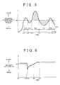
- FIG. 5 illustrates a transition of power-supply electric power that the EPS 1 requires the main power supply 4 to supply in order to execute assist control.
- a first discharging period TD1 indicates a period from time t11 to time t12.
- a first charging period TC1 indicates a period from time t12 to time t13.
- a second discharging period TD2 indicates a period from time t13 to time t14.
- a second charging period TC2 indicates a period from time t14 to time t15.
- a third discharging period TD3 indicates a period from time t15 to time t16.
- a third charging period TC3 indicates a period from time t16 to time t17.
- power-supply electric power PS actual power-supply electric power supplied from the main power supply 4 to the EPS 1 is referred to as power-supply electric power PS.
- the power-supply electric power PS is calculated by the power supply management unit 32 based on the battery current IB detected by the current sensor 42.
- the control device 30 changes the connection mode to the first connection mode, the second connection mode, or the third connection mode, based on the relationship between the power-supply electric power PS and a charging and discharging threshold KE. More specifically, when the power-supply electric power PS is less than the charging and discharging threshold KE, that is, when the capacitor 45 is fully charged in the first charging period TC1, the second charging period TC2, and the third charging period TC3, the control device 30 sets the connection mode to the first connection mode. When the capacitor 45 is not fully charged in the first charging period TC1, the second charging period TC2, and the third charging period TC3, the control device 30 sets the connection mode to the third connection mode.
- the control device 30 sets the connection mode to the second connection mode.
- the power-supply electric power PS is equal to or greater than the charging and discharging threshold KE, that is, in the first discharging period TD1, the second discharging period TD2, and the third discharging period TD3, the control device 30 sets the connection mode to the second connection mode.
- the power-supply electric power PS is equal to or greater than the charging and discharging threshold KE, for example, in a period from time t11, t13, or t15, in which the connection mode is changed to the second connection mode.
- the control device 30 changes the connection mode to the first connection mode, the second connection mode, or the third connection mode, the peak of the power-supply electric power PS (the battery current IB) is restricted at the charging and discharging threshold KE (peak-cut). Consequently, a load on the main power supply 4 is reduced.
- FIG. 6 illustrates a transition of the voltage of the main power supply 4 (hereinafter referred to as a battery voltage VB) in a case where the vehicle is switched from the state where stop-start (idling reduction) is executed to the state where stop-start is cancelled.
- stop-start is executed in the vehicle in a period from time t21 to time t22, and the stop-start is cancelled at time t22. That is, in the vehicle, the alternator 4B is stopped in the period from time t21 to time t22. Therefore, the battery voltage VB is the voltage of the in-vehicle battery 4A in the period from time t21 to time t22.
- driving of the starter motor 5 is started at time t22.
- the alternator 4B of the main power supply 4 In the vehicle, after time t23, the alternator 4B of the main power supply 4 generates electric power as the crankshaft is rotated by the driving of the starter motor 5. The electric power is supplied from the alternator 4B to the in-vehicle battery 4A of the main power supply 4.
- the electric power from the in-vehicle battery 4A is consumed by the driving of the starter motor 5. Because the internal combustion engine is stopped at time t22, the alternator 4B does not supply electric power to the in-vehicle battery 4A. Accordingly, the battery voltage VB abruptly decreases in a period from time t22 to time t23. After time t23, the electric power is supplied from the alternator 4B to the in-vehicle battery 4A, so that the voltage of the in-vehicle battery 4A is boosted as time passes from time t23. After time t25, the voltage of the main power supply 4 is constant. Note that, in the following description, the period from time t22 to time t23 is referred to as a voltage drop period.
- the voltage of the in-vehicle battery 4A decreases in the voltage drop period, the voltage applied to auxiliaries (not shown) for driving an air conditioner and acoustic equipment of the vehicle decreases. Therefore, there is a possibility that the electric power for driving the auxiliaries will not be supplied sufficiently from the in-vehicle battery 4A.
- a booster circuit such as a DC-DC converter may be added to driving circuits (not shown) for driving the auxiliaries.
- the booster circuit is added to the driving circuit of each auxiliary, the number of components of each auxiliary increases, resulting in cost increase.
- the EPS 1 is configured such that, in the voltage drop period, that is, when the starter motor 5 is driven, the control device 30 executes connection mode setting control for setting the connection mode to the fourth connection mode.
- the electric power is supplied from the capacitor 45 to the in-vehicle battery 4A. This suppresses an abrupt decrease in the battery voltage VB. Accordingly, a decrease in the voltage to be applied to each auxiliary is suppressed, so that sufficient electric power is supplied to each auxiliary without adding any booster circuit to each auxiliary.
- connection mode After the connection mode is set to the fourth connection mode, in the EPS 1, the fourth connection mode is maintained until the battery voltage VB reaches a reference value KX.
- the connection mode is changed from the fourth connection mode to the third connection mode, in the EPS 1.
- the capacitor 45 is charged.
- the reference value KX indicates a battery voltage VB at which required electric power can be supplied to the auxiliaries.
- the reference value KX is set in advance through testing or the like.
- connection mode setting control With reference to FIG. 7 , a process of the connection mode setting control will be described. Note that in the following description with reference to FIG. 7 , the components related to the EPS 1, to which the reference symbols are assigned, indicate the components illustrated in FIG. 1 or FIG. 2 .
- the connection mode setting control is executed repeatedly at predetermined intervals.
- connection mode setting control the control device 30 sets the connection mode to one of the first to fourth connection modes in corresponding one of step S21 to S24 based on a determination in the steps S11 to S13.
- step S11 the control device 30 determines whether the power-supply electric power PS is equal to or greater than the charging and discharging threshold KE.
- step S12 the control device 30 determines whether the capacitor 45 is fully charged.
- the power supply management unit 32 of the control device 30 calculates the output voltage V2 based on an output signal from the voltage sensor 47. When the output voltage V2 is equal to or greater than a threshold corresponding to the full charge of the capacitor 45, the power supply management unit 32 determines that the capacitor 45 is fully charged. When the output voltage V2 is smaller than the threshold, the power supply management unit 32 determines that the capacitor 45 is not fully charged. Note that the threshold is set in advance on the basis of the type of the capacitor 45.
- step S13 the control device 30 determines whether the starter motor 5 is being driven.
- the control device 30 receives a signal indicating the driving state of the starter motor 5 from a control device (not shown) of the vehicle, for example, via a CAN communication.
- a control device not shown
- self-starter driving signal SSD a signal indicating that the starter motor 5 is being driven
- the control device 30 determines that the starter motor 5 is being driven.
- the control device 30 has not received the self-starter driving signal SSD, the control device 30 determines that the starter motor 5 is in a stopped state.
- step S11 the control device 30 sets the connection mode to the second connection mode, in step S21. If a negative determination is made in each of step S11 and step S12, the control device 30 sets the connection mode to the third connection mode, in step S22.
- step S11 If a negative determination is made in step S11, an affirmative determination is made in step S12, and an affirmative determination is made in step S13, the control device 30 sets the connection mode to the fourth connection mode, in step S23.
- step S11 If a negative determination is made in step S11, an affirmative determination is made in step S12, and a negative determination is made in step S13, the control device 30 sets the connection mode to the first connection mode, in step S24.
- the EPS 1 according to the present embodiment produces the following advantageous effects.
- the EPS 1 includes the switching circuit 46 capable of switching the connection mode to a mode in which the auxiliary power supply device 40 and the main power supply 4 are connected in parallel to each other. With this configuration, in the EPS 1, the electric power can be supplied from the capacitor 45 to the in-vehicle battery 4A.
- connection mode setting control the connection mode is set to the fourth connection mode at the time of driving the starter motor 5, in the EPS 1.
- connection mode setting control the connection mode is set to the second connection mode in the EPS 1, when the power-supply electric power PS is equal to or greater than the charging and discharging threshold KE.
- the peak of the battery current IB of the power-supply electric power PS is restricted (peak-cut) by boosting the motor drive voltage VMD. This accordingly reduces a load on the main power supply 4.
- the auxiliary power supply device 40 includes the booster circuit 43. With this configuration, the capacitor 45 is charged more quickly in the EPS 1 than in a configuration in which the electric power is supplied from the main power supply 4 to the capacitor 45 by connecting the capacitor 45 in parallel to the main power supply 4, that is, a configuration in which the booster circuit 43 is omitted.
- the electric power steering system according to the invention may be implemented in embodiments other than the aforementioned embodiment. Modified examples of the above-described embodiment will be described as the other embodiments of the electric power steering system according to the invention. Note that the following modified examples may be combined with each other.
- the electric power is supplied from the capacitor 45 to the in-vehicle battery 4A of the main power supply 4 via the boosting coil 43A of the booster circuit 43 when the connection mode is the fourth connection mode.
- the supply passage of the electric power from the capacitor 45 to the in-vehicle battery 4A is not limited to the one described in the aforementioned embodiment.
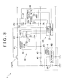
- electric power is supplied from the capacitor 45 to the in-vehicle battery 4A without passing through the booster circuit 43. More specifically, as illustrated in FIG.
- the EPS 1 according to the modified example includes an electric power supply line PL that connects the main power supply 4 to a connecting point P7 with the FET 3 of the booster circuit 43, and a switching element (hereinafter referred to as "FET 7") connected in series with the main power supply 4 and the capacitor 45 via the electric power supply line PL.
- FET 7 switching element
- the FET 7 when the connection mode is the fourth connection mode, the FET 7 is in the on-state, that is, the main power supply 4 and the capacitor 45 are electrically connected to each other via the electric power supply line PL. Accordingly, the electric power is supplied from the capacitor 45 to the in-vehicle battery 4A via the electric power supply line PL.
- the FET 3 is in the off-state when the connection mode is the fourth connection mode.
- the FET 5 when the connection mode is the first connection mode, the FET 5 may be placed in the off-state.
- the crankshaft of the internal combustion engine may be rotated by the alternator 4B instead of the starter motor 5.
- the crankshaft is rotated by the alternator 4B, it is determined whether the alternator 4B is being driven, instead of making a determination on whether the starter motor 5 is being driven, in step S13 in the connection mode setting control.
- connection mode setting control upon reception of the self-starter driving signal SSD, it is determined that the stator motor 5 is being driven, in the EPS 1 according to the aforementioned embodiment.
- the configuration in which it is determined that the starter motor 5 is being driven is not limited to the one described in the aforementioned embodiment.
- it is determined that the starter motor 5 is being driven when the control device 30 receives a driving signal by which a control device of the vehicle controls driving of the starter motor 5.
- connection mode is changed from the fourth connection mode to the third connection mode when the battery voltage VB reaches the reference value KX.
- the timing at which the connection mode is changed from the fourth connection mode to the third connection mode is not limited to the one described in the aforementioned embodiment.
- the connection mode is changed from the fourth connection mode to the third connection mode, when a predetermined period of time has passed after the connection mode is set to the fourth connection mode.
- step S13 in the connection mode setting control it is determined whether the starter motor 5 is being driven, in step S13 in the connection mode setting control.
- the content of step S13 in the connection mode setting control is not limited to the one described in the aforementioned embodiment.
- it is determined whether the rate of drop of the battery voltage VB is equal to or higher than a threshold instead of making a determination on whether the starter motor 5 is being driven, in step S13 in the connection mode setting control.
- the threshold is a voltage drop rate at which there is a possibility that sufficient electric power will not be supplied due to a decrease in the battery voltage VB.
- the threshold is set in advance through testing or the like.
- the EPS 1 according to the aforementioned embodiment may include a plurality of the auxiliary power supply devices 40.
- the auxiliary power supply device 40 according to the aforementioned embodiment includes the capacitor 45 as an auxiliary power supply.
- the configuration of the auxiliary power supply device 40 is not limited to the one described in the aforementioned embodiment.
- an auxiliary power supply device 40 according to a modified example includes a secondary battery such as a lithium ion battery instead of the capacitor 45.
- an electric double layer capacitor is used as the capacitor 45 according to the aforementioned embodiment.
- the type of the capacitor 45 is not limited to the one described in the aforementioned embodiment.
- a capacitor 45 in a modified example a lithium ion capacitor is employed instead of the electric double layer capacitor.
- MOSFETs are employed as the FET 1 and the FET 2.
- the type of the FET 1 and the FET 2 is not limited to the one described in the aforementioned embodiment.
- switching elements having other configurations, such as IGBTs are used as the FET 1 and the FET 2.
- the FET 5 and the FET 6 of the switching circuit 46 may be modified in a similar manner.
- the electric motor 21 according to the aforementioned embodiment has a configuration of a three-phase brushless motor.
- the configuration of the electric motor 21 is not limited to the one described in the aforementioned embodiment.
- an electric motor 21 according to a modified example has a configuration of a motor with brush.
- the EPS 1 according to the aforementioned embodiment has a column-assist type configuration.
- the configuration of the EPS 1 is not limited to the one described in the aforementioned embodiment.
- an EPS 1 in a modified example has a configuration of a pinion assist type, a dual pinion assist type, a rack coaxial type, or a rack parallel type.
Landscapes
- Engineering & Computer Science (AREA)
- Chemical & Material Sciences (AREA)
- Combustion & Propulsion (AREA)
- Transportation (AREA)
- Mechanical Engineering (AREA)
- Steering Control In Accordance With Driving Conditions (AREA)
- Power Steering Mechanism (AREA)
- Electric Propulsion And Braking For Vehicles (AREA)
Abstract
Description
- The invention relates to an electric power steering system including an auxiliary power supply.
- One of the conventional electric power steering system includes an auxiliary power supply device connected in series with a main power supply. The electric power steering system makes a switchover between charging to a capacitor serving as an auxiliary power supply from the main power supply and discharging to a motor driving circuit from the main power supply and the capacitor, based on a charging and discharging threshold changed on the basis of an energy residual amount in the capacitor. Japanese Patent Application Publication No.
2009-166679 JP 2009-166679 A - The conventional electric power steering system is configured such that the capacitor discharges electric power to the motor driving circuit, and is not configured such that the capacitor discharges electric power to the main power supply. Thus, it is not possible to supply electric power to the main power supply from the capacitor.
- One object of the invention is to provide an electric power steering system configured such that an auxiliary power supply device is able to supply electric power to a main power supply.
- An electric power steering system according to an aspect of the invention includes: an electric motor that generates assist torque based on steering torque; a main power supply that supplies electric power to the electric motor; an auxiliary power supply device including an auxiliary power supply connected to the main power supply and capable of discharging electric power to the electric motor; and a control device that controls an operation of the auxiliary power supply device. The control device switches a mode, as a mode of connection between the main power supply and the auxiliary power supply device, among a first supply mode in which the main power supply and the auxiliary power supply are connected in series with each other and a high-potential side of the auxiliary power supply is connected to the electric motor, a second supply mode in which the main power supply and the auxiliary power supply are connected in series with each other and a low-potential side of the auxiliary power supply is connected to the electric motor, and a main power supply charging mode in which the main power supply and the auxiliary power supply are connected in parallel to each other.
- In the above-described electric power steering system, when the connection mode is switched to the main power supply charging mode by the control device, the main power supply and the auxiliary power supply are connected in parallel to each other. Accordingly, when the voltage of the main power supply is lower than the voltage of the auxiliary power supply, electric power can be supplied from the auxiliary power supply to the main power supply, in the electric power steering system.
- In the electric power steering system according to the above-described aspect, when an engine of a vehicle is stopped and a starter that starts the engine is driven, the control device may switch the connection mode to the main power supply charging mode.
- Generally, when an engine of a vehicle is stopped and a starter is driven, the voltage of a main power supply abruptly decreases. In contrast to this, in the electric power steering system according to the above-described aspect, when the engine of the vehicle is stopped and the starter that starts the engine is driven, the control device switches the connection mode to the main power supply charging mode. As a result, the voltage of the main power supply is boosted. Hereby, a drop of the voltage of the main power supply is suppressed.
- In the electric power steering system according to the above-described aspect, when a rate of drop of the voltage of the main power supply is equal to or higher than a threshold, the control device may switch the connection mode to the main power supply charging mode.
- In the above electric power steering system, when the rate of drop of the voltage of the main power supply is equal to or higher than the threshold, the connection mode is switched to the main power supply charging mode by the control device. Thus, the voltage of the main power supply is boosted by the auxiliary power supply, so that a drop of the voltage of the main power supply is suppressed.
- In the electric power steering system according to the above-described aspect, the control device may switch the connection mode to the main power supply charging mode when power-supply electric power consumed by the electric power steering system due to assist control for assisting steering is less than a charging and discharging threshold, which is a reference value for making a switchover between charging from the main power supply to the auxiliary power supply and discharging from the auxiliary power supply to the electric motor.
- In the above electric power steering system, when the power-supply electric power consumed by the electric power steering system is less than the charging and discharging threshold, the connection mode is switched to the main power supply charging mode by the control device. That is, even in a case where the engine of the vehicle is stopped and the starter is driven or even in a case where the rate of drop of the voltage of the main power supply is equal to or higher than the threshold, if the power-supply electric power consumed by the electric power steering system is equal to or greater than the charging and discharging threshold, the control device does not switch the connection mode to the main power supply charging mode. Accordingly, in the above electric power steering system, higher priority is given to supplying electric power from the auxiliary power supply to the electric motor than charging the main power supply with the use of the auxiliary power supply.
- The electric power steering system according to the above-described aspect may further include
a first switching element that makes a switchover between an on-state in which the main power supply and the auxiliary power supply are in a conductive state and an off-state in which the main power supply and the auxiliary power supply are in a non-conductive state;
and a second switching element of which one end is connected to a connecting point between the first switching element and the auxiliary power supply and of which the other end is grounded, the second switching element making a switchover between an on-state in which the connecting point between the first switching element and the auxiliary power supply is in a grounded state and an off-state in which the connecting point is not in the grounded state.
In the first supply mode and the second supply mode, the control device may place the first switching element in the on-state and the second switching element in the off-state. In the main power supply charging mode, the control device may place the first switching element in the off-state and the second switching element in the on-state. - The electric power steering system is configured such that the auxiliary power supply is able to supply electric power to the main power supply.
- The foregoing and further features and advantages of the invention will become apparent from the following description of example embodiments with reference to the accompanying drawings, wherein like numerals are used to represent like elements and wherein:
-
FIG. 1 is a schematic diagram illustrating the configuration of an electric power steering system according to an embodiment of the invention; -
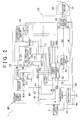
FIG. 2 is a circuit diagram illustrating the circuit configuration of the electric power steering system according to the embodiment; -
FIG. 3 is a table illustrating the relationship between the connection modes of the electric power steering system and the states of each switching element according to the embodiment; -
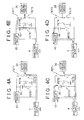
FIG. 4A is a circuit diagram illustrating the simplified circuit configuration of the electric power steering system according to the embodiment, and illustrating the circuit configuration in a first connection mode; -
FIG. 4B is a circuit diagram illustrating the simplified circuit configuration of the electric power steering system according to the embodiment, and illustrating a circuit configuration in a second connection mode; -
FIG. 4C is a circuit diagram illustrating the simplified circuit configuration of the electric power steering system according to the embodiment, and illustrating a circuit configuration in a third connection mode; -
FIG. 4D is a circuit diagram illustrating the simplified circuit configuration of the electric power steering system according to the embodiment, and illustrating a circuit configuration in a fourth connection mode; -
FIG. 5 is a graph related to the electric power steering system according to the embodiment, and illustrating a transition of a required power-supply electric power; -
FIG. 6 is a graph related to the electric power steering system according to the embodiment, and illustrating a transition of the battery voltage; -
FIG. 7 is a flowchart illustrating the procedure of a connection mode setting control executed by a control device according to the embodiment; and -
FIG. 8 is a circuit diagram illustrating the circuit configuration of an electric power steering system according to another embodiment of the invention. - With reference to
FIG. 1 , the configuration of an electric power steering system 1 (hereinafter, referred to as "EPS 1") according to an embodiment of the invention will be described below. TheEPS 1 includes an EPSmain body 10, anassist device 20, acontrol device 30, an auxiliarypower supply device 40, atorque sensor 50, and avehicle speed sensor 60. TheEPS 1 is configured such that electric power is supplied to theassist device 20 from amain power supply 4 and the auxiliarypower supply device 40 via thecontrol device 30. TheEPS 1 assists an operation of a steering wheel 2 with the use of theassist device 20, based on signals output from thetorque sensor 50 and thevehicle speed sensor 60. - The EPS
main body 10 includes acolumn shaft 11, anintermediate shaft 12, apinion shaft 13, arack shaft 14, a rack-and-pinion mechanism 15, and twotie rods 16. The EPSmain body 10 rotates thecolumn shaft 11, theintermediate shaft 12, and thepinion shaft 13 together with each other in response to the rotation of the steering wheel 2. The EPSmain body 10 changes the steered angle ofwheels 3 by causing therack shaft 14 to make a reciprocating motion with the rotation of thepinion shaft 13. - The rack-and-
pinion mechanism 15 has a configuration in which a pinion gear (not shown) of thepinion shaft 13 and a rack gear (not shown) of therack shaft 14 mesh with each other. The rack-and-pinion mechanism 15 converts the rotation of thepinion shaft 13 into a reciprocating motion of therack shaft 14 due to the mesh between the pinion gear and the rack gear. - The
assist device 20 includes anelectric motor 21, which is a three-phase brushless motor, and aspeed reduction mechanism 22. Theassist device 20 applies, to thecolumn shaft 11, a force (hereinafter referred to as "assist torque") for rotating thecolumn shaft 11 by transmitting the rotation of theelectric motor 21 to thecolumn shaft 11 via thespeed reduction mechanism 22. As described above, theEPS 1 according to the present embodiment has a column-assist type configuration. - The output level of a voltage signal output from the
torque sensor 50 changes on the basis of the torsion of atorsion bar 51 connected to an intermediate portion of thecolumn shaft 11, that is, the magnitude of a torque (hereinafter, referred to as "steering torque τ") applied to thecolumn shaft 11 in response to the operation of the steering wheel 2. Thetorque sensor 50 outputs the voltage signal to thecontrol device 30. - The output level of a voltage signal output from the
vehicle speed sensor 60 changes on the basis of the rotational speed of a drive shaft (not shown) of a vehicle, that is, a vehicle travelling speed (hereinafter referred to as "vehicle speed V"). Thevehicle speed sensor 60 outputs the voltage signal to thecontrol device 30. - The
control device 30 calculates the magnitude of the steering torque τ and the direction thereof based on the voltage signal from thetorque sensor 50. Thecontrol device 30 calculates the vehicle speed V based on the voltage signal from thevehicle speed sensor 60. Thecontrol device 30 executes assist control for assisting steering. More specifically, thecontrol device 30 calculates a target assist torque based on the steering torque τ and the vehicle speed V. Then, thecontrol device 30 controls the operation of theelectric motor 21 by supplying theelectric motor 21 with electric power corresponding to the target assist torque. Theelectric motor 21 generates an assist torque based on the target assist torque. - With reference to
FIG. 2 , the detailed configurations of themain power supply 4, thecontrol device 30, and the auxiliarypower supply device 40 will be described. Themain power supply 4 includes an in-vehicle battery 4A and analternator 4B. Themain power supply 4 has a configuration in which the in-vehicle battery 4A and thealternator 4B are connected in parallel to each other. One end of themain power supply 4 is connected in series with the auxiliarypower supply device 40 and astarter motor 5, and the other end thereof is grounded. Note that thestarter motor 5 corresponds to a starter. - The
alternator 4B generates electric power when an output shaft of thealternator 4B rotates with the rotation of a crankshaft (not shown) of an internal combustion engine (not shown) of the vehicle. Thealternator 4B supplies the electric power thus generated to the in-vehicle battery 4A. When the electric power is supplied from themain power supply 4 to thestarter motor 5 in order to start the internal combustion engine, thestarter motor 5 rotates the crankshaft. - The
control device 30 includes amicrocomputer 31, amotor driving circuit 34, acurrent sensor 35, and avoltage sensor 36. Thecontrol device 30 controls an operation of themotor driving circuit 34 and an operation of the auxiliarypower supply device 40 with the use of themicrocomputer 31. - The output level of a voltage signal output from the
current sensor 35 changes on the basis of the magnitude of actual current (hereinafter referred to as "motor current IM") supplied to theelectric motor 21. Thecurrent sensor 35 outputs the voltage signal to amotor control unit 33 of themicrocomputer 31. - The output level of a voltage signal output from the
voltage sensor 36 changes on the basis of the magnitude of the voltage between the auxiliarypower supply device 40 and themotor driving circuit 34, that is, the voltage that is applied to the motor driving circuit 34 (hereinafter, referred to as "motor drive voltage VMD"). Thevoltage sensor 36 outputs the voltage signal to a powersupply management unit 32 of themicrocomputer 31. - The
microcomputer 31 includes the powersupply management unit 32 and themotor control unit 33. Themicrocomputer 31 controls the charging and discharging operation of the auxiliarypower supply device 40 with the use of the powersupply management unit 32. Themicrocomputer 31 controls the operation of themotor driving circuit 34 with the use of themotor control unit 33. - The power
supply management unit 32 controls the operations of arelay 41, abooster circuit 43, a charging and dischargingcircuit 44, and aswitching circuit 46 of the auxiliarypower supply device 40. The powersupply management unit 32 outputs, to therelay 41, a relay signal SR for controlling the operation of therelay 41. The powersupply management unit 32 outputs, to thebooster circuit 43, booster signals SB1, SB2 for controlling the operation of thebooster circuit 43. The powersupply management unit 32 outputs, to the charging and dischargingcircuit 44, charging and discharging signals SCD1, SCD2 for controlling the operation of the charging and dischargingcircuit 44. The powersupply management unit 32 outputs, to the switchingcircuit 46, switching signals SS1, SS2 for controlling the operation of the switchingcircuit 46. - The
motor control unit 33 calculates the target assist torque based on the steering torque τ and the vehicle speed V. Themotor control unit 33 executes current feedback control such that the motor current IM coincides with a current command value corresponding to the target assist torque. Themotor control unit 33 outputs, to themotor driving circuit 34, a motor control signal SM generated through execution of the current feedback control. Note that the motor control signal SM functions also as a signal for executing PWM control on themotor driving circuit 34. Further, the target assist torque increases as the absolute value of the steering torque τ increases or as the absolute value of the vehicle speed V decreases. - The
motor driving circuit 34 has a known configuration in which two switching elements (MOSFETs) are connected in series with each of the phases of theelectric motor 21. In themotor driving circuit 34, the two switching elements of each of the phases of themotor driving circuit 34 are alternately switched between the on-state and the off-state based on the motor control signal SM from themotor control unit 33. Themotor driving circuit 34 applies the motor drive voltage VMD to theelectric motor 21, through PWM driving, on the basis of the switching of each of the switching elements between the on-state and the off-state. - The auxiliary
power supply device 40 is formed separately from themain power supply 4. The auxiliarypower supply device 40 includes therelay 41, acurrent sensor 42, thebooster circuit 43, the charging and dischargingcircuit 44, and acapacitor 45 as an auxiliary power supply, the switching circuit, 46, and avoltage sensor 47. The auxiliarypower supply device 40 is capable of discharging electric power to theelectric motor 21 and is capable of discharging electric power to themain power supply 4 with the use of thecapacitor 45. - The
relay 41 is arranged between themain power supply 4 and thebooster circuit 43. Therelay 41 switches the power supply state between the on-state in which themain power supply 4 supplies electric power to themotor driving circuit 34 and the off-state in which themain power supply 4 does not supply electric power to themotor driving circuit 34. - The
current sensor 42 is arranged between therelay 41 and thebooster circuit 43. The output level of a voltage signal output from thecurrent sensor 42 changes on the basis of the magnitude of a current (hereinafter referred to "battery current IB") output from themain power supply 4. Thecurrent sensor 42 outputs the voltage signal to the powersupply management unit 32. - The
booster circuit 43 boosts the output voltage based on the voltage (battery voltage) of themain power supply 4, that is, the output voltage at a connecting point P1 between themain power supply 4 and the booster circuit 43 (hereinafter referred to as "output voltage V1"), and applies the boosted output voltage to a connecting point P2, which is an positive terminal of thecapacitor 45, thereby charging thecapacitor 45. - The
booster circuit 43 includes a pair of switching elements (hereinafter referred to as "aFET 3 and aFET 4"), and a boostingcoil 43A. Thebooster circuit 43 has a configuration in which theFET 3 and theFET 4 are connected in series with each other. Thebooster circuit 43 has a configuration in which one end of the boostingcoil 43A is connected to a connecting point P3 between theFET 3 and theFET 4. Thebooster circuit 43 has a configuration in which the output voltage V1 is applied to the other end of the boostingcoil 43A. - As the
FET 3 and theFET 4, MOSFETs are employed. One end of theFET 3 on the upper side is connected to the positive terminal (the connecting point P2) of thecapacitor 45. One end of theFET 4 on the lower side is grounded. TheFET 3 and theFET 4 are switched between the on-state and the off-state based on the booster signals SB1, SB2 from the powersupply management unit 32, respectively. - The charging and discharging
circuit 44 is connected in parallel with thebooster circuit 43. The charging and dischargingcircuit 44 includes a pair of switching elements (hereinafter referred to as "aFET 1 and a FET 2"). The charging and dischargingcircuit 44 has a configuration in which theFET 1 and the FET 2 are connected in series with each other. The charging and dischargingcircuit 44 is connected to themotor driving circuit 34 at a connecting point P4 between theFET 1 and FET 2. - As the
FET 1 and the FET 2, MOSFETs are employed. One end of theFET 1 on the upper side is connected to the positive terminal (the connecting point P2) of thecapacitor 45. One end of the FET 2 on the lower side is connected to themain power supply 4 via therelay 41 and thecurrent sensor 42. TheFET 1 and FET 2 are periodically switched between the on-state, which is a conductive state, and the off-state, which is a nonconductive state, based on the charging and discharging signals SCD1, SCD2 from the powersupply management unit 32, respectively. In the on-state, theFET 1 is in a state where electric power can be discharged from the capacitor 45 (the auxiliary power supply device 40) to the motor driving circuit 34 (the electric motor 21). In the off-state, theFET 1 is in a state where electric power cannot be discharged from the capacitor 45 (the auxiliary power supply device 40) to the motor driving circuit 34 (the electric motor 21). In the on-state, the FET 2 is in a state where electric power can be supplied from themain power supply 4 to themotor driving circuit 34 via the FET 2. In the off-state, the FET 2 is in a state where electric power cannot be supplied from themain power supply 4 to themotor driving circuit 34 via the FET 2. - Between the
booster circuit 43 and the charging and dischargingcircuit 44, thecapacitor 45 is connected in parallel with thebooster circuit 43 and the charging and dischargingcircuit 44. One end of thecapacitor 45 is connected to the connecting point P2, and the other end of thecapacitor 45 is connected to the switchingcircuit 46. In thecapacitor 45, the connecting point P2-side is a high-potential side, and the switching circuit 46-side is a low-potential side. As thecapacitor 45, an electric double layer capacitor is used. - The
voltage sensor 47 is connected in parallel to thecapacitor 45. Thevoltage sensor 47 outputs a signal corresponding to the voltage of the capacitor 45 (hereinafter referred to as "output voltage V2") to the powersupply management unit 32. The switchingcircuit 46 is located between thecapacitor 45 and themain power supply 4. The switchingcircuit 46 includes two switching elements (hereinafter referred to "aFET 5 and a FET 6"). The switchingcircuit 46 changes the mode of connection between thecapacitor 45 and themain power supply 4. Note that theFET 5 corresponds to a first switching element. The FET 6 corresponds to a second switching element. - The
FET 5 is connected in series with themain power supply 4 and thecapacitor 45. One end of theFET 5 is connected to thecapacitor 45, and the other end of theFET 5 is connected to a connecting point P5 between thecurrent sensor 42 and the FET 2. When theFET 5 is in the on-state, themain power supply 4 and thecapacitor 45 are brought into a conductive state via theFET 5. When theFET 5 is in the off-state, themain power supply 4 and thecapacitor 45 are brought into a non-conductive state (conduction between themain power supply 4 and thecapacitor 45 via theFET 5 is interrupted). - The FET 6 is located on an electric power supply line that branches off from a connecting point P6 between the
FET 5 and thecapacitor 45. One end of the FET 6 is connected in series with the connecting point P6, and the other end of the FET 6 is grounded. When the FET 6 is in the on-state, the connecting point P6 is grounded via the FET 6. When the FET 6 is in the off-state, the connecting point P6 is not grounded via the FET 6. - The operation of the
relay 41 will be described below. Therelay 41 is switched between the on-state and the off-state based on the relay signal SR from the powersupply management unit 32. When an ignition switch (not shown) of the vehicle is turned on, therelay 41 is switched from the off-state to the on-state. When the ignition switch is turned off, therelay 41 is switched from the on-state to the off-state. - The operation of the
booster circuit 43 will be described below. Thebooster circuit 43 applies, to the positive terminal (the connecting point P2) of thecapacitor 45, a boosted voltage V3 generated when theFET 4 on the lower side is switched from the on-state to the off-state. In thebooster circuit 43, theFET 4 becomes conductive in the on-state, so that one end of the boosting coil 43C is grounded. Then, thebooster circuit 43 superimposes, on the output voltage V1, an induced voltage generated in the boostingcoil 43A when theFET 4 is switched from the off-state to the on-state, and outputs the thus obtained voltage. Note that theFET 3 on the upper side has a function of preventing a current from flowing from the capacitor-45 side to the booster-circuit-43 side (back-flow). - The operation of the charging and discharging
circuit 44 will be described below. The charging and dischargingcircuit 44 switches the power supply mode between a first power supply mode in which thecapacitor 45 can be charged with electric power from themain power supply 4 and a second power supply mode in which thecapacitor 45 can discharge electric power to themotor driving circuit 34, based on a combination of the on-state and the off-state of theFET 1 and the FET 2. Note that theFET 1 and the FET 2 are controlled by the powersupply management unit 32 so as not to be in the on-state at the same time. - In the first power supply mode, the
FET 1 on the upper side is in the off-state and the FET 2 on the lower side is in the on-state. In the first power supply mode, the battery current IB from themain power supply 4 is supplied to thecapacitor 45 and is supplied to themotor driving circuit 34 via the FET 2. In the first power supply mode, theFET 1 is in the off-state, so that thecapacitor 45 does not discharge electric power to themotor driving circuit 34. In the first power supply mode, the motor drive voltage VMD is the output voltage V1. - In the second power supply mode, the
FET 1 on the upper side is in the on-state and the FET 2 on the lower side is in the off-state. In the second power supply mode, themain power supply 4 and the auxiliary power supply device 40 (the capacitor 45) are connected in series with each other. In the second power supply mode, themotor driving circuit 34 is supplied with current discharged from thecapacitor 45 in addition to the electric power from themain power supply 4. In the second power supply mode, the motor drive voltage VMD is the sum of the output voltage V1 and the output voltage V2 from thecapacitor 45. - The operation of the switching
circuit 46 will be described below. The switchingcircuit 46 makes a switchover between a first switching mode in which themain power supply 4 and thecapacitor 45 are connected in series with each other and a second switching mode in which themain power supply 4 and thecapacitor 45 are connected in parallel to each other, based on a combination of the on-state and the off-state of theFET 5 and the FET 6. TheFET 5 and the FET 6 are controlled by the powersupply management unit 32 so as not to be in the on-state at the same time. - In the first switching mode, the
FET 5 is in the on-state and the FET 6 is in the off-state. In the first switching mode, discharging from thecapacitor 45 to themain power supply 4 is interrupted by the switchingcircuit 46.
In the second switching mode, theFET 5 is in the off-state and the FET 6 is in the on-state. In the second switching mode, discharging from thecapacitor 45 to themain power supply 4 is allowed by the switchingcircuit 46. - With reference to
FIG. 3 andFIG. 4 , the mode of connection between themain power supply 4 and the auxiliary power supply device 40 (hereinafter referred to as "connection mode") will be described below.FIG. 4 illustrates the simplified circuit configuration of theEPS 1 and themain power supply 4. In the following description, the components related to the EPS 1 (not shown) indicate the components illustrated inFIG. 2 . - The
EPS 1 has a first connection mode, a second connection mode, a third connection mode, and a fourth connection mode as the connection modes. The second connection mode corresponds to a first supply mode. The first connection mode and the third connection mode correspond to a second supply mode. The fourth connection mode corresponds to a main power supply charging mode. - The first connection mode is set when the
capacitor 45 is fully charged and when electric power is supplied from themain power supply 4 to themotor driving circuit 34. In the first connection mode, thebooster circuit 43 is in a stopped state, the charging and dischargingcircuit 44 is in the first power supply mode, and the switchingcircuit 46 is in the first switching mode. More specifically, as illustrated inFIG. 3 , in the first connection mode, theFET 1 is in the off-state, the FET 2 is in the on-state, theFET 3 is in the off-state, theFET 4 is in the off-state, theFET 5 is in the on-state, and the FET 6 is in the off-state. - As illustrated in
FIG. 4A , in the first connection mode, the electric power is supplied from themain power supply 4 to themotor driving circuit 34 via the FET 2. In the first connection mode, the electric power is not supplied from themain power supply 4 to thecapacitor 45 because thecapacitor 45 is fully charged. In the first connection mode, the motor drive voltage VMD is the output voltage V1. - The second connection mode is set when the electric power is supplied from the
main power supply 4 and thecapacitor 45 to themotor driving circuit 34. In the second connection mode, thebooster circuit 43 is in the stopped state, the charging and dischargingcircuit 44 is in the second power supply mode, and the switchingcircuit 46 is in the first switching mode. More specifically, as illustrated inFIG. 3 , in the second connection mode, theFET 1 is in the on-state, the FET 2 is in the off-state, theFET 3 is in the off-state, theFET 4 is in the off-state, theFET 5 is in the on-state, and the FET 6 is in the off-state. - As illustrated in
FIG. 4B , in the second connection mode, the electric power from themain power supply 4 passes through thecapacitor 45 via theFET 5. At this time, the output voltage V2 of thecapacitor 45 is superimposed on the output voltage V1 from themain power supply 4. The electric power from themain power supply 4 is then supplied to themotor driving circuit 34 via theFET 1. In the second power supply mode, the motor drive voltage VMD is the sum of the output voltage V1 and the output voltage V2. - The third connection mode is set when the
capacitor 45 is charged with the electric power from themain power supply 4 and the electric power from themain power supply 4 is supplied to themotor driving circuit 34. In the third connection mode, thebooster circuit 43 is in a driving state, the charging and dischargingcircuit 44 is in the first power supply mode, and the switchingcircuit 46 is in the first switching mode. More specifically, as illustrated inFIG. 3 , in the third connection mode, theFET 1 is in the off-state, the FET 2 is in the on-state, theFET 4 is in a PWM driving state, theFET 3 is in a state where PWM driving is executed on theFET 3 such that theFET 3 and theFET 4 are not in the on-state at the same time, theFET 5 is in the on-state, and the FET 6 is in the off-state. - As illustrated in
FIG. 4C , in the third connection mode, the electric power from themain power supply 4 is supplied to thecapacitor 45 via thebooster circuit 43. At this time, the output voltage V1 is boosted in thebooster circuit 43, and the boosted voltage is applied to thecapacitor 45. Therefore, the charging rate at which thecapacitor 45 is charged is higher than that in the configuration in which themain power supply 4 and thecapacitor 45 are connected in parallel to each other, that is, the configuration in which thebooster circuit 43 is omitted. This reduces the time required to fully charge thecapacitor 45. Further, the electric power from themain power supply 4 is supplied to themotor driving circuit 34 via the FET 2. In the third connection mode, the motor drive voltage VMD is the output voltage V1. - The fourth connection mode is set when the
main power supply 4 is charged with electric power from thecapacitor 45. In the fourth connection mode, thebooster circuit 43 is in the stopped state, thecapacitor 45 and themain power supply 4 are in the conductive state, the charging and dischargingcircuit 44 is in the first power supply mode, and the switchingcircuit 46 is in the second switching mode. More specifically, as illustrated inFIG. 3 , in the fourth connection mode, theFET 1 is in the off-state, the FET 2 is in the on-state, theFET 3 is in the on-state, theFET 4 is in the off-state, theFET 5 is in the off-state, and the FET 6 is in the on-state. - As illustrated in
FIG. 4D , themain power supply 4 and thecapacitor 45 are connected in parallel to each other in the fourth connection mode. Accordingly, when the voltage of thecapacitor 45 is higher than the voltage of themain power supply 4, the electric power from thecapacitor 45 is supplied to themain power supply 4 via thebooster circuit 43. Because theFET 5 is in the off-state and theFET 1 is in the off-state, the electric power is not supplied from thecapacitor 45 to themotor driving circuit 34. - With reference to
FIG. 5 and FIG. 6 , the control for changing the connection mode, which is executed by thecontrol device 30, will be described below. In the following description with reference toFIG. 5 and FIG. 6 , the components related to theEPS 1 to which the reference symbols are assigned indicate the components illustrated inFIG. 1 orFIG. 2 . -
FIG. 5 illustrates a transition of power-supply electric power that theEPS 1 requires themain power supply 4 to supply in order to execute assist control. InFIG. 5 , a first discharging period TD1 indicates a period from time t11 to time t12. A first charging period TC1 indicates a period from time t12 to time t13. A second discharging period TD2 indicates a period from time t13 to time t14. A second charging period TC2 indicates a period from time t14 to time t15. A third discharging period TD3 indicates a period from time t15 to time t16. A third charging period TC3 indicates a period from time t16 to time t17. - Hereinafter, actual power-supply electric power supplied from the
main power supply 4 to theEPS 1 is referred to as power-supply electric power PS. The power-supply electric power PS is calculated by the powersupply management unit 32 based on the battery current IB detected by thecurrent sensor 42. - The
control device 30 changes the connection mode to the first connection mode, the second connection mode, or the third connection mode, based on the relationship between the power-supply electric power PS and a charging and discharging threshold KE. More specifically, when the power-supply electric power PS is less than the charging and discharging threshold KE, that is, when thecapacitor 45 is fully charged in the first charging period TC1, the second charging period TC2, and the third charging period TC3, thecontrol device 30 sets the connection mode to the first connection mode. When thecapacitor 45 is not fully charged in the first charging period TC1, the second charging period TC2, and the third charging period TC3, thecontrol device 30 sets the connection mode to the third connection mode. When the power-supply electric power PS is equal to or greater than the charging and discharging threshold KE, that is, in the first discharging period TD1, the second discharging period TD2, and the third discharging period TD3, thecontrol device 30 sets the connection mode to the second connection mode. Note that examples of a case where the power-supply electric power PS is equal to or greater than the charging and discharging threshold KE include a case where a driver performs stationary steering (steering operation performed while a vehicle is not travelling) of the steering wheel 2 while the vehicle is being placed in a garage or the vehicle is being parked. Further, the power-supply electric power PS is equal to or greater than the charging and discharging threshold KE, for example, in a period from time t11, t13, or t15, in which the connection mode is changed to the second connection mode. - When the
control device 30 changes the connection mode to the first connection mode, the second connection mode, or the third connection mode, the peak of the power-supply electric power PS (the battery current IB) is restricted at the charging and discharging threshold KE (peak-cut). Consequently, a load on themain power supply 4 is reduced. -
FIG. 6 illustrates a transition of the voltage of the main power supply 4 (hereinafter referred to as a battery voltage VB) in a case where the vehicle is switched from the state where stop-start (idling reduction) is executed to the state where stop-start is cancelled. InFIG. 6 , stop-start is executed in the vehicle in a period from time t21 to time t22, and the stop-start is cancelled at time t22. That is, in the vehicle, thealternator 4B is stopped in the period from time t21 to time t22. Therefore, the battery voltage VB is the voltage of the in-vehicle battery 4A in the period from time t21 to time t22. In the vehicle, driving of thestarter motor 5 is started at time t22. In the vehicle, after time t23, thealternator 4B of themain power supply 4 generates electric power as the crankshaft is rotated by the driving of thestarter motor 5. The electric power is supplied from thealternator 4B to the in-vehicle battery 4A of themain power supply 4. - At time t22, the electric power from the in-
vehicle battery 4A is consumed by the driving of thestarter motor 5. Because the internal combustion engine is stopped at time t22, thealternator 4B does not supply electric power to the in-vehicle battery 4A. Accordingly, the battery voltage VB abruptly decreases in a period from time t22 to time t23. After time t23, the electric power is supplied from thealternator 4B to the in-vehicle battery 4A, so that the voltage of the in-vehicle battery 4A is boosted as time passes from time t23. After time t25, the voltage of themain power supply 4 is constant. Note that, in the following description, the period from time t22 to time t23 is referred to as a voltage drop period. - Because the voltage of the in-
vehicle battery 4A decreases in the voltage drop period, the voltage applied to auxiliaries (not shown) for driving an air conditioner and acoustic equipment of the vehicle decreases. Therefore, there is a possibility that the electric power for driving the auxiliaries will not be supplied sufficiently from the in-vehicle battery 4A. - In order to deal with this problem, a booster circuit such as a DC-DC converter may be added to driving circuits (not shown) for driving the auxiliaries. However, in a case where the booster circuit is added to the driving circuit of each auxiliary, the number of components of each auxiliary increases, resulting in cost increase.
- The
EPS 1 according to the present embodiment is configured such that, in the voltage drop period, that is, when thestarter motor 5 is driven, thecontrol device 30 executes connection mode setting control for setting the connection mode to the fourth connection mode. In the voltage drop period, the electric power is supplied from thecapacitor 45 to the in-vehicle battery 4A. This suppresses an abrupt decrease in the battery voltage VB. Accordingly, a decrease in the voltage to be applied to each auxiliary is suppressed, so that sufficient electric power is supplied to each auxiliary without adding any booster circuit to each auxiliary. - After the connection mode is set to the fourth connection mode, in the
EPS 1, the fourth connection mode is maintained until the battery voltage VB reaches a reference value KX. When the battery voltage VB reaches the reference value KX (at time t24), the connection mode is changed from the fourth connection mode to the third connection mode, in theEPS 1. Thus, in theEPS 1, thecapacitor 45 is charged. The reference value KX indicates a battery voltage VB at which required electric power can be supplied to the auxiliaries. The reference value KX is set in advance through testing or the like. - With reference to
FIG. 7 , a process of the connection mode setting control will be described. Note that in the following description with reference toFIG. 7 , the components related to theEPS 1, to which the reference symbols are assigned, indicate the components illustrated inFIG. 1 orFIG. 2 . The connection mode setting control is executed repeatedly at predetermined intervals. - In the connection mode setting control, the
control device 30 sets the connection mode to one of the first to fourth connection modes in corresponding one of step S21 to S24 based on a determination in the steps S11 to S13. - In step S11, the
control device 30 determines whether the power-supply electric power PS is equal to or greater than the charging and discharging threshold KE. In step S12, thecontrol device 30 determines whether thecapacitor 45 is fully charged. The powersupply management unit 32 of thecontrol device 30 calculates the output voltage V2 based on an output signal from thevoltage sensor 47. When the output voltage V2 is equal to or greater than a threshold corresponding to the full charge of thecapacitor 45, the powersupply management unit 32 determines that thecapacitor 45 is fully charged. When the output voltage V2 is smaller than the threshold, the powersupply management unit 32 determines that thecapacitor 45 is not fully charged. Note that the threshold is set in advance on the basis of the type of thecapacitor 45. - In step S13, the
control device 30 determines whether thestarter motor 5 is being driven. Thecontrol device 30 receives a signal indicating the driving state of thestarter motor 5 from a control device (not shown) of the vehicle, for example, via a CAN communication. When thecontrol device 30 receives a signal indicating that thestarter motor 5 is being driven (hereinafter referred to as "self-starter driving signal SSD"), thecontrol device 30 determines that thestarter motor 5 is being driven. When thecontrol device 30 has not received the self-starter driving signal SSD, thecontrol device 30 determines that thestarter motor 5 is in a stopped state. - If an affirmative determination is made in step S11, the
control device 30 sets the connection mode to the second connection mode, in step S21. If a negative determination is made in each of step S11 and step S12, thecontrol device 30 sets the connection mode to the third connection mode, in step S22. - If a negative determination is made in step S11, an affirmative determination is made in step S12, and an affirmative determination is made in step S13, the
control device 30 sets the connection mode to the fourth connection mode, in step S23. - If a negative determination is made in step S11, an affirmative determination is made in step S12, and a negative determination is made in step S13, the
control device 30 sets the connection mode to the first connection mode, in step S24. - The
EPS 1 according to the present embodiment produces the following advantageous effects. TheEPS 1 includes the switchingcircuit 46 capable of switching the connection mode to a mode in which the auxiliarypower supply device 40 and themain power supply 4 are connected in parallel to each other. With this configuration, in theEPS 1, the electric power can be supplied from thecapacitor 45 to the in-vehicle battery 4A. - In the connection mode setting control, the connection mode is set to the fourth connection mode at the time of driving the
starter motor 5, in theEPS 1. With this configuration, it is possible to suppress an abrupt decrease in the battery voltage VB, which would be caused due to the driving of thestarter motor 5. Accordingly, required electric power is supplied to each auxiliary even if a booster circuit is not added to each auxiliary. - In the connection mode setting control, the connection mode is set to the second connection mode in the
EPS 1, when the power-supply electric power PS is equal to or greater than the charging and discharging threshold KE. With this configuration, when theEPS 1 requires a large amount of electric power in order to execute, for example, stationary steering, the peak of the battery current IB of the power-supply electric power PS is restricted (peak-cut) by boosting the motor drive voltage VMD. This accordingly reduces a load on themain power supply 4. - The auxiliary
power supply device 40 includes thebooster circuit 43. With this configuration, thecapacitor 45 is charged more quickly in theEPS 1 than in a configuration in which the electric power is supplied from themain power supply 4 to thecapacitor 45 by connecting thecapacitor 45 in parallel to themain power supply 4, that is, a configuration in which thebooster circuit 43 is omitted. - The electric power steering system according to the invention may be implemented in embodiments other than the aforementioned embodiment. Modified examples of the above-described embodiment will be described as the other embodiments of the electric power steering system according to the invention. Note that the following modified examples may be combined with each other.
- In the
EPS 1 according to the aforementioned embodiment, the electric power is supplied from thecapacitor 45 to the in-vehicle battery 4A of themain power supply 4 via the boostingcoil 43A of thebooster circuit 43 when the connection mode is the fourth connection mode. However, the supply passage of the electric power from thecapacitor 45 to the in-vehicle battery 4A is not limited to the one described in the aforementioned embodiment. For example, in anEPS 1 according to a modified example, electric power is supplied from thecapacitor 45 to the in-vehicle battery 4A without passing through thebooster circuit 43. More specifically, as illustrated inFIG. 8 , theEPS 1 according to the modified example includes an electric power supply line PL that connects themain power supply 4 to a connecting point P7 with theFET 3 of thebooster circuit 43, and a switching element (hereinafter referred to as "FET 7") connected in series with themain power supply 4 and thecapacitor 45 via the electric power supply line PL. In theEPS 1 according to the modified example, when the connection mode is the first connection mode, the second connection mode, or the third connection mode, theFET 7 is in the off-state, that is, themain power supply 4 and thecapacitor 45 are not electrically connected to each other via the electric power supply line PL. In theEPS 1 according to the modified example, when the connection mode is the fourth connection mode, theFET 7 is in the on-state, that is, themain power supply 4 and thecapacitor 45 are electrically connected to each other via the electric power supply line PL. Accordingly, the electric power is supplied from thecapacitor 45 to the in-vehicle battery 4A via the electric power supply line PL. In theEPS 1 according to the modified example, theFET 3 is in the off-state when the connection mode is the fourth connection mode. - In the
EPS 1 according to the aforementioned embodiment, when the connection mode is the first connection mode, theFET 5 may be placed in the off-state.
In the vehicle in the aforementioned embodiment, the crankshaft of the internal combustion engine may be rotated by thealternator 4B instead of thestarter motor 5. When the crankshaft is rotated by thealternator 4B, it is determined whether thealternator 4B is being driven, instead of making a determination on whether thestarter motor 5 is being driven, in step S13 in the connection mode setting control. - In the connection mode setting control, upon reception of the self-starter driving signal SSD, it is determined that the
stator motor 5 is being driven, in theEPS 1 according to the aforementioned embodiment. However, the configuration in which it is determined that thestarter motor 5 is being driven is not limited to the one described in the aforementioned embodiment. For example, in anEPS 1 according to a modified example, it is determined that thestarter motor 5 is being driven, when thecontrol device 30 receives a driving signal by which a control device of the vehicle controls driving of thestarter motor 5. - After the connection mode is set to the fourth connection mode, in the
EPS 1 according to the aforementioned embodiment, the connection mode is changed from the fourth connection mode to the third connection mode when the battery voltage VB reaches the reference value KX. However, the timing at which the connection mode is changed from the fourth connection mode to the third connection mode is not limited to the one described in the aforementioned embodiment. For example, in anEPS 1 according to a modified example, the connection mode is changed from the fourth connection mode to the third connection mode, when a predetermined period of time has passed after the connection mode is set to the fourth connection mode. - In the
EPS 1 according to the aforementioned embodiment, it is determined whether thestarter motor 5 is being driven, in step S13 in the connection mode setting control. However, the content of step S13 in the connection mode setting control is not limited to the one described in the aforementioned embodiment. For example, in anEPS 1 according to a modified example, it is determined whether the rate of drop of the battery voltage VB is equal to or higher than a threshold, instead of making a determination on whether thestarter motor 5 is being driven, in step S13 in the connection mode setting control. Note that the threshold is a voltage drop rate at which there is a possibility that sufficient electric power will not be supplied due to a decrease in the battery voltage VB. The threshold is set in advance through testing or the like. - The
EPS 1 according to the aforementioned embodiment may include a plurality of the auxiliarypower supply devices 40.
The auxiliarypower supply device 40 according to the aforementioned embodiment includes thecapacitor 45 as an auxiliary power supply. However, the configuration of the auxiliarypower supply device 40 is not limited to the one described in the aforementioned embodiment. For example, an auxiliarypower supply device 40 according to a modified example includes a secondary battery such as a lithium ion battery instead of thecapacitor 45. - As the
capacitor 45 according to the aforementioned embodiment, an electric double layer capacitor is used. However, the type of thecapacitor 45 is not limited to the one described in the aforementioned embodiment. For example, as acapacitor 45 in a modified example, a lithium ion capacitor is employed instead of the electric double layer capacitor. - In the charging and discharging
circuit 44 according to the aforementioned embodiment, MOSFETs are employed as theFET 1 and the FET 2. However, the type of theFET 1 and the FET 2 is not limited to the one described in the aforementioned embodiment. For example, in a charging and dischargingcircuit 44 according to a modified example, switching elements having other configurations, such as IGBTs, are used as theFET 1 and the FET 2. Note that theFET 5 and the FET 6 of the switchingcircuit 46 may be modified in a similar manner. - The
electric motor 21 according to the aforementioned embodiment has a configuration of a three-phase brushless motor. However, the configuration of theelectric motor 21 is not limited to the one described in the aforementioned embodiment. For example, anelectric motor 21 according to a modified example has a configuration of a motor with brush. - The
EPS 1 according to the aforementioned embodiment has a column-assist type configuration. However, the configuration of theEPS 1 is not limited to the one described in the aforementioned embodiment. For example, anEPS 1 in a modified example has a configuration of a pinion assist type, a dual pinion assist type, a rack coaxial type, or a rack parallel type.
Claims (6)
- An electric power steering system, comprising:an electric motor that generates assist torque based on steering torque;a main power supply that supplies electric power to the electric motor;an auxiliary power supply device including an auxiliary power supply connected to the main power supply and capable of discharging electric power to the electric motor; anda control device that controls an operation of the auxiliary power supply device, wherein:the control device switches a mode, as a mode of connection between the main power supply and the auxiliary power supply device, among a first supply mode in which the main power supply and the auxiliary power supply are connected in series with each other and a high-potential side of the auxiliary power supply is connected to the electric motor, a second supply mode in which the main power supply and the auxiliary power supply are connected in series with each other and a low-potential side of the auxiliary power supply is connected to the electric motor, and a main power supply charging mode in which the main power supply and the auxiliary power supply are connected in parallel to each other.
- The electric power steering system according to claim 1, wherein when an engine of a vehicle is stopped and a starter that starts the engine is driven, the control device switches the connection mode to the main power supply charging mode.
- The electric power steering system according to claim 1, wherein when a rate of drop of a voltage of the main power supply is equal to or higher than a threshold, the control device switches the connection mode to the main power supply charging mode.
- The electric power steering system according to claim 2, wherein the control device switches the connection mode to the main power supply charging mode when power-supply electric power consumed by the electric power steering system due to assist control for assisting steering is less than a charging and discharging threshold, which is a reference value for making a switchover between charging from the main power supply to the auxiliary power supply and discharging from the auxiliary power supply to the electric motor.
- The electric power steering system according to claim 3, wherein the control device switches the connection mode to the main power supply charging mode when power-supply electric power consumed by the electric power steering system due to assist control for assisting steering is less than a charging and discharging threshold, which is a reference value for making a switchover between charging from the main power supply to the auxiliary power supply and discharging from the auxiliary power supply to the electric motor.
- The electric power steering system according to any one of claims 1 to 5, further comprising:a first switching element that makes a switchover between an on-state in which the main power supply and the auxiliary power supply are in a conductive state and an off-state in which the main power supply and the auxiliary power supply are in a non-conductive state; anda second switching element of which one end is connected to a connecting point between the first switching element and the auxiliary power supply and of which the other end is grounded, the second switching element making a switchover between an on-state in which the connecting point between the first switching element and the auxiliary power supply is in a grounded state and an off-state in which the connecting point is not in the grounded state, whereinin the first supply mode and the second supply mode, the control device places the first switching element in the on-state and the second switching element in the off-state, and in the main power supply charging mode, the control device places the first switching element in the off-state and the second switching element in the on-state.
Applications Claiming Priority (1)
| Application Number | Priority Date | Filing Date | Title |
|---|---|---|---|
| JP2012251132A JP6051803B2 (en) | 2012-11-15 | 2012-11-15 | Electric power steering device |
Publications (3)
| Publication Number | Publication Date |
|---|---|
| EP2733046A2 true EP2733046A2 (en) | 2014-05-21 |
| EP2733046A3 EP2733046A3 (en) | 2015-04-22 |
| EP2733046B1 EP2733046B1 (en) | 2017-05-03 |
Family
ID=49596088
Family Applications (1)
| Application Number | Title | Priority Date | Filing Date |
|---|---|---|---|
| EP13192688.3A Active EP2733046B1 (en) | 2012-11-15 | 2013-11-13 | Electric power steering system |
Country Status (4)
| Country | Link |
|---|---|
| US (1) | US9446790B2 (en) |
| EP (1) | EP2733046B1 (en) |
| JP (1) | JP6051803B2 (en) |
| CN (1) | CN103818468B (en) |
Cited By (2)
| Publication number | Priority date | Publication date | Assignee | Title |
|---|---|---|---|---|
| EP3349326A1 (en) * | 2017-01-17 | 2018-07-18 | JTEKT Corporation | Auxiliary power supply device and power supply system |
| EP3444166A1 (en) * | 2017-08-16 | 2019-02-20 | JTEKT Corporation | Power steering system |
Families Citing this family (23)
| Publication number | Priority date | Publication date | Assignee | Title |
|---|---|---|---|---|
| JP2933752B2 (en) | 1991-07-01 | 1999-08-16 | ローム株式会社 | Oscillation circuit and FM modulation circuit using the same |
| EP3134641A1 (en) * | 2014-04-22 | 2017-03-01 | Maxwell Technologies, Inc. | System and methods for improved starting of combustion engines |
| CN107078682B (en) * | 2014-09-02 | 2019-09-10 | 日本精工株式会社 | Electric motor control device, electric power steering device and vehicle equipped with the same |
| US9776635B2 (en) * | 2015-02-09 | 2017-10-03 | Ford Global Technologies, Llc | Apparatus and method to maximize vehicle functionality and fuel economy with improved drivability during engine auto stop-start operations |
| US10589774B2 (en) * | 2015-05-01 | 2020-03-17 | Steering Solutions Ip Holding Corporation | Counter rotation steering wheel |
| US20160375931A1 (en) | 2015-06-25 | 2016-12-29 | Steering Solutions Ip Holding Corporation | Rotation control system for a steering wheel and method |
| US10583856B2 (en) * | 2015-07-31 | 2020-03-10 | Nissan Motor Co., Ltd. | Steer-by-wire system, and control method for steer-by-wire system |
| US9845106B2 (en) | 2015-08-31 | 2017-12-19 | Steering Solutions Ip Holding Corporation | Overload protection for belt drive mechanism |
| US10160472B2 (en) | 2015-10-20 | 2018-12-25 | Steering Solutions Ip Holding Corporation | Steering column with stationary hub |
| CN109643968B (en) * | 2016-08-24 | 2022-03-01 | 三菱电机株式会社 | Rotating electric machine control device and electric power steering control device |
| US10160473B2 (en) | 2016-09-13 | 2018-12-25 | Steering Solutions Ip Holding Corporation | Steering column decoupling system |
| JP7104878B2 (en) * | 2018-02-15 | 2022-07-22 | 株式会社ジェイテクト | Power supplies and power systems |
| CN108622187B (en) * | 2018-05-09 | 2019-10-01 | 江苏大学 | The energy dynamics control system and method for composite power source EPS |
| US11479080B2 (en) | 2018-10-19 | 2022-10-25 | Systematic Power Manufacturing, Llc | Hybrid energy power module for mobile electrical devices |
| US11165266B2 (en) | 2018-10-19 | 2021-11-02 | Systematic Power Solutions, LLC | Method of providing charge for a mechanical object |
| US11069488B2 (en) | 2018-10-19 | 2021-07-20 | Systematic Power Solutions, LLC | Hybrid energy storage device |
| JP7163765B2 (en) * | 2018-12-27 | 2022-11-01 | 株式会社ジェイテクト | Auxiliary power supply and electric power steering system |
| JP2020142733A (en) * | 2019-03-08 | 2020-09-10 | 株式会社ジェイテクト | Auxiliary power supply and steering device |
| CN110001759B (en) * | 2019-03-11 | 2021-04-20 | 江苏大学 | EPS state machine-based driving assistance system and state switching method |
| US12040654B2 (en) | 2019-03-13 | 2024-07-16 | Systematic Power Manufacturing, Llc | On-board starting module for vehicle engine |
| US12031511B2 (en) | 2019-03-13 | 2024-07-09 | Systematic Power Manufacturing, Llc | On-board starting module for vehicle engine |
| DE102020209314A1 (en) * | 2020-07-23 | 2022-01-27 | Zf Friedrichshafen Ag | Device and method for providing operating energy for an additional drive for an electric vehicle and electric vehicle |
| US12034131B2 (en) | 2021-06-11 | 2024-07-09 | Systematic Power Manufacturing, Llc | Stand-by power module for vehicle engine |
Citations (1)
| Publication number | Priority date | Publication date | Assignee | Title |
|---|---|---|---|---|
| JP2009166679A (en) | 2008-01-16 | 2009-07-30 | Jtekt Corp | Motor control device for electric power steering device |
Family Cites Families (22)
| Publication number | Priority date | Publication date | Assignee | Title |
|---|---|---|---|---|
| JPH03227776A (en) * | 1990-01-31 | 1991-10-08 | Mazda Motor Corp | Electrically driven power steering device |
| JP3580008B2 (en) * | 1996-02-21 | 2004-10-20 | 日産自動車株式会社 | Electric hydraulic power steering system for electric vehicles |
| US7339347B2 (en) * | 2003-08-11 | 2008-03-04 | Reserve Power Cell, Llc | Apparatus and method for reliably supplying electrical energy to an electrical system |
| JP2006029142A (en) * | 2004-07-13 | 2006-02-02 | Toyota Motor Corp | Vehicle engine start control device |
| JP4379412B2 (en) * | 2005-12-05 | 2009-12-09 | トヨタ自動車株式会社 | Power steering power control device |
| JP5003208B2 (en) * | 2006-05-16 | 2012-08-15 | 株式会社デンソー | Drive control device, vehicle control system, and program |
| JP5309535B2 (en) * | 2007-11-16 | 2013-10-09 | 株式会社ジェイテクト | Electric power steering device |
| JP5136013B2 (en) | 2007-11-16 | 2013-02-06 | 株式会社ジェイテクト | Electric power steering device |
| JP5151471B2 (en) | 2007-12-27 | 2013-02-27 | 株式会社ジェイテクト | Electric power steering device |
| JP5157429B2 (en) * | 2007-12-27 | 2013-03-06 | 株式会社ジェイテクト | Electric power steering device |
| JP5396723B2 (en) * | 2008-03-06 | 2014-01-22 | 株式会社ジェイテクト | Electric power steering device |
| US7687934B2 (en) * | 2008-06-13 | 2010-03-30 | Village Renewables Fund LLC | System and method for managing energy use in an electric vehicle |
| JP5401934B2 (en) * | 2008-06-16 | 2014-01-29 | 株式会社ジェイテクト | Electric power steering device |
| JP5286981B2 (en) * | 2008-07-03 | 2013-09-11 | 株式会社ジェイテクト | Electric power steering device |
| JP5115773B2 (en) * | 2008-09-29 | 2013-01-09 | トヨタ自動車株式会社 | Vehicle power supply |
| JP5212637B2 (en) * | 2008-11-11 | 2013-06-19 | トヨタ自動車株式会社 | Electric power steering device |
| US8981710B2 (en) * | 2010-09-20 | 2015-03-17 | Indy Power Systems Llc | Energy management system |
| JP5817162B2 (en) * | 2010-09-29 | 2015-11-18 | 株式会社ジェイテクト | Electric power steering device |
| JP5541132B2 (en) | 2010-12-10 | 2014-07-09 | 株式会社デンソー | Vehicle control device |
| JP2012137422A (en) * | 2010-12-27 | 2012-07-19 | Primearth Ev Energy Co Ltd | Voltage detection circuit |
| US9024478B2 (en) * | 2011-03-03 | 2015-05-05 | Massachusetts Institute Of Technology | Photovoltaic energy extraction with multilevel output DC-DC switched capacitor converters |
| JP2014091343A (en) * | 2012-10-31 | 2014-05-19 | Jtekt Corp | Electric power steering apparatus |
-
2012
- 2012-11-15 JP JP2012251132A patent/JP6051803B2/en active Active
-
2013
- 2013-11-04 US US14/071,209 patent/US9446790B2/en active Active
- 2013-11-12 CN CN201310559719.4A patent/CN103818468B/en active Active
- 2013-11-13 EP EP13192688.3A patent/EP2733046B1/en active Active
Patent Citations (1)
| Publication number | Priority date | Publication date | Assignee | Title |
|---|---|---|---|---|
| JP2009166679A (en) | 2008-01-16 | 2009-07-30 | Jtekt Corp | Motor control device for electric power steering device |
Cited By (3)
| Publication number | Priority date | Publication date | Assignee | Title |
|---|---|---|---|---|
| EP3349326A1 (en) * | 2017-01-17 | 2018-07-18 | JTEKT Corporation | Auxiliary power supply device and power supply system |
| US10483777B2 (en) | 2017-01-17 | 2019-11-19 | Jtekt Corporation | Auxiliary power supply device and power supply system |
| EP3444166A1 (en) * | 2017-08-16 | 2019-02-20 | JTEKT Corporation | Power steering system |
Also Published As
| Publication number | Publication date |
|---|---|
| CN103818468A (en) | 2014-05-28 |
| US20140136055A1 (en) | 2014-05-15 |
| JP2014097743A (en) | 2014-05-29 |
| EP2733046B1 (en) | 2017-05-03 |
| US9446790B2 (en) | 2016-09-20 |
| CN103818468B (en) | 2017-08-22 |
| JP6051803B2 (en) | 2016-12-27 |
| EP2733046A3 (en) | 2015-04-22 |
Similar Documents
| Publication | Publication Date | Title |
|---|---|---|
| EP2733046B1 (en) | Electric power steering system | |
| US8958952B2 (en) | Auxiliary power supply device and electric power steering system including auxiliary power supply device | |
| EP2821318B1 (en) | Electric power steering system | |
| EP2746136B1 (en) | Electrical power steering apparatus | |
| JP4952931B2 (en) | Steering device | |
| US9024466B2 (en) | On-board electrical system for a motor vehicle and method for operating an electrical load | |
| EP2727796A2 (en) | Electric power steering system | |
| JP2017128261A (en) | POWER SUPPLY DEVICE AND ELECTRIC POWER STEERING DEVICE HAVING POWER SUPPLY DEVICE | |
| CN110871840B (en) | Vehicle control device | |
| JP2017197138A (en) | Electric power steering device | |
| JP2019034655A (en) | Power supply system | |
| EP3444166A1 (en) | Power steering system | |
| JP2014218129A (en) | Electric power steering device | |
| JP5135971B2 (en) | Motor control device for electric power steering device | |
| JP7163765B2 (en) | Auxiliary power supply and electric power steering system | |
| JP2014172491A (en) | Electric power steering device | |
| EP3290685B1 (en) | Power supply system for vehicles and control method for vehicle power supply system | |
| JP6098194B2 (en) | Electric power steering device | |
| JP2019213400A (en) | Auxiliary power unit and electrically-driven power steering device | |
| JP2011057024A (en) | Electric power steering device | |
| JP6191128B2 (en) | Electric power steering device | |
| JP2014121992A (en) | Electric power steering system | |
| JP2009078738A (en) | Control device for steering device |
Legal Events
| Date | Code | Title | Description |
|---|---|---|---|
| PUAI | Public reference made under article 153(3) epc to a published international application that has entered the european phase |
Free format text: ORIGINAL CODE: 0009012 |
|
| 17P | Request for examination filed |
Effective date: 20131113 |
|
| AK | Designated contracting states |
Kind code of ref document: A2 Designated state(s): AL AT BE BG CH CY CZ DE DK EE ES FI FR GB GR HR HU IE IS IT LI LT LU LV MC MK MT NL NO PL PT RO RS SE SI SK SM TR |
|
| AX | Request for extension of the european patent |
Extension state: BA ME |
|
| PUAL | Search report despatched |
Free format text: ORIGINAL CODE: 0009013 |
|
| AK | Designated contracting states |
Kind code of ref document: A3 Designated state(s): AL AT BE BG CH CY CZ DE DK EE ES FI FR GB GR HR HU IE IS IT LI LT LU LV MC MK MT NL NO PL PT RO RS SE SI SK SM TR |
|
| AX | Request for extension of the european patent |
Extension state: BA ME |
|
| RIC1 | Information provided on ipc code assigned before grant |
Ipc: B62D 5/04 20060101AFI20150316BHEP |
|
| R17P | Request for examination filed (corrected) |
Effective date: 20151020 |
|
| RBV | Designated contracting states (corrected) |
Designated state(s): AL AT BE BG CH CY CZ DE DK EE ES FI FR GB GR HR HU IE IS IT LI LT LU LV MC MK MT NL NO PL PT RO RS SE SI SK SM TR |
|
| GRAP | Despatch of communication of intention to grant a patent |
Free format text: ORIGINAL CODE: EPIDOSNIGR1 |
|
| INTG | Intention to grant announced |
Effective date: 20170126 |
|
| GRAS | Grant fee paid |
Free format text: ORIGINAL CODE: EPIDOSNIGR3 |
|
| GRAA | (expected) grant |
Free format text: ORIGINAL CODE: 0009210 |
|
| RIN1 | Information on inventor provided before grant (corrected) |
Inventor name: HIGASHI, MASAYASU Inventor name: SUGIYAMA, TOYOKI |
|
| AK | Designated contracting states |
Kind code of ref document: B1 Designated state(s): AL AT BE BG CH CY CZ DE DK EE ES FI FR GB GR HR HU IE IS IT LI LT LU LV MC MK MT NL NO PL PT RO RS SE SI SK SM TR |
|
| REG | Reference to a national code |
Ref country code: GB Ref legal event code: FG4D |
|
| REG | Reference to a national code |
Ref country code: AT Ref legal event code: REF Ref document number: 889632 Country of ref document: AT Kind code of ref document: T Effective date: 20170515 Ref country code: CH Ref legal event code: EP |
|
| REG | Reference to a national code |
Ref country code: IE Ref legal event code: FG4D |
|
| REG | Reference to a national code |
Ref country code: DE Ref legal event code: R096 Ref document number: 602013020527 Country of ref document: DE |
|
| REG | Reference to a national code |
Ref country code: NL Ref legal event code: MP Effective date: 20170503 |
|
| REG | Reference to a national code |
Ref country code: AT Ref legal event code: MK05 Ref document number: 889632 Country of ref document: AT Kind code of ref document: T Effective date: 20170503 |
|
| REG | Reference to a national code |
Ref country code: LT Ref legal event code: MG4D |
|
| REG | Reference to a national code |
Ref country code: FR Ref legal event code: PLFP Year of fee payment: 5 |
|
| PG25 | Lapsed in a contracting state [announced via postgrant information from national office to epo] |
Ref country code: AT Free format text: LAPSE BECAUSE OF FAILURE TO SUBMIT A TRANSLATION OF THE DESCRIPTION OR TO PAY THE FEE WITHIN THE PRESCRIBED TIME-LIMIT Effective date: 20170503 Ref country code: GR Free format text: LAPSE BECAUSE OF FAILURE TO SUBMIT A TRANSLATION OF THE DESCRIPTION OR TO PAY THE FEE WITHIN THE PRESCRIBED TIME-LIMIT Effective date: 20170804 Ref country code: FI Free format text: LAPSE BECAUSE OF FAILURE TO SUBMIT A TRANSLATION OF THE DESCRIPTION OR TO PAY THE FEE WITHIN THE PRESCRIBED TIME-LIMIT Effective date: 20170503 Ref country code: LT Free format text: LAPSE BECAUSE OF FAILURE TO SUBMIT A TRANSLATION OF THE DESCRIPTION OR TO PAY THE FEE WITHIN THE PRESCRIBED TIME-LIMIT Effective date: 20170503 Ref country code: NO Free format text: LAPSE BECAUSE OF FAILURE TO SUBMIT A TRANSLATION OF THE DESCRIPTION OR TO PAY THE FEE WITHIN THE PRESCRIBED TIME-LIMIT Effective date: 20170803 Ref country code: ES Free format text: LAPSE BECAUSE OF FAILURE TO SUBMIT A TRANSLATION OF THE DESCRIPTION OR TO PAY THE FEE WITHIN THE PRESCRIBED TIME-LIMIT Effective date: 20170503 Ref country code: HR Free format text: LAPSE BECAUSE OF FAILURE TO SUBMIT A TRANSLATION OF THE DESCRIPTION OR TO PAY THE FEE WITHIN THE PRESCRIBED TIME-LIMIT Effective date: 20170503 |
|
| PG25 | Lapsed in a contracting state [announced via postgrant information from national office to epo] |
Ref country code: RS Free format text: LAPSE BECAUSE OF FAILURE TO SUBMIT A TRANSLATION OF THE DESCRIPTION OR TO PAY THE FEE WITHIN THE PRESCRIBED TIME-LIMIT Effective date: 20170503 Ref country code: LV Free format text: LAPSE BECAUSE OF FAILURE TO SUBMIT A TRANSLATION OF THE DESCRIPTION OR TO PAY THE FEE WITHIN THE PRESCRIBED TIME-LIMIT Effective date: 20170503 Ref country code: BG Free format text: LAPSE BECAUSE OF FAILURE TO SUBMIT A TRANSLATION OF THE DESCRIPTION OR TO PAY THE FEE WITHIN THE PRESCRIBED TIME-LIMIT Effective date: 20170803 Ref country code: IS Free format text: LAPSE BECAUSE OF FAILURE TO SUBMIT A TRANSLATION OF THE DESCRIPTION OR TO PAY THE FEE WITHIN THE PRESCRIBED TIME-LIMIT Effective date: 20170903 Ref country code: SE Free format text: LAPSE BECAUSE OF FAILURE TO SUBMIT A TRANSLATION OF THE DESCRIPTION OR TO PAY THE FEE WITHIN THE PRESCRIBED TIME-LIMIT Effective date: 20170503 Ref country code: PL Free format text: LAPSE BECAUSE OF FAILURE TO SUBMIT A TRANSLATION OF THE DESCRIPTION OR TO PAY THE FEE WITHIN THE PRESCRIBED TIME-LIMIT Effective date: 20170503 Ref country code: NL Free format text: LAPSE BECAUSE OF FAILURE TO SUBMIT A TRANSLATION OF THE DESCRIPTION OR TO PAY THE FEE WITHIN THE PRESCRIBED TIME-LIMIT Effective date: 20170503 |
|
| PG25 | Lapsed in a contracting state [announced via postgrant information from national office to epo] |
Ref country code: RO Free format text: LAPSE BECAUSE OF FAILURE TO SUBMIT A TRANSLATION OF THE DESCRIPTION OR TO PAY THE FEE WITHIN THE PRESCRIBED TIME-LIMIT Effective date: 20170503 Ref country code: EE Free format text: LAPSE BECAUSE OF FAILURE TO SUBMIT A TRANSLATION OF THE DESCRIPTION OR TO PAY THE FEE WITHIN THE PRESCRIBED TIME-LIMIT Effective date: 20170503 Ref country code: SK Free format text: LAPSE BECAUSE OF FAILURE TO SUBMIT A TRANSLATION OF THE DESCRIPTION OR TO PAY THE FEE WITHIN THE PRESCRIBED TIME-LIMIT Effective date: 20170503 Ref country code: DK Free format text: LAPSE BECAUSE OF FAILURE TO SUBMIT A TRANSLATION OF THE DESCRIPTION OR TO PAY THE FEE WITHIN THE PRESCRIBED TIME-LIMIT Effective date: 20170503 Ref country code: CZ Free format text: LAPSE BECAUSE OF FAILURE TO SUBMIT A TRANSLATION OF THE DESCRIPTION OR TO PAY THE FEE WITHIN THE PRESCRIBED TIME-LIMIT Effective date: 20170503 |
|
| REG | Reference to a national code |
Ref country code: DE Ref legal event code: R097 Ref document number: 602013020527 Country of ref document: DE |
|
| PG25 | Lapsed in a contracting state [announced via postgrant information from national office to epo] |
Ref country code: SM Free format text: LAPSE BECAUSE OF FAILURE TO SUBMIT A TRANSLATION OF THE DESCRIPTION OR TO PAY THE FEE WITHIN THE PRESCRIBED TIME-LIMIT Effective date: 20170503 Ref country code: IT Free format text: LAPSE BECAUSE OF FAILURE TO SUBMIT A TRANSLATION OF THE DESCRIPTION OR TO PAY THE FEE WITHIN THE PRESCRIBED TIME-LIMIT Effective date: 20170503 |
|
| PLBE | No opposition filed within time limit |
Free format text: ORIGINAL CODE: 0009261 |
|
| STAA | Information on the status of an ep patent application or granted ep patent |
Free format text: STATUS: NO OPPOSITION FILED WITHIN TIME LIMIT |
|
| 26N | No opposition filed |
Effective date: 20180206 |
|
| PG25 | Lapsed in a contracting state [announced via postgrant information from national office to epo] |
Ref country code: SI Free format text: LAPSE BECAUSE OF FAILURE TO SUBMIT A TRANSLATION OF THE DESCRIPTION OR TO PAY THE FEE WITHIN THE PRESCRIBED TIME-LIMIT Effective date: 20170503 |
|
| PG25 | Lapsed in a contracting state [announced via postgrant information from national office to epo] |
Ref country code: MC Free format text: LAPSE BECAUSE OF FAILURE TO SUBMIT A TRANSLATION OF THE DESCRIPTION OR TO PAY THE FEE WITHIN THE PRESCRIBED TIME-LIMIT Effective date: 20170503 |
|
| GBPC | Gb: european patent ceased through non-payment of renewal fee |
Effective date: 20171113 |
|
| PG25 | Lapsed in a contracting state [announced via postgrant information from national office to epo] |
Ref country code: LI Free format text: LAPSE BECAUSE OF NON-PAYMENT OF DUE FEES Effective date: 20171130 Ref country code: CH Free format text: LAPSE BECAUSE OF NON-PAYMENT OF DUE FEES Effective date: 20171130 |
|
| PG25 | Lapsed in a contracting state [announced via postgrant information from national office to epo] |
Ref country code: LU Free format text: LAPSE BECAUSE OF NON-PAYMENT OF DUE FEES Effective date: 20171113 |
|
| REG | Reference to a national code |
Ref country code: BE Ref legal event code: MM Effective date: 20171130 |
|
| REG | Reference to a national code |
Ref country code: IE Ref legal event code: MM4A |
|
| PG25 | Lapsed in a contracting state [announced via postgrant information from national office to epo] |
Ref country code: MT Free format text: LAPSE BECAUSE OF NON-PAYMENT OF DUE FEES Effective date: 20171113 |
|
| REG | Reference to a national code |
Ref country code: FR Ref legal event code: PLFP Year of fee payment: 6 |
|
| PG25 | Lapsed in a contracting state [announced via postgrant information from national office to epo] |
Ref country code: IE Free format text: LAPSE BECAUSE OF NON-PAYMENT OF DUE FEES Effective date: 20171113 |
|
| PG25 | Lapsed in a contracting state [announced via postgrant information from national office to epo] |
Ref country code: GB Free format text: LAPSE BECAUSE OF NON-PAYMENT OF DUE FEES Effective date: 20171113 Ref country code: BE Free format text: LAPSE BECAUSE OF NON-PAYMENT OF DUE FEES Effective date: 20171130 |
|
| PG25 | Lapsed in a contracting state [announced via postgrant information from national office to epo] |
Ref country code: HU Free format text: LAPSE BECAUSE OF FAILURE TO SUBMIT A TRANSLATION OF THE DESCRIPTION OR TO PAY THE FEE WITHIN THE PRESCRIBED TIME-LIMIT; INVALID AB INITIO Effective date: 20131113 |
|
| PG25 | Lapsed in a contracting state [announced via postgrant information from national office to epo] |
Ref country code: CY Free format text: LAPSE BECAUSE OF NON-PAYMENT OF DUE FEES Effective date: 20170503 |
|
| PG25 | Lapsed in a contracting state [announced via postgrant information from national office to epo] |
Ref country code: MK Free format text: LAPSE BECAUSE OF FAILURE TO SUBMIT A TRANSLATION OF THE DESCRIPTION OR TO PAY THE FEE WITHIN THE PRESCRIBED TIME-LIMIT Effective date: 20170503 |
|
| PG25 | Lapsed in a contracting state [announced via postgrant information from national office to epo] |
Ref country code: TR Free format text: LAPSE BECAUSE OF FAILURE TO SUBMIT A TRANSLATION OF THE DESCRIPTION OR TO PAY THE FEE WITHIN THE PRESCRIBED TIME-LIMIT Effective date: 20170503 |
|
| PG25 | Lapsed in a contracting state [announced via postgrant information from national office to epo] |
Ref country code: PT Free format text: LAPSE BECAUSE OF FAILURE TO SUBMIT A TRANSLATION OF THE DESCRIPTION OR TO PAY THE FEE WITHIN THE PRESCRIBED TIME-LIMIT Effective date: 20170503 |
|
| PG25 | Lapsed in a contracting state [announced via postgrant information from national office to epo] |
Ref country code: AL Free format text: LAPSE BECAUSE OF FAILURE TO SUBMIT A TRANSLATION OF THE DESCRIPTION OR TO PAY THE FEE WITHIN THE PRESCRIBED TIME-LIMIT Effective date: 20170503 |
|
| PGFP | Annual fee paid to national office [announced via postgrant information from national office to epo] |
Ref country code: FR Payment date: 20250930 Year of fee payment: 13 |
|
| PGFP | Annual fee paid to national office [announced via postgrant information from national office to epo] |
Ref country code: DE Payment date: 20250930 Year of fee payment: 13 |