EP2732905A1 - Laser cutting apparatus and method using an adjustable optical fibre - Google Patents
Laser cutting apparatus and method using an adjustable optical fibre Download PDFInfo
- Publication number
- EP2732905A1 EP2732905A1 EP13187865.4A EP13187865A EP2732905A1 EP 2732905 A1 EP2732905 A1 EP 2732905A1 EP 13187865 A EP13187865 A EP 13187865A EP 2732905 A1 EP2732905 A1 EP 2732905A1
- Authority
- EP
- European Patent Office
- Prior art keywords
- laser
- optical fiber
- laser beam
- workpiece
- cutting
- Prior art date
- Legal status (The legal status is an assumption and is not a legal conclusion. Google has not performed a legal analysis and makes no representation as to the accuracy of the status listed.)
- Granted
Links
Images




Classifications
-
- B—PERFORMING OPERATIONS; TRANSPORTING
- B23—MACHINE TOOLS; METAL-WORKING NOT OTHERWISE PROVIDED FOR
- B23K—SOLDERING OR UNSOLDERING; WELDING; CLADDING OR PLATING BY SOLDERING OR WELDING; CUTTING BY APPLYING HEAT LOCALLY, e.g. FLAME CUTTING; WORKING BY LASER BEAM
- B23K26/00—Working by laser beam, e.g. welding, cutting or boring
- B23K26/36—Removing material
- B23K26/38—Removing material by boring or cutting
-
- B—PERFORMING OPERATIONS; TRANSPORTING
- B23—MACHINE TOOLS; METAL-WORKING NOT OTHERWISE PROVIDED FOR
- B23K—SOLDERING OR UNSOLDERING; WELDING; CLADDING OR PLATING BY SOLDERING OR WELDING; CUTTING BY APPLYING HEAT LOCALLY, e.g. FLAME CUTTING; WORKING BY LASER BEAM
- B23K26/00—Working by laser beam, e.g. welding, cutting or boring
- B23K26/02—Positioning or observing the workpiece, e.g. with respect to the point of impact; Aligning, aiming or focusing the laser beam
- B23K26/03—Observing, e.g. monitoring, the workpiece
-
- B—PERFORMING OPERATIONS; TRANSPORTING
- B23—MACHINE TOOLS; METAL-WORKING NOT OTHERWISE PROVIDED FOR
- B23K—SOLDERING OR UNSOLDERING; WELDING; CLADDING OR PLATING BY SOLDERING OR WELDING; CUTTING BY APPLYING HEAT LOCALLY, e.g. FLAME CUTTING; WORKING BY LASER BEAM
- B23K26/00—Working by laser beam, e.g. welding, cutting or boring
- B23K26/02—Positioning or observing the workpiece, e.g. with respect to the point of impact; Aligning, aiming or focusing the laser beam
- B23K26/06—Shaping the laser beam, e.g. by masks or multi-focusing
-
- B—PERFORMING OPERATIONS; TRANSPORTING
- B23—MACHINE TOOLS; METAL-WORKING NOT OTHERWISE PROVIDED FOR
- B23K—SOLDERING OR UNSOLDERING; WELDING; CLADDING OR PLATING BY SOLDERING OR WELDING; CUTTING BY APPLYING HEAT LOCALLY, e.g. FLAME CUTTING; WORKING BY LASER BEAM
- B23K26/00—Working by laser beam, e.g. welding, cutting or boring
- B23K26/08—Devices involving relative movement between laser beam and workpiece
Definitions
- the present invention relates to a laser cutting apparatus and a laser cutting method.
- a laser beam is transmitted to a cutting head from a laser oscillator via an optical fiber, and the laser beam is focused by lenses in the cutting head to increase the energy density of the laser beam, thereby cutting a workpiece.
- the workpiece is a metal, an alloy, or the like.
- the laser oscillator include a fiber laser oscillator in which an optical fiber itself is used as a medium.
- Patent Literature 1 discloses an invention related to a laser cutting method, a laser cutting apparatus, and a technique in which adjustment for mechanical relative displacement (alignment adjustment) of resonator mirrors is eliminated, thereby realizing a laser-intensity distribution exhibiting a sharp peak.
- a rough cut surface is sometimes formed, as shown in Fig. 10(4) .
- a roughly-formed cut surface becomes more prominent as compared with the case of a thin plate.
- Fig. 8 when the cutting direction to cut a workpiece is changed (directions (1) to (4) in the figure) while maintaining a cutting head in a fixed state without rotating it about its axis, sometimes a fine cut surface and a rough cut surface are obtained, and thus, the quality of the obtained cut surfaces sometimes differs depending on the cutting direction.
- FIG. 8 shows an example in which a single plate-like member is cut and divided into an inner member 61 and an outer member 62.
- the cut surfaces (1) to (4) in Fig. 10 show the cut surfaces of the inner member 61 in Fig. 8 , which are corresponding to the directions (1) to (4) in Fig. 8 , respectively.
- the present invention has been made in light of the above-described circumstances, and an object thereof is to provide a laser cutting apparatus and a laser cutting method with which the roughness of the resulting cut surfaces can be made homogeneous regardless of the cutting directions.
- the inventors of the present application gained the following knowledge. Specifically, when the energy-intensity distribution was measured at the processing point by a laser beam emitted from a laser oscillator, it was found that an intensity peak at the processing point was biased toward one direction, as shown in Fig. 9 . Also, it was found that this intensity peak was due to individual variability among the laser beams emitted from laser oscillators, as well as tolerated manufacturing and assembling errors of the cutting heads.
- a laser cutting apparatus is a laser cutting apparatus for cutting a workpiece by radiating a laser beam thereon, the laser cutting apparatus includes a laser entrance portion to which an optical fiber that transmits the laser beam is fixed; and a lens through which the laser beam radiated from the optical fiber fixed by the laser entrance portion passes, wherein the laser entrance portion includes a moving portion for moving or tilting the optical fiber with respect to the lens, and a fixing portion that fixes the moved or tilted optical fiber with respect to the lens.
- the laser beam is radiated from the optical fiber to the lens, and the laser beam passes through the lens.
- the laser beam that has passed through the lens is focused, and the workpiece is cut by utilizing the energy density thereof.
- the energy-intensity distribution of the laser beam is changed at the position at which the workpiece is cut by adjusting the positional relationship between the laser entrance portion and the lens or the angle formed therebetween. Then, the workpiece can be cut while maintaining the changed energy-intensity distribution by fixing the position or the angle of the optical fiber with respect to the lens by means of the fixing portion.
- a second aspect of the present invention may additionally include, in the above-described first aspect, an intensity-distribution measuring portion that measures an energy-intensity distribution of the laser beam radiated from the lens, wherein the moving portion is configured to move or tilt the optical fiber based on the measured energy-intensity distribution.
- the optical fiber can be fixed with respect to the lens at a more appropriate position or angle.
- a laser cutting method is a laser cutting method for cutting a workpiece by radiating a laser beam thereon, by using a laser cutting apparatus including a laser entrance portion to which an optical fiber that transmits the laser beam is fixed and a lens through which the laser beam radiated from the optical fiber fixed by the laser entrance portion passes, the laser cutting method comprising: moving or tilting the optical fiber fixed by the laser entrance portion with respect to the lens; and fixing the moved or tilted optical fiber with respect to the lens.
- the present invention by adjusting the positional relationship between a laser entrance portion and a lens or an angle formed therebetween, it is possible to change the energy-intensity distribution of a laser beam at a position at which a workpiece is cut. Therefore the roughness of the resulting cut surfaces can be made homogeneous regardless of the cutting directions.
- the laser cutting apparatus 1 is provided with a laser oscillator 2, an optical fiber 3, a cutting head 4, a processing stage 5, and so forth.
- a laser beam is transmitted to the cutting head 4 from the laser oscillator 2 via the optical fiber 3, and the laser beam is focused by lenses in the cutting head 4 to increase the energy density of the laser beam, thereby cutting a workpiece 20.
- the workpiece 20 is a metal, an alloy, or the like.
- the laser cutting apparatus 1 of this embodiment is suitable for cutting a plate-like member having a thickness of about 10 mm to 50 mm.
- the laser oscillator 2 is, for example, a fiber laser oscillator in which an optical fiber itself is used as a medium.
- a laser beam having a wavelength of 1070 nm to 1080 nm can be obtained.
- the laser beam generated by the laser oscillator 2 is transmitted through the optical fiber 3.
- the present invention is not limited to a fiber laser, and it can be applied to a CO 2 laser, a YAG laser, and so forth.
- the optical fiber 3 is connected to the laser oscillator 2 at one end and is connected to the cutting head 4 at the other end.
- the optical fiber 3 transmits the laser beam from the laser oscillator 2 to the cutting head 4.
- the cutting head 4 is provided with a laser entrance portion that includes a moving portion 6 and a supporting portion 8, an optical system 7, and so forth.
- the moving portion 6 of the laser entrance portion is connected to an end of the optical fiber 3, and the laser beam transmitted by the optical fiber 3 is radiated toward the optical system 7.
- the optical system 7 is constituted of one or a plurality of lenses, such as focusing lenses or the like, and focuses the laser beam radiated from the optical fiber 3. By doing so, it is possible to achieve a high energy density enough to cut the workpiece 20.
- the processing stage 5 is moved in a plane as a flat surface (X-Y plane) perpendicular to the beam axis of the laser beam.
- the workpiece 20 is placed on the processing stage 5.
- the workpiece 20 can be moved in the X-Y plane with respect to the cutting head 4.
- the present invention is not limited to this example.
- the present invention can also be applied to the case in which the workpiece 20 is fixed at one location, and the workpiece 20 is cut by moving the cutting head 4.
- the laser oscillator 2 generates a laser beam
- the generated laser beam passes through the optical fiber 3, and thus, the laser beam is radiated toward the workpiece 20 from the cutting head 4.
- the processing stage 5 on which the workpiece 20 is placed is moved in the X-Y plane, and thus, the workpiece 20 is cut in a straight line or in a curved line.
- the moving portion 6 is installed on the optical fiber 3 side of the supporting portion 8 that accommodates the optical system 7.
- the moving portion 6 holds the optical fiber 3.
- the moving portion 6 can be moved in a plane as a flat surface (X-Y plane) perpendicular to the beam axis of the laser beam. Accordingly, the moving portion 6 is moved in the X-Y plane with respect to the optical system 7 fixed to the supporting portion 8.
- the position of the moving portion 6 in the X-Y plane is changed so that the energy-intensity distribution of the laser beams becomes substantially uniform in the X-Y plane at the processing point.
- a uniform energy-intensity distribution can be achieved by moving the moving portion 6 toward the regions having low energy intensities. Note that, depending on the types of lenses in the optical system 7 and the arrangement thereof, it is also possible to achieve a uniform energy-intensity distribution by, in contrast, moving the moving portion 6 toward the regions having high energy intensities.
- the supporting portion 8 holds the optical system 7 inside a cylindrically shaped portion.
- the top surface of the supporting portion 8 and the bottom surface of the moving portion 6 are provided so as to be parallel to each other in the X-Y plane.
- the moving portion 6 and the supporting portion 8 are fixed to each other by, for example, tightening fixing screws (not shown), after the relative positions thereof are adjusted, in other words, after their relative positions have been changed.
- the fixing screw is an example of a fixing part that fixes the optical fiber 3 with respect to the optical system 7 after moving and adjusting the optical fiber 3. Accordingly, the laser beam is radiated from the optical fiber 3 toward the processing point in a state in which the relative positions of the moving portion 6 and the supporting portion 8 are fixed.
- the position of the moving portion 6 with respect to the supporting portion 8 is changed while measuring the energy-intensity distribution of the laser beam at the processing point.
- the moving portion 6 or the supporting portion 8 is provided with a moving/adjusting portion (not shown) that includes a mechanism for moving the moving portion 6 relative to the supporting portion 8 in the X-Y plane.
- the energy-intensity distribution of the laser beam at the processing point is measured by a beam-mode measurement unit (beam profiler) 21.
- the beam-mode measurement unit 21 is disposed in the optical axis of the laser beam when adjusting the position of the moving portion 6.
- the energy-intensity distribution represents the distribution of the laser-beam energy intensity at the processing point or near the processing point.
- the intensity distribution becomes uneven, and peak portions may be formed only in a deviated portion, as shown in Figs. 3 and 4 .
- cutting a workpiece in the four directions results in cut surfaces having extremely rough surfaces. This is likely because the oxidation balance is lost at cut portions resulting from cutting with laser beams having weak energy intensities.
- the moving portion 6 is moved with respect to the supporting portion 8, thereby changing the positional relationship between the optical fiber 3 fixed to the moving portion 6 and the optical system 7 fixed to the supporting portion 8, and thus, the energy-intensity distribution is adjusted so as to be substantially equal across the X-Y plane at the processing point.
- the intensity-peak portions are substantially equal over the X-Y plane, thus forming a ring shape, a stable energy-intensity distribution is achieved inside the ring-shaped peak portions.
- fine cut surfaces are obtained by cutting in any direction, as shown in Fig. 7 .
- Fig. 7 As shown in Fig.
- Figs. 3 and 4 indicate that the energy-intensity distribution becomes uneven when the laser oscillator 2, the optical fiber 3, or the cutting head 4 is replaced. Therefore, the bias in the energy-intensity distribution is likely due to individual variability among the laser beams emitted from the laser oscillators 2, the connection portions of the optical fibers 3, or manufacturing and assembling errors of the cutting heads 4. Specifically, the energy-intensity distribution does not normally change unless the laser oscillator 2 is replaced or the connections of the optical fiber 3 are changed; therefore, it suffices to adjust the positional relationship between the moving portion 6 and the supporting portion 8 once during manufacturing, that is, before shipping. Note that, with the laser cutting apparatus 1 in which the laser oscillator 2 is replaced, the positional relationship between the moving portion 6 and the supporting portion 8 may be adjusted by using the moving portion 6 and the beam-mode measurement unit 21 every time the processing setting is changed.
- the present invention is not limited to this example.
- the energy-intensity distribution of the laser beam may be changed by tilting the optical axis direction of the laser beam radiated from the optical fiber 3 with respect to the axis of the optical system 7.
- the moving portion 6 or the supporting portion 8 is provided with a moving/adjusting portion having a mechanism for tilting the moving portion 6 with respect to the supporting portion 8, instead of the mechanism for moving the moving portion 6 relative to the supporting portion 8 in the X-Y plane.
Landscapes
- Engineering & Computer Science (AREA)
- Physics & Mathematics (AREA)
- Optics & Photonics (AREA)
- Plasma & Fusion (AREA)
- Mechanical Engineering (AREA)
- Laser Beam Processing (AREA)
Abstract
Description
- The present invention relates to a laser cutting apparatus and a laser cutting method.
- With a laser cutting apparatus, a laser beam is transmitted to a cutting head from a laser oscillator via an optical fiber, and the laser beam is focused by lenses in the cutting head to increase the energy density of the laser beam, thereby cutting a workpiece. Here, the workpiece is a metal, an alloy, or the like. Examples of the laser oscillator include a fiber laser oscillator in which an optical fiber itself is used as a medium.
Patent Literature 1 discloses an invention related to a laser cutting method, a laser cutting apparatus, and a technique in which adjustment for mechanical relative displacement (alignment adjustment) of resonator mirrors is eliminated, thereby realizing a laser-intensity distribution exhibiting a sharp peak. {Citation List} - {Patent Literature 1} Japanese Unexamined Patent Application, Publication No.
2003-154477 - For example, when a thick plate of about 10 mm to 50 mm is cut by using a laser cutting apparatus, unlike the case of cutting a thin plate, a rough cut surface is sometimes formed, as shown in
Fig. 10(4) . Or, a roughly-formed cut surface becomes more prominent as compared with the case of a thin plate. In particular, as shown inFig. 8 , when the cutting direction to cut a workpiece is changed (directions (1) to (4) in the figure) while maintaining a cutting head in a fixed state without rotating it about its axis, sometimes a fine cut surface and a rough cut surface are obtained, and thus, the quality of the obtained cut surfaces sometimes differs depending on the cutting direction.Fig. 8 shows an example in which a single plate-like member is cut and divided into aninner member 61 and anouter member 62. The cut surfaces (1) to (4) inFig. 10 show the cut surfaces of theinner member 61 inFig. 8 , which are corresponding to the directions (1) to (4) inFig. 8 , respectively. - The present invention has been made in light of the above-described circumstances, and an object thereof is to provide a laser cutting apparatus and a laser cutting method with which the roughness of the resulting cut surfaces can be made homogeneous regardless of the cutting directions.
- By investigating the causes of the differing quality of the obtained cut surfaces depending on the cutting direction when the cutting direction of a workpiece is changed while maintaining a cutting head in a fixed state without rotating it about its axis, the inventors of the present application gained the following knowledge. Specifically, when the energy-intensity distribution was measured at the processing point by a laser beam emitted from a laser oscillator, it was found that an intensity peak at the processing point was biased toward one direction, as shown in
Fig. 9 . Also, it was found that this intensity peak was due to individual variability among the laser beams emitted from laser oscillators, as well as tolerated manufacturing and assembling errors of the cutting heads. - A laser cutting apparatus according to a first aspect of the present invention is a laser cutting apparatus for cutting a workpiece by radiating a laser beam thereon, the laser cutting apparatus includes a laser entrance portion to which an optical fiber that transmits the laser beam is fixed; and a lens through which the laser beam radiated from the optical fiber fixed by the laser entrance portion passes, wherein the laser entrance portion includes a moving portion for moving or tilting the optical fiber with respect to the lens, and a fixing portion that fixes the moved or tilted optical fiber with respect to the lens.
- With this configuration, the laser beam is radiated from the optical fiber to the lens, and the laser beam passes through the lens. The laser beam that has passed through the lens is focused, and the workpiece is cut by utilizing the energy density thereof. The energy-intensity distribution of the laser beam is changed at the position at which the workpiece is cut by adjusting the positional relationship between the laser entrance portion and the lens or the angle formed therebetween. Then, the workpiece can be cut while maintaining the changed energy-intensity distribution by fixing the position or the angle of the optical fiber with respect to the lens by means of the fixing portion.
When a plane that includes the direction perpendicular to the beam axis of the laser beams which is radiated to the workpiece is assumed to be the X-Y plane, individual variability among the laser beams emitted from oscillators and tolerated manufacturing and assembling errors of the cutting heads are eliminated by making an adjustment so as to achieve a substantially uniform energy-intensity distribution in the X-Y plane. As a result, because portions of the laser beams having low intensities do not come in contact with the workpiece, it is possible to prevent the formation of rough cut surfaces due to oxidation or the like. - A second aspect of the present invention may additionally include, in the above-described first aspect, an intensity-distribution measuring portion that measures an energy-intensity distribution of the laser beam radiated from the lens, wherein the moving portion is configured to move or tilt the optical fiber based on the measured energy-intensity distribution.
- With this configuration, because the positional relationship between the laser entrance portion and the lens or the angle formed therebetween is adjusted while measuring the energy-intensity distribution of the laser beam, the optical fiber can be fixed with respect to the lens at a more appropriate position or angle.
- In addition, a laser cutting method according to a third aspect of the present invention is a laser cutting method for cutting a workpiece by radiating a laser beam thereon, by using a laser cutting apparatus including a laser entrance portion to which an optical fiber that transmits the laser beam is fixed and a lens through which the laser beam radiated from the optical fiber fixed by the laser entrance portion passes, the laser cutting method comprising: moving or tilting the optical fiber fixed by the laser entrance portion with respect to the lens; and fixing the moved or tilted optical fiber with respect to the lens.
- With the present invention, by adjusting the positional relationship between a laser entrance portion and a lens or an angle formed therebetween, it is possible to change the energy-intensity distribution of a laser beam at a position at which a workpiece is cut. Therefore the roughness of the resulting cut surfaces can be made homogeneous regardless of the cutting directions.
-
- {
Fig. 1} Fig. 1 is a schematic diagram showing a configuration of a laser cutting apparatus according to an embodiment of the present invention. - {
Fig. 2} Fig. 2 is a longitudinal sectional view showing a cutting head of the laser cutting apparatus according to the embodiment of the present invention. - {
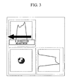
Fig. 3} Fig. 3 is a diagram showing an energy-intensity distribution of a laser beam. - {
Fig. 4} Fig. 4 is a diagram showing an energy-intensity distribution of a laser beam. - {
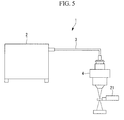
Fig. 5} Fig. 5 is a schematic diagram showing the laser cutting apparatus and a beam-mode measurement unit according to the embodiment of the present invention. - {
Fig. 6} Fig. 6 is a diagram showing an energy-intensity distribution of a laser beam. - {
Fig. 7} Fig. 7 is a photograph showing cut surfaces of a workpiece that has been cut by using the laser cutting apparatus according to the embodiment of the present invention. - {
Fig. 8} Fig. 8 is a plan view showing a workpiece and cutting directions of the workpiece. - {
Fig. 9} Fig. 9 is a diagram showing an energy-intensity distribution of a laser beam, as compared withFig. 8 . - {
Fig. 10} Fig. 10 is a photograph showing cut surfaces of a workpiece that has been cut by using the laser cutting apparatus according to the embodiment of the present invention. - An embodiment according to the present invention will be described below with reference to the drawings.
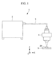
First, alaser cutting apparatus 1 according to the embodiment of the present invention will be described. As shown inFig. 1 , thelaser cutting apparatus 1 is provided with alaser oscillator 2, anoptical fiber 3, acutting head 4, aprocessing stage 5, and so forth. - With the
laser cutting apparatus 1, a laser beam is transmitted to thecutting head 4 from thelaser oscillator 2 via theoptical fiber 3, and the laser beam is focused by lenses in thecutting head 4 to increase the energy density of the laser beam, thereby cutting aworkpiece 20. Here, theworkpiece 20 is a metal, an alloy, or the like. Thelaser cutting apparatus 1 of this embodiment is suitable for cutting a plate-like member having a thickness of about 10 mm to 50 mm. - The
laser oscillator 2 is, for example, a fiber laser oscillator in which an optical fiber itself is used as a medium. In the case of a fiber laser oscillator, a laser beam having a wavelength of 1070 nm to 1080 nm can be obtained. The laser beam generated by thelaser oscillator 2 is transmitted through theoptical fiber 3. Note that the present invention is not limited to a fiber laser, and it can be applied to a CO2 laser, a YAG laser, and so forth. - The
optical fiber 3 is connected to thelaser oscillator 2 at one end and is connected to thecutting head 4 at the other end. Theoptical fiber 3 transmits the laser beam from thelaser oscillator 2 to thecutting head 4. - As shown in
Fig. 2 , thecutting head 4 is provided with a laser entrance portion that includes a movingportion 6 and a supportingportion 8, anoptical system 7, and so forth. The movingportion 6 of the laser entrance portion is connected to an end of theoptical fiber 3, and the laser beam transmitted by theoptical fiber 3 is radiated toward theoptical system 7. Theoptical system 7 is constituted of one or a plurality of lenses, such as focusing lenses or the like, and focuses the laser beam radiated from theoptical fiber 3. By doing so, it is possible to achieve a high energy density enough to cut theworkpiece 20. - As shown in
Fig. 1 , theprocessing stage 5 is moved in a plane as a flat surface (X-Y plane) perpendicular to the beam axis of the laser beam. Theworkpiece 20 is placed on theprocessing stage 5. By doing so, theworkpiece 20 can be moved in the X-Y plane with respect to thecutting head 4. Note that, although a case in which the cuttinghead 4 is fixed will be described in this embodiment, the present invention is not limited to this example. For example, the present invention can also be applied to the case in which theworkpiece 20 is fixed at one location, and theworkpiece 20 is cut by moving the cuttinghead 4. - With the above-described
laser cutting apparatus 1 of this embodiment, thelaser oscillator 2 generates a laser beam, the generated laser beam passes through theoptical fiber 3, and thus, the laser beam is radiated toward the workpiece 20 from the cuttinghead 4. When cutting theworkpiece 20, theprocessing stage 5 on which theworkpiece 20 is placed is moved in the X-Y plane, and thus, theworkpiece 20 is cut in a straight line or in a curved line. - Next, the laser entrance portion provided in the cutting
head 4 of thelaser cutting apparatus 1 according to this embodiment will be described with reference toFig. 2 .
The movingportion 6 is installed on theoptical fiber 3 side of the supportingportion 8 that accommodates theoptical system 7. The movingportion 6 holds theoptical fiber 3. The movingportion 6 can be moved in a plane as a flat surface (X-Y plane) perpendicular to the beam axis of the laser beam. Accordingly, the movingportion 6 is moved in the X-Y plane with respect to theoptical system 7 fixed to the supportingportion 8. As a result, by adjusting the positional relationship between theoptical fiber 3 held by the movingportion 6 and theoptical system 7 fixed to the supportingportion 8, it is possible to change the energy-intensity distribution of the laser beam at a position (processing point) at which theworkpiece 20 is cut. - Specifically, the position of the moving
portion 6 in the X-Y plane is changed so that the energy-intensity distribution of the laser beams becomes substantially uniform in the X-Y plane at the processing point. As shown inFigs. 3 and4 , for example, in the case in which regions having high energy intensities and regions having low energy intensities exist, a uniform energy-intensity distribution can be achieved by moving the movingportion 6 toward the regions having low energy intensities. Note that, depending on the types of lenses in theoptical system 7 and the arrangement thereof, it is also possible to achieve a uniform energy-intensity distribution by, in contrast, moving the movingportion 6 toward the regions having high energy intensities. - As shown in
Fig. 2 , the supportingportion 8 holds theoptical system 7 inside a cylindrically shaped portion. The top surface of the supportingportion 8 and the bottom surface of the movingportion 6 are provided so as to be parallel to each other in the X-Y plane.
The movingportion 6 and the supportingportion 8 are fixed to each other by, for example, tightening fixing screws (not shown), after the relative positions thereof are adjusted, in other words, after their relative positions have been changed. Note that the fixing screw is an example of a fixing part that fixes theoptical fiber 3 with respect to theoptical system 7 after moving and adjusting theoptical fiber 3. Accordingly, the laser beam is radiated from theoptical fiber 3 toward the processing point in a state in which the relative positions of the movingportion 6 and the supportingportion 8 are fixed. - The position of the moving
portion 6 with respect to the supportingportion 8 is changed while measuring the energy-intensity distribution of the laser beam at the processing point. Note that the movingportion 6 or the supportingportion 8 is provided with a moving/adjusting portion (not shown) that includes a mechanism for moving the movingportion 6 relative to the supportingportion 8 in the X-Y plane. - Next, the energy-intensity distribution of the laser beam at the processing point will be described.
As shown inFig. 5 , the energy-intensity distribution of the laser beam at the processing point is measured by a beam-mode measurement unit (beam profiler) 21. The beam-mode measurement unit 21 is disposed in the optical axis of the laser beam when adjusting the position of the movingportion 6.
The energy-intensity distribution represents the distribution of the laser-beam energy intensity at the processing point or near the processing point. As shown inFig. 6 , it is preferable that the adjustment be performed so that intensity-peak portions become substantially equal across the X-Y plane, in other words, so that the energy-intensity distribution is adjusted to have a ring shape. For example, when the axis of theoptical fiber 3 fixed to the movingportion 6 is disposed so as to be aligned with the axis of theoptical system 7, the intensity distribution becomes uneven, and peak portions may be formed only in a deviated portion, as shown inFigs. 3 and4 . In this case, as shown inFig. 8 , cutting a workpiece in the four directions results in cut surfaces having extremely rough surfaces. This is likely because the oxidation balance is lost at cut portions resulting from cutting with laser beams having weak energy intensities. - Therefore, the moving
portion 6 is moved with respect to the supportingportion 8, thereby changing the positional relationship between theoptical fiber 3 fixed to the movingportion 6 and theoptical system 7 fixed to the supportingportion 8, and thus, the energy-intensity distribution is adjusted so as to be substantially equal across the X-Y plane at the processing point. As shown inFig. 6 , when the intensity-peak portions are substantially equal over the X-Y plane, thus forming a ring shape, a stable energy-intensity distribution is achieved inside the ring-shaped peak portions. When theworkpiece 20 is cut by using the cuttinghead 4 adjusted in this way, fine cut surfaces are obtained by cutting in any direction, as shown inFig. 7 . As shown inFig. 8 , when the cutting direction of theworkpiece 20 is changed (directions (1) to (4) in the figure) while maintaining the cuttinghead 4 in the fixed state without rotating it about its axis, the cut surfaces inFig. 7 are obtained as a result. This is likely because surfaces of the laser beams that come in contact with theworkpiece 20 all have high energy intensities, making an oxidation imbalance less likely to occur. - It suffices to adjust the positional relationship between the moving
portion 6 and the supportingportion 8 once during manufacturing, that is, before shipping.Figs. 3 and4 indicate that the energy-intensity distribution becomes uneven when thelaser oscillator 2, theoptical fiber 3, or the cuttinghead 4 is replaced. Therefore, the bias in the energy-intensity distribution is likely due to individual variability among the laser beams emitted from thelaser oscillators 2, the connection portions of theoptical fibers 3, or manufacturing and assembling errors of the cutting heads 4. Specifically, the energy-intensity distribution does not normally change unless thelaser oscillator 2 is replaced or the connections of theoptical fiber 3 are changed; therefore, it suffices to adjust the positional relationship between the movingportion 6 and the supportingportion 8 once during manufacturing, that is, before shipping.
Note that, with thelaser cutting apparatus 1 in which thelaser oscillator 2 is replaced, the positional relationship between the movingportion 6 and the supportingportion 8 may be adjusted by using the movingportion 6 and the beam-mode measurement unit 21 every time the processing setting is changed. - In addition, although the above-described embodiment has been described in terms of a case in which the energy-intensity distribution of the laser beam is changed by adjusting the relative positional relationship between the moving
portion 6 and the supportingportion 8 in the X-Y plane, the present invention is not limited to this example. For example, the energy-intensity distribution of the laser beam may be changed by tilting the optical axis direction of the laser beam radiated from theoptical fiber 3 with respect to the axis of theoptical system 7. In this case, the movingportion 6 or the supportingportion 8 is provided with a moving/adjusting portion having a mechanism for tilting the movingportion 6 with respect to the supportingportion 8, instead of the mechanism for moving the movingportion 6 relative to the supportingportion 8 in the X-Y plane. -
- 1
- laser cutting apparatus
- 2
- laser oscillator
- 3
- optical fiber
- 4
- cutting head
- 5
- processing stage
- 6
- moving portion
- 7
- optical system (lens)
- 8
- supporting portion
- 20
- workpiece
- 21
- beam-mode measurement unit (intensity-distribution measuring portion)
Claims (3)
- A laser cutting apparatus for cutting a workpiece by radiating a laser beam thereon, the laser cutting apparatus comprising:a laser entrance portion to which an optical fiber that transmits the laser beam is fixed; anda lens through which the laser beam radiated from the optical fiber fixed by the laser entrance portion passes,wherein the laser entrance portion includes a moving portion for moving or tilting the optical fiber with respect to the lens, and a fixing portion that fixes the moved or tilted optical fiber with respect to the lens.
- A laser cutting apparatus according to Claim 1, further comprising:an intensity-distribution measuring portion that measures an energy-intensity distribution of the laser beam radiated from the lens,wherein the moving portion is configured to move or tilt the optical fiber based on the measured energy-intensity distribution.
- A laser cutting method for cutting a workpiece by radiating a laser beam thereon, by using a laser cutting apparatus including a laser entrance portion to which an optical fiber that transmits the laser beam is fixed and a lens through which the laser beam radiated from the optical fiber fixed by the laser entrance portion passes, the laser cutting method comprising:moving or tilting the optical fiber fixed by the laser entrance portion with respect to the lens; andfixing the moved or tilted optical fiber with respect to the lens.
Applications Claiming Priority (1)
| Application Number | Priority Date | Filing Date | Title |
|---|---|---|---|
| JP2012250231A JP5943812B2 (en) | 2012-11-14 | 2012-11-14 | Laser cutting apparatus and laser cutting method |
Publications (2)
| Publication Number | Publication Date |
|---|---|
| EP2732905A1 true EP2732905A1 (en) | 2014-05-21 |
| EP2732905B1 EP2732905B1 (en) | 2017-12-06 |
Family
ID=49326561
Family Applications (1)
| Application Number | Title | Priority Date | Filing Date |
|---|---|---|---|
| EP13187865.4A Active EP2732905B1 (en) | 2012-11-14 | 2013-10-09 | Laser cutting apparatus and method using an adjustable optical fibre |
Country Status (3)
| Country | Link |
|---|---|
| US (1) | US10207368B2 (en) |
| EP (1) | EP2732905B1 (en) |
| JP (1) | JP5943812B2 (en) |
Families Citing this family (2)
| Publication number | Priority date | Publication date | Assignee | Title |
|---|---|---|---|---|
| US11597033B2 (en) | 2018-03-23 | 2023-03-07 | Primetals Technologies Japan, Ltd. | Laser processing head, laser processing device, and method for adjusting laser processing head |
| JP7825457B2 (en) * | 2022-03-01 | 2026-03-06 | 株式会社タムロン | Laser beam irradiation optical unit and laser processing device |
Citations (6)
| Publication number | Priority date | Publication date | Assignee | Title |
|---|---|---|---|---|
| US5095517A (en) * | 1990-02-20 | 1992-03-10 | Pirelli Cavi S.P.A. | Swivelling optical connector for joining optical fiber to components and sensor including such connector |
| US5660748A (en) * | 1995-02-28 | 1997-08-26 | Mitsubishi Denki Kabushiki Kaisha | Laser beam machine with an optical fiber cable |
| JP2001116957A (en) * | 1999-10-21 | 2001-04-27 | Minolta Co Ltd | Optical module and light source unit |
| JP2001138084A (en) * | 1999-11-10 | 2001-05-22 | Mitsubishi Electric Corp | Optical fiber mounting position adjusting device and adjusting method |
| JP2003154477A (en) | 2001-11-15 | 2003-05-27 | Nippon Steel Corp | Laser cutting method and apparatus |
| FR2973726A1 (en) * | 2011-04-06 | 2012-10-12 | Air Liquide Welding France | Laser machine, useful for cutting metallic material in the form of e.g. plate by implementation of laser beam, comprises laser source, laser head, laser fiber including upstream end and downstream end, and angular adjustment system |
Family Cites Families (10)
| Publication number | Priority date | Publication date | Assignee | Title |
|---|---|---|---|---|
| DE2922937C2 (en) * | 1979-06-01 | 1981-07-02 | Fabeg Gmbh, 7518 Bretten | Cable coupling for the automatic coupling of electrical heating and / or control current lines as well as light guides for the optical transmission of commands, in particular for rail vehicles |
| JP3531199B2 (en) * | 1994-02-22 | 2004-05-24 | 三菱電機株式会社 | Optical transmission equipment |
| US5937123A (en) * | 1998-04-22 | 1999-08-10 | Eastman Kodak Company | Fiber optical laser collimating device |
| JP4293098B2 (en) * | 2004-09-15 | 2009-07-08 | セイコーエプソン株式会社 | Laser processing method, laser processing equipment, electronic equipment |
| JP4698200B2 (en) * | 2004-10-27 | 2011-06-08 | 日立造船株式会社 | Laser processing method and laser processing apparatus |
| JP5156979B2 (en) * | 2005-10-21 | 2013-03-06 | ナルックス株式会社 | How to attach an optical fiber to an optical fiber coupler |
| CN101432851B (en) * | 2006-03-30 | 2011-06-15 | 日立电脑机器株式会社 | Laser irradiation device, laser irradiation method, and manufacturing method of modified target |
| DE102007035715A1 (en) * | 2006-12-27 | 2008-07-03 | Robert Bosch Gmbh | Laser beam processing device for hardening of workpieces, includes device for imaging reflected laser radiation from workpiece onto sensor |
| US7847213B1 (en) * | 2007-09-11 | 2010-12-07 | Ultratech, Inc. | Method and apparatus for modifying an intensity profile of a coherent photonic beam |
| JP2012024794A (en) * | 2010-07-22 | 2012-02-09 | Amada Co Ltd | Working head of fiber laser beam machine |
-
2012
- 2012-11-14 JP JP2012250231A patent/JP5943812B2/en active Active
-
2013
- 2013-10-08 US US14/048,707 patent/US10207368B2/en active Active
- 2013-10-09 EP EP13187865.4A patent/EP2732905B1/en active Active
Patent Citations (6)
| Publication number | Priority date | Publication date | Assignee | Title |
|---|---|---|---|---|
| US5095517A (en) * | 1990-02-20 | 1992-03-10 | Pirelli Cavi S.P.A. | Swivelling optical connector for joining optical fiber to components and sensor including such connector |
| US5660748A (en) * | 1995-02-28 | 1997-08-26 | Mitsubishi Denki Kabushiki Kaisha | Laser beam machine with an optical fiber cable |
| JP2001116957A (en) * | 1999-10-21 | 2001-04-27 | Minolta Co Ltd | Optical module and light source unit |
| JP2001138084A (en) * | 1999-11-10 | 2001-05-22 | Mitsubishi Electric Corp | Optical fiber mounting position adjusting device and adjusting method |
| JP2003154477A (en) | 2001-11-15 | 2003-05-27 | Nippon Steel Corp | Laser cutting method and apparatus |
| FR2973726A1 (en) * | 2011-04-06 | 2012-10-12 | Air Liquide Welding France | Laser machine, useful for cutting metallic material in the form of e.g. plate by implementation of laser beam, comprises laser source, laser head, laser fiber including upstream end and downstream end, and angular adjustment system |
Also Published As
| Publication number | Publication date |
|---|---|
| US20140131328A1 (en) | 2014-05-15 |
| JP5943812B2 (en) | 2016-07-05 |
| EP2732905B1 (en) | 2017-12-06 |
| JP2014097523A (en) | 2014-05-29 |
| US10207368B2 (en) | 2019-02-19 |
Similar Documents
| Publication | Publication Date | Title |
|---|---|---|
| US9415466B2 (en) | Cutting tool and method and apparatus for manufacturing the same | |
| CN114728371B (en) | Laser processing method for workpiece, processing optical tool and laser processing equipment | |
| US9346126B2 (en) | Laser processing head, laser processing apparatus, optical system of laser processing apparatus, laser processing method, and laser focusing method | |
| TWI466748B (en) | Laser processing apparatus | |
| CN100395069C (en) | Optical fiber laser cutting method | |
| JP5670647B2 (en) | Processing object cutting method | |
| KR100955150B1 (en) | Laser processing equipment | |
| CN1644296B (en) | Laser machining apparatus | |
| US8570657B2 (en) | Fast-axis collimator array | |
| KR20110014596A (en) | Laser Scoring System with Curved Orbit and Method | |
| US8450638B2 (en) | Laser scribing method and apparatus | |
| US9470889B2 (en) | Laser scanning device | |
| CN118234592A (en) | Method for laser welding of workpieces by means of rapid switching between welding zones with different materials to be welded | |
| KR20180064599A (en) | Laser processing apparatus | |
| JP2019005802A (en) | Laser processing method, laser processing apparatus, and laser emission unit | |
| US10207368B2 (en) | Laser cutting apparatus and laser cutting method | |
| JP2019020731A (en) | Apparatus for generating line-shaped intensity distribution of laser beam | |
| KR102288791B1 (en) | Laser processing head and laser processing device and adjustment method of laser processing head | |
| KR20210125361A (en) | Laser processing appartus for quartz ware and laser processing method for quartz ware | |
| JP2021030295A (en) | Laser processing equipment and optical adjustment method | |
| KR101057458B1 (en) | Drilling device and drilling method | |
| KR101828242B1 (en) | Linear laser processing apparatus | |
| KR101928264B1 (en) | Laser beam shaping apparatus | |
| KR100819616B1 (en) | Laser processing equipment | |
| JP2016078043A (en) | Laser processing machine |
Legal Events
| Date | Code | Title | Description |
|---|---|---|---|
| PUAI | Public reference made under article 153(3) epc to a published international application that has entered the european phase |
Free format text: ORIGINAL CODE: 0009012 |
|
| 17P | Request for examination filed |
Effective date: 20131009 |
|
| AK | Designated contracting states |
Kind code of ref document: A1 Designated state(s): AL AT BE BG CH CY CZ DE DK EE ES FI FR GB GR HR HU IE IS IT LI LT LU LV MC MK MT NL NO PL PT RO RS SE SI SK SM TR |
|
| AX | Request for extension of the european patent |
Extension state: BA ME |
|
| R17P | Request for examination filed (corrected) |
Effective date: 20141024 |
|
| RBV | Designated contracting states (corrected) |
Designated state(s): AL AT BE BG CH CY CZ DE DK EE ES FI FR GB GR HR HU IE IS IT LI LT LU LV MC MK MT NL NO PL PT RO RS SE SI SK SM TR |
|
| 17Q | First examination report despatched |
Effective date: 20150331 |
|
| GRAP | Despatch of communication of intention to grant a patent |
Free format text: ORIGINAL CODE: EPIDOSNIGR1 |
|
| INTG | Intention to grant announced |
Effective date: 20170418 |
|
| GRAS | Grant fee paid |
Free format text: ORIGINAL CODE: EPIDOSNIGR3 |
|
| GRAJ | Information related to disapproval of communication of intention to grant by the applicant or resumption of examination proceedings by the epo deleted |
Free format text: ORIGINAL CODE: EPIDOSDIGR1 |
|
| GRAL | Information related to payment of fee for publishing/printing deleted |
Free format text: ORIGINAL CODE: EPIDOSDIGR3 |
|
| GRAR | Information related to intention to grant a patent recorded |
Free format text: ORIGINAL CODE: EPIDOSNIGR71 |
|
| INTC | Intention to grant announced (deleted) | ||
| INTG | Intention to grant announced |
Effective date: 20170831 |
|
| GRAA | (expected) grant |
Free format text: ORIGINAL CODE: 0009210 |
|
| AK | Designated contracting states |
Kind code of ref document: B1 Designated state(s): AL AT BE BG CH CY CZ DE DK EE ES FI FR GB GR HR HU IE IS IT LI LT LU LV MC MK MT NL NO PL PT RO RS SE SI SK SM TR |
|
| REG | Reference to a national code |
Ref country code: GB Ref legal event code: FG4D |
|
| REG | Reference to a national code |
Ref country code: AT Ref legal event code: REF Ref document number: 951952 Country of ref document: AT Kind code of ref document: T Effective date: 20171215 Ref country code: CH Ref legal event code: EP |
|
| REG | Reference to a national code |
Ref country code: IE Ref legal event code: FG4D |
|
| REG | Reference to a national code |
Ref country code: DE Ref legal event code: R096 Ref document number: 602013030328 Country of ref document: DE |
|
| REG | Reference to a national code |
Ref country code: NL Ref legal event code: MP Effective date: 20171206 |
|
| REG | Reference to a national code |
Ref country code: LT Ref legal event code: MG4D |
|
| PG25 | Lapsed in a contracting state [announced via postgrant information from national office to epo] |
Ref country code: NO Free format text: LAPSE BECAUSE OF FAILURE TO SUBMIT A TRANSLATION OF THE DESCRIPTION OR TO PAY THE FEE WITHIN THE PRESCRIBED TIME-LIMIT Effective date: 20180306 Ref country code: SE Free format text: LAPSE BECAUSE OF FAILURE TO SUBMIT A TRANSLATION OF THE DESCRIPTION OR TO PAY THE FEE WITHIN THE PRESCRIBED TIME-LIMIT Effective date: 20171206 Ref country code: ES Free format text: LAPSE BECAUSE OF FAILURE TO SUBMIT A TRANSLATION OF THE DESCRIPTION OR TO PAY THE FEE WITHIN THE PRESCRIBED TIME-LIMIT Effective date: 20171206 Ref country code: LT Free format text: LAPSE BECAUSE OF FAILURE TO SUBMIT A TRANSLATION OF THE DESCRIPTION OR TO PAY THE FEE WITHIN THE PRESCRIBED TIME-LIMIT Effective date: 20171206 Ref country code: FI Free format text: LAPSE BECAUSE OF FAILURE TO SUBMIT A TRANSLATION OF THE DESCRIPTION OR TO PAY THE FEE WITHIN THE PRESCRIBED TIME-LIMIT Effective date: 20171206 |
|
| REG | Reference to a national code |
Ref country code: AT Ref legal event code: MK05 Ref document number: 951952 Country of ref document: AT Kind code of ref document: T Effective date: 20171206 |
|
| PG25 | Lapsed in a contracting state [announced via postgrant information from national office to epo] |
Ref country code: HR Free format text: LAPSE BECAUSE OF FAILURE TO SUBMIT A TRANSLATION OF THE DESCRIPTION OR TO PAY THE FEE WITHIN THE PRESCRIBED TIME-LIMIT Effective date: 20171206 Ref country code: RS Free format text: LAPSE BECAUSE OF FAILURE TO SUBMIT A TRANSLATION OF THE DESCRIPTION OR TO PAY THE FEE WITHIN THE PRESCRIBED TIME-LIMIT Effective date: 20171206 Ref country code: GR Free format text: LAPSE BECAUSE OF FAILURE TO SUBMIT A TRANSLATION OF THE DESCRIPTION OR TO PAY THE FEE WITHIN THE PRESCRIBED TIME-LIMIT Effective date: 20180307 Ref country code: LV Free format text: LAPSE BECAUSE OF FAILURE TO SUBMIT A TRANSLATION OF THE DESCRIPTION OR TO PAY THE FEE WITHIN THE PRESCRIBED TIME-LIMIT Effective date: 20171206 Ref country code: BG Free format text: LAPSE BECAUSE OF FAILURE TO SUBMIT A TRANSLATION OF THE DESCRIPTION OR TO PAY THE FEE WITHIN THE PRESCRIBED TIME-LIMIT Effective date: 20180306 |
|
| PG25 | Lapsed in a contracting state [announced via postgrant information from national office to epo] |
Ref country code: NL Free format text: LAPSE BECAUSE OF FAILURE TO SUBMIT A TRANSLATION OF THE DESCRIPTION OR TO PAY THE FEE WITHIN THE PRESCRIBED TIME-LIMIT Effective date: 20171206 |
|
| PG25 | Lapsed in a contracting state [announced via postgrant information from national office to epo] |
Ref country code: CZ Free format text: LAPSE BECAUSE OF FAILURE TO SUBMIT A TRANSLATION OF THE DESCRIPTION OR TO PAY THE FEE WITHIN THE PRESCRIBED TIME-LIMIT Effective date: 20171206 Ref country code: SK Free format text: LAPSE BECAUSE OF FAILURE TO SUBMIT A TRANSLATION OF THE DESCRIPTION OR TO PAY THE FEE WITHIN THE PRESCRIBED TIME-LIMIT Effective date: 20171206 Ref country code: EE Free format text: LAPSE BECAUSE OF FAILURE TO SUBMIT A TRANSLATION OF THE DESCRIPTION OR TO PAY THE FEE WITHIN THE PRESCRIBED TIME-LIMIT Effective date: 20171206 |
|
| PG25 | Lapsed in a contracting state [announced via postgrant information from national office to epo] |
Ref country code: RO Free format text: LAPSE BECAUSE OF FAILURE TO SUBMIT A TRANSLATION OF THE DESCRIPTION OR TO PAY THE FEE WITHIN THE PRESCRIBED TIME-LIMIT Effective date: 20171206 Ref country code: SM Free format text: LAPSE BECAUSE OF FAILURE TO SUBMIT A TRANSLATION OF THE DESCRIPTION OR TO PAY THE FEE WITHIN THE PRESCRIBED TIME-LIMIT Effective date: 20171206 Ref country code: IT Free format text: LAPSE BECAUSE OF FAILURE TO SUBMIT A TRANSLATION OF THE DESCRIPTION OR TO PAY THE FEE WITHIN THE PRESCRIBED TIME-LIMIT Effective date: 20171206 Ref country code: AT Free format text: LAPSE BECAUSE OF FAILURE TO SUBMIT A TRANSLATION OF THE DESCRIPTION OR TO PAY THE FEE WITHIN THE PRESCRIBED TIME-LIMIT Effective date: 20171206 Ref country code: PL Free format text: LAPSE BECAUSE OF FAILURE TO SUBMIT A TRANSLATION OF THE DESCRIPTION OR TO PAY THE FEE WITHIN THE PRESCRIBED TIME-LIMIT Effective date: 20171206 |
|
| REG | Reference to a national code |
Ref country code: DE Ref legal event code: R097 Ref document number: 602013030328 Country of ref document: DE |
|
| PLBE | No opposition filed within time limit |
Free format text: ORIGINAL CODE: 0009261 |
|
| STAA | Information on the status of an ep patent application or granted ep patent |
Free format text: STATUS: NO OPPOSITION FILED WITHIN TIME LIMIT |
|
| 26N | No opposition filed |
Effective date: 20180907 |
|
| PG25 | Lapsed in a contracting state [announced via postgrant information from national office to epo] |
Ref country code: DK Free format text: LAPSE BECAUSE OF FAILURE TO SUBMIT A TRANSLATION OF THE DESCRIPTION OR TO PAY THE FEE WITHIN THE PRESCRIBED TIME-LIMIT Effective date: 20171206 Ref country code: SI Free format text: LAPSE BECAUSE OF FAILURE TO SUBMIT A TRANSLATION OF THE DESCRIPTION OR TO PAY THE FEE WITHIN THE PRESCRIBED TIME-LIMIT Effective date: 20171206 |
|
| REG | Reference to a national code |
Ref country code: CH Ref legal event code: PL |
|
| GBPC | Gb: european patent ceased through non-payment of renewal fee |
Effective date: 20181009 |
|
| REG | Reference to a national code |
Ref country code: BE Ref legal event code: MM Effective date: 20181031 |
|
| PG25 | Lapsed in a contracting state [announced via postgrant information from national office to epo] |
Ref country code: MC Free format text: LAPSE BECAUSE OF FAILURE TO SUBMIT A TRANSLATION OF THE DESCRIPTION OR TO PAY THE FEE WITHIN THE PRESCRIBED TIME-LIMIT Effective date: 20171206 Ref country code: LU Free format text: LAPSE BECAUSE OF NON-PAYMENT OF DUE FEES Effective date: 20181009 |
|
| REG | Reference to a national code |
Ref country code: IE Ref legal event code: MM4A |
|
| PG25 | Lapsed in a contracting state [announced via postgrant information from national office to epo] |
Ref country code: LI Free format text: LAPSE BECAUSE OF NON-PAYMENT OF DUE FEES Effective date: 20181031 Ref country code: BE Free format text: LAPSE BECAUSE OF NON-PAYMENT OF DUE FEES Effective date: 20181031 Ref country code: FR Free format text: LAPSE BECAUSE OF NON-PAYMENT OF DUE FEES Effective date: 20181031 Ref country code: CH Free format text: LAPSE BECAUSE OF NON-PAYMENT OF DUE FEES Effective date: 20181031 |
|
| PG25 | Lapsed in a contracting state [announced via postgrant information from national office to epo] |
Ref country code: IE Free format text: LAPSE BECAUSE OF NON-PAYMENT OF DUE FEES Effective date: 20181009 Ref country code: GB Free format text: LAPSE BECAUSE OF NON-PAYMENT OF DUE FEES Effective date: 20181009 |
|
| PG25 | Lapsed in a contracting state [announced via postgrant information from national office to epo] |
Ref country code: MT Free format text: LAPSE BECAUSE OF NON-PAYMENT OF DUE FEES Effective date: 20181009 |
|
| PG25 | Lapsed in a contracting state [announced via postgrant information from national office to epo] |
Ref country code: TR Free format text: LAPSE BECAUSE OF FAILURE TO SUBMIT A TRANSLATION OF THE DESCRIPTION OR TO PAY THE FEE WITHIN THE PRESCRIBED TIME-LIMIT Effective date: 20171206 |
|
| PG25 | Lapsed in a contracting state [announced via postgrant information from national office to epo] |
Ref country code: PT Free format text: LAPSE BECAUSE OF FAILURE TO SUBMIT A TRANSLATION OF THE DESCRIPTION OR TO PAY THE FEE WITHIN THE PRESCRIBED TIME-LIMIT Effective date: 20171206 |
|
| PG25 | Lapsed in a contracting state [announced via postgrant information from national office to epo] |
Ref country code: HU Free format text: LAPSE BECAUSE OF FAILURE TO SUBMIT A TRANSLATION OF THE DESCRIPTION OR TO PAY THE FEE WITHIN THE PRESCRIBED TIME-LIMIT; INVALID AB INITIO Effective date: 20131009 Ref country code: MK Free format text: LAPSE BECAUSE OF NON-PAYMENT OF DUE FEES Effective date: 20171206 Ref country code: CY Free format text: LAPSE BECAUSE OF FAILURE TO SUBMIT A TRANSLATION OF THE DESCRIPTION OR TO PAY THE FEE WITHIN THE PRESCRIBED TIME-LIMIT Effective date: 20171206 |
|
| PG25 | Lapsed in a contracting state [announced via postgrant information from national office to epo] |
Ref country code: AL Free format text: LAPSE BECAUSE OF FAILURE TO SUBMIT A TRANSLATION OF THE DESCRIPTION OR TO PAY THE FEE WITHIN THE PRESCRIBED TIME-LIMIT Effective date: 20171206 Ref country code: IS Free format text: LAPSE BECAUSE OF FAILURE TO SUBMIT A TRANSLATION OF THE DESCRIPTION OR TO PAY THE FEE WITHIN THE PRESCRIBED TIME-LIMIT Effective date: 20180406 |
|
| PGFP | Annual fee paid to national office [announced via postgrant information from national office to epo] |
Ref country code: DE Payment date: 20250902 Year of fee payment: 13 |