EP2732799A1 - Systems and methods for deploying an endoluminal sleeve - Google Patents
Systems and methods for deploying an endoluminal sleeve Download PDFInfo
- Publication number
- EP2732799A1 EP2732799A1 EP13193725.2A EP13193725A EP2732799A1 EP 2732799 A1 EP2732799 A1 EP 2732799A1 EP 13193725 A EP13193725 A EP 13193725A EP 2732799 A1 EP2732799 A1 EP 2732799A1
- Authority
- EP
- European Patent Office
- Prior art keywords
- sleeve
- balloon
- rolled
- endoluminal sleeve
- thread
- Prior art date
- Legal status (The legal status is an assumption and is not a legal conclusion. Google has not performed a legal analysis and makes no representation as to the accuracy of the status listed.)
- Granted
Links
- 238000000034 method Methods 0.000 title claims abstract description 37
- 239000000853 adhesive Substances 0.000 claims abstract description 12
- 230000001070 adhesive effect Effects 0.000 claims abstract description 12
- 230000003232 mucoadhesive effect Effects 0.000 claims description 14
- 238000005096 rolling process Methods 0.000 claims description 11
- 239000000843 powder Substances 0.000 claims description 10
- 230000000968 intestinal effect Effects 0.000 description 134
- 210000002784 stomach Anatomy 0.000 description 17
- 235000013305 food Nutrition 0.000 description 11
- 210000001198 duodenum Anatomy 0.000 description 9
- 210000000813 small intestine Anatomy 0.000 description 9
- 235000015097 nutrients Nutrition 0.000 description 8
- 239000000463 material Substances 0.000 description 6
- 210000001187 pylorus Anatomy 0.000 description 6
- 230000008901 benefit Effects 0.000 description 4
- 210000000936 intestine Anatomy 0.000 description 4
- 238000012986 modification Methods 0.000 description 4
- 230000004048 modification Effects 0.000 description 4
- 238000010521 absorption reaction Methods 0.000 description 3
- 230000029087 digestion Effects 0.000 description 3
- 210000000214 mouth Anatomy 0.000 description 3
- 102000004190 Enzymes Human genes 0.000 description 2
- 108090000790 Enzymes Proteins 0.000 description 2
- 210000003238 esophagus Anatomy 0.000 description 2
- 230000014509 gene expression Effects 0.000 description 2
- 239000007943 implant Substances 0.000 description 2
- 239000012528 membrane Substances 0.000 description 2
- 238000003825 pressing Methods 0.000 description 2
- 230000002040 relaxant effect Effects 0.000 description 2
- 238000011282 treatment Methods 0.000 description 2
- 208000001072 type 2 diabetes mellitus Diseases 0.000 description 2
- 241000167880 Hirundinidae Species 0.000 description 1
- 208000008589 Obesity Diseases 0.000 description 1
- 208000031481 Pathologic Constriction Diseases 0.000 description 1
- 229920002472 Starch Polymers 0.000 description 1
- 230000001419 dependent effect Effects 0.000 description 1
- 210000002249 digestive system Anatomy 0.000 description 1
- 230000003467 diminishing effect Effects 0.000 description 1
- 230000002496 gastric effect Effects 0.000 description 1
- 210000004051 gastric juice Anatomy 0.000 description 1
- 210000002429 large intestine Anatomy 0.000 description 1
- 210000003205 muscle Anatomy 0.000 description 1
- 235000020824 obesity Nutrition 0.000 description 1
- 102000004169 proteins and genes Human genes 0.000 description 1
- 108090000623 proteins and genes Proteins 0.000 description 1
- 210000003296 saliva Anatomy 0.000 description 1
- 235000019698 starch Nutrition 0.000 description 1
- 239000008107 starch Substances 0.000 description 1
- 210000001519 tissue Anatomy 0.000 description 1
- 239000002699 waste material Substances 0.000 description 1
- XLYOFNOQVPJJNP-UHFFFAOYSA-N water Substances O XLYOFNOQVPJJNP-UHFFFAOYSA-N 0.000 description 1
- 230000004580 weight loss Effects 0.000 description 1
Images


Classifications
-
- A—HUMAN NECESSITIES
- A61—MEDICAL OR VETERINARY SCIENCE; HYGIENE
- A61F—FILTERS IMPLANTABLE INTO BLOOD VESSELS; PROSTHESES; DEVICES PROVIDING PATENCY TO, OR PREVENTING COLLAPSING OF, TUBULAR STRUCTURES OF THE BODY, e.g. STENTS; ORTHOPAEDIC, NURSING OR CONTRACEPTIVE DEVICES; FOMENTATION; TREATMENT OR PROTECTION OF EYES OR EARS; BANDAGES, DRESSINGS OR ABSORBENT PADS; FIRST-AID KITS
- A61F2/00—Filters implantable into blood vessels; Prostheses, i.e. artificial substitutes or replacements for parts of the body; Appliances for connecting them with the body; Devices providing patency to, or preventing collapsing of, tubular structures of the body, e.g. stents
- A61F2/95—Instruments specially adapted for placement or removal of stents or stent-grafts
- A61F2/958—Inflatable balloons for placing stents or stent-grafts
-
- A—HUMAN NECESSITIES
- A61—MEDICAL OR VETERINARY SCIENCE; HYGIENE
- A61F—FILTERS IMPLANTABLE INTO BLOOD VESSELS; PROSTHESES; DEVICES PROVIDING PATENCY TO, OR PREVENTING COLLAPSING OF, TUBULAR STRUCTURES OF THE BODY, e.g. STENTS; ORTHOPAEDIC, NURSING OR CONTRACEPTIVE DEVICES; FOMENTATION; TREATMENT OR PROTECTION OF EYES OR EARS; BANDAGES, DRESSINGS OR ABSORBENT PADS; FIRST-AID KITS
- A61F5/00—Orthopaedic methods or devices for non-surgical treatment of bones or joints; Nursing devices; Anti-rape devices
- A61F5/0003—Apparatus for the treatment of obesity; Anti-eating devices
- A61F5/0013—Implantable devices or invasive measures
- A61F5/0076—Implantable devices or invasive measures preventing normal digestion, e.g. Bariatric or gastric sleeves
-
- A—HUMAN NECESSITIES
- A61—MEDICAL OR VETERINARY SCIENCE; HYGIENE
- A61F—FILTERS IMPLANTABLE INTO BLOOD VESSELS; PROSTHESES; DEVICES PROVIDING PATENCY TO, OR PREVENTING COLLAPSING OF, TUBULAR STRUCTURES OF THE BODY, e.g. STENTS; ORTHOPAEDIC, NURSING OR CONTRACEPTIVE DEVICES; FOMENTATION; TREATMENT OR PROTECTION OF EYES OR EARS; BANDAGES, DRESSINGS OR ABSORBENT PADS; FIRST-AID KITS
- A61F2/00—Filters implantable into blood vessels; Prostheses, i.e. artificial substitutes or replacements for parts of the body; Appliances for connecting them with the body; Devices providing patency to, or preventing collapsing of, tubular structures of the body, e.g. stents
- A61F2/02—Prostheses implantable into the body
- A61F2/04—Hollow or tubular parts of organs, e.g. bladders, tracheae, bronchi or bile ducts
Landscapes
- Health & Medical Sciences (AREA)
- Engineering & Computer Science (AREA)
- Biomedical Technology (AREA)
- Animal Behavior & Ethology (AREA)
- Public Health (AREA)
- Veterinary Medicine (AREA)
- General Health & Medical Sciences (AREA)
- Heart & Thoracic Surgery (AREA)
- Vascular Medicine (AREA)
- Life Sciences & Earth Sciences (AREA)
- Cardiology (AREA)
- Oral & Maxillofacial Surgery (AREA)
- Transplantation (AREA)
- Child & Adolescent Psychology (AREA)
- Obesity (AREA)
- Orthopedic Medicine & Surgery (AREA)
- Nursing (AREA)
- Gastroenterology & Hepatology (AREA)
- Pulmonology (AREA)
- Media Introduction/Drainage Providing Device (AREA)
Abstract
Description
- This application claims the benefit of and priority from
U.S. Provisional Patent Application No. 61/728,483 filed on November 20, 2012 - Embodiments of the present invention relate to the field of implants for treating obesity and Type II diabetes. More specifically embodiments of the present invention relate to systems and methods for deploying implants for reducing the ability of the body to absorb nutrients.
- The human body absorbs nutrients through the digestive system. Food is introduced through the mouth where a person's teeth masticate the food into smaller pieces. Saliva in the mouth begins the digestion of starch in the food. A person then swallows the food, transporting the food through the esophagus into the stomach. In the stomach, the food is mixed with gastric juice which begins the digestion of protein in the food. The stomach mixes the food with other enzymes. After a period of time, the pyloric sphincter opens at the bottom of the stomach allowing the food to pass into the duodenum where the food mixes with more enzymes. The food continues into the small intestine, where digestion continues and nutrients are adsorbed into the bloodstream. The large majority of the absorption of nutrients occurs in the small intestine. The remaining material is transported to the large intestine where water is absorbed before waste is eliminated from the body.
- Reducing the ability of the body to absorb nutrients has been shown to be an effective means of weight loss and treatment of Type II diabetes. Past treatments for reducing the ability of the body to adsorb nutrients included gastric bypasses, in which the functional volume of the stomach is reduced, and intestinal and/or stomach sleeves, in which the sleeves inhibit the absorption of nutrients. Current intestinal sleeves are placed proximate the pyloric sphincter, with part of the intestinal sleeve in the distal end of the stomach and part of the intestinal sleeve in the duodenum. Current devices may cause sores in the stomach and intestine from the intestinal sleeve rubbing and cutting into tissue as well as twisting and subsequent stricture of the sleeve.
- According to a first aspect of the present invention there is provided a catheter assembly for deploying an endoluminal sleeve, the catheter assembly comprising: a balloon catheter having a distal portion and a proximal portion; a balloon disposed at the distal portion of the balloon catheter, the balloon expandable from a deflated configuration to an expanded configuration; and an endoluminal sleeve disposed about the distal portion of the balloon catheter, the endoluminal sleeve having a rolled portion, and an unrolled portion that is disposed about the balloon, the expanded configuration of the balloon expanding the unrolled portion of the balloon while leaving the rolled portion unexpanded.
- Preferably, said rolled portion is located proximally of said unrolled portion. Suitably, a part of said endoluminal sleeve is rolled distally along the radially in-facing surface of itself so as to provide said rolled portion. Accordingly, the rolled portion may be unrolled proximally, or specifically, by proximal movement relative to the unrolled portion.
- In addition, or otherwise, the endoluminal sleeve may include an adhesive adhered to the endoluminal sleeve. Suitably, the radially out-facing surface of the endoluminal sleeve may have an adhesive material provided thereupon, preferably a mucoadhesive material; such adhesive material may thus be trapped within said rolled portion.
- Preferably, the assembly may comprise actuating means that enables a user to unroll, at least in part, said rolled portion while the endoluminal sleeve is located within a body lumen. The actuating means may suitably include a control portion provided at the proximal end of the catheter assembly. Optionally, the actuating means may apply tension to the rolled portion and/or may include pulling means, such as a thread, that may be pulled proximally to unroll said rolled portion.
- Suitably, the balloon may be shaped such that inflating the balloon to its expanded configuration expands only a part of the sleeve to contact a wall of the body lumen at a first location; specifically, the balloon may expand only a part of the unrolled portion of the sleeve to contact a wall of the body lumen at a first location; a first expanded portion of the sleeve may thus be adhered to the wall of the body lumen at the first location. In addition, or otherwise, the balloon may be shaped such that said rolled portion of the sleeve is not expanded when said part of the sleeve (or part of the unrolled portion of the sleeve) is expanded.
- In embodiments, the balloon catheter may have a distal tip extending beyond the distal portion of the balloon catheter, the distal tip having at least one port disposed therein, wherein the threads extend from the rolled portion into the ports, and from the ports to the proximal portion of the balloon catheter. Hence, or otherwise, the rolled portion may be located distally of said unrolled portion. Suitably, a part of said endoluminal sleeve is rolled proximally along the radially in-facing surface of itself so as to provide said rolled portion. Accordingly, the rolled portion may be unrolled distally, or specifically, by distal movement relative to the unrolled portion. Suitably, said threads may extend distally from said rolled portion into the ports. Hence, or otherwise, the threads may pull said rolled portion distally, so as to unroll it.
- According to a second aspect of the present invention there is provided a method for preparing an catheter assembly for delivery of an endoluminal sleeve, the method comprising: providing the endoluminal sleeve, the endoluminal sleeve having a tubular shape with an interior surface, an exterior surface opposite the interior surface, an axis, a proximal end, and a distal end; positioning the endoluminal sleeve about a mandrel, wherein the exterior surface faces the mandrel defining a lumen and the interior surface faces away from the mandrel; rolling the proximal end of the endoluminal sleeve about the mandrel towards the distal end of the endoluminal sleeve resulting in a partially rolled endoluminal sleeve having a rolled portion and an unrolled portion; inverting the partially rolled endoluminal sleeve, thus positioning the interior surface of the unrolled portion inside the partially rolled endoluminal sleeve to define a lumen and positioning the rolled portion and the thread inside the lumen; and positioning the partially rolled endoluminal sleeve about a balloon catheter with the unrolled portion positioned over a balloon of the balloon catheter wherein the interior surface of the unrolled portion faces the balloon catheter.
- The rolling step may include rolling the endoluminal sleeve distally over said interior surface. The inverting step may alternatively be described as positioning the interior surface of the unrolled portion so as to be radially in-facing and the exterior surface of the unrolled portion so as to be radially out-facing.
- Suitably, the method comprises laying a thread along the interior surface in an axial direction from the proximal end to a location past the distal end of the endoluminal sleeve, preferably prior to said rolling step. Such a rolling step may result in said thread being trapped in said rolled portion. Optionally, laying a thread along said interior surface may comprise placing a center portion of the thread proximate at the proximal end and a first end portion of the thread and a second end portion of the thread to a location past the distal end of the endoluminal sleeve.
- The aforementioned thread may extend generally longitudinally from said first end portion to said centre portion of the thread at the proximal end of the sleeve, whereupon the thread bends back on itself to extend generally longitudinally to said second end portion. Said second end portion may also extend generally longitudinally to the proximal end of the catheter assembly. Said first end portion may extend generally longitudinally to the proximal end of the catheter assembly.
- Embodiments of the invention include a method for delivering an endoluminal sleeve. The method includes introducing a catheter assembly into a body lumen where the catheter assembly comprising a balloon catheter having a distal portion with a balloon and a proximal portion, a sleeve disposed about the distal portion of the balloon catheter, the sleeve having a rolled portion with a thread disposed therein and an unrolled portion disposed about the balloon, the thread extending from the rolled portion to the distal portion of the balloon catheter. The catheter is then positioned proximate a first location within the body lumen. The balloon is inflated expanding the unrolled portion of the sleeve to contact a wall of the body lumen at the first location. A first expanded portion of the sleeve is adhered to the wall of the body lumen at the first location. The thread is tensioned while the first expanded portion of the sleeve is adhered to the wall of the body lumen at the first location causing the sleeve to unroll at least partially. The tension is then relaxed in the thread. The balloon is deflated subsequent to adhering the first expanded portion of the sleeve to the wall of the body lumen at the first location. The catheter is moved to a second location within the body lumen. The balloon is inflated expanding a second portion of the sleeve to contact the wall of the body lumen at the second location. The second portion of the sleeve is adhered to the wall of the body lumen at the second location.
- Embodiments further include a method for preparing a catheter assembly for delivery of an endoluminal sleeve. An endoluminal sleeve having a tubular shape with an interior surface, an exterior surface opposite the interior surface, an axis, a proximal end, and a distal end is provided. The endoluminal sleeve is positioned about a mandrel, wherein the exterior surface faces the mandrel defining a lumen and the interior surface faces away from the mandrel. A thread is laid along the interior surface in an axial direction from the proximal end to a location past the distal end of the endoluminal sleeve. The proximal end of the endoluminal sleeve is rolled about the mandrel towards the distal end of the endoluminal sleeve resulting in a partially rolled endoluminal sleeve having a rolled portion disposed and an unrolled portion. The partially rolled endoluminal sleeve is inverted positioning the interior surface of unrolled portion inside the partially rolled endoluminal sleeve to define a lumen and positioning the rolled portion and the thread inside the lumen. The partially rolled endoluminal sleeve is positioned about a balloon catheter with the unrolled portion positioned over a balloon of the balloon catheter wherein the interior surface of the unrolled portion faces the balloon catheter.
- Embodiments further include a catheter assembly for deploying an endoluminal sleeve. The catheter assembly includes a balloon catheter having a distal portion and a proximal portion, a balloon disposed at the distal portion of the balloon catheter, and an endoluminal sleeve disposed about the distal portion of the balloon catheter. The endoluminal sleeve has a rolled portion rolled inward towards an axis of the balloon catheter with a thread disposed in the rolled portion and an unrolled portion disposed about the balloon, the thread extending from within the rolled portion to the distal portion of the balloon catheter.
- To further clarify the above and other advantages and features of the one or more present inventions, reference to specific embodiments thereof are illustrated in the appended drawings. The drawings depict only typical embodiments and are therefore not to be considered limiting. One or more embodiments will be described and explained with additional specificity and detail through the use of the accompanying drawings in which:
-
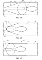
FIG. 1 is a schematic of a stomach and upper lower intestine including the duodenum. -
FIG. 2 is a schematic of a stomach and upper lower intestine including the duodenum illustrating an intestinal sleeve deployed in the duodenum. -
FIG. 3 is a schematic of an intestinal sleeve disposed about a mandrel. -
FIG. 3a is a cross sectional schematic of the intestinal sleeve ofFIG. 3 . -
FIG. 4 is a schematic of the intestinal sleeve ofFIG. 3 with the proximal end being partially rolled. -
FIG. 4a is a schematic of the intestinal sleeve ofFIG. 3 with the distal end being folded. -
FIG. 4b is a schematic of the intestinal sleeve ofFIG. 3 with the distal end being partially pulled over the proximal end. -
FIG. 4c is a schematic of the intestinal sleeve ofFIG. 3 with the proximal end being pulled past the proximal end. -
FIG. 5a is a schematic of the intestinal sleeve ofFIG. 3 with the proximal end being rolled past the distal end. -
FIG. 5b is a schematic of the intestinal sleeve ofFIG. 3 with the distal end being positioned on the outside of the roll. -
FIG. 5c is a schematic of the intestinal sleeve ofFIG. 3 with the distal end being pulled from the roll. -
FIG. 6 illustrates an embodiment of a delivery system with an intestinal sleeve prepared for delivery. -
FIG. 7 illustrates the embodiment ofFIG. 6 with a sleeve retracted for deployment of the intestinal sleeve. -
FIG. 8 illustrates the embodiment ofFIG. 6 with a balloon expanding the intestinal sleeve. -
FIG. 9 illustrates the embodiment ofFIG. 6 with a thread being tensioned to unroll the intestinal sleeve. -
FIG. 10 illustrates the embodiment ofFIG. 6 with the balloon deflated. -
FIG. 11 illustrates the embodiment ofFIG. 6 with the balloon catheter being repositioned. -
FIG. 12 illustrates the embodiment ofFIG. 6 with the balloon being reflated to expand the intestinal sleeve. -
FIG. 13 illustrates the embodiment ofFIG. 6 with tension applied to the threads to unroll the intestinal sleeve. -
FIG. 14 illustrates the embodiment ofFIG. 6 with the balloon being deflated and the balloon catheter repositioned. -
FIG. 15 illustrates the embodiment ofFIG. 6 with the balloon being reflated to expand the intestinal sleeve. - The drawings are not necessarily to scale.
- As used herein, "at least one," "one or more," and "and/or" are open-ended expressions that are both conjunctive and disjunctive in operation. For example, each of the expressions "at least one of A, B and C," "at least one of A, B, or C," "one or more of A, B, and C," "one or more of A, B, or C" and "A, B, and/or C" means A alone, B alone, C alone, A and B together, A and C together, B and C together, or A, B and C together.
- Various embodiments of the present inventions are set forth in the attached figures and in the Detailed Description as provided herein and as embodied by the claims. The embodiments will be described in relation to an intestinal sleeve, but one of ordinary skill in the art would recognize that the system and methods are applicable more generally to an endoluminal sleeve and the deployment of the endoluminal sleeve in a body lumen. It should be understood, however, that this Detailed Description does not contain all of the aspects and embodiments of the one or more present inventions, is not meant to be limiting or restrictive in any manner, and that the invention(s) as disclosed herein is/are and will be understood by those of ordinary skill in the art to encompass obvious improvements and modifications thereto.
- In the following passages, different aspects of the invention are defined in more detail. Each aspect so defined may be combined with any other aspect or aspects unless clearly indicated to the contrary. In particular, any feature indicated as being preferred or advantageous may be combined with any other feature or features indicated as being preferred or advantageous. Additional advantages of the present invention will become readily apparent from the following discussion, particularly when taken together with the accompanying drawings.
-
FIG. 1 is a cross-sectional schematic of astomach 100 and a portion of asmall intestine 102. A ring like muscle, thepyloric sphincter 106, separates the interior of thestomach 100 and the interior of thesmall intestine 102. In a contracted state, thepyloric sphincter 106 inhibits material from passing between thestomach 100 and thesmall intestine 102. When thepyloric sphincter 106 relaxes, the content of thestomach 100 may be passed into thesmall intestine 102. Just beyond thepyloric sphincter 106 is the first section of thesmall intestine 102, termed theduodenum 108. -
FIG. 2 is a cross-section schematic of thestomach 100 ofFIG. 1 , showing an embodiment of anintestinal sleeve 110 fixed in place. Theintestinal sleeve 110 is comprised of a thin, impermeable elastic or plastic membrane adhered to awall 112 of theduodenum 108. Nutrients passing from thestomach 100 into theduodenum 108 are inhibited from absorption by theintestinal sleeve 110. -
FIG. 3 illustrates anintestinal sleeve 300 and amandrel 302.FIG. 3a illustrates a cross section of theintestinal sleeve 300 disposed about themandrel 302. Theintestinal sleeve 300 has aninterior surface 304 and anexterior surface 306 separated by amembrane 308. Theintestinal sleeve 300 is initially inside out, such that theinterior surface 304 is on the outside of theintestinal sleeve 300. In this inside out configuration, theexterior surface 306 defines an inner diameter of theintestinal sleeve 300. Theintestinal sleeve 300 further has aproximal end 310 and adistal end 312. Themandrel 302 is sized to be inserted into the inner diameter of theintestinal sleeve 300. - In preparing the
intestinal sleeve 300 for use, theintestinal sleeve 300 is positioned over themandrel 302 as shown inFIG. 3 . Athread 314 is laid along theinternal surface 304 of theintestinal sleeve 300. The thread may be a suture, a thin wire, a strip of material, a string, or any elongated flexible member. Thethread 314 has afirst end section 316, amiddle section 318, and asecond end section 320. Thethread 314 is laid out such that thefirst end section 316 and thesecond end section 320 are on opposite sides of themandrel 302. Themiddle section 318 is disposed near theproximal end 310 of theintestinal sleeve 300. Thefirst end section 316 and thesecond end section 318 extend longitudinally along theinterior surface 304 and past thedistal end 312 of theintestinal sleeve 300. - The
mandrel 302,intestinal sleeve 300, andthread 314 may then be placed in a basin of mucoadhesive powder to distribute the mucoadhesive powder about theintestinal sleeve 300. Other techniques of applying the mucoadhesive powder are possible and embodiments of the invention are not limited to the use of a basin of mucoadhesive powder. -
FIG. 4 illustrates theintestinal sleeve 300 ofFIG. 3 being rolled about themandrel 302. Theintestinal sleeve 300 may be rolled about themandrel 302 while submersed in the basin of mucoadhesive powder. Theintestinal sleeve 300 is rolled about themandrel 302 from theproximal end 310 toward thedistal end 312. The mucoadhesive powder is trapped within therolls 322 and theinner surface 306 of theintestinal sleeve 300 is exposed on the outside of theroll 322. The thread 314 (shown as a dashed line for clarity) is trapped within theroll 322 as well, with themiddle portion 320 of thethread 314 being located in the innermost part of theroll 322 near the proximal end of the intestinal sleeve. Theintestinal sleeve 300 is rolled short of the complete length of theintestinal sleeve 300 and may stop at a location near a mid-point of theintestinal sleeve 300. In other embodiments, theintestinal sleeve 300 may be rolled a distance greater or less than the mid-point of theintestinal sleeve 300. The distance theintestinal sleeve 300 is rolled may be dependent upon the relative size of the inner diameter compared to the length of theintestinal sleeve 300. - The partially rolled
intestinal sleeve 300 is then inverted so that theouter surface 306 of theintestinal sleeve 300 is on the outside of theintestinal sleeve 300 and theinner surface 304 is on the inside of theintestinal sleeve 300. Theroll 322 is then on the inside of theintestinal sleeve 300 with thethread 314 disposed on the inside as well.FIG. 4a through FIG. 4c illustrates a procedure for inverting the partially rolledintestinal sleeve 300. - In
FIG. 4a , thedistal end 312 of the partially rolledintestinal sleeve 300 is pulled over theinner surface 304 and toward theroll 322 formed on themandrel 302 as shown byarrows 324. As thedistal end 312 is pulled over theinner surface 304, theouter surface 306 is presented to the outside of theintestinal sleeve 300. Afirst portion 326 of theinner surface 304 of theintestinal sleeve 300 faces asecond portion 328 of theinner surface 304 of theintestinal sleeve 300 and thefirst portion 326 of theouter surface 306 of the intestinal sleeve faces the outside.FIG. 4b illustrates thedistal end 312 of the partially rolledintestinal sleeve 300 being pulled over theroll 322 that was formed on themandrel 302. -
FIG. 4c illustrates thedistal end 312 of theintestinal sleeve 300 having been pulled past theroll 322. Thedistal end 312 of theintestinal sleeve 300 may be pulled until theinner surface 304 of theintestinal sleeve 300 contacts theroll 322. Theintestinal sleeve 300 is now inverted from its previous configuration with theouter surface 306 now facing the outside of theintestinal sleeve 300 and theinner surface 304 facing the inside of the intestinal sleeve. Thethread 314 is now on the inside of theintestinal sleeve 300 and may be pulled out of theproximal end 312 of theintestinal sleeve 300 past theroll 322. Thus, thethread 314 extends from the center of theroll 322 at which theproximal end 312 is located, is rolled around theroll 322, and exits theintestinal sleeve 300. - The
distal end 312 of the partially rolledintestinal sleeve 300 may pulled over theroll 322 to invert theintestinal sleeve 300 while theintestinal sleeve 300 is on themandrel 302, as shown inFIG. 4a through 4c , or in other embodiments, theintestinal sleeve 300 may be removed from themandrel 302 prior to pulling theintestinal sleeve 300 over theroll 322. -
FIGS. 5a through 5c illustrate another method for inverting theintestinal sleeve 300 ofFIG. 4 . In this embodiment theroll 322 is rolledpast thedistal end 312 of theintestinal sleeve 300 as shown inFIG. 5a . Thedistal end 312 of theintestinal sleeve 300 is now on the exterior of theroll 322, and theproximal end 310 of theintestinal sleeve 300 is at the innermost part of theroll 322. As shown inFIG. 5c , thedistal portion end 312 of theintestinal sleeve 300 is then pulled in alongitudinal direction 500, partially unrolling theintestinal sleeve 300. Theintestinal sleeve 300 is now inverted with theexterior surface 306 of theintestinal sleeve 300 on the outside of theintestinal sleeve 300 and the interior surface on the inside of theintestinal sleeve 300. -
FIG. 6 illustrates an embodiment of adelivery system 600 with anintestinal sleeve 602 prepared for delivery. Thedelivery system 600 is comprised of aballoon catheter 604 having aballoon 614, and theintestinal sleeve 602. Theballoon catheter 604 may be housed within asheath 606 and adilator tip 608 may be disposed at adistal end 610 of the balloon catheter.Threads 612 extend from aproximal end 620 of theintestinal sleeve 602 and may extend the entire length of theballoon catheter 604. In other embodiments, thethread 612 may extend less than the entire length of theballoon catheter 604 and may be affixed to a separate actuator. For example, thethread 612 may be affixed to a sleeve (not shown) disposed proximal to theballoon 604. Retraction of the sleeve would tension thethread 612. - The
delivery system 600 is guided to a deployment site such as the duodenum of the small intestine in the configuration ofFIG. 6 . Thedelivery system 600 may enter a body through a patient's oral cavity, be guided down the patient's esophagus, and pass through the stomach to the small intestine. - When the
delivery system 600 is positioned at the deployment site, thesheath 606 is retracted proximally exposing theintestinal sleeve 602 as shown inFIG. 7 . Theballoon 614 is then inflated as shown inFIG. 8 , causing theintestinal sleeve 602 to expand radially until theintestinal sleeve 602 contacts a surface such as theintestinal wall 800. Theballoon 614 presses a portion of theintestinal sleeve 602 against theintestinal wall 800. Mucoadhesive powder applied to theintestinal sleeve 602 adheres the portion of theintestinal sleeve 602 to theintestinal wall 800 resulting in an adheredportion 802. - In
FIG. 9 , thethreads 612 are tensioned, partially unrolling theintestinal sleeve 602 in the proximal direction. When theintestinal sleeve 602 has been unrolled a desired distance, the tension is relaxed such that theintestinal sleeve 602 stops unrolling. The adheredportion 802 of theintestinal sleeve 602 remains in place due to the mucoadhesive adhesion and the pressure of theballoon 614. Theballoon 614 is then deflated as shown inFIG. 10 . The adheredportion 802 remains adhered to theintestinal wall 800. Theballoon catheter 604 is then moved in the proximal direction, positioning theballoon 614 proximal to the adheredportion 802 as shown inFIG. 11 . - In
FIG. 12 theballoon 614 is inflated proximal to the adheredportion 802, pressing theintestinal sleeve 602 into theintestinal wall 800. Another portion of theintestinal sleeve 602 adheres to theintestinal wall 800 resulting in the adheredportion 802 being enlarged. Thethreads 612 are again tensioned, further unrolling theintestinal sleeve 602. In some embodiments, theintestinal sleeve 602 may be unrolled completely, or in other embodiments, the tension may be relaxed once theintestinal sleeve 602 has unrolled a desired amount. InFIG. 13 , theintestinal sleeve 602 has been unrolled completely, such that no roll is present. - In
FIG. 13 , thethreads 612 are illustrated as being attached to theintestinal sleeve 602 after being completely unrolled, but in some embodiments thethreads 612 may detach from theintestinal sleeve 602 once it is completely unrolled. In other embodiments, the mucoadhesive or other adhesive may lightly adhere thethread 612 to theintestinal sleeve 602. In such embodiments, further tension of thethread 612 will remove thethread 612 from theintestinal sleeve 602. -
FIG. 14 illustrates thethread 612 having been removed from theintestinal sleeve 602. Theballoon 614 has been deflated and theballoon catheter 604 has been moved proximally, such that theballoon 614 is proximal to the adheredportion 802. The adheredportion 802 remains adhered to theintestinal wall 800. InFIG. 15 theballoon 614 is shown inflated, pressing theproximal end 620 of theintestinal sleeve 602 into theintestinal wall 800. The adheredportion 802 extends from adistal end 622 of theintestinal sleeve 602 to theproximal end 620 of theintestinal sleeve 602. Theballoon 614 can then be deflated once again and theballoon catheter 604 may be removed from the lower intestine. Theintestinal sleeve 602 remains in place due to the mucoadhesive adhering to theintestinal wall 800. - While in foregoing embodiments, and in particular in the embodiments described with reference to
Figures 6 to 15 , theintestinal sleeve 602 has been described as being unrolled in the proximal direction, it should be noted that embodiments of the invention where theintestinal sleeve 602 is unrolled in the distal direction are also contemplated. In such embodiments, theballoon catheter 604 may provide a number of ports at itsdistal end 610. Specifically, these ports may be located distally of theintestinal sleeve 602 and, in particular, may be located distally of the rolled portion of the intestinal sleeve 602 (and may thus be located distally of the unrolled portion of theintestinal sleeve 602 also). - Threads 612 (similar to those described with respect to previous embodiments) may extend distally from the proximal end of the
balloon catheter 604 and may, for example, be provided within a lumen of theballoon catheter 604. Thethreads 612 may thus extend substantially the entire length of theballoon catheter 604. Thethreads 612 may emerge from the ports provided by theballoon catheter 604 and extend in the proximal direction to the rolled portion. As in previous embodiments, part of thethreads 612 may be trapped within the rolled portion; specifically, a middle portion of one or more of thethreads 612 may be located in the innermost part of theroll 322. - Accordingly, when the user actuates the
delivery system 600 so as to pull the proximal ends of thethreads 612 in the proximal direction, this will cause the portion of the threads extending from the ports to the rolled portion of theintestinal sleeve 602 to be pulled distally. Owing to the attachment of these portions of the threads to the rolled portion of theintestinal sleeve 602, the rolled portion may be pulled in the distal direction, thus unrolling it. - Embodiments of the invention have been described in relation to an intestinal sleeve, but are applicable to other endoluminal sleeves. Furthermore, other medical devices may be used in conjunction with the endoluminal sleeve. For example, deploying the endoluminal sleeve may be a part of a larger operation. It should be understood that various changes and modifications to the presently preferred embodiments described herein will be apparent to those skilled in the art. Such changes and modifications can be made without departing from the spirit and scope of the present invention and without diminishing its intended advantages. It is therefore intended that such changes and modifications be covered by the appended claims.
- The following numbered clauses set out specific embodiments that may be useful in understanding the present invention:
- 1. A catheter assembly for deploying an endoluminal sleeve, the catheter assembly comprising:
- a. a balloon catheter having a distal portion and a proximal portion;
- b. a balloon disposed at the distal portion of the balloon catheter; and
- c. an endoluminal sleeve disposed about the distal portion of the balloon catheter, the endoluminal sleeve having a rolled portion with a thread disposed in the rolled portion and an unrolled portion disposed about the balloon, the thread extending from within the rolled portion to the proximal portion of the balloon catheter.
- 2. The catheter assembly of clause 1 further comprising a sheath disposed about the endoluminal sleeve.
- 3. The catheter assembly of clause 1 further comprising a tensioning mechanism adapted to tension the thread.
- 4. The catheter assembly of clause 1 wherein the endoluminal sleeve includes an adhesive adhered to the endoluminal sleeve.
- 5. The catheter assembly of clause 4 wherein the adhesive is a mucoadhesive powder.
- 6. The catheter assembly of clause 1 wherein the balloon catheter has a distal tip extending beyond the distal portion of the balloon catheter, the distal tip having at least 1 port disposed therein, wherein the threads extend from the rolled portion into the ports, and from the ports to the proximal portion of the balloon catheter.
- 7. A method for delivering an endoluminal sleeve, the method comprising:
- a. introducing a catheter assembly into a body lumen, the catheter assembly comprising a balloon catheter having a distal portion with a balloon and a proximal portion, a sleeve disposed about the distal portion of the balloon catheter, the sleeve having a rolled portion with a thread disposed therein and an unrolled portion disposed about the balloon, the thread extending from the rolled portion to the proximal portion of the balloon catheter;
- b. positioning the catheter assembly proximate a first location within the body lumen;
- c. inflating the balloon and expanding the unrolled portion of the sleeve to contact a wall of the body lumen at the first location;
- d. adhering a first expanded portion of the sleeve to the wall of the body lumen at the first location;
- e. tensioning the thread while the first expanded portion of the sleeve is adhered to the wall of the body lumen at the first location causing the sleeve to unroll at least partially;
- f. relaxing the tension in the thread;
- g. deflating the balloon subsequent to adhering the first expanded portion of the sleeve to the wall of the body lumen at the first location;
- h. moving the catheter to a second location within the body lumen proximate the first expanded portion of the sleeve;
- i. inflating the balloon and expanding a second portion of the sleeve to contact the wall of the body lumen at the second location; and
- j. adhering the second portion of the sleeve to the wall of the body lumen at the second location.
- 8. The method of clause 7 further comprising:
- a. tensioning the thread while the second expanded portion of the sleeve is adhered to the wall of the body lumen at the second location causing the sleeve to unroll at least partially;
- b. relaxing the tension in the thread;
- c. deflating the balloon subsequent adhering the second expanded portion of the sleeve to the wall of the body lumen at the second location;
- d. moving the catheter to a third location within the body lumen proximate to the second expanded portion of the sleeve; and
- e. inflating the balloon and expanding a third portion of the sleeve to contact the wall of the body lumen at the third location; and
- f. adhering the third portion of the sleeve to the wall of the body lumen at the third location.
- 9. The method of clause 7 wherein deflating the balloon subsequent to adhering the first expanded portion of the sleeve to the wall of the body lumen at the first location is performed prior to tensioning the thread while the first expanded portion of the sleeve is adhered to the wall of the body lumen at the first location.
- 10. The method of clause 7 wherein deflating the balloon subsequent to adhering the first expanded portion of the sleeve to the wall of the body lumen at the first location is performed subsequent to tensioning the thread while the first expanded portion of the sleeve is adhered to the wall of the body lumen at the first location.
- 11. The method of clause 7 further comprising removing the thread from the sleeve subsequent to adhering the second portion of the sleeve to the wall of the body lumen at the second location.
- 12. The method of clause 7 further comprising removing the balloon catheter from the body lumen subsequent to adhering the second portion of the sleeve to the wall of the body lumen at the second location.
- 13. A method for preparing an catheter assembly for delivery of an endoluminal sleeve, the method comprising:
- a. providing the endoluminal sleeve, the endoluminal sleeve having a tubular shape with an interior surface, an exterior surface opposite the interior surface, an axis, a proximal end, and a distal end;
- b. positioning the endoluminal sleeve about a mandrel, wherein the exterior surface faces the mandrel defining a lumen and the interior surface faces away from the mandrel;
- c. laying a thread along the interior surface in an axial direction from the proximal end to a location past the distal end of the endoluminal sleeve;
- d. rolling the proximal end of the endoluminal sleeve about the mandrel towards the distal end of the endoluminal sleeve resulting in a partially rolled endoluminal sleeve having a rolled portion disposed and an unrolled portion;
- e. inverting the partially rolled endoluminal sleeve positioning the interior surface of unrolled portion inside the partially rolled endoluminal sleeve to define a lumen and positioning the rolled portion and the thread inside the lumen; and
- f. positioning the partially rolled endoluminal sleeve about a balloon catheter with the unrolled portion positioned over a balloon of the balloon catheter wherein the interior surface of the unrolled portion faces the balloon catheter.
- 14. The method of clause 13 wherein laying a thread along the interior surface comprises placing a center portion of the thread proximate at the proximal end and a first end portion of the thread and a second end portion of the thread to a location past the distal end of the endoluminal sleeve.
- 15. The method of clause 14 wherein the first end portion of the thread and the second end portion of the thread are located on opposing sides of the interior surface.
- 16. The method of clause 13 further comprising submersing the endoluminal sleeve in a basin of adhesive.
- 17. The method of clause 16 wherein the adhesive is a mucoadhesive powder.
- 18. The method of clause 16 wherein the endoluminal sleeve is submersed while about the mandrel.
- 19. The method of clause 13 wherein the partially rolled endoluminal sleeve is inverted by rolling the rolled portion beyond the distal end of the endoluminal sleeve.
Claims (15)
- A catheter assembly for deploying an endoluminal sleeve, the catheter assembly comprising:a balloon catheter having a distal portion and a proximal portion;a balloon disposed at the distal portion of the balloon catheter, the balloon expandable from a deflated configuration to an expanded configuration; andan endoluminal sleeve disposed about the distal portion of the balloon catheter, the endoluminal sleeve having a rolled portion, and an unrolled portion that is disposed about the balloon, the expanded configuration of the balloon expanding the unrolled portion of the balloon while leaving the rolled portion unexpanded.
- The catheter assembly of claim 1 further comprising a thread disposed in the rolled portion of the endoluminal sleeve and extending from within the rolled portion to the proximal portion of the balloon catheter.
- The catheter assembly of claim 2, wherein the balloon catheter has a distal tip extending beyond the distal portion of the balloon catheter, the distal tip having at least one port disposed therein, wherein the threads extend from the rolled portion into the ports, and from the ports to the proximal portion of the balloon catheter.
- The catheter assembly of claim 2 or claim 3, further comprising a tensioning mechanism adapted to tension the thread.
- The catheter assembly of any preceding claim, wherein the endoluminal sleeve includes an adhesive adhered to the endoluminal sleeve.
- The catheter assembly of claim 5, wherein the adhesive is a mucoadhesive powder.
- The catheter assembly of any preceding claim, further comprising a sheath disposed about the endoluminal sleeve.
- A method for preparing an catheter assembly for delivery of an endoluminal sleeve, the method comprising:providing the endoluminal sleeve, the endoluminal sleeve having a tubular shape with an interior surface, an exterior surface opposite the interior surface, an axis, a proximal end, and a distal end;positioning the endoluminal sleeve about a mandrel, wherein the exterior surface faces the mandrel defining a lumen and the interior surface faces away from the mandrel;rolling the proximal end of the endoluminal sleeve about the mandrel towards the distal end of the endoluminal sleeve resulting in a partially rolled endoluminal sleeve having a rolled portion and an unrolled portion;inverting the partially rolled endoluminal sleeve, thus positioning the interior surface of the unrolled portion inside the partially rolled endoluminal sleeve to define a lumen and positioning the rolled portion and the thread inside the lumen; andpositioning the partially rolled endoluminal sleeve about a balloon catheter with the unrolled portion positioned over a balloon of the balloon catheter wherein the interior surface of the unrolled portion faces the balloon catheter.
- The method of claim 8, further comprising the step of laying a thread along the interior surface in an axial direction from the proximal end to a location past the distal end of the endoluminal sleeve, preferably prior to said rolling step.
- The method of claim 8 wherein said rolling step results in said thread being trapped in said rolled portion.
- The method of claim 9 or claim 10, wherein laying a thread along the interior surface comprises placing a center portion of the thread at the proximal end and a first end portion of the thread and a second end portion of the thread at a location past the distal end of the endoluminal sleeve.
- The method of claim 11 wherein the first end portion of the thread and the second end portion of the thread are located on opposing sides of the interior surface.
- The method of claim 11 or claim 12 further comprising submersing the endoluminal sleeve in a basin of adhesive.
- The method of any one of claims 8 to 13, wherein the endoluminal sleeve is submersed while about the mandrel.
- The method of any one of claims 8 to 14, wherein the partially rolled endoluminal sleeve is inverted by rolling the rolled portion beyond the distal end of the endoluminal sleeve.
Applications Claiming Priority (1)
| Application Number | Priority Date | Filing Date | Title |
|---|---|---|---|
| US201261728483P | 2012-11-20 | 2012-11-20 |
Publications (2)
| Publication Number | Publication Date |
|---|---|
| EP2732799A1 true EP2732799A1 (en) | 2014-05-21 |
| EP2732799B1 EP2732799B1 (en) | 2016-03-23 |
Family
ID=49641575
Family Applications (1)
| Application Number | Title | Priority Date | Filing Date |
|---|---|---|---|
| EP13193725.2A Active EP2732799B1 (en) | 2012-11-20 | 2013-11-20 | System for deploying an endoluminal sleeve |
Country Status (3)
| Country | Link |
|---|---|
| US (1) | US9681970B2 (en) |
| EP (1) | EP2732799B1 (en) |
| BR (1) | BR102013029585B1 (en) |
Cited By (1)
| Publication number | Priority date | Publication date | Assignee | Title |
|---|---|---|---|---|
| US20230100738A1 (en) * | 2021-09-30 | 2023-03-30 | Appetec Inc | Intragastric Magnetic Device and Delivery System |
Citations (3)
| Publication number | Priority date | Publication date | Assignee | Title |
|---|---|---|---|---|
| US20080255678A1 (en) * | 2007-04-13 | 2008-10-16 | Cully Edward H | Medical apparatus and method of making the same |
| US20110009801A1 (en) * | 2007-09-12 | 2011-01-13 | Medical And Surgical Review, P.C. | Devices and methods for treatment of obesity |
| US20120116286A1 (en) * | 2006-09-02 | 2012-05-10 | Barosense, Inc. | Intestinal sleeves and associated deployment systems and methods |
Family Cites Families (12)
| Publication number | Priority date | Publication date | Assignee | Title |
|---|---|---|---|---|
| DE4018525C2 (en) * | 1990-06-09 | 1994-05-05 | Kaltenbach Martin | Expandable area catheter |
| US5569183A (en) | 1994-06-01 | 1996-10-29 | Archimedes Surgical, Inc. | Method for performing surgery around a viewing space in the interior of the body |
| US6551350B1 (en) * | 1996-12-23 | 2003-04-22 | Gore Enterprise Holdings, Inc. | Kink resistant bifurcated prosthesis |
| US6544278B1 (en) | 1998-11-06 | 2003-04-08 | Scimed Life Systems, Inc. | Rolling membrane stent delivery system |
| US8342183B2 (en) | 2006-04-19 | 2013-01-01 | Vibrynt, Inc. | Devices and methods for treatment of obesity |
| EP2026850B1 (en) | 2006-05-23 | 2014-07-09 | Providence Health System-Oregon d/b/a Providence St. Vincent Medical Center | Systems and methods for introducing and applying a bandage structure within a body lumen or hollow body organ |
| US20070289596A1 (en) * | 2006-06-14 | 2007-12-20 | Campbell Shannon E | Endotracheal cuff and technique for using the same |
| WO2008154450A1 (en) | 2007-06-08 | 2008-12-18 | Valentx, Inc. | Methods and devices for intragastric support of functional or prosthetic gastrointestinal devices |
| CN102186436B (en) | 2008-08-13 | 2016-02-10 | 拜纳瑞克斯医学有限公司 | For the liner of tubular body and for the equipment that applies liner and method |
| US20110034987A1 (en) * | 2009-08-04 | 2011-02-10 | Kennedy Kenneth C | Roll sleeve mechanism for proximal release stent |
| DK2624785T3 (en) * | 2010-10-05 | 2021-05-10 | Edwards Lifesciences Corp | Heart valve prosthesis |
| US9216076B2 (en) * | 2011-09-09 | 2015-12-22 | Endoluminal Sciences Pty. Ltd. | Means for controlled sealing of endovascular devices |
-
2013
- 2013-11-18 BR BR102013029585-0A patent/BR102013029585B1/en active IP Right Grant
- 2013-11-19 US US14/084,233 patent/US9681970B2/en active Active
- 2013-11-20 EP EP13193725.2A patent/EP2732799B1/en active Active
Patent Citations (3)
| Publication number | Priority date | Publication date | Assignee | Title |
|---|---|---|---|---|
| US20120116286A1 (en) * | 2006-09-02 | 2012-05-10 | Barosense, Inc. | Intestinal sleeves and associated deployment systems and methods |
| US20080255678A1 (en) * | 2007-04-13 | 2008-10-16 | Cully Edward H | Medical apparatus and method of making the same |
| US20110009801A1 (en) * | 2007-09-12 | 2011-01-13 | Medical And Surgical Review, P.C. | Devices and methods for treatment of obesity |
Cited By (1)
| Publication number | Priority date | Publication date | Assignee | Title |
|---|---|---|---|---|
| US20230100738A1 (en) * | 2021-09-30 | 2023-03-30 | Appetec Inc | Intragastric Magnetic Device and Delivery System |
Also Published As
| Publication number | Publication date |
|---|---|
| US9681970B2 (en) | 2017-06-20 |
| EP2732799B1 (en) | 2016-03-23 |
| US20140142719A1 (en) | 2014-05-22 |
| BR102013029585B1 (en) | 2021-02-02 |
| BR102013029585A2 (en) | 2015-07-14 |
Similar Documents
| Publication | Publication Date | Title |
|---|---|---|
| EP2061397B1 (en) | Intestinal sleeves and associated deployment systems | |
| CA2652601C (en) | Methods and apparatus for deploying short length ureteral stents | |
| US20110040232A1 (en) | Duodenal liner device | |
| JP4550591B2 (en) | Positioning tool and method for implanting a medical device | |
| JP4996598B2 (en) | Intragastric device for the treatment of obesity | |
| JP5276117B2 (en) | Intragastric bag feeder | |
| US9456917B2 (en) | Endoscopic transoral duodenal sleeve applier | |
| CA2512203A1 (en) | Bariatric sleeve | |
| JP2015211859A (en) | Systems and methods for bariatric therapy | |
| JPH04506311A (en) | Balloon tampon insertion device and how to position it | |
| JP2008526290A (en) | Gastrointestinal floating anchor | |
| WO2008132745A2 (en) | Non-endoscopic insertion and removal of a device | |
| US9681970B2 (en) | Systems and methods for depolying an endoluminal sleeve field | |
| EP3003216A1 (en) | Pancreaticobiliary diversion device | |
| US9414946B2 (en) | Tissue ingrowth intestinal bypass sleeve and method of deployment | |
| JP2018523549A (en) | Endoscopic device comprising a rounding element at the distal end and an expandable duodenal anchor and method of use thereof | |
| JP4320374B2 (en) | Support tube to reinforce the hardness of the medical catheter and guide the medical catheter to the small intestine |
Legal Events
| Date | Code | Title | Description |
|---|---|---|---|
| PUAI | Public reference made under article 153(3) epc to a published international application that has entered the european phase |
Free format text: ORIGINAL CODE: 0009012 |
|
| 17P | Request for examination filed |
Effective date: 20131120 |
|
| AK | Designated contracting states |
Kind code of ref document: A1 Designated state(s): AL AT BE BG CH CY CZ DE DK EE ES FI FR GB GR HR HU IE IS IT LI LT LU LV MC MK MT NL NO PL PT RO RS SE SI SK SM TR |
|
| AX | Request for extension of the european patent |
Extension state: BA ME |
|
| R17P | Request for examination filed (corrected) |
Effective date: 20141120 |
|
| RBV | Designated contracting states (corrected) |
Designated state(s): AL AT BE BG CH CY CZ DE DK EE ES FI FR GB GR HR HU IE IS IT LI LT LU LV MC MK MT NL NO PL PT RO RS SE SI SK SM TR |
|
| GRAP | Despatch of communication of intention to grant a patent |
Free format text: ORIGINAL CODE: EPIDOSNIGR1 |
|
| INTG | Intention to grant announced |
Effective date: 20150918 |
|
| GRAS | Grant fee paid |
Free format text: ORIGINAL CODE: EPIDOSNIGR3 |
|
| GRAA | (expected) grant |
Free format text: ORIGINAL CODE: 0009210 |
|
| AK | Designated contracting states |
Kind code of ref document: B1 Designated state(s): AL AT BE BG CH CY CZ DE DK EE ES FI FR GB GR HR HU IE IS IT LI LT LU LV MC MK MT NL NO PL PT RO RS SE SI SK SM TR |
|
| REG | Reference to a national code |
Ref country code: GB Ref legal event code: FG4D |
|
| REG | Reference to a national code |
Ref country code: CH Ref legal event code: EP |
|
| REG | Reference to a national code |
Ref country code: AT Ref legal event code: REF Ref document number: 782373 Country of ref document: AT Kind code of ref document: T Effective date: 20160415 |
|
| REG | Reference to a national code |
Ref country code: IE Ref legal event code: FG4D |
|
| REG | Reference to a national code |
Ref country code: DE Ref legal event code: R096 Ref document number: 602013005686 Country of ref document: DE |
|
| REG | Reference to a national code |
Ref country code: LT Ref legal event code: MG4D |
|
| REG | Reference to a national code |
Ref country code: NL Ref legal event code: MP Effective date: 20160323 |
|
| PG25 | Lapsed in a contracting state [announced via postgrant information from national office to epo] |
Ref country code: FI Free format text: LAPSE BECAUSE OF FAILURE TO SUBMIT A TRANSLATION OF THE DESCRIPTION OR TO PAY THE FEE WITHIN THE PRESCRIBED TIME-LIMIT Effective date: 20160323 Ref country code: GR Free format text: LAPSE BECAUSE OF FAILURE TO SUBMIT A TRANSLATION OF THE DESCRIPTION OR TO PAY THE FEE WITHIN THE PRESCRIBED TIME-LIMIT Effective date: 20160624 Ref country code: NO Free format text: LAPSE BECAUSE OF FAILURE TO SUBMIT A TRANSLATION OF THE DESCRIPTION OR TO PAY THE FEE WITHIN THE PRESCRIBED TIME-LIMIT Effective date: 20160623 Ref country code: HR Free format text: LAPSE BECAUSE OF FAILURE TO SUBMIT A TRANSLATION OF THE DESCRIPTION OR TO PAY THE FEE WITHIN THE PRESCRIBED TIME-LIMIT Effective date: 20160323 |
|
| REG | Reference to a national code |
Ref country code: AT Ref legal event code: MK05 Ref document number: 782373 Country of ref document: AT Kind code of ref document: T Effective date: 20160323 |
|
| PG25 | Lapsed in a contracting state [announced via postgrant information from national office to epo] |
Ref country code: NL Free format text: LAPSE BECAUSE OF FAILURE TO SUBMIT A TRANSLATION OF THE DESCRIPTION OR TO PAY THE FEE WITHIN THE PRESCRIBED TIME-LIMIT Effective date: 20160323 Ref country code: LT Free format text: LAPSE BECAUSE OF FAILURE TO SUBMIT A TRANSLATION OF THE DESCRIPTION OR TO PAY THE FEE WITHIN THE PRESCRIBED TIME-LIMIT Effective date: 20160323 Ref country code: SE Free format text: LAPSE BECAUSE OF FAILURE TO SUBMIT A TRANSLATION OF THE DESCRIPTION OR TO PAY THE FEE WITHIN THE PRESCRIBED TIME-LIMIT Effective date: 20160323 Ref country code: LV Free format text: LAPSE BECAUSE OF FAILURE TO SUBMIT A TRANSLATION OF THE DESCRIPTION OR TO PAY THE FEE WITHIN THE PRESCRIBED TIME-LIMIT Effective date: 20160323 Ref country code: RS Free format text: LAPSE BECAUSE OF FAILURE TO SUBMIT A TRANSLATION OF THE DESCRIPTION OR TO PAY THE FEE WITHIN THE PRESCRIBED TIME-LIMIT Effective date: 20160323 |
|
| PG25 | Lapsed in a contracting state [announced via postgrant information from national office to epo] |
Ref country code: PL Free format text: LAPSE BECAUSE OF FAILURE TO SUBMIT A TRANSLATION OF THE DESCRIPTION OR TO PAY THE FEE WITHIN THE PRESCRIBED TIME-LIMIT Effective date: 20160323 Ref country code: IS Free format text: LAPSE BECAUSE OF FAILURE TO SUBMIT A TRANSLATION OF THE DESCRIPTION OR TO PAY THE FEE WITHIN THE PRESCRIBED TIME-LIMIT Effective date: 20160723 Ref country code: EE Free format text: LAPSE BECAUSE OF FAILURE TO SUBMIT A TRANSLATION OF THE DESCRIPTION OR TO PAY THE FEE WITHIN THE PRESCRIBED TIME-LIMIT Effective date: 20160323 |
|
| PG25 | Lapsed in a contracting state [announced via postgrant information from national office to epo] |
Ref country code: ES Free format text: LAPSE BECAUSE OF FAILURE TO SUBMIT A TRANSLATION OF THE DESCRIPTION OR TO PAY THE FEE WITHIN THE PRESCRIBED TIME-LIMIT Effective date: 20160323 Ref country code: CZ Free format text: LAPSE BECAUSE OF FAILURE TO SUBMIT A TRANSLATION OF THE DESCRIPTION OR TO PAY THE FEE WITHIN THE PRESCRIBED TIME-LIMIT Effective date: 20160323 Ref country code: AT Free format text: LAPSE BECAUSE OF FAILURE TO SUBMIT A TRANSLATION OF THE DESCRIPTION OR TO PAY THE FEE WITHIN THE PRESCRIBED TIME-LIMIT Effective date: 20160323 Ref country code: RO Free format text: LAPSE BECAUSE OF FAILURE TO SUBMIT A TRANSLATION OF THE DESCRIPTION OR TO PAY THE FEE WITHIN THE PRESCRIBED TIME-LIMIT Effective date: 20160323 Ref country code: PT Free format text: LAPSE BECAUSE OF FAILURE TO SUBMIT A TRANSLATION OF THE DESCRIPTION OR TO PAY THE FEE WITHIN THE PRESCRIBED TIME-LIMIT Effective date: 20160725 Ref country code: SM Free format text: LAPSE BECAUSE OF FAILURE TO SUBMIT A TRANSLATION OF THE DESCRIPTION OR TO PAY THE FEE WITHIN THE PRESCRIBED TIME-LIMIT Effective date: 20160323 Ref country code: SK Free format text: LAPSE BECAUSE OF FAILURE TO SUBMIT A TRANSLATION OF THE DESCRIPTION OR TO PAY THE FEE WITHIN THE PRESCRIBED TIME-LIMIT Effective date: 20160323 |
|
| PG25 | Lapsed in a contracting state [announced via postgrant information from national office to epo] |
Ref country code: BE Free format text: LAPSE BECAUSE OF FAILURE TO SUBMIT A TRANSLATION OF THE DESCRIPTION OR TO PAY THE FEE WITHIN THE PRESCRIBED TIME-LIMIT Effective date: 20160323 Ref country code: IT Free format text: LAPSE BECAUSE OF FAILURE TO SUBMIT A TRANSLATION OF THE DESCRIPTION OR TO PAY THE FEE WITHIN THE PRESCRIBED TIME-LIMIT Effective date: 20160323 |
|
| REG | Reference to a national code |
Ref country code: DE Ref legal event code: R097 Ref document number: 602013005686 Country of ref document: DE |
|
| PLBE | No opposition filed within time limit |
Free format text: ORIGINAL CODE: 0009261 |
|
| STAA | Information on the status of an ep patent application or granted ep patent |
Free format text: STATUS: NO OPPOSITION FILED WITHIN TIME LIMIT |
|
| PG25 | Lapsed in a contracting state [announced via postgrant information from national office to epo] |
Ref country code: DK Free format text: LAPSE BECAUSE OF FAILURE TO SUBMIT A TRANSLATION OF THE DESCRIPTION OR TO PAY THE FEE WITHIN THE PRESCRIBED TIME-LIMIT Effective date: 20160323 |
|
| PG25 | Lapsed in a contracting state [announced via postgrant information from national office to epo] |
Ref country code: BG Free format text: LAPSE BECAUSE OF FAILURE TO SUBMIT A TRANSLATION OF THE DESCRIPTION OR TO PAY THE FEE WITHIN THE PRESCRIBED TIME-LIMIT Effective date: 20160623 |
|
| 26N | No opposition filed |
Effective date: 20170102 |
|
| PG25 | Lapsed in a contracting state [announced via postgrant information from national office to epo] |
Ref country code: SI Free format text: LAPSE BECAUSE OF FAILURE TO SUBMIT A TRANSLATION OF THE DESCRIPTION OR TO PAY THE FEE WITHIN THE PRESCRIBED TIME-LIMIT Effective date: 20160323 |
|
| REG | Reference to a national code |
Ref country code: CH Ref legal event code: PL |
|
| PG25 | Lapsed in a contracting state [announced via postgrant information from national office to epo] |
Ref country code: LI Free format text: LAPSE BECAUSE OF NON-PAYMENT OF DUE FEES Effective date: 20161130 Ref country code: CH Free format text: LAPSE BECAUSE OF NON-PAYMENT OF DUE FEES Effective date: 20161130 |
|
| REG | Reference to a national code |
Ref country code: FR Ref legal event code: ST Effective date: 20170731 |
|
| PG25 | Lapsed in a contracting state [announced via postgrant information from national office to epo] |
Ref country code: LU Free format text: LAPSE BECAUSE OF NON-PAYMENT OF DUE FEES Effective date: 20161130 |
|
| PG25 | Lapsed in a contracting state [announced via postgrant information from national office to epo] |
Ref country code: FR Free format text: LAPSE BECAUSE OF NON-PAYMENT OF DUE FEES Effective date: 20161130 |
|
| PG25 | Lapsed in a contracting state [announced via postgrant information from national office to epo] |
Ref country code: CY Free format text: LAPSE BECAUSE OF FAILURE TO SUBMIT A TRANSLATION OF THE DESCRIPTION OR TO PAY THE FEE WITHIN THE PRESCRIBED TIME-LIMIT Effective date: 20160323 Ref country code: HU Free format text: LAPSE BECAUSE OF FAILURE TO SUBMIT A TRANSLATION OF THE DESCRIPTION OR TO PAY THE FEE WITHIN THE PRESCRIBED TIME-LIMIT; INVALID AB INITIO Effective date: 20131120 |
|
| PG25 | Lapsed in a contracting state [announced via postgrant information from national office to epo] |
Ref country code: MC Free format text: LAPSE BECAUSE OF FAILURE TO SUBMIT A TRANSLATION OF THE DESCRIPTION OR TO PAY THE FEE WITHIN THE PRESCRIBED TIME-LIMIT Effective date: 20160323 Ref country code: MK Free format text: LAPSE BECAUSE OF FAILURE TO SUBMIT A TRANSLATION OF THE DESCRIPTION OR TO PAY THE FEE WITHIN THE PRESCRIBED TIME-LIMIT Effective date: 20160323 |
|
| PG25 | Lapsed in a contracting state [announced via postgrant information from national office to epo] |
Ref country code: MT Free format text: LAPSE BECAUSE OF NON-PAYMENT OF DUE FEES Effective date: 20161120 |
|
| PG25 | Lapsed in a contracting state [announced via postgrant information from national office to epo] |
Ref country code: AL Free format text: LAPSE BECAUSE OF FAILURE TO SUBMIT A TRANSLATION OF THE DESCRIPTION OR TO PAY THE FEE WITHIN THE PRESCRIBED TIME-LIMIT Effective date: 20160323 Ref country code: TR Free format text: LAPSE BECAUSE OF FAILURE TO SUBMIT A TRANSLATION OF THE DESCRIPTION OR TO PAY THE FEE WITHIN THE PRESCRIBED TIME-LIMIT Effective date: 20160323 |
|
| P01 | Opt-out of the competence of the unified patent court (upc) registered |
Effective date: 20230602 |
|
| PGFP | Annual fee paid to national office [announced via postgrant information from national office to epo] |
Ref country code: GB Payment date: 20231013 Year of fee payment: 11 |
|
| PGFP | Annual fee paid to national office [announced via postgrant information from national office to epo] |
Ref country code: IE Payment date: 20231026 Year of fee payment: 11 Ref country code: DE Payment date: 20231010 Year of fee payment: 11 |