EP2732325B1 - Bonding of two elements using a patterned interface - Google Patents
Bonding of two elements using a patterned interface Download PDFInfo
- Publication number
- EP2732325B1 EP2732325B1 EP12745419.7A EP12745419A EP2732325B1 EP 2732325 B1 EP2732325 B1 EP 2732325B1 EP 12745419 A EP12745419 A EP 12745419A EP 2732325 B1 EP2732325 B1 EP 2732325B1
- Authority
- EP
- European Patent Office
- Prior art keywords
- assembly according
- adhesive
- bonding
- holder
- elements
- Prior art date
- Legal status (The legal status is an assumption and is not a legal conclusion. Google has not performed a legal analysis and makes no representation as to the accuracy of the status listed.)
- Active
Links
Images
Classifications
-
- G—PHYSICS
- G02—OPTICS
- G02B—OPTICAL ELEMENTS, SYSTEMS OR APPARATUS
- G02B27/00—Optical systems or apparatus not provided for by any of the groups G02B1/00 - G02B26/00, G02B30/00
- G02B27/28—Optical systems or apparatus not provided for by any of the groups G02B1/00 - G02B26/00, G02B30/00 for polarising
- G02B27/283—Optical systems or apparatus not provided for by any of the groups G02B1/00 - G02B26/00, G02B30/00 for polarising used for beam splitting or combining
-
- G—PHYSICS
- G02—OPTICS
- G02B—OPTICAL ELEMENTS, SYSTEMS OR APPARATUS
- G02B7/00—Mountings, adjusting means, or light-tight connections, for optical elements
- G02B7/18—Mountings, adjusting means, or light-tight connections, for optical elements for prisms; for mirrors
- G02B7/1805—Mountings, adjusting means, or light-tight connections, for optical elements for prisms; for mirrors for prisms
-
- G—PHYSICS
- G02—OPTICS
- G02B—OPTICAL ELEMENTS, SYSTEMS OR APPARATUS
- G02B7/00—Mountings, adjusting means, or light-tight connections, for optical elements
- G02B7/18—Mountings, adjusting means, or light-tight connections, for optical elements for prisms; for mirrors
- G02B7/181—Mountings, adjusting means, or light-tight connections, for optical elements for prisms; for mirrors with means for compensating for changes in temperature or for controlling the temperature; thermal stabilisation
-
- Y—GENERAL TAGGING OF NEW TECHNOLOGICAL DEVELOPMENTS; GENERAL TAGGING OF CROSS-SECTIONAL TECHNOLOGIES SPANNING OVER SEVERAL SECTIONS OF THE IPC; TECHNICAL SUBJECTS COVERED BY FORMER USPC CROSS-REFERENCE ART COLLECTIONS [XRACs] AND DIGESTS
- Y10—TECHNICAL SUBJECTS COVERED BY FORMER USPC
- Y10T—TECHNICAL SUBJECTS COVERED BY FORMER US CLASSIFICATION
- Y10T428/00—Stock material or miscellaneous articles
- Y10T428/31504—Composite [nonstructural laminate]
- Y10T428/3154—Of fluorinated addition polymer from unsaturated monomers
- Y10T428/31544—Addition polymer is perhalogenated
Definitions
- Pattern controlled bonding Shape-controlled bonding, Fixation of optics, Stress-free bonding, Constrained bonding.
- This invention relates in general to fixation by means of any type of adhesive of two- or more parts in an assembly consisting of one or more inhomogeneous part internally joined rigid together, e.g. lenses buildup as doublets or higher - or as the detailed example; Polarizing beam splitters.
- fixation of these types of parts it is beneficial, or even needed to constrain the fixation to only one of the sub-parts/elements, in order to prevent either optical degradation or in worst case physical damages due to thermal stress loading during operation.
- the invention is not limited to optical parts/assemblies; however the optical implementation is used as example - and this is the implemented use in a handheld intraoral 3D scanner called TRIOS manufactured by 3Shape A/S.
- Publication US 2009/0153985 discloses a frame prism retaining frame in which a prism is contained and plurality of adhesive pockets arranged around the prism retaining frame.
- Publication US 6 748 132 B1 dicloses another assembly of particular interest.
- the invention relates to an assembly comprising at least one attachment part and a holder part to which the at least one attachment part is attached, wherein the attachment part is attached to the holder part with an adhesive in an interface area and a pattern control element is attached to one of the parts in the interface area, wherein the pattern control element comprises a non-stick surface.
- the principal function of this invention is to limit the active adhesive area used for the fixation between two parts in a controlled way, but without controlling the adhesive area itself. This is obtained by adding a pattern control element to one of the parts in the interface, which have neglectable influence on the part it attach to, but effectively removing any bonding/adhesion between the two original parts in the area of this pattern control element.
- This method differentiates from other known methods in the way that it doesn't try to control the adhesive material, which in case of liquid glue or heat activated films (HAF) has proven very difficult; but instead prevents bonding by adding the pattern control element in the interface in the area(s) where bonding is prohibited.
- HAF heat activated films
- the area of this "no-bond" zone can be controlled by applying a pattern produced in a material that has a low surfaces energy relatively to the adhesive used.
- Various methods exist for applying this pattern ranging from plasma applied coating or chemical coating to simple labels and tape stamped or cut to shape and manually applied to one of the parts.
- pattern control element and “patterned element” is used interchangeable throughout the present specification.
- the attachment part is an inhomogeneous part comprising a first and a second element.
- first and second elements may for example be prisms, for example in cases where the inhomogeneous part is a beam splitter.
- Such prisms are typically attached to each other in an attachment area by e.g. an adhesive.
- an adhesive e.g. an adhesive
- the holder part have a different CTE than the beam splitter stress will occur in the attachment area due to forces acting on the two prisms. This will alter the characteristics of the beam splitter and render the assembly useless and unreliable. Accordingly, an assembly as described herein has shown to be particularly suitable for beam splitters and other prism assemblies.
- the pattern control element may be provided as a non-stick coating.
- the coating may be directly dispersed on the respective part during production.
- the pattern control element is a tape comprising a non-stick coating.
- Such tape may easily be cut and applied during production.
- a piece of tape may be cut with slightly larger dimensions than the part or element which it covers in order to ensure complete coverage.
- the non-stick coating may advantageously be polytetrafluoroethylene (PTFE), such as Teflon.
- PTFE polytetrafluoroethylene
- silicone coating or other non-stick coating known in the art may be used. It should be understood that the non-stick characteristics of the pattern control element may change depending on the adhesive used. Thus, when applying the assembly as described herein the person skilled in the art would consider combinations of adhesive and pattern control elements that provide a non-stick coating that shows very low adhesive affinity to each other.
- the pattern control element preferably covers at least one of the part elements in the interface area. It is thus completely prevented that the element covered adheres to the adhesive and unintentional forces are applied thereto.
- the inhomogeneous part and the holder part preferably abut each other in the interface area.
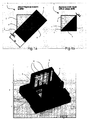
- Figures 1 a and 1 b shows a beam splitter 1 formed of a first prism 2 and a second prism 3, which are cemented together in a refraction surface 4. As discussed then any opposite forces on the two prisms will result in tension in the refraction surface which will alter the characteristics and render the beam splitter useless.
- a tape 5 having a non-stick surface 6 is applied to the sides of the beam splitter which are to be attached to a holder (7 in fig.2 ).
- the sides of the beam splitter and the surfaces of the holder to which the sides abut are referred to as interface areas 8.
- the tape is applied so that it covers the surface of the second prism in the interface areas. Moreover a slight overlap 9 of the tape into the surface of the first prism is provided in order to ensure complete coverage.
- Figure 2 shows the beam splitter 1 placed in the holder 7, thereby providing an assembly as described herein.
- an adhesive 10 such as epoxy.
Landscapes
- Physics & Mathematics (AREA)
- General Physics & Mathematics (AREA)
- Optics & Photonics (AREA)
- Mounting And Adjusting Of Optical Elements (AREA)
- Optical Elements Other Than Lenses (AREA)
Description
- Pattern controlled bonding, Shape-controlled bonding, Fixation of optics, Stress-free bonding, Constrained bonding.
- This invention relates in general to fixation by means of any type of adhesive of two- or more parts in an assembly consisting of one or more inhomogeneous part internally joined rigid together, e.g. lenses buildup as doublets or higher - or as the detailed example; Polarizing beam splitters. For fixation of these types of parts, it is beneficial, or even needed to constrain the fixation to only one of the sub-parts/elements, in order to prevent either optical degradation or in worst case physical damages due to thermal stress loading during operation. The invention is not limited to optical parts/assemblies; however the optical implementation is used as example - and this is the implemented use in a handheld intraoral 3D scanner called TRIOS manufactured by 3Shape A/S.
- This problem is traditionally solved by preventing the bonding material in the area of "no-bond"-wanted; by cutting away unwanted bonding areas or sealing off the zone by a gasket to either keep the glue in or out. These methods are collective more difficult to perform and requires geometric changes to at least one part in the assembly and adds both cost to BOM (bill of materials) and cost due to the handling, whereas our proposed invention only add the cost of the low energy surface (the PTFE-tape in our case) and the extra handling time to add it, which in many cases will be neglectable.
- Publication
US 2009/0153985 discloses a frame prism retaining frame in which a prism is contained and plurality of adhesive pockets arranged around the prism retaining frame. - Publication
US 6 748 132 B1 dicloses another assembly of particular interest. - Accordingly, in one aspect the invention relates to an assembly comprising at least one attachment part and a holder part to which the at least one attachment part is attached, wherein the attachment part is attached to the holder part with an adhesive in an interface area and a pattern control element is attached to one of the parts in the interface area, wherein the pattern control element comprises a non-stick surface.
- The principal function of this invention is to limit the active adhesive area used for the fixation between two parts in a controlled way, but without controlling the adhesive area itself. This is obtained by adding a pattern control element to one of the parts in the interface, which have neglectable influence on the part it attach to, but effectively removing any bonding/adhesion between the two original parts in the area of this pattern control element. This method differentiates from other known methods in the way that it doesn't try to control the adhesive material, which in case of liquid glue or heat activated films (HAF) has proven very difficult; but instead prevents bonding by adding the pattern control element in the interface in the area(s) where bonding is prohibited. The area of this "no-bond" zone can be controlled by applying a pattern produced in a material that has a low surfaces energy relatively to the adhesive used. Various methods exist for applying this pattern, ranging from plasma applied coating or chemical coating to simple labels and tape stamped or cut to shape and manually applied to one of the parts.
- The terms "pattern control element" and "patterned element" is used interchangeable throughout the present specification.
- The application of this is for example advantageous where the two parts have different coefficients of thermal expansion (CTE). By being able to control the adhesive in the interface area it is possible to prevent detachment or unintended deformation by controlling where the parts bond to each other. Thus, by placing a non-adhesive pattern using the pattern control element it is possible to decide with very high precision where the parts are attached in a simple and effective manner.
- The described setup is particular advantageous in embodiments where the attachment part is an inhomogeneous part comprising a first and a second element. Such first and second elements may for example be prisms, for example in cases where the inhomogeneous part is a beam splitter.
- Such prisms are typically attached to each other in an attachment area by e.g. an adhesive. In cases where the holder part have a different CTE than the beam splitter stress will occur in the attachment area due to forces acting on the two prisms. This will alter the characteristics of the beam splitter and render the assembly useless and unreliable. Accordingly, an assembly as described herein has shown to be particularly suitable for beam splitters and other prism assemblies.
- In some embodiment the pattern control element may be provided as a non-stick coating. The coating may be directly dispersed on the respective part during production.
- In an alternative embodiment the pattern control element is a tape comprising a non-stick coating. Such tape may easily be cut and applied during production. Moreover a piece of tape may be cut with slightly larger dimensions than the part or element which it covers in order to ensure complete coverage.
- The non-stick coating may advantageously be polytetrafluoroethylene (PTFE), such as Teflon. However, a silicone coating or other non-stick coating known in the art may be used. It should be understood that the non-stick characteristics of the pattern control element may change depending on the adhesive used. Thus, when applying the assembly as described herein the person skilled in the art would consider combinations of adhesive and pattern control elements that provide a non-stick coating that shows very low adhesive affinity to each other.
- The pattern control element preferably covers at least one of the part elements in the interface area. It is thus completely prevented that the element covered adheres to the adhesive and unintentional forces are applied thereto.
- The inhomogeneous part and the holder part preferably abut each other in the interface area.
- As an example, below is shown the steps in adding a low energy surface in form of a PTFE-tape to an optical beam-splitter, consisting of two prisms, prior to gluing the beam-splitter to an aluminum holder by means of Epoxy glue.
-
-
Figure 1 a and 1 b shows the use of pattern control element in the shape of a masking (in this case, PTFE-tape) which covers the "no-bond" zone, including the transition plus tolerances, and -
Figure 2 shows the PTFE-tape, shown cross-hatched, which prevents the upper half of the prism from being bonded to the aluminum holder by the Epoxy disposed in three milled cavities. -
Figures 1 a and 1 b shows a beam splitter 1 formed of afirst prism 2 and asecond prism 3, which are cemented together in a refraction surface 4. As discussed then any opposite forces on the two prisms will result in tension in the refraction surface which will alter the characteristics and render the beam splitter useless. - Accordingly, in order to solve this problem a
tape 5 having a non-stick surface 6 is applied to the sides of the beam splitter which are to be attached to a holder (7 infig.2 ). The sides of the beam splitter and the surfaces of the holder to which the sides abut are referred to asinterface areas 8. - The tape is applied so that it covers the surface of the second prism in the interface areas. Moreover a
slight overlap 9 of the tape into the surface of the first prism is provided in order to ensure complete coverage. - When the tape has been applied the surplus material is cut away as seen in
fig. 1b . -
Figure 2 shows the beam splitter 1 placed in theholder 7, thereby providing an assembly as described herein. In order to secure the beam splitter in the holder it is adhered to the holder by an adhesive 10, such as epoxy. - During production no advanced techniques or accurate adhesive disposal system needs to be used since the non-stick surface of the
tape 5 will prevent adhesive to stick to the surface of the second prism. Thus, only the first prism is effectively attached to the holder and if the holder expands differently than the beam splitter due to different CTE values, no tension will build up between the two prisms and the characteristics of the beam splitter will remain constant and reliable.
Claims (9)
- An assembly comprising at least one attachment part (2) and a holder part (7) to which the at least one attachment part (2) is attached,
wherein the attachment part (2) is attached to the holder part (7) with an adhesive (10) in an interface area (8) and a patterned elementis (5) attached to one of the parts in the interface area (8), characterised in that the patterned element comprises a non-stick surface (6). - An assembly according to claim 1, wherein the attachment part is an inhomogeneous part comprising at least a first element and a second element.
- An assembly according to claim 2, wherein the first and second elements are prisms.
- An assembly according to claim 2 or 3, wherein the inhomogeneous part is a beam splitter.
- An assembly according to any one of the claims 1 - 4, wherein the patterned element is a non-stick coating.
- An assembly according to any one of the claims 1 - 4, wherein the patterned element is a tape comprising a non-stick coating.
- An assembly according to claim 5 or 6, wherein the non-stick coating is polytetrafluoroethylene.
- An assembly according to claim 2 and any one of the claims 3 - 7, wherein the patterned element covers at least one of the part elements in the interface area.
- An assembly according to claim 2 and any one of the claims 3 - 8, wherein the inhomogeneous part and the holder part abuts each other in the interface area.
Applications Claiming Priority (3)
| Application Number | Priority Date | Filing Date | Title |
|---|---|---|---|
| DKPA201100549 | 2011-07-15 | ||
| DKPA201100551 | 2011-07-18 | ||
| PCT/EP2012/063690 WO2013010911A1 (en) | 2011-07-15 | 2012-07-12 | Bonding of two elements using a patterned interface |
Publications (2)
| Publication Number | Publication Date |
|---|---|
| EP2732325A1 EP2732325A1 (en) | 2014-05-21 |
| EP2732325B1 true EP2732325B1 (en) | 2016-02-10 |
Family
ID=46639984
Family Applications (1)
| Application Number | Title | Priority Date | Filing Date |
|---|---|---|---|
| EP12745419.7A Active EP2732325B1 (en) | 2011-07-15 | 2012-07-12 | Bonding of two elements using a patterned interface |
Country Status (4)
| Country | Link |
|---|---|
| US (1) | US20140218805A1 (en) |
| EP (1) | EP2732325B1 (en) |
| ES (1) | ES2564942T3 (en) |
| WO (1) | WO2013010911A1 (en) |
Families Citing this family (2)
| Publication number | Priority date | Publication date | Assignee | Title |
|---|---|---|---|---|
| WO2022199797A1 (en) * | 2021-03-23 | 2022-09-29 | Trumpf Lasersystems For Semiconductor Manufacturing Gmbh | Method for producing a housing provided for receiving and for defined positioning of at least one optical component, and housing produced by such a method |
| JP2022155031A (en) * | 2021-03-30 | 2022-10-13 | 日本電産株式会社 | Optical unit, smartphone, and manufacturing method of optical unit |
Family Cites Families (3)
| Publication number | Priority date | Publication date | Assignee | Title |
|---|---|---|---|---|
| JP2000347012A (en) * | 1999-03-26 | 2000-12-15 | Nikon Corp | Color separation prism, projection display device and camera including the prism |
| JP4569113B2 (en) * | 2004-01-22 | 2010-10-27 | 富士フイルム株式会社 | projector |
| US8018522B2 (en) * | 2006-02-10 | 2011-09-13 | Panasonic Corporation | Lens barrel, image pickup device, lens barrel inspecting method, and lens barrel manufacturing method |
-
2012
- 2012-07-12 ES ES12745419.7T patent/ES2564942T3/en active Active
- 2012-07-12 EP EP12745419.7A patent/EP2732325B1/en active Active
- 2012-07-12 WO PCT/EP2012/063690 patent/WO2013010911A1/en not_active Ceased
- 2012-07-12 US US14/232,336 patent/US20140218805A1/en not_active Abandoned
Also Published As
| Publication number | Publication date |
|---|---|
| US20140218805A1 (en) | 2014-08-07 |
| WO2013010911A1 (en) | 2013-01-24 |
| ES2564942T3 (en) | 2016-03-30 |
| EP2732325A1 (en) | 2014-05-21 |
Similar Documents
| Publication | Publication Date | Title |
|---|---|---|
| US4469929A (en) | Method for securing optical and electro-optical components | |
| EP1193517A2 (en) | Bonding structures for optical members | |
| US9261661B2 (en) | Structures of connecting optical waveguide parts and holding parts of holding optical input members, and a method of producing the same | |
| JP2015045875A (en) | Welding method and device having welded components | |
| WO2008108178A1 (en) | Microchip manufacturing method | |
| US20140218805A1 (en) | Pattern controlled bonding | |
| JP2023531814A (en) | Hermetically sealed package and manufacturing method thereof | |
| KR101349174B1 (en) | Method of sawing semiconductor wafer, semiconductor chip and chamber for sawing wafer | |
| JP5535262B2 (en) | Optical component bonding method and optical device | |
| JP2010243566A (en) | Adhesion fixing method and method of fixing optical element | |
| US10754117B2 (en) | Joined optical member | |
| JP2000347083A (en) | Optical component bonding structure and method of manufacturing the same | |
| JP5612550B2 (en) | Laser fusion fiber alignment parts | |
| US20080260330A1 (en) | Alignment with thin bonding layer of optical components | |
| JP4156442B2 (en) | Planar optical circuit component and manufacturing method thereof | |
| JP2008134662A (en) | Planar optical circuit component and manufacturing method thereof | |
| WO2022251832A1 (en) | Singulation and edge-sealing of multilayer polymer eyepiece | |
| WO2016009459A1 (en) | Temperature sensor | |
| US20110299183A1 (en) | Bonding technique to minimize distortion on a deformable mirror | |
| JP2003255207A (en) | Optical element and method of bonding optical element | |
| US8711666B2 (en) | Adhesive structure of optical device, adhesion method, and optical pickup device | |
| JP5163041B2 (en) | Optical element fixing device and manufacturing method thereof | |
| JPS6360409A (en) | Protecting method for optical parts | |
| JP5905563B1 (en) | Manufacturing method of semiconductor laser module | |
| CN103311787A (en) | Intracavity frequency doubling microchip laser and preparation method thereof |
Legal Events
| Date | Code | Title | Description |
|---|---|---|---|
| PUAI | Public reference made under article 153(3) epc to a published international application that has entered the european phase |
Free format text: ORIGINAL CODE: 0009012 |
|
| 17P | Request for examination filed |
Effective date: 20140212 |
|
| AK | Designated contracting states |
Kind code of ref document: A1 Designated state(s): AL AT BE BG CH CY CZ DE DK EE ES FI FR GB GR HR HU IE IS IT LI LT LU LV MC MK MT NL NO PL PT RO RS SE SI SK SM TR |
|
| DAX | Request for extension of the european patent (deleted) | ||
| 17Q | First examination report despatched |
Effective date: 20150203 |
|
| GRAP | Despatch of communication of intention to grant a patent |
Free format text: ORIGINAL CODE: EPIDOSNIGR1 |
|
| INTG | Intention to grant announced |
Effective date: 20150803 |
|
| GRAS | Grant fee paid |
Free format text: ORIGINAL CODE: EPIDOSNIGR3 |
|
| GRAA | (expected) grant |
Free format text: ORIGINAL CODE: 0009210 |
|
| AK | Designated contracting states |
Kind code of ref document: B1 Designated state(s): AL AT BE BG CH CY CZ DE DK EE ES FI FR GB GR HR HU IE IS IT LI LT LU LV MC MK MT NL NO PL PT RO RS SE SI SK SM TR |
|
| REG | Reference to a national code |
Ref country code: GB Ref legal event code: FG4D |
|
| REG | Reference to a national code |
Ref country code: AT Ref legal event code: REF Ref document number: 774932 Country of ref document: AT Kind code of ref document: T Effective date: 20160215 Ref country code: CH Ref legal event code: EP |
|
| REG | Reference to a national code |
Ref country code: IE Ref legal event code: FG4D |
|
| REG | Reference to a national code |
Ref country code: DE Ref legal event code: R096 Ref document number: 602012014706 Country of ref document: DE |
|
| REG | Reference to a national code |
Ref country code: ES Ref legal event code: FG2A Ref document number: 2564942 Country of ref document: ES Kind code of ref document: T3 Effective date: 20160330 |
|
| REG | Reference to a national code |
Ref country code: LT Ref legal event code: MG4D |
|
| REG | Reference to a national code |
Ref country code: NL Ref legal event code: MP Effective date: 20160210 |
|
| REG | Reference to a national code |
Ref country code: AT Ref legal event code: MK05 Ref document number: 774932 Country of ref document: AT Kind code of ref document: T Effective date: 20160210 |
|
| REG | Reference to a national code |
Ref country code: FR Ref legal event code: PLFP Year of fee payment: 5 |
|
| PG25 | Lapsed in a contracting state [announced via postgrant information from national office to epo] |
Ref country code: HR Free format text: LAPSE BECAUSE OF FAILURE TO SUBMIT A TRANSLATION OF THE DESCRIPTION OR TO PAY THE FEE WITHIN THE PRESCRIBED TIME-LIMIT Effective date: 20160210 Ref country code: FI Free format text: LAPSE BECAUSE OF FAILURE TO SUBMIT A TRANSLATION OF THE DESCRIPTION OR TO PAY THE FEE WITHIN THE PRESCRIBED TIME-LIMIT Effective date: 20160210 Ref country code: NO Free format text: LAPSE BECAUSE OF FAILURE TO SUBMIT A TRANSLATION OF THE DESCRIPTION OR TO PAY THE FEE WITHIN THE PRESCRIBED TIME-LIMIT Effective date: 20160510 Ref country code: GR Free format text: LAPSE BECAUSE OF FAILURE TO SUBMIT A TRANSLATION OF THE DESCRIPTION OR TO PAY THE FEE WITHIN THE PRESCRIBED TIME-LIMIT Effective date: 20160511 |
|
| PG25 | Lapsed in a contracting state [announced via postgrant information from national office to epo] |
Ref country code: PT Free format text: LAPSE BECAUSE OF FAILURE TO SUBMIT A TRANSLATION OF THE DESCRIPTION OR TO PAY THE FEE WITHIN THE PRESCRIBED TIME-LIMIT Effective date: 20160613 Ref country code: PL Free format text: LAPSE BECAUSE OF FAILURE TO SUBMIT A TRANSLATION OF THE DESCRIPTION OR TO PAY THE FEE WITHIN THE PRESCRIBED TIME-LIMIT Effective date: 20160210 Ref country code: NL Free format text: LAPSE BECAUSE OF FAILURE TO SUBMIT A TRANSLATION OF THE DESCRIPTION OR TO PAY THE FEE WITHIN THE PRESCRIBED TIME-LIMIT Effective date: 20160210 Ref country code: LT Free format text: LAPSE BECAUSE OF FAILURE TO SUBMIT A TRANSLATION OF THE DESCRIPTION OR TO PAY THE FEE WITHIN THE PRESCRIBED TIME-LIMIT Effective date: 20160210 Ref country code: IS Free format text: LAPSE BECAUSE OF FAILURE TO SUBMIT A TRANSLATION OF THE DESCRIPTION OR TO PAY THE FEE WITHIN THE PRESCRIBED TIME-LIMIT Effective date: 20160610 Ref country code: AT Free format text: LAPSE BECAUSE OF FAILURE TO SUBMIT A TRANSLATION OF THE DESCRIPTION OR TO PAY THE FEE WITHIN THE PRESCRIBED TIME-LIMIT Effective date: 20160210 Ref country code: SE Free format text: LAPSE BECAUSE OF FAILURE TO SUBMIT A TRANSLATION OF THE DESCRIPTION OR TO PAY THE FEE WITHIN THE PRESCRIBED TIME-LIMIT Effective date: 20160210 Ref country code: LV Free format text: LAPSE BECAUSE OF FAILURE TO SUBMIT A TRANSLATION OF THE DESCRIPTION OR TO PAY THE FEE WITHIN THE PRESCRIBED TIME-LIMIT Effective date: 20160210 Ref country code: RS Free format text: LAPSE BECAUSE OF FAILURE TO SUBMIT A TRANSLATION OF THE DESCRIPTION OR TO PAY THE FEE WITHIN THE PRESCRIBED TIME-LIMIT Effective date: 20160210 |
|
| PG25 | Lapsed in a contracting state [announced via postgrant information from national office to epo] |
Ref country code: DK Free format text: LAPSE BECAUSE OF FAILURE TO SUBMIT A TRANSLATION OF THE DESCRIPTION OR TO PAY THE FEE WITHIN THE PRESCRIBED TIME-LIMIT Effective date: 20160210 Ref country code: EE Free format text: LAPSE BECAUSE OF FAILURE TO SUBMIT A TRANSLATION OF THE DESCRIPTION OR TO PAY THE FEE WITHIN THE PRESCRIBED TIME-LIMIT Effective date: 20160210 |
|
| REG | Reference to a national code |
Ref country code: DE Ref legal event code: R097 Ref document number: 602012014706 Country of ref document: DE |
|
| PG25 | Lapsed in a contracting state [announced via postgrant information from national office to epo] |
Ref country code: SK Free format text: LAPSE BECAUSE OF FAILURE TO SUBMIT A TRANSLATION OF THE DESCRIPTION OR TO PAY THE FEE WITHIN THE PRESCRIBED TIME-LIMIT Effective date: 20160210 Ref country code: SM Free format text: LAPSE BECAUSE OF FAILURE TO SUBMIT A TRANSLATION OF THE DESCRIPTION OR TO PAY THE FEE WITHIN THE PRESCRIBED TIME-LIMIT Effective date: 20160210 Ref country code: CZ Free format text: LAPSE BECAUSE OF FAILURE TO SUBMIT A TRANSLATION OF THE DESCRIPTION OR TO PAY THE FEE WITHIN THE PRESCRIBED TIME-LIMIT Effective date: 20160210 Ref country code: RO Free format text: LAPSE BECAUSE OF FAILURE TO SUBMIT A TRANSLATION OF THE DESCRIPTION OR TO PAY THE FEE WITHIN THE PRESCRIBED TIME-LIMIT Effective date: 20160210 |
|
| PLBE | No opposition filed within time limit |
Free format text: ORIGINAL CODE: 0009261 |
|
| STAA | Information on the status of an ep patent application or granted ep patent |
Free format text: STATUS: NO OPPOSITION FILED WITHIN TIME LIMIT |
|
| PG25 | Lapsed in a contracting state [announced via postgrant information from national office to epo] |
Ref country code: BE Free format text: LAPSE BECAUSE OF FAILURE TO SUBMIT A TRANSLATION OF THE DESCRIPTION OR TO PAY THE FEE WITHIN THE PRESCRIBED TIME-LIMIT Effective date: 20160210 |
|
| 26N | No opposition filed |
Effective date: 20161111 |
|
| PG25 | Lapsed in a contracting state [announced via postgrant information from national office to epo] |
Ref country code: BG Free format text: LAPSE BECAUSE OF FAILURE TO SUBMIT A TRANSLATION OF THE DESCRIPTION OR TO PAY THE FEE WITHIN THE PRESCRIBED TIME-LIMIT Effective date: 20160510 Ref country code: SI Free format text: LAPSE BECAUSE OF FAILURE TO SUBMIT A TRANSLATION OF THE DESCRIPTION OR TO PAY THE FEE WITHIN THE PRESCRIBED TIME-LIMIT Effective date: 20160210 |
|
| REG | Reference to a national code |
Ref country code: CH Ref legal event code: PL |
|
| GBPC | Gb: european patent ceased through non-payment of renewal fee |
Effective date: 20160712 |
|
| PG25 | Lapsed in a contracting state [announced via postgrant information from national office to epo] |
Ref country code: MC Free format text: LAPSE BECAUSE OF FAILURE TO SUBMIT A TRANSLATION OF THE DESCRIPTION OR TO PAY THE FEE WITHIN THE PRESCRIBED TIME-LIMIT Effective date: 20160210 |
|
| PG25 | Lapsed in a contracting state [announced via postgrant information from national office to epo] |
Ref country code: LI Free format text: LAPSE BECAUSE OF NON-PAYMENT OF DUE FEES Effective date: 20160731 Ref country code: CH Free format text: LAPSE BECAUSE OF NON-PAYMENT OF DUE FEES Effective date: 20160731 |
|
| REG | Reference to a national code |
Ref country code: IE Ref legal event code: MM4A |
|
| PG25 | Lapsed in a contracting state [announced via postgrant information from national office to epo] |
Ref country code: GB Free format text: LAPSE BECAUSE OF NON-PAYMENT OF DUE FEES Effective date: 20160712 |
|
| REG | Reference to a national code |
Ref country code: FR Ref legal event code: PLFP Year of fee payment: 6 |
|
| PG25 | Lapsed in a contracting state [announced via postgrant information from national office to epo] |
Ref country code: IE Free format text: LAPSE BECAUSE OF NON-PAYMENT OF DUE FEES Effective date: 20160712 |
|
| PG25 | Lapsed in a contracting state [announced via postgrant information from national office to epo] |
Ref country code: LU Free format text: LAPSE BECAUSE OF NON-PAYMENT OF DUE FEES Effective date: 20160712 |
|
| PG25 | Lapsed in a contracting state [announced via postgrant information from national office to epo] |
Ref country code: HU Free format text: LAPSE BECAUSE OF FAILURE TO SUBMIT A TRANSLATION OF THE DESCRIPTION OR TO PAY THE FEE WITHIN THE PRESCRIBED TIME-LIMIT; INVALID AB INITIO Effective date: 20120712 Ref country code: CY Free format text: LAPSE BECAUSE OF FAILURE TO SUBMIT A TRANSLATION OF THE DESCRIPTION OR TO PAY THE FEE WITHIN THE PRESCRIBED TIME-LIMIT Effective date: 20160210 |
|
| PG25 | Lapsed in a contracting state [announced via postgrant information from national office to epo] |
Ref country code: MT Free format text: LAPSE BECAUSE OF NON-PAYMENT OF DUE FEES Effective date: 20160731 Ref country code: MK Free format text: LAPSE BECAUSE OF FAILURE TO SUBMIT A TRANSLATION OF THE DESCRIPTION OR TO PAY THE FEE WITHIN THE PRESCRIBED TIME-LIMIT Effective date: 20160210 |
|
| REG | Reference to a national code |
Ref country code: FR Ref legal event code: PLFP Year of fee payment: 7 |
|
| PG25 | Lapsed in a contracting state [announced via postgrant information from national office to epo] |
Ref country code: AL Free format text: LAPSE BECAUSE OF FAILURE TO SUBMIT A TRANSLATION OF THE DESCRIPTION OR TO PAY THE FEE WITHIN THE PRESCRIBED TIME-LIMIT Effective date: 20160210 Ref country code: TR Free format text: LAPSE BECAUSE OF FAILURE TO SUBMIT A TRANSLATION OF THE DESCRIPTION OR TO PAY THE FEE WITHIN THE PRESCRIBED TIME-LIMIT Effective date: 20160210 |
|
| P01 | Opt-out of the competence of the unified patent court (upc) registered |
Effective date: 20230529 |
|
| PGFP | Annual fee paid to national office [announced via postgrant information from national office to epo] |
Ref country code: ES Payment date: 20250826 Year of fee payment: 14 |
|
| PGFP | Annual fee paid to national office [announced via postgrant information from national office to epo] |
Ref country code: DE Payment date: 20250722 Year of fee payment: 14 |
|
| PGFP | Annual fee paid to national office [announced via postgrant information from national office to epo] |
Ref country code: IT Payment date: 20260619 Year of fee payment: 15 |
|
| PGFP | Annual fee paid to national office [announced via postgrant information from national office to epo] |
Ref country code: FR Payment date: 20260519 Year of fee payment: 15 |