EP2732089B1 - Verfahren zum herstellen einer beschickungstür sowie beschickungstür für eine wäschebehandlungsmaschine - Google Patents
Verfahren zum herstellen einer beschickungstür sowie beschickungstür für eine wäschebehandlungsmaschine Download PDFInfo
- Publication number
- EP2732089B1 EP2732089B1 EP12729164.9A EP12729164A EP2732089B1 EP 2732089 B1 EP2732089 B1 EP 2732089B1 EP 12729164 A EP12729164 A EP 12729164A EP 2732089 B1 EP2732089 B1 EP 2732089B1
- Authority
- EP
- European Patent Office
- Prior art keywords
- door
- frame
- support regions
- loading door
- viewing pane
- Prior art date
- Legal status (The legal status is an assumption and is not a legal conclusion. Google has not performed a legal analysis and makes no representation as to the accuracy of the status listed.)
- Active
Links
Images


Classifications
-
- D—TEXTILES; PAPER
- D06—TREATMENT OF TEXTILES OR THE LIKE; LAUNDERING; FLEXIBLE MATERIALS NOT OTHERWISE PROVIDED FOR
- D06F—LAUNDERING, DRYING, IRONING, PRESSING OR FOLDING TEXTILE ARTICLES
- D06F39/00—Details of washing machines not specific to a single type of machines covered by groups D06F9/00 - D06F27/00
- D06F39/12—Casings; Tubs
- D06F39/14—Doors or covers; Securing means therefor
Definitions
- the invention is in the field of equipment and machines which are used for treating, in particular for drying and / or washing, laundry or other objects and which are generally referred to below as laundry treatment machines.
- the invention relates to a method for producing a loading door for a laundry treatment machine with a door frame and a sight glass held in the door frame, on which a seal is applied, wherein the door frame is formed at least by joining at least one frame inner part with at least one frame outer part, and the sight glass between the frame inner part and the frame outer part is introduced such that it is supported with at least one support surface on a plurality of door frame side support areas.
- the invention further relates to a loading door for a laundry treatment machine having a door frame comprising at least one frame inner part and a frame outer part, and with a sight glass arranged in the door frame, which rests at least partially on contact areas of the door frame and on which a seal is applied.
- a door frame which comprises at least one frame inner part and at least one outer frame part joined thereto. Between the frame parts, an insert is held and introduced in such a way that it is supported with at least one support surface on a plurality of door frame side support areas.
- Insert is a preferably cup-shaped glass (sight glass), the edge of which is received in a circumferential gap or receiving space formed by the frame parts.
- the receiving space is dimensioned so that enough clearance is available to compensate for production-related deviations in the actual measure of the thickness of the glass safely.
- a seal is arranged between the frame inner part and the glass pane, which ensures a secure seal by its elasticity and its cross-section and also compensates for said manufacturing tolerances of the insert by a more or less strong axial compression.
- the actual thickness of the door frame may vary by design if the elasticity of the seal is insufficient to completely compensate for any dimensional deviations of the insert thickness.
- an object of the present invention is to specify a method for producing a loading door or in the creation of a loading door, is provided by or in which a tolerance compensation of the insert dimensions such that the thickness of the loading door always in a predetermined Target dimension is adjustable and thus design specifications can be met to the effect that, for example, the frame inner part and the frame outer part at predetermined edges without joints and gap lie on each other.
- the material of the bearing areas is brought into a temporarily plastically deformable state before joining the frame parts, forces are applied to the bearing areas with inserted sight glass, so that they are so deformed by deformation of the geometry of the sight glass adjust that a given target amount of door thickness is adjusted, wherein the door thickness, the frame parts, which comprises between these inserted sight glass and the seal, and wherein the bearing areas then brought back into an undeformable (solid) state and the frame parts are joined.
- a first significant advantage of the invention is thus that as well comparatively large tolerances can be accepted, in particular, in the dimensions of the insert that are relevant for the loading door thickness, because these are compensated for individually by displacement, erosion or deformation of the material of the door frame-side support areas. This also has a positive effect on the production costs because higher tolerances in the actual thickness of the insert are acceptable as a result.
- the inventive method is also characterized by a simple feasibility and automation, because advantageously at the same time applied to the forces exerted on the door frame parts on these forces can also serve for deformation or shape adaptation / Vertikalwashanpassung the support areas.
- the bearing areas After the bearing areas have again been brought into a substantially non-deformable or solid state-for example, a hardened or solidified state-they can reliably exert their supporting and holding functions in a geometry optimally adapted to the shape of the bearing surface of the insert.
- a method of manufacturing a loading door which meets even the most demanding specifications regarding the gauge size of the loading door and the design specifications - e.g. a gapless joining of the door frame parts in the externally visible area (for example on the door frame lateral surface) - is sufficient.
- the insert is brought into a prestressed position which is withdrawn with respect to the support areas during the joining and is released again after completion of the joining.
- a bias is applied to the usually provided between inserts such as sight glasses and a frame part seal and thus creates a tight fit between the insert and the respective support area.
- the insert sight glass
- the insert can be detected by a suction cup and drawn in the direction of biasing.
- the inventive temporary plastic deformability of at least the bearing areas can basically be realized by various physical and / or chemical methods.
- a dissolving or softening of the support areas by a solvent or by (thermal) energy supply is conceivable.
- the bearing areas or particularly preferably the frame inner part and the frame outer part are made of a thermoplastic material.
- these can preferably be provided with cooperating connecting webs, which are heated together with the support areas and plastically deformed or connected.
- a so-called heating mirror between the joining partners (frame inner part and frame outer part) can be positioned, so that the thermoplastic material melts due to the heat energy thus supplied. Then, the heating mirror is removed and the frame parts are placed on each other (joined) such that the cooperating connecting webs merge with each other.
- the respective support region is adapted to the geometry of the insert or the support surface such that excess material is displaced.
- the loading door manufacturing technology can be particularly elegant and expedient brought to a predetermined target thickness.
- the support areas consist of a temporarily plastically deformable material and that the support areas are plastically deformed by the joining of the frame parts such that adjusts a predetermined target amount of door thickness, compensating for component tolerances of the sight glass, wherein the door thickness comprises the frame parts, the sight glass inserted between them and the seal.
- frame inner part and frame outer part preferably made of a thermoplastic material and have cooperating connecting webs.
- the insert may be a glass sheet or a so-called sight glass, e.g. can be made in a conventional manner from a preferably transparent plastic or silicate.
- the advantages of the invention are also realized and / or preferred in the case of an (additional further) insert which comprises an element extending to the inside of the door, such as a signal transmitter or a locking element.
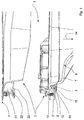
- FIG. 1 shows a fragmentary sectional view of essential elements of a loading door 1 according to the invention prior to their final assembly or joining.
- the loading door 1 comprises a door frame 2, which consists of at least one frame inner part 3 and a (in FIG. 1 not yet joined) frame outer part 4 is formed. Between the frame parts 3, 4, an insert 6 is arranged in the form of a sight glass 7 already inserted into the frame inner part 3, which is held after the joining between the frame parts.
- the sight glass 7 has a circumferential edge 8, which comprises a door frame inside bearing surface 9 and a door frame outer side bearing surface 10.
- the sight glass 7 rests on a previously applied to a circumferential ridge 12 or rolled-up seal 14, which provides with an inside sealing lip 15 in a conventional manner for a sealing closure of a feed opening, not shown, a laundry treatment machine through the loading door 1.
- the support surface 10 is supported in the mounted state of the loading door several doorframe side support areas 20 from, of which in FIG. 1 by way of example only, a support portion of a substantially radially extending rib or ridge 21 is shown.
- At least the support regions 20 are made of a material 22 which is temporarily plastically deformable.
- Both the frame inner part 3 and the frame outer part 4 are made of a thermoplastic material.
- At least the supporting regions 20 are brought into a temporarily plastically deformable state, for example by introducing heat.
- a so-called (in FIG. 1 not shown) heating mirror are introduced, which specifically heats the areas of the frame parts 3, 4 to be softened due to its adapted geometry.
- the sight glass 7 is gripped at its curvature by a suction cup, not shown, and pulled in the direction of arrow 24 vertically downwards. Due to the elastic deformation of the seal 14, the insert 6 (sight glass 7) is thus in a prestressed position, which has a somewhat decreasing effect on the material removal or on the material displacement in the region of the support regions 20.
- the frame parts are preferably made by thermoplastic fusion of connecting webs (as described below in connection with FIGS FIG. 3 even more detailed) and as in FIG. 2 shown connected. How out FIG. 2 can be seen in the region of the support region 20, this is optimally adapted to the geometry of the sight glass 7, ie, on the geometry and the shape of the support surface 10 by the targeted melting described above. After re-hardening of the thermoplastic material, the rib 21 forms a strong and highly resilient support for the sight glass 7. After removal of the bias by removing the suction cup, the door seal 14 resiliently against the direction of the arrow 24 elastically rebound again, resulting in a tight interference fit between support surface 10 and the corresponding cooperating contact surface 25 of the support area 20 leads.
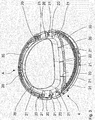
- FIG. 3 shows in further detail the joining principle and the adjustment of the nominal dimension of the door thickness in a perspective view
- the insert 6 (FIG. FIG. 1
- One recognizes several distributed over the circumference holding or support webs 21, of which representative a support web 21 in connection with the FIGS. 1 and 2 has been described in detail.
- the remaining support webs are at their support areas 20 in a corresponding manner to the individual geometry and tolerant thickness of (in FIG. 3 Not shown) use adapted by melting.
- It also recognizes a substantially circumferential, corrugated connecting web 30 and a further connecting web 31, which cooperate with correspondingly formed and complementarily positioned connecting webs of the frame inner part 3 when joining the frame parts.
- FIG. 4 shows in an approximately radial view increases the area A from FIG. 3 , It can be seen a centering post 40 and on both sides arranged posts 41, 42 with an approximately cross-shaped cross section and formed at their respective free end support areas 43, 44. On these support areas 43, 44 is a support surface of a functional insert, such as a signal transmitter pin, using a Frame interior fixed and stored.
- a functional insert such as a signal transmitter pin
- FIG. 5 shows in sectional view with attached insert 50, penetrates the centering post 40 a corresponding receiving bore 52 of a door frame inner part 54, which may be formed integrally with the insert 50 as shown in this embodiment.
- On the inside bearing surfaces 55, 56 of the insert 50 are based on the support areas 43, 44, which made in a corresponding manner by previously done heating the material of the posts 41, 42 temporarily plastically deformable have been prepared and so to a tolerance compensating removal or displacement of the material.
- the insert and thus a functional element 57 is brought into the desired desired position.
Landscapes
- Engineering & Computer Science (AREA)
- Textile Engineering (AREA)
- Wing Frames And Configurations (AREA)
- Securing Of Glass Panes Or The Like (AREA)
- Automobile Manufacture Line, Endless Track Vehicle, Trailer (AREA)
Description
- Die Erfindung liegt auf dem Gebiet der Geräte und Maschinen, die zum Behandeln, insbesondere zum Trocknen und/oder Waschen, von Wäsche oder anderen Gegenständen dienen und die nachfolgend allgemein auch als Wäschebehandlungsmaschinen bezeichnet werden.
- Die Erfindung betrifft ein Verfahren zum Herstellen einer Beschickungstür für eine Wäschebehandlungsmaschine mit einem Türrahmen und einem in dem Türrahmen gehaltenen Schauglas, auf welchem eine Dichtung aufgebracht ist, bei dem der Türrahmen zumindest durch Fügen wenigstens eines Rahmeninnenteils mit wenigstens einem Rahmenaußenteil gebildet wird, und das Schauglas zwischen das Rahmeninnenteil und das Rahmenaußenteil derart eingebracht wird, dass es sich mit wenigstens einer Auflagefläche an mehreren türrahmenseitigen Auflagebereichen abstützt.
- Die Erfindung betrifft ferner eine Beschickungstür für eine Wäschebehandlungsmaschine mit einem Türrahmen, der wenigstens ein Rahmeninnenteil und ein Rahmenaußenteil umfasst, und mit einem in dem Türrahmen angeordneten Schauglas, das wenigstens abschnittsweise an Auflagebereichen des Türrahmens anliegt und auf welchem eine Dichtung aufgebracht ist.
- Ein derartiges Verfahren bzw. eine derartige Beschickungstür gehen aus der Schrift
WO 2007/000645 A1 hervor. - Ein derartiges Verfahren bzw. eine derartige Beschickungstür gehen aus der Schrift
DE 10 2005 023 445 A1 hervor, die auf die optimierte Ausbildung einer Beschickungstür dahingehend gerichtet ist, dass die Ablagerung von Flusen im Bereich einer druckbeaufschlagten Abdichtung der Beschickungstür auch bei fertigungsbedingten Toleranzabweichungen der Türkomponenten vermieden wird. Dazu ist ein Türrahmen vorgesehen, der wenigstens ein Rahmeninnenteil und wenigstens ein mit diesem zusammengefügtes Rahmenaußenteil umfasst. Zwischen den Rahmenteilen ist ein Einsatz gehalten und dazu derart eingebracht, dass er sich mit wenigstens einer Auflagefläche auf mehreren türrahmenseitigen Auflagebereichen abstützt. Bei dem Einsatz handelt es sich um eine bevorzugt topfförmig ausgebildete Glasscheibe (Schauglas), deren Rand in einem von den Rahmenteilen gebildeten umlaufenden Spalt oder Aufnahmeraum aufgenommen ist. Dabei ist der Aufnahmeraum so bemessen, dass genügend Spiel vorhanden ist, um fertigungsbedingte Abweichungen im Ist-Maß der Dicke der Glasscheibe sicher auszugleichen. Bei der Herstellung der Beschickungstür wird zwischen dem Rahmeninnenteil und der Glasscheibe eine Dichtung angeordnet, die durch ihre Elastizität und ihren Querschnitt eine sichere Abdichtung gewährleistet und zudem durch eine mehr oder weniger starke axiale Komprimierung die besagten Fertigungstoleranzen des Einsatzes ausgleicht. - Allerdings tritt dadurch je nach Fertigungsgenauigkeit des Einsatzes und damit je nach Komprimierung der Dichtung zwischen dem Rahmeninnenteil und dem Rahmenaußenteil im Mantelbereich der Beschickungstür ein mehr oder weniger großer Spalt auf, der als Verbindungsfuge der Türrahmenteile für den Betrachter erkennbar ist. Dieser Effekt ist unter Designaspekten nicht wünschenswert. Zudem kann bei der bekannten Beschickungstür konstruktionsbedingt die Ist-Dicke des Türrahmens variieren, wenn die Elastizität der Dichtung nicht zur vollständigen Kompensation etwaiger Maßabweichungen der Einsatzdicke ausreicht.
- Vor diesem Hintergrund besteht eine Aufgabe der vorliegenden Erfindung in der Angabe eines Verfahrens zum Herstellen einer Beschickungstür bzw. in der Schaffung einer Beschickungstür, durch das bzw. bei der für einen Toleranzausgleich der Einsatzabmessungen derart gesorgt ist, dass die Dicke der Beschickungstür stets in einem vorgegebenen Soll-Maß einstellbar ist und somit auch Designvorgaben dahingehend erfüllt werden können, dass beispielsweise das Rahmeninnenteil und das Rahmenaußenteil an vorgegebenen Kanten fugen- und spaltfrei aufeinander liegen.
- Diese Aufgabe wird erfindungsgemäß hinsichtlich des Verfahrens durch ein Verfahren mit den Merkmalen des entsprechenden unabhängigen Patentanspruchs gelöst.
- Bei dem erfindungsgemäßen Verfahren ist demgemäß vorgesehen, dass zumindest das Material der Auflagebereiche vor dem Fügen der Rahmenteile in einen temporär plastisch verformbaren Zustand gebracht wird, bei eingebrachtem Schauglas Kräfte auf die Auflagebereiche ausgeübt werden, so dass sich diese durch Verformung derart an die Geometrie des Schauglases anpassen, dass ein vorgegebenes Soll-Maß der Türdicke eingestellt wird, wobei die Türdicke die Rahmenteile, das zwischen diesen eingebrachte Schauglas und die Dichtung umfasst, und wobei die Auflagebereiche anschließend wieder in einen unverformbaren (festen) Zustand gebracht und die Rahmenteile gefügt werden.
- Ein erster wesentlicher Vorteil der Erfindung besteht damit darin, dass auch vergleichsweise große Toleranzen insbesondere in den für die Beschickungstürdicke relevanten Abmaßen des Einsatzes in Kauf genommen werden können, weil diese individuell durch Verdrängung, Abtrag oder Verformung des Materials der türrahmenseitigen Auflagebereiche kompensiert werden. Dies wirkt sich auch positiv auf die Fertigungskosten aus, weil dadurch höhere Toleranzen in der Ist-Dicke des Einsatzes akzeptabel sind.
- Das erfindungsgemäße Verfahren zeichnet sich zudem durch eine einfache Realisierbarkeit und Automatisierbarkeit aus, weil vorteilhafterweise die beim Fügen der Türrahmenteile auf diese ausgeübten Kräfte zugleich auch zur Verformung bzw. Formanpassung/Vertikalmaßanpassung der Auflagebereiche dienen können. Nachdem die Auflagebereiche wieder in einen im Wesentlichen unverformbaren bzw. festen Zustand - beispielsweise einen ausgehärteten oder erstarrten Zustand - gebracht worden sind, können diese ihre Abstütz- und Haltefunktionen zuverlässig und in einer optimal an die Form der Auflagefläche des Einsatzes angepassten Geometrie ausüben.
- Damit ist ein Verfahren zum Herstellen einer Beschickungstür angegeben, das auch äußerst anspruchsvollen Vorgaben hinsichtlich der Dickenmaßhaltigkeit der Beschickungstür und der Designvorgaben - z.B. einem spaltlosen Fügen der Türrahmenteile im äußerlich sichtbaren Bereich (beispielsweise an der Türrahmenmantelfläche) - genügt.
- Weitere Einzelheiten, Aspekte und Vorteile der Erfindung sind Gegenstand der abhängigen Patentansprüche, der beigefügten Zeichnung und deren jeweils zugehöriger Beschreibung.
- In einer vorteilhaften Ausgestaltung des erfindungsgemäßen Verfahrens wird der Einsatz während des Fügens in eine vorgespannte, in Bezug auf die Auflagebereiche zurückgezogene Position gebracht und nach Abschluss des Fügens aus dieser wieder entlassen. Dadurch wird eine Vorspannung auf die üblicherweise zwischen Einsätzen wie Schaugläsern und einem Rahmenteil vorgesehene Dichtung ausgeübt und damit eine feste Passung zwischen dem Einsatz und dem jeweiligen Auflagebereich erzeugt. Fertigungstechnisch bevorzugt kann der Einsatz (Schauglas) von einer Saugglocke erfasst und in die Vorspannungsrichtung gezogen werden.
- Die erfindungsgemäße temporäre plastische Verformbarkeit zumindest der Auflagebereiche kann grundsätzlich durch verschiedene physikalische und/oder chemische Methoden realisiert werden. So ist beispielsweise ein Anlösen oder Weichmachen der Auflagebereiche durch ein Lösungsmittel oder durch (thermische) Energiezufuhr denkbar.
- Nach einer vorteilhaften Ausgestaltung des erfindungsgemäßen Verfahrens sind die Auflagebereiche oder besonders bevorzugt das Rahmeninnenteil und das Rahmenaußenteils aus einem thermoplastischen Material hergestellt. Zum Fügen von Rahmeninnenteil und Rahmenaußenteil können diese bevorzugt mit kooperierenden Verbindungsstegen versehen werden, die zusammen mit den Auflagebereichen erwärmt und plastisch verformt bzw. verbunden werden. Dazu kann ein sogenannter Heizspiegel zwischen den Fügepartnern (Rahmeninnenteil und Rahmenaußenteil) positioniert werden, so dass das thermoplastische Material aufgrund der so zugeführten Wärmeenergie anschmilzt. Dann wird der Heizspiegel entfernt und die Rahmenteile werden aufeinander aufgesetzt (gefügt) derart, dass die kooperierenden Verbindungsstege miteinander verschmelzen. Gleichzeitig wird durch den Fügedruck der jeweilige Auflagebereich derart an die Geometrie des Einsatzes bzw. der Auflagefläche angepasst, dass überschüssiges Material verdrängt wird. Damit kann die Beschickungstür fertigungstechnisch besonders elegant und zweckmäßig auf eine vorgegebene Soll-Dicke gebracht werden.
- Die eingangs erwähnte Aufgabe hinsichtlich der Beschickungstür wird erfindungsgemäß durch eine Beschickungstür mit den Merkmalen des entsprechenden unabhängigen Patentanspruchs gelöst.
- Bei der erfindungsgemäßen Beschickungstür ist demgemäß vorgesehen, dass zumindest die Auflagebereiche aus einem temporär plastisch verformbaren Material bestehen und dass die Auflagebereiche durch das Fügen der Rahmenteile plastisch derart verformt sind, dass sich unter Ausgleich von Bauteiletoleranzen des Schauglases ein vorgegebenes Soll-Maß der Türdicke einstellt, wobei die Türdicke die Rahmenteile, das zwischen diesen eingebrachte Schauglas und die Dichtung umfasst.
- Die aus einem temporär plastisch verformbaren Material bestehenden Auflagebereiche erlauben durch das Einsetzen des Einsatzes und das Fügen eine einfache optimierte Anpassung, so dass sich das vorgegebene Soll-Maß der Türdicke einstellt. Dabei bestehen Rahmeninnenteil und Rahmenaußenteil bevorzugt aus einem thermoplastischen Material und weisen kooperierende Verbindungsstege auf.
- Besonders bevorzugt kann der Einsatz eine Glasscheibe oder ein sogenanntes Schauglas sein, das z.B. in an sich bekannter Weise aus einem bevorzugt durchsichtigen Kunststoff oder aus Silikat gefertigt sein kann. Die Vorteile der Erfindung realisieren sich aber auch und/oder bevorzugt bei einem (zusätzlichen weiteren) Einsatz, der ein sich zur Türinnenseite erstreckendes Element, wie beispielsweise ein Signalgeber oder ein Verriegelungselement, umfasst.
- Ausführungsbeispiele der Erfindung sind nachfolgend anhand der beigefügten Zeichnung näher erläutert. Dabei sind in den Figuren der Zeichnung gleiche oder funktionsgleiche Elemente jeweils mit denselben Bezugszeichen versehen. Es zeigen:
- Figur 1
- ausschnittsweise Hauptbestandteile einer Beschickungstür vor dem Fügen,
- Figur 2
- ein Rahmenaußenteil einer Beschickungstür,
- Figur 3
- einen der
Figur 1 entsprechenden Ausschnitt einer Beschickungstür im gefügten Zustand, - Figur 4
- Einzelheiten eines Ausschnitts A eines Rahmenaußenteils aus
Figur 3 und - Figur 5
- in Schnittdarstellung einen Teil des Ausschnitts nach
Figur 4 mit einem eingebrachten Einsatz. -
Figur 1 zeigt ausschnittsweise in Schnittansicht wesentliche Elemente einer erfindungsgemäßen Beschickungstür 1 vor deren endgültiger Montage bzw. Fügung. Die Beschickungstür 1 umfasst einen Türrahmen 2, der von wenigstens einem Rahmeninnenteil 3 und einem (inFigur 1 noch nicht gefügten) Rahmenaußenteil 4 gebildet wird. Zwischen den Rahmenteilen 3, 4 ist ein Einsatz 6 in Form eines bereits in das Rahmeninnenteil 3 eingesetzten Schauglases 7 angeordnet, der nach dem Fügen zwischen den Rahmenteilen gehalten ist. Das Schauglas 7 weist einen umlaufenden Rand 8 auf, der eine türrahmeninnenseitige Auflagefläche 9 und eine türrahmenaußenseitige Auflagefläche 10 umfasst. Mit der Auflagefläche 9 liegt das Schauglas 7 auf einer zuvor auf einen umlaufenden Steg 12 aufgebrachte oder aufgekrempelte Dichtung 14 auf, die mit einer innenseitigen Dichtlippe 15 in an sich bekannter Weise für einen dichtenden Verschluss einer nicht dargestellten Beschickungsöffnung einer Wäschebehandlungsmaschine durch die Beschickungstür 1 sorgt. Die Auflagefläche 10 stützt sich im montierten Zustand der Beschickungstür auf mehreren türrahmenseitigen Auflagebereichen 20 ab, von denen inFigur 1 nur beispielhaft ein Auflagebereich einer sich im Wesentlichen radial erstreckenden Rippe oder eines Steges 21 gezeigt ist. - Zumindest die Auflagebereiche 20 sind aus einem Material 22 hergestellt, das temporär plastisch verformbar ist. Im bevorzugt dargestellten Ausführungsbeispiel nach
Figur 1 sind sowohl das Rahmeninnenteil 3 als auch das Rahmenaußenteil 4 aus einem thermoplastischen Kunststoff hergestellt. Vor der Montage bzw. dem Fügen der Rahmenteile werden zumindest die Auflagebereiche 20 beispielsweise durch Wärmeeinbringung in einen temporär plastisch verformbaren Zustand gebracht. Dazu kann - bevorzugt bevor der Einsatz 6 in das Rahmeninnenteil 3 eingesetzt wird - zwischen die Rahmenteile 3, 4 ein sogenannter (inFigur 1 nicht gezeigter) Heizspiegel eingebracht werden, der aufgrund seiner angepassten Geometrie die zu erweichenden Bereiche der Rahmenteile 3, 4 gezielt erwärmt. Anschließend wird das Schauglas 7 an seiner Wölbung von einer nicht dargestellten Saugglocke gegriffen und in Pfeilrichtung 24 senkrecht nach unten gezogen. Aufgrund der elastischen Deformation der Dichtung 14 befindet sich der Einsatz 6 (Schauglas 7) damit in einer vorgespannten Position, was sich auf den Materialabtrag bzw. auf die Materialverdrängung im Bereich der Auflagebereiche 20 etwas mindernd auswirkt. - Bevorzugt werden die Rahmenteile durch thermoplastisches Anschmelzen von Verbindungsstegen (wie nachfolgend im Zusammenhang mit
Figur 3 noch detaillierter gezeigt) gefügt und wie inFigur 2 dargestellt verbunden. Wie ausFigur 2 im Bereich des Auflagebereichs 20 ersichtlich, ist dieser durch das zuvor beschriebene gezielte Anschmelzen optimal an die Geometrie des Schauglases 7, d.h. an dessen Geometrie und die Form der Auflagefläche 10, angepasst. Nach dem Wiedererhärten des thermoplastischen Materials bildet die Rippe 21 eine feste und hochbelastbare Abstützung für das Schauglas 7. Nach Entfernen der Vorspannung durch Entfernen der Saugglocke federt die Türdichtung 14 entgegen der Pfeilrichtung 24 elastisch wieder etwas auf, was zu einem festen Presssitz zwischen Auflagefläche 10 und der entsprechenden kooperierenden Anlagefläche 25 des Auflagebereiches 20 führt. Durch diese individuelle Anpassung der Auflagebereiche 20 an die jeweilige, toleranzbehaftete aktuelle Dicke 26 des Schauglases 7 - durch entsprechenden Materialabtrag oder Materialverdrängung aus dem Auflagebereich - kann stets eine Sollabmessung oder Soll-Dicke 28, die inFigur 2 beispielhaft auf den Auflagepunkt der Dichtung 14 bezogen ist, eingestellt werden und insbesondere eine spaltfreie Verbindung der Rahmenteile 3, 4 sichergestellt werden. -
Figur 3 zeigt zur weiteren Verdeutlichung des Fügeprinzips und der Einstellung des Sollmaßes der Türdicke in perspektivischer Ansicht die dem Einsatz 6 (Figur 1 ) zugewandte Struktur des Rahmenaußenteils 4. Man erkennt mehrere über den Umfang verteilte Halte- oder Auflagestege 21, von denen stellvertretend ein Auflagesteg 21 im Zusammenhang mit denFiguren 1 und2 ausführlich beschrieben wurde. Die übrigen Auflagestege werden an ihren Auflagebereichen 20 in entsprechender Weise an die individuelle Geometrie und toleranzbehaftete Dicke des (inFigur 3 nicht dargestellten) Einsatzes durch Anschmelzen angepasst. Man erkennt ferner einen im Wesentlichen umlaufenden, gewellt ausgebildeten Verbindungssteg 30 und einen weiteren Verbindungssteg 31, die mit entsprechend ausgebildeten und komplementär positionierten Verbindungsstegen des Rahmeninnenteils 3 beim Fügen der Rahmenteile kooperieren. Dabei werden die Stegkämme der kooperierenden Verbindungsstege durch den erwähnten Heizspiegel gleichzeitig angeschmolzen, bevor der Einsatz eingelegt wird. Anschließend werden dann wie bereits beschrieben die Rahmenteile unter Festlegung des Einsatzes über die Verbindungsstege 30, 31 mit den kooperierenden Verbindungsstegen verbunden. Selbstverständlich sind auch andere Verbindungsmöglichkeiten der Rahmenteile in Form von Klebe- oder Schraubverbindungen denkbar. -
Figur 4 zeigt in etwa radialer Ansicht vergrößert den Bereich A ausFigur 3 . Man erkennt einen Zentrierpfosten 40 und beiderseits angeordnete Pfosten 41, 42 mit einem annähernd kreuzförmigen Querschnitt und mit an ihrem jeweiligen freien Ende ausgebildeten Auflagebereichen 43, 44. Auf diesen Auflagebereichen 43, 44 ist eine Auflagefläche eines funktionellen Einsatzes, wie beispielsweise eines Signalgeberstiftes, mithilfe eines Rahmeninnenteils festgelegt und gelagert. - Wie dazu
Figur 5 in Schnittdarstellung mit aufgesetztem Einsatz 50 zeigt, durchdringt der Zentrierpfosten 40 eine entsprechende Aufnahmebohrung 52 eines Türrahmeninnenteils 54, das wie in diesem Ausführungsbeispiel gezeigt einstückig mit dem Einsatz 50 ausgebildet sein kann. Innenseitige Auflageflächen 55, 56 des Einsatzes 50 stützen sich auf den Auflagebereichen 43, 44 ab, die in entsprechender Weise durch zuvor erfolgtes Erwärmen des Materials der Pfosten 41, 42 temporär plastisch verformbar gemacht worden sind und so zu einem toleranzausgleichenden Entfernen bzw. Verdrängen des Materials vorbereitet worden sind. Dadurch ist der Einsatz und damit ein Funktionselement 57 in die gewünschte Sollposition gebracht. -
- 1
- Beschickungstür
- 2
- Türrahmen
- 3
- Rahmeninnenteil
- 4
- Rahmenaußenteil
- 6
- Einsatz
- 7
- Schauglas
- 8
- Rand
- 9
- Auflagefläche
- 10
- Auflagefläche
- 12
- Steg
- 14
- Dichtung
- 15
- Dichtlippe
- 20
- Auflagebereiche
- 21
- Rippe
- 24
- Pfeilrichtung
- 25
- Anlagefläche
- 26
- Dicke
- 28
- Soll-Maß
- 30
- Verbindungssteg
- 31
- Verbindungssteg
- 40
- Zentrierpfosten
- 41, 42
- Pfosten
- 43, 44
- Auflagebereiche
- 50
- Einsatz
- 52
- Aufnahmebohrung
- 54
- Türrahmeninnenteil
- 55, 56
- Auflageflächen
- 57
- Funktionselement
- A
- Bereich
Claims (5)
- Verfahren zum Herstellen einer Beschickungstür (1) für eine Wäschebehandlungsmaschine mit einem Türrahmen (2) und einem in dem Türrahmen (2) gehaltenen Schauglas (6) auf welchem eine Dichtung (14) aufgebracht ist, bei dem der Türrahmen (2) zumindest durch Fügen wenigstens eines Rahmeninnenteils (3) mit wenigstens einem Rahmenaußenteil (4) gebildet wird und
das Schauglas (6) zwischen das Rahmeninnenteil (3) und das Rahmenaußenteil (4) derart eingebracht wird, dass es sich mit wenigstens einer Auflagefläche (10) auf mehreren türrahmenseitigen Auflagebereichen (20) abstützt,
dadurch gekennzeichnet, dass
zumindest das Material (22) der Auflagebereiche (20) vor dem Fügen der Rahmenteile (3, 4) in einen temporär plastisch verformbaren Zustand gebracht wird, bei eingebrachtem Schauglas (6) Kräfte auf die Auflagebereiche (20) ausgeübt werden, so dass sich diese durch Verformung derart an die Geometrie des Schauglases (6) anpassen, dass ein vorgegebenes Soll-Maß der (28) Türdicke eingestellt wird, wobei die Türdicke die Rahmenteile (3, 4), das zwischen diesen eingebrachte Schauglas (6) und die Dichtung (14) umfasst; und
die Auflagebereiche (20) anschließend wieder in einen unverformbaren Zustand gebracht und die Rahmenteile (3,4) gefügt werden. - Verfahren nach Anspruch 1, dadurch gekennzeichnet, dass das Rahmeninnenteil (3) und das Rahmenaußenteil (4) aus einem thermoplastischen Material (22) hergestellt und mit kooperierenden Verbindungsstegen (30, 31) versehen werden, die zusammen mit den Auflagebereichen (20) erwärmt werden.
- Verfahren nach wenigstens einem der Ansprüche 1 und 2, dadurch gekennzeichnet, dass das Material (22) der Auflagebereiche (20) thermoplastisch ist und dass die Auflagebereiche durch einen Heizspiegel erwärmt und dadurch temporär in den plastisch verformbaren Zustand gebracht werden.
- Beschickungstür für eine Wäschebehandlungsmaschine mit einem Türrahmen (2), der wenigstens ein Rahmeninnenteil (3) und ein Rahmenaußenteil (4) umfasst, und
mit einem in dem Türrahmen (2) angeordneten Schauglas (6), das wenigstens abschnittsweise an Auflagebereichen (20) des Türrahmens (2) anliegt und auf welchem eine Dichtung (14) aufgebracht ist,
dadurch gekennzeichnet, dass
zumindest die Auflagebereiche (20) aus einem temporär plastisch verformbaren Material (22) bestehen und
die Auflagebereiche (20) durch das Fügen der Rahmenteile (3, 4) plastisch derart verformt sind, dass sich unter Ausgleich von Bauteiltoleranzen des Schauglases (6) ein vorgegebenes Soll-Maß (28) der Türdicke einstellt, wobei die Türdicke die Rahmenteile (3, 4), das zwischen diesen eingebrachte Schauglas (6) und die Dichtung (14) umfasst. - Beschickungstür nach Anspruch 4, dadurch gekennzeichnet, dass Rahmeninnenteil (3) und Rahmenaußenteil (4) aus einem thermoplastischen Material (22) bestehen und kooperierende Verbindungsstege (30, 31) aufweisen.
Applications Claiming Priority (2)
| Application Number | Priority Date | Filing Date | Title |
|---|---|---|---|
| DE102011078918A DE102011078918A1 (de) | 2011-07-11 | 2011-07-11 | Verfahren zum Herstellen einer Beschickungstür sowie Beschickungstür für eine Wäschebehandlungsmaschine |
| PCT/EP2012/062306 WO2013007510A1 (de) | 2011-07-11 | 2012-06-26 | Verfahren zum herstellen einer beschickungstür sowie beschickungstür für eine wäschebehandlungsmaschine |
Publications (2)
| Publication Number | Publication Date |
|---|---|
| EP2732089A1 EP2732089A1 (de) | 2014-05-21 |
| EP2732089B1 true EP2732089B1 (de) | 2016-09-21 |
Family
ID=46331356
Family Applications (1)
| Application Number | Title | Priority Date | Filing Date |
|---|---|---|---|
| EP12729164.9A Active EP2732089B1 (de) | 2011-07-11 | 2012-06-26 | Verfahren zum herstellen einer beschickungstür sowie beschickungstür für eine wäschebehandlungsmaschine |
Country Status (5)
| Country | Link |
|---|---|
| EP (1) | EP2732089B1 (de) |
| CN (1) | CN103649404B (de) |
| DE (1) | DE102011078918A1 (de) |
| PL (1) | PL2732089T3 (de) |
| WO (1) | WO2013007510A1 (de) |
Families Citing this family (1)
| Publication number | Priority date | Publication date | Assignee | Title |
|---|---|---|---|---|
| DE102024104001A1 (de) * | 2024-02-13 | 2025-08-14 | Miele & Cie. Kg | Tür für eine Wäschebehandlungsmaschine, Wäschebehandlungsmaschine und Verfahren zur Herstellung einer Wäschebehandlungsmaschine |
Family Cites Families (15)
| Publication number | Priority date | Publication date | Assignee | Title |
|---|---|---|---|---|
| DE10031172A1 (de) * | 2000-06-27 | 2002-01-10 | Bsh Bosch Siemens Hausgeraete | Dichtungseinrichtung |
| DE10031171A1 (de) * | 2000-06-27 | 2002-01-10 | Bsh Bosch Siemens Hausgeraete | Bullaugen-Fenster für eine Frontlader-Trommelwaschmaschine |
| DE10053413A1 (de) * | 2000-10-27 | 2002-05-08 | Bsh Bosch Siemens Hausgeraete | Bullaugentür für eine von vorn beschickbare Trommelwaschmaschine |
| US20050262681A1 (en) * | 2004-06-01 | 2005-12-01 | Lg Electronics Inc. | Door of drum washer and assembling method for the same |
| KR101125402B1 (ko) * | 2004-07-19 | 2012-03-27 | 엘지전자 주식회사 | 드럼 세탁기의 도어 구조 |
| DE102005023445A1 (de) | 2005-05-20 | 2006-11-23 | BSH Bosch und Siemens Hausgeräte GmbH | Tür für eine Wäschetrockenmaschine |
| ITTO20050453A1 (it) * | 2005-06-29 | 2006-12-30 | Indesit Co Spa | Sportello per elettrodomestico in particolare per macchina, lavasciuga o asciugabiancheria a carica frontale o sostanzialmente frontale |
| JP4551299B2 (ja) * | 2005-09-08 | 2010-09-22 | パナソニック株式会社 | ドラム式洗濯機 |
| CN101497242A (zh) * | 2008-01-28 | 2009-08-05 | 株式会社比体昂恩得丕 | 滚筒洗衣机门制造方法 |
| CN201245778Y (zh) * | 2008-08-13 | 2009-05-27 | 松下电化住宅设备机器(杭州)有限公司 | 滚筒洗衣机机门 |
| JP4845058B2 (ja) * | 2008-08-28 | 2011-12-28 | シャープ株式会社 | ドラム式洗濯機 |
| CN201411566Y (zh) * | 2009-05-13 | 2010-02-24 | 松下家电研究开发(杭州)有限公司 | 机门结构及采用该机门结构的滚筒洗衣机 |
| EP2253756B1 (de) * | 2009-05-22 | 2014-05-14 | Electrolux Home Products Corporation N.V. | Herstellungsverfahren für eine Türeinheit, insbesondere eine Türeinheit für eine Wäschebehandlungsmaschine |
| JP5618517B2 (ja) * | 2009-09-30 | 2014-11-05 | 日立アプライアンス株式会社 | 電気洗濯機 |
| EP2405051B1 (de) * | 2010-07-06 | 2014-07-02 | Electrolux Home Products Corporation N.V. | Glasbullaugenfenster für ein Wasch- und/oder Trocknungsgerät |
-
2011
- 2011-07-11 DE DE102011078918A patent/DE102011078918A1/de not_active Withdrawn
-
2012
- 2012-06-26 PL PL12729164T patent/PL2732089T3/pl unknown
- 2012-06-26 WO PCT/EP2012/062306 patent/WO2013007510A1/de not_active Ceased
- 2012-06-26 CN CN201280034268.6A patent/CN103649404B/zh active Active
- 2012-06-26 EP EP12729164.9A patent/EP2732089B1/de active Active
Also Published As
| Publication number | Publication date |
|---|---|
| DE102011078918A1 (de) | 2013-01-17 |
| CN103649404B (zh) | 2016-03-30 |
| EP2732089A1 (de) | 2014-05-21 |
| RU2014101773A (ru) | 2015-11-27 |
| PL2732089T3 (pl) | 2017-02-28 |
| CN103649404A (zh) | 2014-03-19 |
| WO2013007510A1 (de) | 2013-01-17 |
Similar Documents
| Publication | Publication Date | Title |
|---|---|---|
| DE102014114086B4 (de) | System zur elastisch gemittelten Ausrichtung | |
| EP2486288B1 (de) | Verbindung zwischen zwei bauteilen aus verstärktem kunststoff und verfahren zu ihrer herstellung | |
| DE102008010197B4 (de) | Verfahren zum Verbinden von zwei Rumpfsektionen unter Schaffung eines Querstoßes sowie Querstoßverbindung | |
| DE102012019849B4 (de) | Bauteil mit Dichtstopfen sowie Verfahren zum Einformen eines Bauteileinsatzes | |
| DE102009044210A1 (de) | Dübel und Verfahren zur Montage eines Dübels in eine Leichtbauplatte | |
| DE102008021788A1 (de) | Verfahren zum Reparieren einer Flugzeugkomponente | |
| WO2013135414A1 (de) | Bauteilverbindung | |
| EP2860407B1 (de) | Strukturbauteil | |
| EP3100848B1 (de) | Faserkunststoffverbund-bauteil mit verdichteten fasern und verfahren zu dessen herstellung | |
| DE102014112003A1 (de) | Montageeinheit und Verfahren zu deren Herstellung | |
| DE19753111A1 (de) | Lagerbuchse mit Mittelbund sowie deren Verwendung und Herstellungsverfahren | |
| EP3134254A1 (de) | Verfahren zum verbinden von verbindungsabschnitten von wenigstens zwei bauteilen | |
| EP3339632A1 (de) | Anschluss- und befestigungseinheit für einen blitzrezeptor zur integration in ein windenergieanlagenrotorblatt | |
| DE102016124078B3 (de) | Verbindungsanordnung für die Verbindung von zwei Schaltschrankrahmengestellen | |
| WO2013007510A1 (de) | Verfahren zum herstellen einer beschickungstür sowie beschickungstür für eine wäschebehandlungsmaschine | |
| EP1394420A2 (de) | Einsatzteil für eine Wandöffnung, insbesondere an einer Fahrzeugkarosserie | |
| DE102016225911B4 (de) | Nockenwellenmodul sowie Verfahren zum Herstellen eines Nockenwellenmoduls | |
| DE102017222950A1 (de) | Gehäuse für einen Gassack eines Fahrzeuginsassen-Rückhaltesystems eines Kraftfahrzeugs, formgebende Vorrichtung und Verfahren zum Herstellen eines derartigen Gehäuses | |
| EP2639395B1 (de) | Rahmenprofil, Flügel eines Fensters oder einer Tür und Verfahren zur Herstellung desselben | |
| DE102012015606A1 (de) | Abstandselement und Verfahren zur relativen Ausrichtung | |
| EP2642059A1 (de) | Verfahren zum Verstärken eines Kunststoff-Hohlkammerprofils | |
| DE102005043997B4 (de) | Bauteilsatz zum Bilden eines zusammengesetzten Bauteils und Einsatzbauteil | |
| DE102024001349A1 (de) | Verbindung zwischen einer Außenhaut-Beplankung und eines Fahrzeug-Rohbaus | |
| WO2017067538A1 (de) | Schweissbaugruppe und verfahren zur herstellung einer schweissbaugruppe | |
| DE102016002958A1 (de) | Vorrichtung zum Befestigen einer Leitung, Dichteinsatz |
Legal Events
| Date | Code | Title | Description |
|---|---|---|---|
| PUAI | Public reference made under article 153(3) epc to a published international application that has entered the european phase |
Free format text: ORIGINAL CODE: 0009012 |
|
| 17P | Request for examination filed |
Effective date: 20140211 |
|
| AK | Designated contracting states |
Kind code of ref document: A1 Designated state(s): AL AT BE BG CH CY CZ DE DK EE ES FI FR GB GR HR HU IE IS IT LI LT LU LV MC MK MT NL NO PL PT RO RS SE SI SK SM TR |
|
| DAX | Request for extension of the european patent (deleted) | ||
| RAP1 | Party data changed (applicant data changed or rights of an application transferred) |
Owner name: BSH HAUSGERAETE GMBH |
|
| 17Q | First examination report despatched |
Effective date: 20150814 |
|
| GRAP | Despatch of communication of intention to grant a patent |
Free format text: ORIGINAL CODE: EPIDOSNIGR1 |
|
| INTG | Intention to grant announced |
Effective date: 20160513 |
|
| GRAS | Grant fee paid |
Free format text: ORIGINAL CODE: EPIDOSNIGR3 |
|
| GRAA | (expected) grant |
Free format text: ORIGINAL CODE: 0009210 |
|
| AK | Designated contracting states |
Kind code of ref document: B1 Designated state(s): AL AT BE BG CH CY CZ DE DK EE ES FI FR GB GR HR HU IE IS IT LI LT LU LV MC MK MT NL NO PL PT RO RS SE SI SK SM TR |
|
| REG | Reference to a national code |
Ref country code: GB Ref legal event code: FG4D Free format text: NOT ENGLISH |
|
| REG | Reference to a national code |
Ref country code: CH Ref legal event code: EP |
|
| REG | Reference to a national code |
Ref country code: AT Ref legal event code: REF Ref document number: 831152 Country of ref document: AT Kind code of ref document: T Effective date: 20161015 |
|
| REG | Reference to a national code |
Ref country code: IE Ref legal event code: FG4D Free format text: LANGUAGE OF EP DOCUMENT: GERMAN |
|
| REG | Reference to a national code |
Ref country code: DE Ref legal event code: R096 Ref document number: 502012008311 Country of ref document: DE |
|
| REG | Reference to a national code |
Ref country code: LT Ref legal event code: MG4D Ref country code: NL Ref legal event code: MP Effective date: 20160921 |
|
| PG25 | Lapsed in a contracting state [announced via postgrant information from national office to epo] |
Ref country code: NO Free format text: LAPSE BECAUSE OF FAILURE TO SUBMIT A TRANSLATION OF THE DESCRIPTION OR TO PAY THE FEE WITHIN THE PRESCRIBED TIME-LIMIT Effective date: 20161221 Ref country code: FI Free format text: LAPSE BECAUSE OF FAILURE TO SUBMIT A TRANSLATION OF THE DESCRIPTION OR TO PAY THE FEE WITHIN THE PRESCRIBED TIME-LIMIT Effective date: 20160921 Ref country code: RS Free format text: LAPSE BECAUSE OF FAILURE TO SUBMIT A TRANSLATION OF THE DESCRIPTION OR TO PAY THE FEE WITHIN THE PRESCRIBED TIME-LIMIT Effective date: 20160921 Ref country code: LT Free format text: LAPSE BECAUSE OF FAILURE TO SUBMIT A TRANSLATION OF THE DESCRIPTION OR TO PAY THE FEE WITHIN THE PRESCRIBED TIME-LIMIT Effective date: 20160921 |
|
| PG25 | Lapsed in a contracting state [announced via postgrant information from national office to epo] |
Ref country code: SE Free format text: LAPSE BECAUSE OF FAILURE TO SUBMIT A TRANSLATION OF THE DESCRIPTION OR TO PAY THE FEE WITHIN THE PRESCRIBED TIME-LIMIT Effective date: 20160921 Ref country code: NL Free format text: LAPSE BECAUSE OF FAILURE TO SUBMIT A TRANSLATION OF THE DESCRIPTION OR TO PAY THE FEE WITHIN THE PRESCRIBED TIME-LIMIT Effective date: 20160921 Ref country code: GR Free format text: LAPSE BECAUSE OF FAILURE TO SUBMIT A TRANSLATION OF THE DESCRIPTION OR TO PAY THE FEE WITHIN THE PRESCRIBED TIME-LIMIT Effective date: 20161222 Ref country code: LV Free format text: LAPSE BECAUSE OF FAILURE TO SUBMIT A TRANSLATION OF THE DESCRIPTION OR TO PAY THE FEE WITHIN THE PRESCRIBED TIME-LIMIT Effective date: 20160921 |
|
| PG25 | Lapsed in a contracting state [announced via postgrant information from national office to epo] |
Ref country code: RO Free format text: LAPSE BECAUSE OF FAILURE TO SUBMIT A TRANSLATION OF THE DESCRIPTION OR TO PAY THE FEE WITHIN THE PRESCRIBED TIME-LIMIT Effective date: 20160921 Ref country code: EE Free format text: LAPSE BECAUSE OF FAILURE TO SUBMIT A TRANSLATION OF THE DESCRIPTION OR TO PAY THE FEE WITHIN THE PRESCRIBED TIME-LIMIT Effective date: 20160921 |
|
| PG25 | Lapsed in a contracting state [announced via postgrant information from national office to epo] |
Ref country code: SM Free format text: LAPSE BECAUSE OF FAILURE TO SUBMIT A TRANSLATION OF THE DESCRIPTION OR TO PAY THE FEE WITHIN THE PRESCRIBED TIME-LIMIT Effective date: 20160921 Ref country code: SK Free format text: LAPSE BECAUSE OF FAILURE TO SUBMIT A TRANSLATION OF THE DESCRIPTION OR TO PAY THE FEE WITHIN THE PRESCRIBED TIME-LIMIT Effective date: 20160921 Ref country code: PT Free format text: LAPSE BECAUSE OF FAILURE TO SUBMIT A TRANSLATION OF THE DESCRIPTION OR TO PAY THE FEE WITHIN THE PRESCRIBED TIME-LIMIT Effective date: 20170123 Ref country code: ES Free format text: LAPSE BECAUSE OF FAILURE TO SUBMIT A TRANSLATION OF THE DESCRIPTION OR TO PAY THE FEE WITHIN THE PRESCRIBED TIME-LIMIT Effective date: 20160921 Ref country code: BG Free format text: LAPSE BECAUSE OF FAILURE TO SUBMIT A TRANSLATION OF THE DESCRIPTION OR TO PAY THE FEE WITHIN THE PRESCRIBED TIME-LIMIT Effective date: 20161221 Ref country code: IS Free format text: LAPSE BECAUSE OF FAILURE TO SUBMIT A TRANSLATION OF THE DESCRIPTION OR TO PAY THE FEE WITHIN THE PRESCRIBED TIME-LIMIT Effective date: 20170121 Ref country code: CZ Free format text: LAPSE BECAUSE OF FAILURE TO SUBMIT A TRANSLATION OF THE DESCRIPTION OR TO PAY THE FEE WITHIN THE PRESCRIBED TIME-LIMIT Effective date: 20160921 |
|
| REG | Reference to a national code |
Ref country code: DE Ref legal event code: R097 Ref document number: 502012008311 Country of ref document: DE |
|
| PG25 | Lapsed in a contracting state [announced via postgrant information from national office to epo] |
Ref country code: IT Free format text: LAPSE BECAUSE OF FAILURE TO SUBMIT A TRANSLATION OF THE DESCRIPTION OR TO PAY THE FEE WITHIN THE PRESCRIBED TIME-LIMIT Effective date: 20160921 |
|
| PLBE | No opposition filed within time limit |
Free format text: ORIGINAL CODE: 0009261 |
|
| STAA | Information on the status of an ep patent application or granted ep patent |
Free format text: STATUS: NO OPPOSITION FILED WITHIN TIME LIMIT |
|
| PG25 | Lapsed in a contracting state [announced via postgrant information from national office to epo] |
Ref country code: DK Free format text: LAPSE BECAUSE OF FAILURE TO SUBMIT A TRANSLATION OF THE DESCRIPTION OR TO PAY THE FEE WITHIN THE PRESCRIBED TIME-LIMIT Effective date: 20160921 |
|
| 26N | No opposition filed |
Effective date: 20170622 |
|
| PG25 | Lapsed in a contracting state [announced via postgrant information from national office to epo] |
Ref country code: SI Free format text: LAPSE BECAUSE OF FAILURE TO SUBMIT A TRANSLATION OF THE DESCRIPTION OR TO PAY THE FEE WITHIN THE PRESCRIBED TIME-LIMIT Effective date: 20160921 |
|
| PG25 | Lapsed in a contracting state [announced via postgrant information from national office to epo] |
Ref country code: MC Free format text: LAPSE BECAUSE OF FAILURE TO SUBMIT A TRANSLATION OF THE DESCRIPTION OR TO PAY THE FEE WITHIN THE PRESCRIBED TIME-LIMIT Effective date: 20160921 |
|
| REG | Reference to a national code |
Ref country code: CH Ref legal event code: PL |
|
| REG | Reference to a national code |
Ref country code: IE Ref legal event code: MM4A |
|
| REG | Reference to a national code |
Ref country code: FR Ref legal event code: ST Effective date: 20180228 |
|
| PG25 | Lapsed in a contracting state [announced via postgrant information from national office to epo] |
Ref country code: CH Free format text: LAPSE BECAUSE OF NON-PAYMENT OF DUE FEES Effective date: 20170630 Ref country code: LI Free format text: LAPSE BECAUSE OF NON-PAYMENT OF DUE FEES Effective date: 20170630 Ref country code: LU Free format text: LAPSE BECAUSE OF NON-PAYMENT OF DUE FEES Effective date: 20170626 Ref country code: IE Free format text: LAPSE BECAUSE OF NON-PAYMENT OF DUE FEES Effective date: 20170626 |
|
| PG25 | Lapsed in a contracting state [announced via postgrant information from national office to epo] |
Ref country code: FR Free format text: LAPSE BECAUSE OF NON-PAYMENT OF DUE FEES Effective date: 20170630 |
|
| REG | Reference to a national code |
Ref country code: BE Ref legal event code: MM Effective date: 20170630 |
|
| REG | Reference to a national code |
Ref country code: AT Ref legal event code: MM01 Ref document number: 831152 Country of ref document: AT Kind code of ref document: T Effective date: 20170626 |
|
| PG25 | Lapsed in a contracting state [announced via postgrant information from national office to epo] |
Ref country code: BE Free format text: LAPSE BECAUSE OF NON-PAYMENT OF DUE FEES Effective date: 20170630 |
|
| PG25 | Lapsed in a contracting state [announced via postgrant information from national office to epo] |
Ref country code: MT Free format text: LAPSE BECAUSE OF FAILURE TO SUBMIT A TRANSLATION OF THE DESCRIPTION OR TO PAY THE FEE WITHIN THE PRESCRIBED TIME-LIMIT Effective date: 20160921 |
|
| PG25 | Lapsed in a contracting state [announced via postgrant information from national office to epo] |
Ref country code: AL Free format text: LAPSE BECAUSE OF FAILURE TO SUBMIT A TRANSLATION OF THE DESCRIPTION OR TO PAY THE FEE WITHIN THE PRESCRIBED TIME-LIMIT Effective date: 20160921 |
|
| PG25 | Lapsed in a contracting state [announced via postgrant information from national office to epo] |
Ref country code: AT Free format text: LAPSE BECAUSE OF NON-PAYMENT OF DUE FEES Effective date: 20170626 |
|
| PG25 | Lapsed in a contracting state [announced via postgrant information from national office to epo] |
Ref country code: HU Free format text: LAPSE BECAUSE OF FAILURE TO SUBMIT A TRANSLATION OF THE DESCRIPTION OR TO PAY THE FEE WITHIN THE PRESCRIBED TIME-LIMIT; INVALID AB INITIO Effective date: 20120626 |
|
| PG25 | Lapsed in a contracting state [announced via postgrant information from national office to epo] |
Ref country code: CY Free format text: LAPSE BECAUSE OF NON-PAYMENT OF DUE FEES Effective date: 20160921 |
|
| PG25 | Lapsed in a contracting state [announced via postgrant information from national office to epo] |
Ref country code: MK Free format text: LAPSE BECAUSE OF FAILURE TO SUBMIT A TRANSLATION OF THE DESCRIPTION OR TO PAY THE FEE WITHIN THE PRESCRIBED TIME-LIMIT Effective date: 20160921 |
|
| PG25 | Lapsed in a contracting state [announced via postgrant information from national office to epo] |
Ref country code: TR Free format text: LAPSE BECAUSE OF FAILURE TO SUBMIT A TRANSLATION OF THE DESCRIPTION OR TO PAY THE FEE WITHIN THE PRESCRIBED TIME-LIMIT Effective date: 20160921 |
|
| PG25 | Lapsed in a contracting state [announced via postgrant information from national office to epo] |
Ref country code: HR Free format text: LAPSE BECAUSE OF FAILURE TO SUBMIT A TRANSLATION OF THE DESCRIPTION OR TO PAY THE FEE WITHIN THE PRESCRIBED TIME-LIMIT Effective date: 20160921 |
|
| REG | Reference to a national code |
Ref country code: DE Ref legal event code: R084 Ref document number: 502012008311 Country of ref document: DE |
|
| PGFP | Annual fee paid to national office [announced via postgrant information from national office to epo] |
Ref country code: GB Payment date: 20230622 Year of fee payment: 12 |
|
| GBPC | Gb: european patent ceased through non-payment of renewal fee |
Effective date: 20240626 |
|
| PG25 | Lapsed in a contracting state [announced via postgrant information from national office to epo] |
Ref country code: GB Free format text: LAPSE BECAUSE OF NON-PAYMENT OF DUE FEES Effective date: 20240626 |
|
| PGFP | Annual fee paid to national office [announced via postgrant information from national office to epo] |
Ref country code: DE Payment date: 20250630 Year of fee payment: 14 |
|
| PGFP | Annual fee paid to national office [announced via postgrant information from national office to epo] |
Ref country code: PL Payment date: 20250618 Year of fee payment: 14 |