EP2731759B1 - Razor cartridge - Google Patents
Razor cartridge Download PDFInfo
- Publication number
- EP2731759B1 EP2731759B1 EP13745755.2A EP13745755A EP2731759B1 EP 2731759 B1 EP2731759 B1 EP 2731759B1 EP 13745755 A EP13745755 A EP 13745755A EP 2731759 B1 EP2731759 B1 EP 2731759B1
- Authority
- EP
- European Patent Office
- Prior art keywords
- blade
- leading
- trailing
- hair
- edge
- Prior art date
- Legal status (The legal status is an assumption and is not a legal conclusion. Google has not performed a legal analysis and makes no representation as to the accuracy of the status listed.)
- Active
Links
- 238000000576 coating method Methods 0.000 claims description 15
- 239000011248 coating agent Substances 0.000 claims description 14
- 125000006850 spacer group Chemical group 0.000 claims description 5
- 210000004209 hair Anatomy 0.000 description 121
- 239000000835 fiber Substances 0.000 description 26
- 230000000694 effects Effects 0.000 description 7
- 238000000034 method Methods 0.000 description 7
- 230000001815 facial effect Effects 0.000 description 5
- 238000005259 measurement Methods 0.000 description 5
- 230000001419 dependent effect Effects 0.000 description 3
- 230000003993 interaction Effects 0.000 description 2
- 230000001050 lubricating effect Effects 0.000 description 2
- 239000000463 material Substances 0.000 description 2
- 239000004033 plastic Substances 0.000 description 2
- 230000000052 comparative effect Effects 0.000 description 1
- 230000007613 environmental effect Effects 0.000 description 1
- 230000003695 hair diameter Effects 0.000 description 1
- 230000003694 hair properties Effects 0.000 description 1
- 238000000338 in vitro Methods 0.000 description 1
- 230000007794 irritation Effects 0.000 description 1
- 238000002955 isolation Methods 0.000 description 1
- 239000002184 metal Substances 0.000 description 1
- 239000002991 molded plastic Substances 0.000 description 1
- 230000000149 penetrating effect Effects 0.000 description 1
- 230000035515 penetration Effects 0.000 description 1
- 230000000750 progressive effect Effects 0.000 description 1
- 210000004761 scalp Anatomy 0.000 description 1
Images


Classifications
-
- B—PERFORMING OPERATIONS; TRANSPORTING
- B26—HAND CUTTING TOOLS; CUTTING; SEVERING
- B26B—HAND-HELD CUTTING TOOLS NOT OTHERWISE PROVIDED FOR
- B26B21/00—Razors of the open or knife type; Safety razors or other shaving implements of the planing type; Hair-trimming devices involving a razor-blade; Equipment therefor
- B26B21/40—Details or accessories
- B26B21/4012—Housing details, e.g. for cartridges
- B26B21/4031—Housing details, e.g. for cartridges characterised by special geometric shaving parameters, e.g. blade span or exposure
-
- B—PERFORMING OPERATIONS; TRANSPORTING
- B26—HAND CUTTING TOOLS; CUTTING; SEVERING
- B26B—HAND-HELD CUTTING TOOLS NOT OTHERWISE PROVIDED FOR
- B26B21/00—Razors of the open or knife type; Safety razors or other shaving implements of the planing type; Hair-trimming devices involving a razor-blade; Equipment therefor
- B26B21/54—Razor-blades
- B26B21/56—Razor-blades characterised by the shape
- B26B21/565—Bent razor blades; Razor blades with bent carriers
Description
- The present invention relates to wet shaving safety razors and more particularly to a safety razor blade unit having multiple blades.
- Wet shaving razors have evolved over the years to include a multiplicity of blades with the goal of increasing the closeness of a shave that is achieved while also providing a comfortable shaving experience. One of the main drivers of closeness in shaving is an effect called hysteresis. The hysteresis effect is the meta-stable extension of hair that occurs after a hair is cut during shaving. In present day razors, sharp cutting edges of the cartridge engage with individual hairs during a shaving stroke, exerting a force on the hairs and causing them to be lifted out of the follicle as the razor is moved across the surface of the skin. Once the hair has been cut and the force is removed, the hair retracts back into the skin. There is a time lag before the hair fully retracts and in this time, if a second blade is positioned close enough, it will engage and cut the hair. This concept of consecutive blades cutting hairs before they have fully retracted into the skin is known as "hysteresis cutting". If the second and consecutive blades also engage and pull hairs while cutting, it becomes possible to get a significantly closer cut than when using a single blade razor.
-
WO95/09071 - According to a first aspect of the invention, there is provided a razor comprising a housing, a guard located at a front of the housing and a cap located at a rear of the housing, a skin contact plane tangential to the guard and the cap, a blade couplet disposed in the housing between the guard and the cap, the blade couplet being formed of a leading blade having a leading edge and a trailing blade having a trailing edge, the leading and trailing edges being directed towards the front of the housing, and the leading blade is positioned between the trailing blade and the guard, towards the front of the housing wherein i) there is a span of between 25 µm and 850 µm between the leading edge and the trailing edge, ii) the leading edge has an exposure of between 25 µm and 500 µm below the skin contact plane, iii) the trailing edge is positioned in line with or above the leading edge and has an exposure of between 150 µm above the skin contact plane to 300 µm below the skin contact plane, and iv) the difference in exposure between the leading edge and the trailing edge is equal to or less than the span between the leading edge and the trailing edge.
- Embodiments of the invention will hereinafter be described, by way of example, with reference to the accompanying drawings, in which:
-
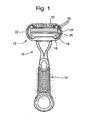
FIG. 1 is a perspective view of an embodiment of a razor according to the present invention. -
FIG. 2 is a schematic cross-sectional view through an embodiment of a cartridge of the present invention; -
FIG. 3 is a schematic view of the cartridge shown inFIG. 2 without additional blades and illustrating different dimensions and measurements used in the present invention; -
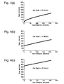
FIG. 4(a), 4(b) and 4(c) illustrate the relationship between the span between adjacent blade edges and the resulting extension of hair, when using an embodiment of the present invention; -
FIG. 5(a), 5(b), 5(c) ,5(d), 5(e) and 5(f) show schematically the interaction between a razor of the present invention and hair when in use; -
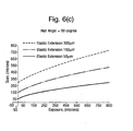
FIG. 6(a), 6(b) and6(c) show data representing the relationship between different geometries of blades in a cartridge of the present invention; -
FIG. 7 shows an alternative embodiment of the blade couplet of the present invention; -
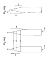
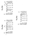
FIG. 8(a) and 8(b) show embodiments of different blade options of the present invention; -
FIG. 9(a), 9(b) and 9(c) show alternative embodiments of the layout of blades shown in the razor ofFIG. 2 ; -
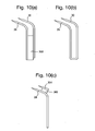
FIG. 10(a), 10(b) and 10(c) , show alternative assembly options for the blade couplet of the present invention; -
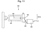
FIG. 11 shows schematically a single fiber cutting rig for measuring the cutting force of blades of the present invention. - The invention is applicable to razor cartridges in general that are used in a wet shaving system.
-
Figure 1 shows awet shaving razor 10 formed of arazor cartridge 12 attached to ahandle 14. The razor cartridge is formed of ahousing 16 having afront wall 18, arear wall 20 and first and secondopposing side walls Figure 2 ) formed of a leadingblade 28 and atrailing blade 30 is mounted within thehousing 16. Each of the leadingblade 28 andtrailing blade 30 has acutting edge opposing side walls additional blades 36 are disposed in thehousing 16, each additional blade having a cutting edge 38 (Figure 2 ) extending between the first and secondopposing side walls - Hysteresis cutting is dependent on the proximity of blade edges to one another in a cartridge; the first blade makes contact with a hair and pulls it from the skin surface and the adjacent blade should be near enough the first blade that it engages with the hair before it has time to fully retract into the skin surface. The present inventors have discovered that to fully capitalize on the extension of a hair while it is being cut by a first blade, it would be desirable for the next/second blade to cut the hair before it has retracted at all. This is most easily achieved if two consecutive blades make contact with the same hair. In an embodiment of the present invention, and as shown schematically in
Figure 5 , ablade couplet 26 is provided where the preceding blade of the couplet, in this case the leading blade, is arranged to engage a hair, pulling it as the shaving stroke is progressed, and the trailing blade then cuts the hair - effectively resulting in double engagement of a hair by the blade couplet. - The geometry of the leading and trailing blades relative to one another and relative to a skin contact plane is critical for either a) increasing the probability of achieving double-engagement of a hair, or b) minimizing retraction of a hair before it is cut by the trailing blade.
-
Figure 3 shows the cartridge ofFigure 2 showing only a firstskin contact point 40 at a front of the housing, a secondskin contact point 42 provided at a rear of thehousing 16 and theblade couplet 26 disposed therebetween. In the embodiment shown inFigures 2 and3 , the first skin contact point is a guard and the second skin contact point is a cap. However, it will be appreciated that the first and second skin contact points may take other forms or may be interchanged such that, for example, the guard is provided at the rear of the cartridge and the cap at the front of the cartridge. A skin contact plane Ps is defined tangential to the first and second skin contact points, or in the case of the embodiment shown inFigure 3 , the skin contact plane Ps is tangential to the guard and cap. As described herein, the main body of thehousing 16 of the cartridge is located below the skin contact plane Ps. Similarly, the blades are typically located below the skin contact plane, though in some cases, as described below, the tip of the blade may lie in or above the skin contact plane.
Figure 3 shows the span (δs) between blade edges. The span (δs) is calculated by - a) drawing a
first line 31 perpendicular to the skin contact plane Ps and intersecting the tip of the leadingedge 32; - b) drawing a
second line 33 perpendicular to the skin contact plane Ps and intersecting the tip of thetrailing edge 34; - c) measuring the shortest distance δs between the
first line 31 and thesecond line 33. - The span (δs) between the leading
edge 32 andtrailing edge 34 is between about 25 µm, 100 µm, 200 µm or 300 µm and 400 µm, 550 µm, 700 µm, 850 µm. There is greater scope for a hair to be extended as the span between blade edges in the couplet increases. However, if the span between adjacent edges is too great, the hair will be cut, released and/or pulled out by the leadingblade 28 before thetrailing blade 30 makes contact with the hair.
Figure 4 shows the relationship between span and hair extension as the span is increased when other factors, e.g. exposure of the respective blades, are kept constant. Specifically,Figure 4 shows the relationship when cutting a hair positioned at a) 90°, b) 45° and c) 20° to the skin. It can be seen from these drawings that in all circumstances, as the span is increased, the expected hair extension also increases. For hairs lying flatter to the skin (e.g. 20°), a greater increase in span is required to result in the same hair extension. The same extension is expected for hair growing at an angle regardless of which direction the hair faces, e.g. the hair could face toward or away from the blades and the expected hair extension will be the same.
Body and/or female hair is typically finer than facial and/or male hair and is normally shaved less frequently. Furthermore, users tend to be more sensitive to pain caused by blades pulling hair when shaving facial hair versus body hair. This level of discomfort is naturally related to the amount that hair is pulled out of the skin. Accordingly, for removal of body hair, the span is preferably between 250µm and 850µm. By contrast, for removal of facial hair, the span is preferably between 25µm and 150µm.
Exposure of a blade edge (e) is calculated as the distance of a blade edge from the skin contact plane Ps in a direction substantially perpendicular to the skin contact plane Ps.Figure 3 shows that exposure can be calculated by: - a) drawing a
first line 31 perpendicular to the skin contact plane Ps and intersecting the tip of the leadingedge 32, and measuring the distance eL from the tip to the skin contact plane Ps along theline 31; - b) drawing a
second line 33 perpendicular to the skin contact plane Ps and intersecting the tip of the trailingedge 34, and measuring the distance eT from the tip to the skin contact plane Ps along theline 33; - The exposure differential δe is the difference between the exposure of the leading blade and the exposure of the trailing blade.
- Blade edges can be located above the skin contact plane, otherwise known as having a "positive exposure", in line with the skin contact plane or below the skin contact plane, known as "negative exposure". The cutting efficiency of a blade is, in part, determined by its exposure. Cutting edges that are located in or above the skin contact plane tend to cut hair more efficiently than identical edges that are located below the skin contact plane. Since, in the present invention, it is preferred for the leading blade to engage hairs without cutting them, it is preferable for the leading blade edge to be positioned below the skin contact plane.
- Added to this, when the leading blade engages with a hair, it will cause the hair to bend towards the skins surface. If the leading blade is positioned too close to the skins surface, the hair will lie flat on the skin as it is extended by the leading blade. This will decrease the likelihood that the trailing blade would then make a clean cut of the hair since it may penetrate the hair at an inefficient angle that may lead to a so-called "skive cut". A skive-cut occurs when the blade edge cuts into one side of a hair and, rather than cutting straight across the hair, cuts diagonally through the shaft, leaving one side of the hair longer than another side - thus not achieving a clean cut. Accordingly, the leading blade edge has an exposure (eL ) of 25 µm or more below the skin contact plane (Ps).
- Engagement of a hair by the leading edge is additionally dependent on the length of hairs being cut. If the exposure of the leading blade is too great, short hairs will be missed. Accordingly, the leading blade has a maximum exposure eL of 500 µm below the skin contact plane. In embodiments, the leading blade has an exposure of between 50 µm, 75 µm, 100 µm or 150 µm to 200 µm, 250 µm, 300 µm or 400 µm below the skin contact plane.
- As the trailing blade of the couplet is required to actually cut hairs that are being pulled by the leading blade, the trailing blade is designed to cut at least as efficiently, preferably more efficiently, than the leading blade. Hairs that are under tension require a lower cutting force to cut than hairs that are not under tension. In the present invention, there is a high likelihood that the leading blade will still be in contact with a hair when the trailing blade penetrates the same hair. As such, the trailing blade may still cut hair efficiently even the trailing blade has the same exposure as that of the leading blade. Accordingly, the trailing blade is positioned either in line with or above the leading blade. To maximize the benefit of the hysteresis effect, it is preferable for hairs to be cut as close to their roots as possible. The trailing edge is accordingly positioned to have an exposure eT of between 150 µm above to 300 µm below the skin contact plane. Placing a blade above the skin contact plane can sometimes increase the likelihood of irritation as the blade edge is more likely to make contact with skin. Accordingly, in a preferred embodiment, the trailing blade is located in the skin contact plane.
- To maximize the potential extension of hair before it is cut by the trailing blade, there has to be a balance between the span between the leading and trailing blades and their respective exposures. The amount of expected hair extension is related to the span δs, exposure differential δe between blades and angle α of hair being cut.
Figure 5 shows schematically how the angle of a hair being cut affects the pre-cut extension of a hair.Figures 5a ) to c) shows the interaction between arazor cartridge 100 incorporating a blade couplet 102 (withleading edge 104 and trailing edge 106) and ahair 108 protruding at an angle α relative to theskin surface 110 with a hair positioned substantially normal to theskin surface 110. The leading edge has a negative exposure relative to the skin contact plane. The trailing edge is positioned approximately in the skin contact plane such that the trailing edge is positioned above the leading edge. The exposure differential between the edges is shown as δe. The span between the leading and trailing edge is shown as δs and, in this schematic example, δs is greater than δe. -
Figure 5b ) shows the leading edge making contact with thehair 108 as therazor cartridge 100 is moved across the skin surface 110 - at which point the trailing edge is NOT in contact with thehair 108. As therazor cartridge 100 is moved further along theskin surface 110 the leading edge grips thehair 108 and extends it from theskin surface 110 until the trailingblade 106 makes contact with and cuts thehair 108.Figures 5d ) to f) show the same process with a hair positioned at a shallower angle relative to the skin surface. Specifically,Figures 5d) to 5f) show a hair positioned at approximately 60° to the skin surface. The extended part E of the hair that is cut is calculated as the distance between the leading edge and the trailing edge (shown as "y" inFigure 5b ) less the distance between the engagement point of the leading blade and a hair (shown as "l' inFigure 5b ).
- l is determined by the angle of the hair and difference in exposure between the trailing blade and the leading blade (δe):

- y is distance between adjacent tips of blade edges:

- The respective geometries of span δs and exposure differential δe of the blade couplets shown respectively in
Figures 5a) to 5c) and5d) to 5f) are the same. It is clear to see that the extension E of hair is greater when the hair is positioned at approximately 90° to the skin surface 110(Figures 5a) to 5c)) versus the extension E when the hair is positioned at approximately 60° to the skin surface(Figures 5d) to 5f) . This is true since the length l is dependent on the angle of the hair α irrespective of the direction the hair faces (i.e. towards the blade couplet or away from the blade couplet). Since it is not possible to anticipate the angle of hairs that may be cut by a razor cartridge, an assumption is made based on the average angle of hairs (in this case, particularly looking at female leg hairs) where α = 45°.Figure 6 shows the different extensions for hairs positioned at a) 20°, b) 45° and c) 90° with variable spans and exposure differentials. As can be seen, for hairs angled at 20°, it is preferable for the exposure to be significantly less than the span to get any extension. At 45°, there will be some extension provided the exposure is less than the span (regardless of the magnitude by which it differs). At 90°, there would be some extension even if the exposure is greater than the span, however, to achieve any meaningful extension, the leading blade would need to be positioned significantly below the skin contact plane and in such circumstances, would likely not make contact with any hairs. Accordingly, for y to be greater than l and for the leading blade to still make contact with hairs, the span between blades in the couplet must be equal to or greater than the exposure differential. -
Figures 5a) to 5f) show a differential in relative blade edge exposures that is achieved by physically positioning the trailing blade higher in the cartridge than the leading blade. Alternatively, a leading blade edge having negative exposure relative to the skin contact plane could be achieved by forcing skin away from the blade edge. For example,Figure 7 shows a blade with a skin deflection strut/bump 50 located on the skin contact side of the blade that, when in use, pushes skin away from the blade edge - resulting in an effective negative exposure. In this embodiment, the leading blade edge may sit in the skin contact plane (i.e. with an exposure of 0), without suffering the effect of the leading blade edge penetrating hairs too close to the skins surface. - As described above, to facilitate double engagement, the leading blade is designed to be somewhat inefficient. In particular, it is preferable for the leading blade to have a cutting force that is sufficient to penetrate a hair, but ideally not cut it all the way through - where the cutting force provides a measure of the effort required by a blade to cut through a hair, or other defined material. By comparison, to minimize any discomfort caused by the trailing blade pulling on hairs that are already extended, the trailing blade is designed to be more efficient at cutting hairs, or other defined material, than the leading blade. As described above in the context of relative exposures of blades, the trailing blade will still cut hairs more efficiently than the leading blade where hairs are held in tension by the leading blade. As such, the trailing blade could cut hairs more efficiently than the leading blade even if the respective cutting forces of the leading and trailing blades when measured in vitro are the same. However, since there is no guarantee that the leading blade will engage with all hairs with which it makes contact until the trailing blade makes contact, in embodiments, the trailing blade has a lower cutting force than the leading blade. Since hair properties vary greatly with respect to their, for example, density, diameter etc, it is appreciated that while this is desirable, it is not possible to design a blade that will achieve this goal with all hairs. For example, in some cases, the leading blade may cut a hair all the way through and, in other cases, the leading blade may not penetrate all hairs with which it makes contact.
- Preferably, the cutting force of the leading blade, when measured on a single fiber cutting rig (described below) is between 60mN, 80mN, 100mN or 120mN and 140mN, 160mN, 180mN or 200mN.
- There are many factors that may influence the cutting force of a
blade edge 60. For example, coatings with different frictional properties may be applied to a blade or the profile may be varied to make a blade cut more or less efficiently.Figure 8a ) shows two different blade profiles that, if otherwise identical, would have different cutting forces. Comparative measurements are shown below, where w1 w2 and w3 are the widths of the blade measured at 4 µm, 8 µm and 16 µm from thetip 62 respectively:Blade 1 (control blade) Blade 2 (experimental blade) Tip radius <25 nm <20 nm w1 1 µm to 2µm 2.25 µm to 3.25 µm w2 2 µm to 3.5 µm 4 µm to 5 µm w3 5 µm to 6 µm 8 µm to 9 µm - The table below shows the cutting forces experienced by the Blade 1 64 and Blade 2 66 when measured according to the single fiber cutting method described below.

Blade 1 (Control CF) Blade 2 (Exp CF) Mean Cutting Force (mN) 51.789848 109.48666 Standard Deviation 10.026409 14.869536 Standard Error Mean 6101848 0.9049311 Upper 95% Mean 52.991199 111.2683 Lower 95% Mean 50.588497 107.70501 N (= sample size) 270 270 - Blade 2 (the experimental blade) has a tip radius of similar size to the blade 1 (the control blade), but it is otherwise thicker than blade 1 at all measured points. As can be seen above, blade 2 has a higher cutting force than blade 1. Thus, it can be said that blade 2 has an initial penetration force that is roughly equivalent to blade 1, but that the increased thickness in the body of the blade causes blade 2 to have an overall higher cutting force than blade 1 - i.e. once the blade has penetrated a hair, it then has to work harder (vs the control blade) to pass through the hair.
- There are many ways that this effect may be achieved, and the present application is not limited to the specific example given above. For example, in another embodiment, shown in
Figure 8b ), a first coating is applied to thetip 62 of the leading blade and a second coating (or no coating) is applied to thebody 70 of the blade. In embodiments, the first coating has a lower coefficient of friction than the second coating and in the specific embodiment shown inFigure 8b ), the first coating is a telomer coating and the remainder of the blade is left free of telomer. In this case, the blade may easily penetrate a hair, but should not easily pass all the way through. - Alternatively, the profile of both blades may be kept the same, but the leading blade may be formed without any telomer top coating. Having a telomer coating reduces the coefficient of friction at the blade to hair interface and accordingly reduces the cutting force. Thus, by removing the telomer outer coating, or by not applying it in the first place, the cutting force is increased.
- All of the above described variations to a blade edge can be used in isolation or together with other factors that may be varied to influence the cutting force of a hair.
- Referring back to
Figure 2 , one or moreadditional blades 36 may be located in the cartridge. In embodiments, theblade couplet 26 is located adjacent theguard 40 and theadditional blades 36 are located between theblade couplet 26 and thecap 42. However, it will be appreciated that the additional blades may be located between the guard and the blade couplet or, alternatively, one or more of the additional blades could be located between the guard and the blade couplet and the others between the blade couplet and the cap, as illustrated in any of the embodiments shown inFigures 9a) to 9c) . If the blade couplet is located adjacent the guard, the percentage of hairs with which the leading blade engages will increase since the hairs are typically longer than if they have been cut by a preceding blade. This is desirable for razors intended for cutting female and/or body hair where reduced levels of pain/discomfort are experienced by a user. For cutting male and/or facial hair, since the area being shaved is more sensitive and the hairs typically thicker, it is preferable for one or more additional blade(s) to be positioned between the guard and the blade couplet so that the hairs are shorter when they come into contact with the blade couplet. Since the hairs are shorter, overall fewer hairs will be engaged by the leading blade resulting in less discomfort as there is a reduced concentration of hairs being pulled from the skin. As mentioned above, for cutting male and/or facial hairs, it is preferable to have a smaller span between the leading and trailing blades, specifically between 25 µm and 150 µm. - In embodiments where the blade couplet is positioned adjacent the guard, as shown in
Figure 2 , there is preferably a span sG of 500 µm or 750 µm to 1000 µm, 1250 µm or 1500 µm between the guard and the leading blade. Increasing the span between the guard and the leading blade leads to an increase in the likelihood that the leading blade will contact skin, or at the least engage with hairs too close to their roots, as skin will likely bulge into the gap between the two skin contact points. This can, to some degree, be off-set by increasing the frictional properties of the guard, for example, by introducing or increasing the number of plastic fins on the guard provided to stretch skin. - Preferably, there is a span sT of 400 µm, 600 µm or 800 µm to 1000 µm, 1250 µm or 1500 µm between the trailing blade and an adjacent additional blade located between the trailing blade and the
cap 42. - All embodiments shown in
Figures 2 and9 have four additional blades. It will, however, be appreciated that there may be fewer or more blades located between the blade couplet and the cap and, as mentioned above, one or more additional blades could alternatively or additionally be positioned between the guard and the blade couplet. - In the cartridges shown in
Figures 2 and9 , the additional blade(s) and the leading and trailing blades are positioned at an angle of between 15° to 45° relative to the skin contact plane Ps. It will be appreciated that the angle of blades may be varied from one to another. In the embodiment shown inFigure 2 in particular, the additional blade(s) 36 are shown to have progressively increasing exposures from the front to the rear of the cartridge. Specifically, the blade adjacent the blade couplet has negative exposure and the blade adjacent the cap has positive exposure. This form of progressive geometry is described in detail inEP 0,722,379 . Variation in blade exposure across a cartridge results in a varied load distribution across the blades of a cartridge. The load on respective blades reduces as the exposure is reduced. - The leading and trailing blades may be secured to one another or directly to the housing.
Figure 10a ) shows an embodiment where the leading and trailing blades are secured to either side of aspacer 300. In the embodiment shown, the leading and trailing blades are bent blades, where the blade itself is secured to the spacer. However, it will be appreciated that in an alternative embodiment, the blades may be secured to a blade support 202, and the support 202 may be secured to the spacer. Alternatively, as shown inFigures 10b ) the blade couplet may be formed from a single sheet of metal with a cutting edge at either end, or, as shown inFigure 10c ), one of the leading and/or trailing blade could have just anedge 304 secured to the other by aspacer 302. - The additional blade(s) 36 may be secured to the housing in any known way, for example, the blades may be attached to blade supports, or they may be bent blades that are secured directly to the housing. In embodiments of the present invention, the housing has a blade retaining member having a plurality of slots for receiving either the blade supports or, where bent blades are used, the blades. The angle of the respective blades relative to the skin contact plane can be determined by an angle in the blade support, where blade supports are used, or by a bend in a blade where bent blades are used. Alternatively, the angle of bend in the respective blade supports or bent blades may be kept the same, and the angle of the respective slots in the blade retaining member may be varied to result in blade edges of different angles.
- In typical cartridges, the blades are usually carried by the housing, which is generally a molded plastic frame, either independently of each other or in unison under forces imparted on the blades by the skin during shaving. In one embodiment of support within the housing, the blades are mounted fixedly within slots in a blade retaining member. In most instances, there will be one or more rigid blade retaining member disposed along a length of the housing to provide adequate and immovable support for the blades disposed therein. In another instance, the blades may be floatably mounted within the housing, where the blades are supported by one or more spring loaded blade retaining member so they may respond to forces encountered during shaving.
- In embodiments, a lubricating strip may be provided on or in place of the cap. If, in use, the skin contact plane is defined by a lubricating strip, rather than the plastic housing, it will be appreciated that the relative exposures of the leading and trailing blade should be determined according to the guard to lubricating-strip tangent.
- Different methods are provided for quantifying the cutting force of a blade. A "single fiber cutting method", described in
US 2011/0214493 , is one method used by The Gillette Company. As shown inFigure 11 , aforce cutting rig 400 is provided having afiber mount 404 for holding afiber 402 and ablade mount 408 for holding ablade 406. The blade mount is moved linearly towards the fiber until the blade cuts the fiber, as shown schematically inFigure 11 . As the blade cuts the fiber, sensors measure the cutting force exerted by the blade on the fiber. It will be appreciated that the force required to cut a fiber will depend on the fiber used. Furthermore, the angle at which the blade is presented to the fiber will also have an impact on the measured cutting force. Accordingly, for this example, the same fiber is cut twice, once by blade 1 and once by blade 2 - both blades being held in the same position when cutting the fiber. For completeness, measurements are only taken when a blade engages with the fiber - if the blade touches the fiber but knocks it down, a negligible force will be measured by the sensor. For the data provided above, the blades are positioned at an angle of 21.5° relative to the surface of the fiber mount (equivalent to having an angle α relative to the skin contact plane of 21.5°) and the fibers are positioned approximately normal (90°) to the surface of the fiber mount. The blade edge is positioned 100 µm from the fiber mount (so with an approximate exposure ef of 100 µm below the skin contact plane) and the blade mount is moved towards and across the fiber at a velocity of 50 mm/s. It will be appreciated that changing these parameters would affect the cutting force measured and result in a different result. - The cutting force measured in the single fiber cutting method is influenced by the properties of the fiber being cut. To facilitate reproducible measurements, the single fiber cutting method uses Asian female scalp hairs that are about 650mm long with a hair diameter in the range of between 70 µm to 90 µm and with a substantially round diameter, for example, having a ratio of less than 1.5 between the major and minor diameters. Each time the cutting force is measured, approximately 0.5mm of the hair is cut. Each hair may be cut approximately 1200 timers, resulting in 1200 measurements of cutting force. To further ensure reproducibility, each cut with an experimental blade is interleaved with a control blade, and the difference between the two calculated. This is done to mitigate the effects of variation in fiber diameter, mechanical properties, environmental conditions (e.g. temperature and humidity) and instrument variation.
- The dimensions and values disclosed herein are not to be understood as being strictly limited to the exact numerical values recited. Instead, unless otherwise specified, each such dimension is intended to mean both the recited value and a functionally equivalent range surrounding that value. For example, a dimension disclosed as "40 mm" is intended to mean "about 40 mm."
Claims (15)
- A razor (10), comprising:a) a housing (16);b) a guard (40) located at a front of the housing (16) and a cap (42) located at a rear of the housing (16);c) a skin contact plane (Ps) tangential to the guard (40) and the cap (42);d) a blade couplet (26) disposed in the housing between the guard (40) and the cap (42), the blade couplet (26) being formed of a leading blade (28) having a leading edge (32) and a trailing blade (30) having a trailing edge (34), wherein the leading and trailing edges are directed towards the front of the housing (16) and the leading blade (28) is positioned between the trailing blade (30) and the guard (40), characterized in that:i) there is a span (δs) of between 25 µm and 850 µm between the leading edge (32) and the trailing edge (34);ii) the leading edge (32) has an exposure of 25 µm to 500 µm below the skin contact plane (Ps);iii) the trailing edge (34) is positioned in line with or above the leading edge (32) and has an exposure of between 150 µm above the skin contact plane (Ps) to 300 µm below the skin contact plane (Ps),iv) the difference in exposure between the leading edge (32) and the trailing edge (34) is equal to or less than the span (δs) between the leading edge (32) and the trailing edge (34).
- A razor (10) as claimed in claim 1, wherein the blade couplet (26) has a span (δs) of between 250 µm and 600 µm between the leading edge (32) and the trailing edge (34).
- A razor (10) as claimed in claim 1 or claim 2, wherein the leading edge (32) has an exposure of between 100 µm to 200 µm below the skin contact plane (Ps).
- A razor (10) as claimed in any preceding claim, wherein the trailing edge (34) lies in the skin contact plane (Ps).
- A razor (10) as claimed in any preceding claim, having a span (δs) of between 500 µm to 1500 µm between the guard (40) and the leading edge (32).
- A razor (10) as claimed in any preceding claim, wherein the trailing blade (30) has a cutting force that is equal to or less than the cutting force of the leading blade (28).
- A razor (10) as claimed in claim 6, wherein the cutting force of the leading blade (28) is between 40mN and 200mN.
- A razor (10) as claimed in any preceding claim, the leading blade (28) comprising a tip (62) and a body (70), wherein a first coating is applied to the tip (62) and a second coating is applied to the body (70) and the first coating has a lower coefficient of friction than the second coating.
- A razor (10) as claimed in any preceding claim, the leading blade (28) comprising a tip (62) and a body (70), the tip (62) having a radius of up to 30 nm and the body (70) having a thickness of between 4 µm to 5 µm at approximately 8 µm from the tip (62).
- A razor (10) as claimed in any preceding claim 1 to 4, further comprising one or more additional blades (36), each of the one or more additional blade(s) having a cutting edge directed towards a front of the housing, the additional blade(s) being disposed in the housing (16) between the guard (40) and the blade couplet (26).
- A razor (10) as claimed in any preceding claim, further comprising one or more additional blades (36), each of the one or more additional blade(s) having a cutting edge directed towards a front of the housing (16), the additional blade(s) being disposed in the housing (16) between the blade couplet (26) and the cap (42).
- A razor (10) as claimed in any preceding claim 1 to 4, further comprising one or more additional blades (36), each of the one or more additional blade(s) having a cutting edge directed towards a front of the housing (16), wherein one of said one or more additional blade(s) is located between the guard (40) and the blade couplet (26) and the others of the one or more additional blade(s) are located between the blade couplet (26) and the cap (42).
- A razor (10) as claimed in any preceding claim having a span (δs) of between 400 µm and 1500 µm between the trailing edge and at least one of the one or more additional blade(s).
- A razor (10) as claimed in any preceding claim wherein the leading blade (28) and trailing blade (30) are attached to opposite sides of a spacer (300).
- A razor (10) as claimed in any preceding claim wherein at least one of the leading blade (28) and trailing blade (30) is a bent blade.
Priority Applications (1)
| Application Number | Priority Date | Filing Date | Title |
|---|---|---|---|
| PL13745755T PL2731759T3 (en) | 2012-07-24 | 2013-07-24 | Razor cartridge |
Applications Claiming Priority (2)
| Application Number | Priority Date | Filing Date | Title |
|---|---|---|---|
| US201261675068P | 2012-07-24 | 2012-07-24 | |
| PCT/US2013/051789 WO2014018604A1 (en) | 2012-07-24 | 2013-07-24 | Razor cartridge |
Publications (2)
| Publication Number | Publication Date |
|---|---|
| EP2731759A1 EP2731759A1 (en) | 2014-05-21 |
| EP2731759B1 true EP2731759B1 (en) | 2015-12-23 |
Family
ID=48918472
Family Applications (1)
| Application Number | Title | Priority Date | Filing Date |
|---|---|---|---|
| EP13745755.2A Active EP2731759B1 (en) | 2012-07-24 | 2013-07-24 | Razor cartridge |
Country Status (14)
| Country | Link |
|---|---|
| US (1) | US20140026424A1 (en) |
| EP (1) | EP2731759B1 (en) |
| JP (1) | JP5694613B2 (en) |
| CN (1) | CN104507647A (en) |
| AU (1) | AU2013295827A1 (en) |
| BR (1) | BR112015001473A2 (en) |
| CA (1) | CA2879886A1 (en) |
| ES (1) | ES2565313T3 (en) |
| IN (1) | IN2015DN00546A (en) |
| MX (1) | MX2015001093A (en) |
| PL (1) | PL2731759T3 (en) |
| RU (1) | RU2015104139A (en) |
| SG (1) | SG11201500550TA (en) |
| WO (1) | WO2014018604A1 (en) |
Cited By (1)
| Publication number | Priority date | Publication date | Assignee | Title |
|---|---|---|---|---|
| US11059193B2 (en) | 2019-01-31 | 2021-07-13 | Bic Violex S.A. | Razor cartridge |
Families Citing this family (38)
| Publication number | Priority date | Publication date | Assignee | Title |
|---|---|---|---|---|
| EP2450162A1 (en) * | 2010-11-04 | 2012-05-09 | The Gillette Company | Razor cartridge |
| PL2537649T3 (en) * | 2011-06-21 | 2013-11-29 | Gillette Co | Razor cartridge with skin contact element |
| US20150101195A1 (en) * | 2013-10-11 | 2015-04-16 | The Gillette Company | Shaving cartridges having lubrication members |
| US9751230B2 (en) * | 2014-05-19 | 2017-09-05 | The Gillette Company | Razor blades |
| USD748856S1 (en) * | 2014-06-13 | 2016-02-02 | The Gillette Company | Razor cartridge |
| KR101674460B1 (en) | 2014-08-25 | 2016-11-09 | 주식회사 도루코 | Razor cartridge and razor using the same |
| WO2016032014A1 (en) | 2014-08-25 | 2016-03-03 | 주식회사 도루코 | Razor blade and razor cartridge using same |
| KR102351072B1 (en) * | 2014-12-10 | 2022-01-13 | 빅-비올렉스 에스아 | A shaving blade assembly comprising a blade unit and a skin contact member and a razor comprising a razor handle and such a shaving blade assembly |
| JP6379068B2 (en) * | 2015-04-01 | 2018-08-22 | フェザー安全剃刀株式会社 | Razor blade |
| US11230025B2 (en) | 2015-11-13 | 2022-01-25 | The Gillette Company Llc | Razor blade |
| BR112018068899A2 (en) | 2016-03-18 | 2019-01-22 | Personal Care Marketing And Res Inc | razor blade cartridge |
| EP3481608B1 (en) * | 2016-07-06 | 2022-05-25 | BIC Violex Single Member S.A. | Razor system |
| WO2018007133A1 (en) * | 2016-07-06 | 2018-01-11 | Bic-Violex Sa | Razor system |
| US11654588B2 (en) | 2016-08-15 | 2023-05-23 | The Gillette Company Llc | Razor blades |
| US9993931B1 (en) | 2016-11-23 | 2018-06-12 | Personal Care Marketing And Research, Inc. | Razor docking and pivot |
| CN208246877U (en) * | 2017-08-25 | 2018-12-18 | 宁波开利控股集团股份有限公司 | A kind of leakage palpus cutter head of matrix arrangement |
| EP3453498A1 (en) * | 2017-09-11 | 2019-03-13 | The Gillette Company LLC | Hair removal device for pubic hair |
| EP3453497A1 (en) * | 2017-09-11 | 2019-03-13 | The Gillette Company LLC | Hair removal device for pubic hair |
| EP3453499A1 (en) * | 2017-09-11 | 2019-03-13 | The Gillette Company LLC | Hair removal device for pubic hair |
| KR101925281B1 (en) * | 2017-11-29 | 2018-12-06 | 주식회사 도루코 | Razor cartridge and razor cartridge assembly |
| KR102063770B1 (en) * | 2018-07-27 | 2020-01-08 | 주식회사 도루코 | Razor cartridge |
| KR102106304B1 (en) * | 2018-07-27 | 2020-05-04 | 주식회사 도루코 | Razor cartridge |
| EP3744489B1 (en) * | 2019-05-31 | 2023-07-19 | BIC Violex Single Member S.A. | Razor cartridge |
| USD884969S1 (en) | 2019-02-27 | 2020-05-19 | Pcmr International Ltd | Combined razor cartridge guard and docking |
| USD884971S1 (en) | 2019-02-27 | 2020-05-19 | Pcmr International Ltd | Razor cartridge |
| USD884970S1 (en) | 2019-02-27 | 2020-05-19 | PCMR International Ltd. | Razor cartridge guard |
| USD926374S1 (en) | 2019-04-04 | 2021-07-27 | The Gillette Company Llc | Shaving razor cartridge cover |
| CN113631335A (en) * | 2019-04-04 | 2021-11-09 | 吉列有限责任公司 | Razor cartridge |
| US11872713B2 (en) | 2019-07-31 | 2024-01-16 | The Gillette Company Llc | Razors and razor cartridges with colored blades |
| EP3771531A1 (en) * | 2019-07-31 | 2021-02-03 | BIC-Violex S.A. | Razor cartridge |
| EP3771532B1 (en) * | 2019-07-31 | 2023-10-25 | BIC Violex Single Member S.A. | Razor cartridge |
| AU2020322049A1 (en) * | 2019-07-31 | 2022-01-20 | The Gillette Company Llc | Razors and razor cartridges |
| EP3771533B1 (en) * | 2019-07-31 | 2022-09-21 | BIC Violex Single Member S.A. | Razor cartridge |
| EP4205923A1 (en) * | 2020-08-27 | 2023-07-05 | Dorco Co., Ltd. | Razor cartridge |
| USD1016392S1 (en) | 2020-09-24 | 2024-02-27 | The Gillette Company Llc | Shaving razor cartridge |
| US11000960B1 (en) | 2020-11-16 | 2021-05-11 | Personal Care Marketing And Research, Inc. | Razor exposure |
| CN114505894A (en) * | 2022-02-21 | 2022-05-17 | 宁波佳利塑胶有限公司 | Comfortable shaver |
| WO2024020817A1 (en) * | 2022-07-27 | 2024-02-01 | 温州美葆科技技术有限公司 | Shaver head |
Family Cites Families (34)
| Publication number | Priority date | Publication date | Assignee | Title |
|---|---|---|---|---|
| GB1136449A (en) * | 1966-12-08 | 1968-12-11 | Gillette Industries Ltd | Improvements relating to safety razors |
| US3786563A (en) * | 1971-08-31 | 1974-01-22 | Gillette Co | Shaving system |
| US4031620A (en) * | 1972-07-25 | 1977-06-28 | The Gillette Company | Shaving system |
| US3861040A (en) * | 1972-09-08 | 1975-01-21 | Gillette Co | Plural edge blade unit |
| US4146958A (en) * | 1976-10-15 | 1979-04-03 | Warner-Lambert Company | Safety razor |
| US4125939A (en) * | 1977-06-06 | 1978-11-21 | Abe Bros R | Razor blade arrangement |
| US4251914A (en) * | 1979-10-11 | 1981-02-24 | Grosjean Warren J | Shaving assembly |
| USRE30913E (en) * | 1980-01-17 | 1982-04-27 | Warner-Lambert Company | Safety razor with flexible blade cartridge |
| US4407067A (en) * | 1980-10-06 | 1983-10-04 | The Gillette Company | Shaving implement |
| US4516320A (en) * | 1983-04-28 | 1985-05-14 | Warner-Lambert Company | Dynamic razor |
| US4663843A (en) * | 1986-05-19 | 1987-05-12 | Savage Brian D | Razor with angled-edge blades |
| US4854042A (en) * | 1986-07-14 | 1989-08-08 | Byrne John J | Diagonal blade cartridge |
| JP3253960B2 (en) * | 1991-07-18 | 2002-02-04 | ワーナー−ランバート・カンパニー | Razor head with variable shaving shape |
| GB9320058D0 (en) * | 1993-09-29 | 1993-11-17 | Gillette Co | Savety razors |
| GB9703293D0 (en) * | 1997-02-18 | 1997-04-09 | Gillette Co | Safety razors |
| US5794343A (en) * | 1997-05-12 | 1998-08-18 | The Gillette Company | Razor blade assembly |
| US6276062B1 (en) * | 1998-04-01 | 2001-08-21 | American Safety Razor Corporation | Triple blade safety razor |
| US6519856B1 (en) * | 1998-06-22 | 2003-02-18 | Delphi Oracle Corp | Safety razor head with intrinsic fencing and lateral skin tensioning |
| JP2002523197A (en) * | 1998-08-31 | 2002-07-30 | コーニンクレッカ フィリップス エレクトロニクス エヌ ヴィ | Wet shaving apparatus with retracting action |
| EP1252982B1 (en) * | 2001-04-27 | 2008-11-05 | Eveready Battery Company, Inc. | Wet razor with four blades, and cartridge therefor |
| GB2406537B (en) * | 2003-07-21 | 2006-09-06 | Gillette Co | Safety razors |
| US20060218794A1 (en) * | 2005-04-05 | 2006-10-05 | Eveready Battery Company, Inc. | Razor cartridge |
| US7681314B2 (en) * | 2005-06-10 | 2010-03-23 | Eveready Battery Company Inc. | Inter-blade guard and method for manufacturing same |
| US7448135B2 (en) * | 2006-03-29 | 2008-11-11 | The Gillette Company | Multi-blade razors |
| EP2207651A4 (en) * | 2007-10-12 | 2012-02-15 | American Safety Razor | Shaving razor with modular blade pairs |
| JP5243057B2 (en) * | 2008-02-14 | 2013-07-24 | 株式会社貝印刃物開発センター | Safety razor for shaving the hair of legs and arms as well as the face |
| US9248579B2 (en) * | 2008-07-16 | 2016-02-02 | The Gillette Company | Razors and razor cartridges |
| US20100011588A1 (en) * | 2008-07-16 | 2010-01-21 | Xiandong Wang | Shaving Aid Geometry for Wet Shave System |
| MX2011003331A (en) * | 2008-09-29 | 2011-04-26 | Gillette Co | Razors and razor cartridges with a decreased total interblade span. |
| RU2012119180A (en) * | 2009-11-18 | 2013-12-27 | Дзе Жиллетт Компани | BLADES FOR SHAVING |
| US20110162209A1 (en) * | 2010-01-06 | 2011-07-07 | Kevin James Wain | Blades for Shaving Razors |
| PL2537649T3 (en) * | 2011-06-21 | 2013-11-29 | Gillette Co | Razor cartridge with skin contact element |
| EP2823942A1 (en) * | 2013-07-10 | 2015-01-14 | The Gillette Company | Razor cartridges |
| WO2015050747A1 (en) * | 2013-10-02 | 2015-04-09 | Shavelogic, Inc. | Razor cartridges |
-
2013
- 2013-07-08 US US13/936,302 patent/US20140026424A1/en not_active Abandoned
- 2013-07-24 CN CN201380039386.0A patent/CN104507647A/en active Pending
- 2013-07-24 MX MX2015001093A patent/MX2015001093A/en unknown
- 2013-07-24 ES ES13745755.2T patent/ES2565313T3/en active Active
- 2013-07-24 JP JP2014528713A patent/JP5694613B2/en not_active Expired - Fee Related
- 2013-07-24 RU RU2015104139A patent/RU2015104139A/en not_active Application Discontinuation
- 2013-07-24 IN IN546DEN2015 patent/IN2015DN00546A/en unknown
- 2013-07-24 BR BR112015001473A patent/BR112015001473A2/en not_active Application Discontinuation
- 2013-07-24 SG SG11201500550TA patent/SG11201500550TA/en unknown
- 2013-07-24 CA CA2879886A patent/CA2879886A1/en not_active Abandoned
- 2013-07-24 AU AU2013295827A patent/AU2013295827A1/en not_active Abandoned
- 2013-07-24 PL PL13745755T patent/PL2731759T3/en unknown
- 2013-07-24 WO PCT/US2013/051789 patent/WO2014018604A1/en active Application Filing
- 2013-07-24 EP EP13745755.2A patent/EP2731759B1/en active Active
Cited By (1)
| Publication number | Priority date | Publication date | Assignee | Title |
|---|---|---|---|---|
| US11059193B2 (en) | 2019-01-31 | 2021-07-13 | Bic Violex S.A. | Razor cartridge |
Also Published As
| Publication number | Publication date |
|---|---|
| JP5694613B2 (en) | 2015-04-01 |
| EP2731759A1 (en) | 2014-05-21 |
| IN2015DN00546A (en) | 2015-06-26 |
| ES2565313T3 (en) | 2016-04-01 |
| CA2879886A1 (en) | 2014-01-30 |
| CN104507647A (en) | 2015-04-08 |
| RU2015104139A (en) | 2016-09-10 |
| PL2731759T3 (en) | 2016-07-29 |
| US20140026424A1 (en) | 2014-01-30 |
| SG11201500550TA (en) | 2015-02-27 |
| AU2013295827A1 (en) | 2015-02-19 |
| JP2014527453A (en) | 2014-10-16 |
| WO2014018604A1 (en) | 2014-01-30 |
| BR112015001473A2 (en) | 2017-07-04 |
| MX2015001093A (en) | 2015-05-11 |
Similar Documents
| Publication | Publication Date | Title |
|---|---|---|
| EP2731759B1 (en) | Razor cartridge | |
| US9446443B2 (en) | Cutting members for shaving razors | |
| EP1899120B1 (en) | Inter-blade guard and method for manufacturing same | |
| KR102167722B1 (en) | Razor blade, razor head, and method of manufacture | |
| EP2823942A1 (en) | Razor cartridges | |
| EP2450162A1 (en) | Razor cartridge | |
| EP2435219B1 (en) | Shaving razor comb guard for a trimming blade | |
| EP0756533B1 (en) | Safety razors | |
| US8225510B2 (en) | Razors and razor cartridges with a decreased total interblade span | |
| EP2347869B1 (en) | Electric shaver | |
| EP1998939B1 (en) | Razors | |
| BRPI0916245B1 (en) | Shaver or shaving cartridge | |
| CN105358296A (en) | Integrated multiple razor blade and manufacturing method therefor | |
| KR101945574B1 (en) | Cutting system for hair clippers | |
| JP2001507261A (en) | Safety razor | |
| US20220088813A1 (en) | Bent blade with improved rigidity | |
| JP6379068B2 (en) | Razor blade | |
| CZ265899A3 (en) | Razor blade, razor blade head containing thereof and process of its manufacture |
Legal Events
| Date | Code | Title | Description |
|---|---|---|---|
| PUAI | Public reference made under article 153(3) epc to a published international application that has entered the european phase |
Free format text: ORIGINAL CODE: 0009012 |
|
| 17P | Request for examination filed |
Effective date: 20140213 |
|
| AK | Designated contracting states |
Kind code of ref document: A1 Designated state(s): AL AT BE BG CH CY CZ DE DK EE ES FI FR GB GR HR HU IE IS IT LI LT LU LV MC MK MT NL NO PL PT RO RS SE SI SK SM TR |
|
| 17Q | First examination report despatched |
Effective date: 20140603 |
|
| GRAP | Despatch of communication of intention to grant a patent |
Free format text: ORIGINAL CODE: EPIDOSNIGR1 |
|
| DAX | Request for extension of the european patent (deleted) | ||
| INTG | Intention to grant announced |
Effective date: 20150202 |
|
| RIN1 | Information on inventor provided before grant (corrected) |
Inventor name: YU, WEILI Inventor name: OGLESBY, OLIVER, DAVID Inventor name: PASKINS, KEITH, EDWARD Inventor name: PATEL, ASHOK, BAKUL |
|
| GRAP | Despatch of communication of intention to grant a patent |
Free format text: ORIGINAL CODE: EPIDOSNIGR1 |
|
| INTG | Intention to grant announced |
Effective date: 20150624 |
|
| GRAS | Grant fee paid |
Free format text: ORIGINAL CODE: EPIDOSNIGR3 |
|
| GRAA | (expected) grant |
Free format text: ORIGINAL CODE: 0009210 |
|
| AK | Designated contracting states |
Kind code of ref document: B1 Designated state(s): AL AT BE BG CH CY CZ DE DK EE ES FI FR GB GR HR HU IE IS IT LI LT LU LV MC MK MT NL NO PL PT RO RS SE SI SK SM TR |
|
| REG | Reference to a national code |
Ref country code: GB Ref legal event code: FG4D |
|
| REG | Reference to a national code |
Ref country code: CH Ref legal event code: EP |
|
| REG | Reference to a national code |
Ref country code: IE Ref legal event code: FG4D |
|
| REG | Reference to a national code |
Ref country code: AT Ref legal event code: REF Ref document number: 766335 Country of ref document: AT Kind code of ref document: T Effective date: 20160115 |
|
| REG | Reference to a national code |
Ref country code: DE Ref legal event code: R096 Ref document number: 602013004267 Country of ref document: DE |
|
| REG | Reference to a national code |
Ref country code: ES Ref legal event code: FG2A Ref document number: 2565313 Country of ref document: ES Kind code of ref document: T3 Effective date: 20160401 |
|
| REG | Reference to a national code |
Ref country code: NL Ref legal event code: FP |
|
| REG | Reference to a national code |
Ref country code: LT Ref legal event code: MG4D |
|
| PG25 | Lapsed in a contracting state [announced via postgrant information from national office to epo] |
Ref country code: NO Free format text: LAPSE BECAUSE OF FAILURE TO SUBMIT A TRANSLATION OF THE DESCRIPTION OR TO PAY THE FEE WITHIN THE PRESCRIBED TIME-LIMIT Effective date: 20160323 Ref country code: LT Free format text: LAPSE BECAUSE OF FAILURE TO SUBMIT A TRANSLATION OF THE DESCRIPTION OR TO PAY THE FEE WITHIN THE PRESCRIBED TIME-LIMIT Effective date: 20151223 Ref country code: HR Free format text: LAPSE BECAUSE OF FAILURE TO SUBMIT A TRANSLATION OF THE DESCRIPTION OR TO PAY THE FEE WITHIN THE PRESCRIBED TIME-LIMIT Effective date: 20151223 |
|
| REG | Reference to a national code |
Ref country code: AT Ref legal event code: MK05 Ref document number: 766335 Country of ref document: AT Kind code of ref document: T Effective date: 20151223 |
|
| PG25 | Lapsed in a contracting state [announced via postgrant information from national office to epo] |
Ref country code: SE Free format text: LAPSE BECAUSE OF FAILURE TO SUBMIT A TRANSLATION OF THE DESCRIPTION OR TO PAY THE FEE WITHIN THE PRESCRIBED TIME-LIMIT Effective date: 20151223 Ref country code: FI Free format text: LAPSE BECAUSE OF FAILURE TO SUBMIT A TRANSLATION OF THE DESCRIPTION OR TO PAY THE FEE WITHIN THE PRESCRIBED TIME-LIMIT Effective date: 20151223 Ref country code: LV Free format text: LAPSE BECAUSE OF FAILURE TO SUBMIT A TRANSLATION OF THE DESCRIPTION OR TO PAY THE FEE WITHIN THE PRESCRIBED TIME-LIMIT Effective date: 20151223 Ref country code: RS Free format text: LAPSE BECAUSE OF FAILURE TO SUBMIT A TRANSLATION OF THE DESCRIPTION OR TO PAY THE FEE WITHIN THE PRESCRIBED TIME-LIMIT Effective date: 20151223 |
|
| REG | Reference to a national code |
Ref country code: FR Ref legal event code: PLFP Year of fee payment: 4 |
|
| REG | Reference to a national code |
Ref country code: GR Ref legal event code: EP Ref document number: 20160400504 Country of ref document: GR Effective date: 20160505 |
|
| PG25 | Lapsed in a contracting state [announced via postgrant information from national office to epo] |
Ref country code: IT Free format text: LAPSE BECAUSE OF FAILURE TO SUBMIT A TRANSLATION OF THE DESCRIPTION OR TO PAY THE FEE WITHIN THE PRESCRIBED TIME-LIMIT Effective date: 20151223 Ref country code: CZ Free format text: LAPSE BECAUSE OF FAILURE TO SUBMIT A TRANSLATION OF THE DESCRIPTION OR TO PAY THE FEE WITHIN THE PRESCRIBED TIME-LIMIT Effective date: 20151223 |
|
| PG25 | Lapsed in a contracting state [announced via postgrant information from national office to epo] |
Ref country code: PT Free format text: LAPSE BECAUSE OF FAILURE TO SUBMIT A TRANSLATION OF THE DESCRIPTION OR TO PAY THE FEE WITHIN THE PRESCRIBED TIME-LIMIT Effective date: 20160426 Ref country code: RO Free format text: LAPSE BECAUSE OF FAILURE TO SUBMIT A TRANSLATION OF THE DESCRIPTION OR TO PAY THE FEE WITHIN THE PRESCRIBED TIME-LIMIT Effective date: 20151223 Ref country code: SM Free format text: LAPSE BECAUSE OF FAILURE TO SUBMIT A TRANSLATION OF THE DESCRIPTION OR TO PAY THE FEE WITHIN THE PRESCRIBED TIME-LIMIT Effective date: 20151223 Ref country code: AT Free format text: LAPSE BECAUSE OF FAILURE TO SUBMIT A TRANSLATION OF THE DESCRIPTION OR TO PAY THE FEE WITHIN THE PRESCRIBED TIME-LIMIT Effective date: 20151223 Ref country code: EE Free format text: LAPSE BECAUSE OF FAILURE TO SUBMIT A TRANSLATION OF THE DESCRIPTION OR TO PAY THE FEE WITHIN THE PRESCRIBED TIME-LIMIT Effective date: 20151223 Ref country code: IS Free format text: LAPSE BECAUSE OF FAILURE TO SUBMIT A TRANSLATION OF THE DESCRIPTION OR TO PAY THE FEE WITHIN THE PRESCRIBED TIME-LIMIT Effective date: 20160423 Ref country code: SK Free format text: LAPSE BECAUSE OF FAILURE TO SUBMIT A TRANSLATION OF THE DESCRIPTION OR TO PAY THE FEE WITHIN THE PRESCRIBED TIME-LIMIT Effective date: 20151223 |
|
| REG | Reference to a national code |
Ref country code: DE Ref legal event code: R097 Ref document number: 602013004267 Country of ref document: DE |
|
| PLBE | No opposition filed within time limit |
Free format text: ORIGINAL CODE: 0009261 |
|
| STAA | Information on the status of an ep patent application or granted ep patent |
Free format text: STATUS: NO OPPOSITION FILED WITHIN TIME LIMIT |
|
| PG25 | Lapsed in a contracting state [announced via postgrant information from national office to epo] |
Ref country code: DK Free format text: LAPSE BECAUSE OF FAILURE TO SUBMIT A TRANSLATION OF THE DESCRIPTION OR TO PAY THE FEE WITHIN THE PRESCRIBED TIME-LIMIT Effective date: 20151223 |
|
| 26N | No opposition filed |
Effective date: 20160926 |
|
| PG25 | Lapsed in a contracting state [announced via postgrant information from national office to epo] |
Ref country code: BE Free format text: LAPSE BECAUSE OF FAILURE TO SUBMIT A TRANSLATION OF THE DESCRIPTION OR TO PAY THE FEE WITHIN THE PRESCRIBED TIME-LIMIT Effective date: 20151223 |
|
| PG25 | Lapsed in a contracting state [announced via postgrant information from national office to epo] |
Ref country code: SI Free format text: LAPSE BECAUSE OF FAILURE TO SUBMIT A TRANSLATION OF THE DESCRIPTION OR TO PAY THE FEE WITHIN THE PRESCRIBED TIME-LIMIT Effective date: 20151223 |
|
| REG | Reference to a national code |
Ref country code: CH Ref legal event code: PL |
|
| PG25 | Lapsed in a contracting state [announced via postgrant information from national office to epo] |
Ref country code: MC Free format text: LAPSE BECAUSE OF FAILURE TO SUBMIT A TRANSLATION OF THE DESCRIPTION OR TO PAY THE FEE WITHIN THE PRESCRIBED TIME-LIMIT Effective date: 20151223 |
|
| PG25 | Lapsed in a contracting state [announced via postgrant information from national office to epo] |
Ref country code: CH Free format text: LAPSE BECAUSE OF NON-PAYMENT OF DUE FEES Effective date: 20160731 Ref country code: LI Free format text: LAPSE BECAUSE OF NON-PAYMENT OF DUE FEES Effective date: 20160731 |
|
| REG | Reference to a national code |
Ref country code: IE Ref legal event code: MM4A |
|
| REG | Reference to a national code |
Ref country code: FR Ref legal event code: PLFP Year of fee payment: 5 |
|
| PG25 | Lapsed in a contracting state [announced via postgrant information from national office to epo] |
Ref country code: IE Free format text: LAPSE BECAUSE OF NON-PAYMENT OF DUE FEES Effective date: 20160724 |
|
| PG25 | Lapsed in a contracting state [announced via postgrant information from national office to epo] |
Ref country code: LU Free format text: LAPSE BECAUSE OF NON-PAYMENT OF DUE FEES Effective date: 20160724 |
|
| PG25 | Lapsed in a contracting state [announced via postgrant information from national office to epo] |
Ref country code: CY Free format text: LAPSE BECAUSE OF FAILURE TO SUBMIT A TRANSLATION OF THE DESCRIPTION OR TO PAY THE FEE WITHIN THE PRESCRIBED TIME-LIMIT Effective date: 20151223 Ref country code: HU Free format text: LAPSE BECAUSE OF FAILURE TO SUBMIT A TRANSLATION OF THE DESCRIPTION OR TO PAY THE FEE WITHIN THE PRESCRIBED TIME-LIMIT; INVALID AB INITIO Effective date: 20130724 |
|
| REG | Reference to a national code |
Ref country code: FR Ref legal event code: PLFP Year of fee payment: 6 |
|
| PG25 | Lapsed in a contracting state [announced via postgrant information from national office to epo] |
Ref country code: MK Free format text: LAPSE BECAUSE OF FAILURE TO SUBMIT A TRANSLATION OF THE DESCRIPTION OR TO PAY THE FEE WITHIN THE PRESCRIBED TIME-LIMIT Effective date: 20151223 Ref country code: MT Free format text: LAPSE BECAUSE OF NON-PAYMENT OF DUE FEES Effective date: 20160731 |
|
| PG25 | Lapsed in a contracting state [announced via postgrant information from national office to epo] |
Ref country code: BG Free format text: LAPSE BECAUSE OF FAILURE TO SUBMIT A TRANSLATION OF THE DESCRIPTION OR TO PAY THE FEE WITHIN THE PRESCRIBED TIME-LIMIT Effective date: 20151223 |
|
| PG25 | Lapsed in a contracting state [announced via postgrant information from national office to epo] |
Ref country code: AL Free format text: LAPSE BECAUSE OF FAILURE TO SUBMIT A TRANSLATION OF THE DESCRIPTION OR TO PAY THE FEE WITHIN THE PRESCRIBED TIME-LIMIT Effective date: 20151223 |
|
| PGFP | Annual fee paid to national office [announced via postgrant information from national office to epo] |
Ref country code: ES Payment date: 20180801 Year of fee payment: 6 Ref country code: NL Payment date: 20180712 Year of fee payment: 6 |
|
| PGFP | Annual fee paid to national office [announced via postgrant information from national office to epo] |
Ref country code: CH Payment date: 20180713 Year of fee payment: 6 |
|
| PG25 | Lapsed in a contracting state [announced via postgrant information from national office to epo] |
Ref country code: NL Free format text: LAPSE BECAUSE OF NON-PAYMENT OF DUE FEES Effective date: 20190801 |
|
| REG | Reference to a national code |
Ref country code: NL Ref legal event code: MM Effective date: 20190801 |
|
| PG25 | Lapsed in a contracting state [announced via postgrant information from national office to epo] |
Ref country code: PL Free format text: LAPSE BECAUSE OF NON-PAYMENT OF DUE FEES Effective date: 20190724 |
|
| REG | Reference to a national code |
Ref country code: ES Ref legal event code: FD2A Effective date: 20201130 |
|
| PG25 | Lapsed in a contracting state [announced via postgrant information from national office to epo] |
Ref country code: ES Free format text: LAPSE BECAUSE OF NON-PAYMENT OF DUE FEES Effective date: 20190725 |
|
| PG25 | Lapsed in a contracting state [announced via postgrant information from national office to epo] |
Ref country code: TR Free format text: LAPSE BECAUSE OF NON-PAYMENT OF DUE FEES Effective date: 20190724 |
|
| P01 | Opt-out of the competence of the unified patent court (upc) registered |
Effective date: 20230430 |
|
| PGFP | Annual fee paid to national office [announced via postgrant information from national office to epo] |
Ref country code: FR Payment date: 20230620 Year of fee payment: 11 |
|
| PGFP | Annual fee paid to national office [announced via postgrant information from national office to epo] |
Ref country code: GR Payment date: 20230613 Year of fee payment: 11 |
|
| PGFP | Annual fee paid to national office [announced via postgrant information from national office to epo] |
Ref country code: GB Payment date: 20230601 Year of fee payment: 11 |
|
| PGFP | Annual fee paid to national office [announced via postgrant information from national office to epo] |
Ref country code: DE Payment date: 20230531 Year of fee payment: 11 |