EP2731504B1 - Imaging system detector calibration - Google Patents
Imaging system detector calibration Download PDFInfo
- Publication number
- EP2731504B1 EP2731504B1 EP12759198.0A EP12759198A EP2731504B1 EP 2731504 B1 EP2731504 B1 EP 2731504B1 EP 12759198 A EP12759198 A EP 12759198A EP 2731504 B1 EP2731504 B1 EP 2731504B1
- Authority
- EP
- European Patent Office
- Prior art keywords
- scan
- source
- supplemental
- calibration
- data
- Prior art date
- Legal status (The legal status is an assumption and is not a legal conclusion. Google has not performed a legal analysis and makes no representation as to the accuracy of the status listed.)
- Active
Links
- 238000003384 imaging method Methods 0.000 title description 13
- 230000000153 supplemental effect Effects 0.000 claims description 106
- 230000005855 radiation Effects 0.000 claims description 59
- 238000000034 method Methods 0.000 claims description 48
- 238000013170 computed tomography imaging Methods 0.000 claims description 19
- 239000000463 material Substances 0.000 description 19
- 238000002591 computed tomography Methods 0.000 description 15
- 238000013459 approach Methods 0.000 description 13
- 239000002041 carbon nanotube Substances 0.000 description 8
- OKTJSMMVPCPJKN-UHFFFAOYSA-N Carbon Chemical compound [C] OKTJSMMVPCPJKN-UHFFFAOYSA-N 0.000 description 6
- 229910021393 carbon nanotube Inorganic materials 0.000 description 6
- 238000005516 engineering process Methods 0.000 description 6
- 230000006870 function Effects 0.000 description 6
- 230000000670 limiting effect Effects 0.000 description 5
- 230000003595 spectral effect Effects 0.000 description 5
- 238000006243 chemical reaction Methods 0.000 description 4
- 238000012937 correction Methods 0.000 description 4
- XUIMIQQOPSSXEZ-UHFFFAOYSA-N Silicon Chemical compound [Si] XUIMIQQOPSSXEZ-UHFFFAOYSA-N 0.000 description 3
- -1 TlBr Inorganic materials 0.000 description 3
- 230000010354 integration Effects 0.000 description 3
- 238000005259 measurement Methods 0.000 description 3
- 230000007246 mechanism Effects 0.000 description 3
- 230000008569 process Effects 0.000 description 3
- 230000002285 radioactive effect Effects 0.000 description 3
- SBIBMFFZSBJNJF-UHFFFAOYSA-N selenium;zinc Chemical compound [Se]=[Zn] SBIBMFFZSBJNJF-UHFFFAOYSA-N 0.000 description 3
- 229910052710 silicon Inorganic materials 0.000 description 3
- 239000010703 silicon Substances 0.000 description 3
- 229910004613 CdTe Inorganic materials 0.000 description 2
- 229910004611 CdZnTe Inorganic materials 0.000 description 2
- 229910001218 Gallium arsenide Inorganic materials 0.000 description 2
- 229910014323 Lanthanum(III) bromide Inorganic materials 0.000 description 2
- 230000004075 alteration Effects 0.000 description 2
- 238000003491 array Methods 0.000 description 2
- 230000002238 attenuated effect Effects 0.000 description 2
- 230000008859 change Effects 0.000 description 2
- 230000005684 electric field Effects 0.000 description 2
- XKUYOJZZLGFZTC-UHFFFAOYSA-K lanthanum(iii) bromide Chemical compound Br[La](Br)Br XKUYOJZZLGFZTC-UHFFFAOYSA-K 0.000 description 2
- 238000013507 mapping Methods 0.000 description 2
- 239000011159 matrix material Substances 0.000 description 2
- 238000012986 modification Methods 0.000 description 2
- 230000004048 modification Effects 0.000 description 2
- 238000001228 spectrum Methods 0.000 description 2
- 238000003860 storage Methods 0.000 description 2
- KRIJWFBRWPCESA-UHFFFAOYSA-L strontium iodide Chemical compound [Sr+2].[I-].[I-] KRIJWFBRWPCESA-UHFFFAOYSA-L 0.000 description 2
- 229910001643 strontium iodide Inorganic materials 0.000 description 2
- 238000012546 transfer Methods 0.000 description 2
- 238000012879 PET imaging Methods 0.000 description 1
- 238000002083 X-ray spectrum Methods 0.000 description 1
- 230000006399 behavior Effects 0.000 description 1
- 230000000747 cardiac effect Effects 0.000 description 1
- 239000003795 chemical substances by application Substances 0.000 description 1
- 238000005229 chemical vapour deposition Methods 0.000 description 1
- 238000002059 diagnostic imaging Methods 0.000 description 1
- 238000000605 extraction Methods 0.000 description 1
- 230000004907 flux Effects 0.000 description 1
- 238000011065 in-situ storage Methods 0.000 description 1
- 238000013152 interventional procedure Methods 0.000 description 1
- 230000005865 ionizing radiation Effects 0.000 description 1
- 230000010412 perfusion Effects 0.000 description 1
- 238000002600 positron emission tomography Methods 0.000 description 1
- 230000002829 reductive effect Effects 0.000 description 1
- 230000001105 regulatory effect Effects 0.000 description 1
- 230000035945 sensitivity Effects 0.000 description 1
- 238000000926 separation method Methods 0.000 description 1
- 210000004872 soft tissue Anatomy 0.000 description 1
- 230000003068 static effect Effects 0.000 description 1
- 239000000126 substance Substances 0.000 description 1
- 239000000758 substrate Substances 0.000 description 1
- 230000002123 temporal effect Effects 0.000 description 1
- 230000036962 time dependent Effects 0.000 description 1
Images


Classifications
-
- G—PHYSICS
- G01—MEASURING; TESTING
- G01T—MEASUREMENT OF NUCLEAR OR X-RADIATION
- G01T7/00—Details of radiation-measuring instruments
- G01T7/005—Details of radiation-measuring instruments calibration techniques
-
- A—HUMAN NECESSITIES
- A61—MEDICAL OR VETERINARY SCIENCE; HYGIENE
- A61B—DIAGNOSIS; SURGERY; IDENTIFICATION
- A61B6/00—Apparatus for radiation diagnosis, e.g. combined with radiation therapy equipment
- A61B6/02—Devices for diagnosis sequentially in different planes; Stereoscopic radiation diagnosis
- A61B6/03—Computerised tomographs
- A61B6/032—Transmission computed tomography [CT]
-
- A—HUMAN NECESSITIES
- A61—MEDICAL OR VETERINARY SCIENCE; HYGIENE
- A61B—DIAGNOSIS; SURGERY; IDENTIFICATION
- A61B6/00—Apparatus for radiation diagnosis, e.g. combined with radiation therapy equipment
- A61B6/40—Apparatus for radiation diagnosis, e.g. combined with radiation therapy equipment with arrangements for generating radiation specially adapted for radiation diagnosis
- A61B6/4007—Apparatus for radiation diagnosis, e.g. combined with radiation therapy equipment with arrangements for generating radiation specially adapted for radiation diagnosis characterised by using a plurality of source units
-
- A—HUMAN NECESSITIES
- A61—MEDICAL OR VETERINARY SCIENCE; HYGIENE
- A61B—DIAGNOSIS; SURGERY; IDENTIFICATION
- A61B6/00—Apparatus for radiation diagnosis, e.g. combined with radiation therapy equipment
- A61B6/42—Apparatus for radiation diagnosis, e.g. combined with radiation therapy equipment with arrangements for detecting radiation specially adapted for radiation diagnosis
- A61B6/4208—Apparatus for radiation diagnosis, e.g. combined with radiation therapy equipment with arrangements for detecting radiation specially adapted for radiation diagnosis characterised by using a particular type of detector
- A61B6/4233—Apparatus for radiation diagnosis, e.g. combined with radiation therapy equipment with arrangements for detecting radiation specially adapted for radiation diagnosis characterised by using a particular type of detector using matrix detectors
-
- A—HUMAN NECESSITIES
- A61—MEDICAL OR VETERINARY SCIENCE; HYGIENE
- A61B—DIAGNOSIS; SURGERY; IDENTIFICATION
- A61B6/00—Apparatus for radiation diagnosis, e.g. combined with radiation therapy equipment
- A61B6/58—Testing, adjusting or calibrating apparatus or devices for radiation diagnosis
- A61B6/582—Calibration
- A61B6/585—Calibration of detector units
-
- G—PHYSICS
- G01—MEASURING; TESTING
- G01N—INVESTIGATING OR ANALYSING MATERIALS BY DETERMINING THEIR CHEMICAL OR PHYSICAL PROPERTIES
- G01N23/00—Investigating or analysing materials by the use of wave or particle radiation, e.g. X-rays or neutrons, not covered by groups G01N3/00 – G01N17/00, G01N21/00 or G01N22/00
- G01N23/02—Investigating or analysing materials by the use of wave or particle radiation, e.g. X-rays or neutrons, not covered by groups G01N3/00 – G01N17/00, G01N21/00 or G01N22/00 by transmitting the radiation through the material
- G01N23/04—Investigating or analysing materials by the use of wave or particle radiation, e.g. X-rays or neutrons, not covered by groups G01N3/00 – G01N17/00, G01N21/00 or G01N22/00 by transmitting the radiation through the material and forming images of the material
- G01N23/046—Investigating or analysing materials by the use of wave or particle radiation, e.g. X-rays or neutrons, not covered by groups G01N3/00 – G01N17/00, G01N21/00 or G01N22/00 by transmitting the radiation through the material and forming images of the material using tomography, e.g. computed tomography [CT]
-
- G—PHYSICS
- G01—MEASURING; TESTING
- G01T—MEASUREMENT OF NUCLEAR OR X-RADIATION
- G01T1/00—Measuring X-radiation, gamma radiation, corpuscular radiation, or cosmic radiation
- G01T1/16—Measuring radiation intensity
- G01T1/24—Measuring radiation intensity with semiconductor detectors
- G01T1/249—Measuring radiation intensity with semiconductor detectors specially adapted for use in SPECT or PET
Definitions
- the following generally relates to calibrating radiation sensitive detectors of an x-ray based imaging system detector array and is described with particular application to computed tomography (CT); however, the following is also amenable to other x-ray based imaging systems.
- CT computed tomography
- a CT scanner generally includes an x-ray tube supported by a rotating gantry, which is rotatably affixed to a stationary gantry.
- the x-ray tube emits radiation that traverses an examination region and a portion of an object or subject therein.
- a subject support positions the object or subject in the examination region for scanning.
- a radiation sensitive detector array is disposed across the examination region, opposite the x-ray tube, and includes a plurality of detector elements that detects radiation traversing the examination region and produces projection data indicative of the detected radiation. The projection data can be reconstructed to generate volumetric image data indicative of the portion of the object or subject in the examination region.
- a conventional CT scanner typically includes integrating detectors, which typically include a scintillator array optically coupled to a photodiode array (e.g., of silicon photodiodes).
- a scintillator array optically coupled to a photodiode array (e.g., of silicon photodiodes).
- Conventional CT scintillator are based, for example, on Gd 2 O 2 S (referred to as GOS), (LuTb) 3 Al 5 O 12 (referred to as LuTbAG) or several forms of (Gd, Y, Ga)AG.
- the scintillator array includes scintillating material that absorbs x-rays that pass through the examination region and the portion of the object or subject and produces light in proportion to the total energy of the absorbed x-rays.
- the photodiode array absorbs the light produced by the scintillating material and converts the absorbed light into an electrical current in proportion to the light absorbed.
- the ideal detector produces a signal current in direct proportion to the x-ray intensity (i.e. the total energy of all photons in a reading) absorbed in the detector.
- Such detectors have time dependent gains.
- the gain of a detector represents the transfer function from x-ray energy to an electric signal.
- the material selected for the scintillator of the detector array has a gain that is nearly constant over time.
- an air calibration scan is performed to generate detector gain calibration data and subsequent air calibration scans can be made once every month or so to reflect changes in detector gain.
- an air calibration includes scanning with nothing located in the examination region so that the x-rays pass through the examination region without being attenuated and the gain of each detector is determined based on the output signal of the detectors. Any change in gain between calibrations typically may not be significant and has been neglected.
- the above-noted conventional CT detectors may not be the optimal choice or even appropriate, for example, for applications such as those involving spectral CT, photon counting, or protocols using very low detected x-ray flux.
- detectors with higher gain (light output) or with spectral resolved properties is often the better choice.
- Scintillators with higher light output may be better suited since they offer a higher signal to noise ratio and reduced image artifacts in cases such as: 1) clinical protocols with low patient dose; 2) high speed scans (e.g., cardiac scans); 3) protocols with low tube voltage for high soft tissue contrast definition; 4) CT scanners having detector arrays with especially small pixels for high spatial resolution; 5) double-layer dual-energy CT for better material separation, and/or other advantages.
- Direct conversion materials may be the optimal choice for photon-counting spectral CT.
- detector materials with higher light output include scintillator materials such as ZnSe (maximum (max.) ⁇ 80,000 photons/mega-electron volt (ph/MeV)), Y 2 O 2 S (max. ⁇ 63,000 ph/MeV), SrI 2 (max. ⁇ 90,000 ph/MeV), LaBr 3 (max. ⁇ 61,000 ph/MeV), Ba 2 CsI 5 (max. ⁇ 97,000 ph/MeV), etc., and direct conversion materials such as CdZnTe, CdTe, TlBr, GaAs, etc.
- scintillator materials such as ZnSe (maximum (max.) ⁇ 80,000 photons/mega-electron volt (ph/MeV)), Y 2 O 2 S (max. ⁇ 63,000 ph/MeV), SrI 2 (max. ⁇ 90,000 ph/MeV), LaBr
- the conventional GOS scintillator can reach lower light output of max. ⁇ 50,000 photons/MeV.
- Several light-element scintillators such as the aforementioned ZnSe may be well-suited for double-layer dual-energy CT detectors. From the aspect of light photodetectors, silicon photomultipliers (SiPM) or avalanche photodiodes (APD) can be used to achieve higher sensitivity.
- US 7,873,144 B2 discloses a radiographic imaging apparatus comprising a primary radiation source which projects a beam of radiation into an examination region.
- a detector converts detected radiation passing through the examination region into electrical detector signals representative of the detected radiation.
- the detector has at least one temporally changing characteristic such as an offset B(t) or gain A(t).
- a grid pulse means turns the primary radiation source ON and OFF at a rate between 1000 and 5000 pulses per second, such that at least the offset B(t) is re-measured between 1000 and 5000 times per second and corrected a plurality of times during generation of the detector signals.
- the gain A(t) is measured by pulsing a second pulsed source of a constant intensity with a second pulse means.
- the gain A(t) is re-measured and corrected a plurality of times per second during generation of the detector signals.
- US 2011/0012014 A1 discloses a method that includes detecting radiation that traverses a material having a known spectral characteristic with a radiation sensitive detector pixel that outputs a signal indicative of the detected radiation and determining a mapping between the output signal and the spectral characteristic. The method further includes determining an energy of a photon detected by the radiation sensitive detector pixel based on a corresponding output of the radiation sensitive detector pixel and the mapping.
- US 2010/0051816 A1 discloses a method for providing information about a spatial gain distribution of a scintillator for a primary radiation which does not require the irradiation of the scintillator with the primary radiation.
- US 2008/0217541 A1 discloses a medical imaging system including a positron emission tomography (PET) imaging apparatus and a computed tomography (C'T) imaging apparatus.
- the CT imaging apparatus includes a rotatable gantry.
- a radioactive source loader is attached to the rotatable gantry to rotate therewith.
- the radioactive source loader further includes a radioactive source to calibrate the PET imaging apparatus.
- a CT imaging system includes a stationary gantry and a rotating gantry, wherein the rotating gantry is rotatably supported by the stationary gantry.
- the rotating gantry includes a primary source that is configured to emit primary radiation and a detector array having at least one row of detector elements extending along a longitudinal axis.
- the primary source and the detector array are located opposite each other, across an examination region, and the primary radiation traverses a path between the primary source and the detector array and through an examination region and illuminates the at least one row of detector elements of the detector array, which detects the primary radiation.
- the system further includes a supplemental source, wherein the supplemental source is affixed to a non-rotating portion of the CT imaging system and is configured to emit secondary radiation, which, when the detector array faces the supplemental source, traverses a sub-portion of the path and illuminates the at least one row of detector elements of the detector array, which detects the secondary radiation.
- the supplemental source is affixed to a non-rotating portion of the CT imaging system and is configured to emit secondary radiation, which, when the detector array faces the supplemental source, traverses a sub-portion of the path and illuminates the at least one row of detector elements of the detector array, which detects the secondary radiation.
- the supplemental source may be configured to move between a first position in which the supplemental source is in the path between the primary source and the detector array and a second position in which the supplemental source is outside of the path between the primary source and the detector array, and the supplemental source may be actuated to emit radiation only when the supplemental source is in the second position.
- the radiation emitted by the supplemental source may be continuous, non-pulsed radiation.
- the CT imaging system may further comprise a detector gain calibration determiner that is configured to determine a detector gain calibration data for the detector array based on data acquired using the primary source during an air scan and data acquired using the supplemental source.
- a detector gain calibration determiner that is configured to determine a detector gain calibration data for the detector array based on data acquired using the primary source during an air scan and data acquired using the supplemental source.
- the supplemental source may be actuated to emit radiation with an object or subject in the examination region.
- the supplemental source may be actuated to emit radiation concurrently while the primary source is used to perform an object or subject scan.
- a method of calibrating the CT imaging system includes performing an initial detector gain calibration procedure, which includes performing an air scan using the primary source, which is also used to perform object or subject scans, and performing a supplemental scan using the supplemental source, which is not used to perform the object or subject scans.
- the method further includes performing an object or subject scan, which includes scanning an object or subject using the primary source, and performing a subsequent supplemental scan using the supplemental source.
- the method further includes generating a signal in electronic format which is indicative of detector gain calibration data
- the subsequent supplemental scan may be performed with the object or subject in an examination region in which the object or subject scan is performed.
- the subsequent supplemental scan may be performed concurrently with the object or subject scan of the object or subject in the examination region.
- the supplemental source may be a line source with a plurality of emitting regions distributed along a long axis of the line source.
- the method may further comprise actuating the supplemental source to emit non-pulsed radiation to perform the subsequent supplemental scan.
- the method may further comprise actuating the supplemental source to emit radiation while re-positioning the object or subject for a subsequent scan.
- a method of calibrating the CT imaging system includes obtaining air scan calibration data, for the detector array, which is generated based on an air calibration scan performed using a primary source, which is also used to scan an object or subject.
- the method further includes obtaining first calibration update data, for the detector array, which is generated based on a supplemental scan performed with the supplemental source, which is not used to scan the object or subject.
- the air scan calibration data and the first calibration update data are part of a same initial detector gain calibration procedure.
- the method further includes obtaining second calibration update data, for the detector array, which is generated based on a subsequent supplemental scan performed with the supplemental source.
- the method further includes obtaining data acquired while scanning the object or subject using the primary source.
- the second calibration update data and the data acquired are part of a same object or subject scan procedure.
- the method further includes generating detector gain calibration data based on the obtained air scan calibration data, the obtained first calibration update data and the obtained second calibration update data.
- the method further includes correcting the data acquired based on the generated detector gain calibration data.
- the invention may take form in various components and arrangements of components, and in various steps and arrangements of steps.
- the drawings are only for purposes of illustrating the preferred embodiments and are not to be construed as limiting the invention.
- FIGURE 1 illustrates an imaging system 100 such as a computed tomography (CT) scanner.
- CT computed tomography
- the imaging system 100 includes a stationary gantry 102 and a rotating gantry 104, which is rotatably supported by the stationary gantry 102.
- the rotating gantry 104 is configured to rotate around an examination region 106 about a longitudinal or z-axis.
- a subject support 108 such as a couch, supports an object or subject (human or animal) in the examination region 106 and positions the object or subject with respect to x, y, and/or z axes before, during and/or after scanning.
- a primary source 110 such as an x-ray tube, is supported by the rotating gantry 104 and rotates in coordination with the rotating gantry 104 about the examination region 106.
- the primary source 110 emits a generally fan, cone, or wedged shaped radiation beam that traverses along a path 112 from one side of the examination region 106 to the other.
- the primary source 110 is used to perform a conventional air scan or an object or subject scan.
- a supplemental source 114 is affixed in the stationary gantry 102.
- the supplemental source 114 is located in a region that is below the subject support 108.
- the supplemental source 114 when the supplemental source 114 is actuated to emit radiation, the supplemental source 114 emits radiation that traverses only a sub-portion of the path 112.
- the supplemental source 114 can be employed before, during, between and/or after an object or subject scan(s) performed with the primary radiation source 110 or after an air scan performed with the primary source 110.
- a radiation sensitive detector array 116 is also supported by the rotating gantry 104 and is located opposite the radiation source 110, across the examination region 106 to the other side of the examination region 106.
- the detector array 116 includes one or more rows of detector elements, where each row extends along the x-direction, and the rows (where there are two or more) are arranged with respect to each other along the z-direction.
- the detector elements detect radiation (from the primary source 110 and/or the supplemental source 114) traversing the at least part of the path 112 and generate projection data indicative thereof.
- the detector array 116 includes outer detectors 116, and 116 2 and inner detectors 116 3 , which are located between the outer detectors 116 1 and 116 2 .
- the outer detectors 116 1 and 116 2 each include one or more detectors having a generally stable gain (e.g., GOS detectors) in that the gain is nearly constant over time.
- the inner detectors 116 3 include a material and/or detector technology with higher gain and/or other improved characteristics relative to the conventional detectors with the stable gain.
- Suitable materials include scintillating materials such as ZnSe, Y 2 O 2 S, SrI 2 , LaBr 3 , Ba 2 CsI 5 , and/or other scintillating material, direct conversion materials such as CdZnTe, CdTe, TlBr, GaAs, and/or other direct conversion material, and suitable technologies include silicon photomultipliers (SiPM), avalanche photodiodes (APD), and/or other detector technologies.
- SiPM silicon photomultipliers
- APD avalanche photodiodes
- Such materials and/or technologies tend to have unstable gains relative to conventional detectors, in that gain changes that impact image quality occur more frequently with respect to time relative to conventional detector.
- a detector gain calibration determiner 118 determines detector gain calibration data for each object or subject scan.
- the illustrated detector gain calibration determiner 118 includes an air scan processor 120 that receives data acquired during a conventional air scan performed with the primary source 110 without an object or subject in the examination region 106 and generates air scan calibration data therewith. Any known or other approach can be used to generate the air scan calibration data.
- the detector gain calibration determiner 118 also includes a supplemental scan processor 122 that receives data acquired during a supplemental scan performed with the supplemental source 114 with or without an object or subject in the examination region 106 and generates calibration update data.
- the supplemental scans can be performed for each object or subject scan, including each object or subject scan of an image procedure that includes a series of object or subject scans.
- the detector gain calibration determiner 118 also includes a calibration data updater 124 that updates the air scan calibration data for a particular object or subject scan based on the calibration update data generated from a supplemental scan for the particular object or subject scan and calibration update data from a previous supplemental scan, producing the detector gain calibration data.
- the calibration update data serves as a second-order correction in addition to air scan calibration data (e.g., a small correction relative to the primary correction).
- Memory 126 is used to store one or more of the detector gain calibration data, the calibration update data, and the air scan calibration data.
- the detector gain calibration determiner 118 can read from and write to the memory 126.
- a detector gain corrector 128 corrects signals generated by the detector array 116 (or a detector array of another system) based on the detector gain calibration data in the memory 126. Any known or other approach can be used to correct the projection data based on the detector calibration data. An example approach for correcting the project data is discussed in greater detail below.
- a reconstructor 130 reconstructs the corrected projection data and generates volumetric image data indicative of the examination region 106 and a portion of the object or subject therein.
- An example approach for reconstructing the corrected projection data is discussed in greater detail below.
- the reconstructed image data can be further processed to generate one or more images of the portion of the object or subject which can be filmed, visually presented, saved, and/or otherwise processed.
- a general purpose computing system serves as an operator console 132, and includes an output device such as a display and an input device such as a keyboard, mouse, and/or the like.
- the console 132 is configured to control the system 100, for example, to perform an air calibration scan (with the primary source 110), a supplemental scan (with the supplemental source 114) and/or an object or subject scan (with the primary source 110), actuate the detector gain calibration determiner 118, actuate the detector gain corrector 128, and/or otherwise control the system 100.
- the detector gain calibration determiner 118 and/or the detector gain corrector 128 can be implemented via one or more processor executing one or more computer executable instructions embedded on computer readable storage medium such as physical memory. Additionally or alternatively, at least one of the computer executable instructions is carried by a signal or carrier wave. Moreover, the detector gain calibration determiner 118 and/or the detector gain corrector 128 can be local or remote to the system 100 and/or part of the console 132 and/or one or more other computing device.
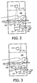
- FIGURES 2, 3 , 4 and 5 schematically illustrate a non-limiting example of the supplemental source 114 in connection with the system 100.
- FIGURES 2 and 3 schematically illustrate side views of the system 100 looking into the system 100 from the x-direction
- FIGURE 4 schematically illustrates a view looking into the examination region 106 from the z-direction
- FIGURE 5 schematically illustrates a view looking down from the source 110 into the detector array 116 from the y-direction.
- the supplemental source 114 is affixed to a moveable portion 204 of a bearing 206.
- a stationary portion 208 of the bearing 206 is affixed in the system 100.
- a drive mechanism 210 is configured to move the moveable portion 204 of the bearing 206 and hence the supplemental source 114.
- Suitable bearings include, but are not limited to, a linear slide, ball, roller, and/or other bearing.
- Suitable drive mechanisms include, but are not limited to, a belt, chain, lead screw, ball screw, two or more gears, etc., and a motor. Other approaches, including a combination of the above, are also contemplated herein.
- a controller 212 is configured to control the drive mechanism 208 to move the supplemental source 114 via the bearing 206, for example, between at least two positions, including a first or retracted position 214 ( FIGURE 2 ) in which the supplemental source 114 is not located in a region 216 between the subject support 108 and the detector array 116, and a second or extended position 302 ( FIGURE 3 ) in which the supplemental source 114 is located in the region 216 between the subject support 108 and the detector array 116.
- the supplemental source 114 is positioned in the retracted position 214 ( FIGURE 2 ) when scanning an object or subject and in the extended position 302 ( FIGURE 3 ) for performing a supplemental scan.
- the radiation source 114 is in the extended position 302 ( FIGURE 3 ) and activated to emit x-ray radiation. As shown in FIGURE 4 , the supplemental source 114 extends in the x-direction only over a sub-portion of the length of the inner detectors 116 3 . As shown in FIGURE 5 , the supplemental source 114 extends in the z-direction at least the entire z-axis width of the detector array 116.
- the detector array 116 rotates as the supplemental source 114 emits x-ray radiation, and the radiation emitted by the supplemental source 114 sequentially illuminates, column by column, all the detectors elements of the detector array 116, including the outer detector 116 1 , the inner detectors 116 3 , and the outer detectors 116 2 .
- the detector array 116 has the shape of a matrix of pixels 502 ( FIGURE 5 ) on the surface of an arc ( FIGURE 4 ).
- the detector array 116 has geometry of about ten (10) centimeters (cm) wide along the z-direction and about one hundred (100) cm along the arc or x-direction. In other embodiments, the detector array 116 is wider or narrower and/or longer or short.
- the geometry and pixel size of the outer detectors 116 1 and 116 2 and the inner detectors 116 3 are the same, and the location of the outer detectors 116 1 and 116 2 with respect to the inner detectors 116 3 is the same. In other embodiments, geometry and pixel size and/or the locations may be different.
- the supplemental source 114 is a line source with an array 404 of emitting regions spatially distributed along a longitudinal axis.
- the line source 114 is spatially oriented with respect to the detector array 116 such that the longitudinal axis of the line source is transverse to the longitudinal axis of the detector array 116.
- An example of a suitable line source includes, but is not limited to, a carbon nanotube (CNT) x-ray source. Carbon nanotubes generally are good electron field emitters due to their high aspect ratio, superior electrical and thermal conductivity, and relatively high chemical and mechanical stability.
- the x-ray tube current is generated by applying an external electrical field to extract the electrons from the CNTs.
- x-ray radiation with programmable waveforms can be readily generated and gated with physiological signals or others.
- Spatially distributed x-ray source arrays with one- and two-dimensionally distributed focal spots are constructed by using matrix addressable multi-pixel CNT cathode. Switching, scanning, and regulating the x-ray beams can be achieved through gate control electronics.
- Carbon nanotube cold cathodes are also relatively easy to make, either by chemical vapor deposition in situ growth or by post-growth transfer onto a substrate.
- a line-shaped x-ray source can be fabricated using field emission x-ray source technology.
- the cathode can be made by CNT technology or otherwise with an array of micromachined field emission tips. By doing so, it is possible to obtain very sharp tips and very close proximity between the tips and the gate electrode. This greatly reduces the potential difference between the tip and the gate required to achieve the field emission.
- the array 404 of emitting regions may be very densely packed. As a result, even though the current that can be obtained from a single tip is small, the total current that can be obtained from an array can be much larger.
- a line-shaped x-ray source can be fabricated. The width can be made as narrow as one hundredth (0.01) of a millimeter (mm) or less, and the length of the source can be made in tens of centimeters or longer.
- the array of emitters of the radiation source 114 may or may not produce a homogenous beam along the long axis (z-direction) of the radiation source 114.
- the line source has: 1) temporal stability over about one (1) second.; 2) spatial uniformity on a length of about one (1) mm; 3) an intensity or the power on the order of magnitude of micro Amperes of source current, while using an electron accelerating voltage in the order of 100 kV.
- Such low power is sufficient because the source is very close (e.g., few centimeters) to the detector array 110; 4) an x-ray spectrum in a range of the spectrum produced by standard x-ray tube operated in 80-140 kV (however, it is not required that the spectrum will be completely identical to the primary source 108).
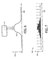
- FIGURE 6 shows a profile 602 of radiation intensity of the line source on a single detector element as a function of rotation angle of the detector array 116 with respect to the line source, wherein a y-axis 604 represents intensity and an x-axis 606 represents rotation angle.
- FIGURE 7 shows a profile 702 of the output signal of the detector element of FIGURE 6 as a function of integration period for the detector element, wherein a y-axis 704 represents signal level and an x-axis 706 represents integration period.
- the profiles 602 and 702 start from a low value, increase to a maximum, and then decrease to a low value.
- a maximum signal is estimated when the detector pixel passes beneath the source. This can be done for example by interpolation between the five highest readings.
- a second approach is to sum all readings which are above a pre-defined noise threshold.
- a third approach is to simply take the highest reading signal. Other approaches are also contemplated herein.
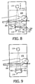
- FIGURE 8 schematically illustrates a variation in which the supplemental source 114 is in the path of the beam from the primary source 110 while the primary source 110 emits radiation.
- the supplemental source 114 is moved to the extended position 302 as described herein and left there while scanning the object or subject. This variation can be used for undersampled acquisitions where rays passing through the supplemental source 114 can be ignored or discarded.
- FIGURE 9 schematically illustrates another variation in which the supplemental source 114 is located at static position.
- the supplemental source 114 is stationarily affixed at the extended position 302 via brackets 902.
- this embodiment can be used for undersampled acquisitions where rays passing through the supplemental source 114 can be ignored or discarded.
- a suitable reconstruction technique is a reconstruction technique that can deal with undersampled projections such as a statistical iterative reconstruction technique, compressed sensing methods, and/or known image reconstruction technique.
- suitable reconstruction techniques can be found at least in US patent application publication 20090175523 ("Method for image reconstruction using sparsity-constrained correction"), US patent application publication 20090161933 ("Method for dynamic prior image constrained image reconstruction"), US patent application publication 20090161932 (“Method for prior image constrained image reconstruction”), and US patent application publication 20070010731 ("Highly constrained image reconstruction method”).
- the secondary radiation source 114 is not located in the stationary gantry 102 between the support 108 and detector array 106.
- the secondary radiation source 114 can alternatively be located in the subject support 108, affixed to the outside cover of the stationary gantry 102 within the aperture and over the region where x-rays emitted by the primary source 110 traverse to illuminate the detector array 116, and/or other regions.
- FIGURE 10 schematically illustrates example method of gain calibrating the detector array 116.
- the imaging examination includes a plurality of scans.
- an air scan is performed.
- the primary source 110 is used to perform air scans.
- a supplemental scan is performed.
- the supplemental source 114 is used to perform supplemental scans.
- air scan calibration data is generated for the air scan for both the inner detectors 116 3 (with the less stable detectors) and the outer detectors 116 1 and 116 2 .
- first calibration update data is generated for both the inner detectors 116 3 and the outer detectors 116 1 and 116 2 .
- an object or subject is positioned in the examination region 106 for a scan.
- the object or subject is scanned.
- the primary source 110 is used to perform object or subject scans.
- a supplemental scan is performed in connection with the object or subject scan.
- second calibration update data is generated for both the inner detectors 116 3 and the outer detectors 116 1 and 116 2 .
- the air scan calibration data is updated based on the first and second calibration update data.
- projection data from the scan of the object or subject is corrected based on the detector gain calibration data.
- the corrected projection data is reconstructed, generating volumetric image data of the object or subject.
- act 1012 can be performed before or concurrently with act 1010.
- acts 1008 to 1020 are repeated for each scan.
- a subsequent scan is performed with the object or subject at a different z-axis location, the object or subject can be moved before, during and/or after performing a supplemental scan.
- the above may be implemented via one or more processors executing one or more computer readable instructions encoded or embodied on computer readable storage medium such as physical memory which causes the one or more processors to carry out the various acts and/or other functions and/or acts. Additionally or alternatively, the one or more processors can execute instructions carried by transitory medium such as a signal or carrier wave.
- the following provides an example of generating air scan calibration data, calibration update data and detector gain calibration data (via the detector gain calibration data determiner 118), correcting projection data with the detector gain calibration data (via the detector gain corrector 128), and reconstructing the corrected projection data (via the reconstructor 130).
- I I 0 e ⁇ ⁇ ⁇ x dx
- I the radiation intensity of an x- ray incident on a single detector element after traversing the portion of an object or subject in the examination region 106
- I 0 the radiation intensity of the x-ray before traversing the the portion of an object or subject therein
- ⁇ ( x ) the local radiation attenuation of the x- ray in the object or subject.
- S 0 S 0 m ⁇ k
- S m 0 the signal from the air scan, which is performed using the primary source 110
- k is a ratio of the tube current of the object or subject scan to the tube current of the air scan.
- the air scan processor 120 processes the data from the air scan and stores S m 0 for each detector element in the memory 126.
- the x-ray tube current value that was used during the air calibration is also stored in the memory 126 and is used to calculate the ratio k automatically for each object or subject scan.
- a supplemental scan uses the supplemental source 114, measures S m c and S m r , where S m c is the signal of an unstable detector pixel (from inner detectors 116 3 ) and S m r is the signal of a stable detector pixel (from outer detectors 116 1 or 116 2 ), or a weighting of the two outer detectors 116 1 and 116 2 , in a same detector row.
- the supplemental scan processor 122 process the data from the supplemental scan and stores in these measurements the memory 126.
- another or subsequent supplemental scan(s) is performed (using the supplemental source 114) before, during, between and/or after an object or subject scan (using the primary source 110), measuring S n c and S r n .
- the supplemental scan processor 122 process the data from the subsequent supplemental scan and stores the corresponding measurements in the memory 126.
- S c n is corrected based on EQUATION 7:
- S c n ′ S c n ⁇ S r m S r n where S n ⁇ c is the corrected S c n with respect to any changes in the distributed line-source from the time of the previous supplemental scan.
- the detector gain calibration determiner 118 updates the detector gain calibration data stored in the memory 126 by replacing the previous values S m 0 (for each detector pixel) with the new values S m ⁇ 0 .
Description
- The following generally relates to calibrating radiation sensitive detectors of an x-ray based imaging system detector array and is described with particular application to computed tomography (CT); however, the following is also amenable to other x-ray based imaging systems.
- A CT scanner generally includes an x-ray tube supported by a rotating gantry, which is rotatably affixed to a stationary gantry. The x-ray tube emits radiation that traverses an examination region and a portion of an object or subject therein. A subject support positions the object or subject in the examination region for scanning. A radiation sensitive detector array is disposed across the examination region, opposite the x-ray tube, and includes a plurality of detector elements that detects radiation traversing the examination region and produces projection data indicative of the detected radiation. The projection data can be reconstructed to generate volumetric image data indicative of the portion of the object or subject in the examination region.
- A conventional CT scanner typically includes integrating detectors, which typically include a scintillator array optically coupled to a photodiode array (e.g., of silicon photodiodes). Conventional CT scintillator are based, for example, on Gd2O2S (referred to as GOS), (LuTb)3Al5O12 (referred to as LuTbAG) or several forms of (Gd, Y, Ga)AG. The scintillator array includes scintillating material that absorbs x-rays that pass through the examination region and the portion of the object or subject and produces light in proportion to the total energy of the absorbed x-rays. The photodiode array absorbs the light produced by the scintillating material and converts the absorbed light into an electrical current in proportion to the light absorbed. The ideal detector produces a signal current in direct proportion to the x-ray intensity (i.e. the total energy of all photons in a reading) absorbed in the detector.
- Such detectors have time dependent gains. Generally, the gain of a detector represents the transfer function from x-ray energy to an electric signal. Typically, the material selected for the scintillator of the detector array has a gain that is nearly constant over time. As such, an air calibration scan is performed to generate detector gain calibration data and subsequent air calibration scans can be made once every month or so to reflect changes in detector gain. Generally, an air calibration includes scanning with nothing located in the examination region so that the x-rays pass through the examination region without being attenuated and the gain of each detector is determined based on the output signal of the detectors. Any change in gain between calibrations typically may not be significant and has been neglected.
- In some instances, the above-noted conventional CT detectors may not be the optimal choice or even appropriate, for example, for applications such as those involving spectral CT, photon counting, or protocols using very low detected x-ray flux. For such applications, detectors with higher gain (light output) or with spectral resolved properties is often the better choice. Scintillators with higher light output may be better suited since they offer a higher signal to noise ratio and reduced image artifacts in cases such as: 1) clinical protocols with low patient dose; 2) high speed scans (e.g., cardiac scans); 3) protocols with low tube voltage for high soft tissue contrast definition; 4) CT scanners having detector arrays with especially small pixels for high spatial resolution; 5) double-layer dual-energy CT for better material separation, and/or other advantages. Direct conversion materials may be the optimal choice for photon-counting spectral CT.
- Several detector materials with higher light output (relative to GOS) are known. Examples of such materials include scintillator materials such as ZnSe (maximum (max.) ~80,000 photons/mega-electron volt (ph/MeV)), Y2O2S (max. ~63,000 ph/MeV), SrI2 (max. ~90,000 ph/MeV), LaBr3 (max. ~61,000 ph/MeV), Ba2CsI5 (max. ~97,000 ph/MeV), etc., and direct conversion materials such as CdZnTe, CdTe, TlBr, GaAs, etc. For comparison, the conventional GOS scintillator can reach lower light output of max. ~50,000 photons/MeV. Several light-element scintillators such as the aforementioned ZnSe may be well-suited for double-layer dual-energy CT detectors. From the aspect of light photodetectors, silicon photomultipliers (SiPM) or avalanche photodiodes (APD) can be used to achieve higher sensitivity.
- Unfortunately, the above noted materials have unstable that the gains change more frequently over time, relative to the gain of the aforementioned conventional scintillators. As such, conventional approaches for calibrating for gain with a conventional scintillator, such as the example approach discussed above in which the gain is recalibrated every month or so, are not well suited to be used to calibrate the gain of such materials. Therefore, there is an unresolved need for other approaches for calibrating detectors for gain.
-
US 7,873,144 B2 discloses a radiographic imaging apparatus comprising a primary radiation source which projects a beam of radiation into an examination region. A detector converts detected radiation passing through the examination region into electrical detector signals representative of the detected radiation. The detector has at least one temporally changing characteristic such as an offset B(t) or gain A(t). A grid pulse means turns the primary radiation source ON and OFF at a rate between 1000 and 5000 pulses per second, such that at least the offset B(t) is re-measured between 1000 and 5000 times per second and corrected a plurality of times during generation of the detector signals. The gain A(t) is measured by pulsing a second pulsed source of a constant intensity with a second pulse means. The gain A(t) is re-measured and corrected a plurality of times per second during generation of the detector signals. -
US 2011/0012014 A1 discloses a method that includes detecting radiation that traverses a material having a known spectral characteristic with a radiation sensitive detector pixel that outputs a signal indicative of the detected radiation and determining a mapping between the output signal and the spectral characteristic. The method further includes determining an energy of a photon detected by the radiation sensitive detector pixel based on a corresponding output of the radiation sensitive detector pixel and the mapping. -
US 2010/0051816 A1 discloses a method for providing information about a spatial gain distribution of a scintillator for a primary radiation which does not require the irradiation of the scintillator with the primary radiation. -
US 2008/0217541 A1 discloses a medical imaging system including a positron emission tomography (PET) imaging apparatus and a computed tomography (C'T) imaging apparatus. The CT imaging apparatus includes a rotatable gantry. A radioactive source loader is attached to the rotatable gantry to rotate therewith. The radioactive source loader further includes a radioactive source to calibrate the PET imaging apparatus. - Aspects of the present application address the above-referenced matters and others.
- According to one aspect, a CT imaging system includes a stationary gantry and a rotating gantry, wherein the rotating gantry is rotatably supported by the stationary gantry. The rotating gantry includes a primary source that is configured to emit primary radiation and a detector array having at least one row of detector elements extending along a longitudinal axis. The primary source and the detector array are located opposite each other, across an examination region, and the primary radiation traverses a path between the primary source and the detector array and through an examination region and illuminates the at least one row of detector elements of the detector array, which detects the primary radiation. The system further includes a supplemental source, wherein the supplemental source is affixed to a non-rotating portion of the CT imaging system and is configured to emit secondary radiation, which, when the detector array faces the supplemental source, traverses a sub-portion of the path and illuminates the at least one row of detector elements of the detector array, which detects the secondary radiation.
- The supplemental source may be configured to move between a first position in which the supplemental source is in the path between the primary source and the detector array and a second position in which the supplemental source is outside of the path between the primary source and the detector array, and the supplemental source may be actuated to emit radiation only when the supplemental source is in the second position.
- The radiation emitted by the supplemental source may be continuous, non-pulsed radiation.
- The CT imaging system may further comprise a detector gain calibration determiner that is configured to determine a detector gain calibration data for the detector array based on data acquired using the primary source during an air scan and data acquired using the supplemental source.
- The supplemental source may be actuated to emit radiation with an object or subject in the examination region.
- The supplemental source may be actuated to emit radiation concurrently while the primary source is used to perform an object or subject scan.
- In another aspect, a method of calibrating the CT imaging system includes performing an initial detector gain calibration procedure, which includes performing an air scan using the primary source, which is also used to perform object or subject scans, and performing a supplemental scan using the supplemental source, which is not used to perform the object or subject scans. The method further includes performing an object or subject scan, which includes scanning an object or subject using the primary source, and performing a subsequent supplemental scan using the supplemental source. The method further includes generating a signal in electronic format which is indicative of detector gain calibration data
- based on results of the initial detector gain calibration procedure and the subsequent supplemental scan.
- The subsequent supplemental scan may be performed with the object or subject in an examination region in which the object or subject scan is performed.
- The subsequent supplemental scan may be performed concurrently with the object or subject scan of the object or subject in the examination region.
- The supplemental source may be a line source with a plurality of emitting regions distributed along a long axis of the line source.
- The method may further comprise actuating the supplemental source to emit non-pulsed radiation to perform the subsequent supplemental scan.
- The method may further comprise actuating the supplemental source to emit radiation while re-positioning the object or subject for a subsequent scan.
- In another aspect, a method of calibrating the CT imaging system includes obtaining air scan calibration data, for the detector array, which is generated based on an air calibration scan performed using a primary source, which is also used to scan an object or subject. The method further includes obtaining first calibration update data, for the detector array, which is generated based on a supplemental scan performed with the supplemental source, which is not used to scan the object or subject. The air scan calibration data and the first calibration update data are part of a same initial detector gain calibration procedure. The method further includes obtaining second calibration update data, for the detector array, which is generated based on a subsequent supplemental scan performed with the supplemental source. The method further includes obtaining data acquired while scanning the object or subject using the primary source. The second calibration update data and the data acquired are part of a same object or subject scan procedure. The method further includes generating detector gain calibration data based on the obtained air scan calibration data, the obtained first calibration update data and the obtained second calibration update data. The method further includes correcting the data acquired based on the generated detector gain calibration data.
- Still further aspects of the present invention will be appreciated to those of ordinary skill in the art upon reading and understand the following detailed description.
- The invention may take form in various components and arrangements of components, and in various steps and arrangements of steps. The drawings are only for
purposes of illustrating the preferred embodiments and are not to be construed as limiting the invention. -
FIGURE 1 schematically illustrates an example imaging system with a primary source, a supplemental source, and a detector gain calibration data determiner, which determines detector gain calibration data based on data acquired using both the primary and the supplemental sources. -
FIGURES 2 and 3 schematically illustrate an example of the supplemental source looking into the system along the x-direction. -
FIGURE 4 schematically illustrates the example of the supplemental source looking into the system along the z-direction. -
FIGURE 5 schematically illustrates the example of the supplemental source looking into the system along the y-direction. -
FIGURE 6 illustrates an example profile of x-ray intensity on a detector element from the supplemental source as a function of the detector array rotation angle with respect to the supplemental source. -
FIGURE 7 illustrates an example profile of the signal output by the detector element ofFIGURE 6 as a function of integration period for the detector element. -
FIGURES 8 and 9 schematically illustrate non-limiting variations of supplemental source in the system. -
FIGURE 10 illustrates an example method for gain calibrating the detector array of the imaging system. -
FIGURE 1 illustrates animaging system 100 such as a computed tomography (CT) scanner. - The
imaging system 100 includes astationary gantry 102 and arotating gantry 104, which is rotatably supported by thestationary gantry 102. Therotating gantry 104 is configured to rotate around anexamination region 106 about a longitudinal or z-axis. - A
subject support 108, such as a couch, supports an object or subject (human or animal) in theexamination region 106 and positions the object or subject with respect to x, y, and/or z axes before, during and/or after scanning. - A
primary source 110, such as an x-ray tube, is supported by therotating gantry 104 and rotates in coordination with therotating gantry 104 about theexamination region 106. Theprimary source 110 emits a generally fan, cone, or wedged shaped radiation beam that traverses along apath 112 from one side of theexamination region 106 to the other. Theprimary source 110 is used to perform a conventional air scan or an object or subject scan. - A
supplemental source 114 is affixed in thestationary gantry 102. InFIGURE 1 , thesupplemental source 114 is located in a region that is below thesubject support 108. As such, when thesupplemental source 114 is actuated to emit radiation, thesupplemental source 114 emits radiation that traverses only a sub-portion of thepath 112. As described in greater detail below, thesupplemental source 114 can be employed before, during, between and/or after an object or subject scan(s) performed with theprimary radiation source 110 or after an air scan performed with theprimary source 110. - A radiation
sensitive detector array 116 is also supported by therotating gantry 104 and is located opposite theradiation source 110, across theexamination region 106 to the other side of theexamination region 106. Thedetector array 116 includes one or more rows of detector elements, where each row extends along the x-direction, and the rows (where there are two or more) are arranged with respect to each other along the z-direction. The detector elements detect radiation (from theprimary source 110 and/or the supplemental source 114) traversing the at least part of thepath 112 and generate projection data indicative thereof. - The
detector array 116 includesouter detectors inner detectors 1163, which are located between theouter detectors outer detectors inner detectors 1163 include a material and/or detector technology with higher gain and/or other improved characteristics relative to the conventional detectors with the stable gain. Suitable materials include scintillating materials such as ZnSe, Y2O2S, SrI2, LaBr3, Ba2CsI5, and/or other scintillating material, direct conversion materials such as CdZnTe, CdTe, TlBr, GaAs, and/or other direct conversion material, and suitable technologies include silicon photomultipliers (SiPM), avalanche photodiodes (APD), and/or other detector technologies. Such materials and/or technologies tend to have unstable gains relative to conventional detectors, in that gain changes that impact image quality occur more frequently with respect to time relative to conventional detector. - A detector
gain calibration determiner 118 determines detector gain calibration data for each object or subject scan. The illustrated detectorgain calibration determiner 118 includes anair scan processor 120 that receives data acquired during a conventional air scan performed with theprimary source 110 without an object or subject in theexamination region 106 and generates air scan calibration data therewith. Any known or other approach can be used to generate the air scan calibration data. - The detector
gain calibration determiner 118 also includes asupplemental scan processor 122 that receives data acquired during a supplemental scan performed with thesupplemental source 114 with or without an object or subject in theexamination region 106 and generates calibration update data. The supplemental scans can be performed for each object or subject scan, including each object or subject scan of an image procedure that includes a series of object or subject scans. - The detector
gain calibration determiner 118 also includes acalibration data updater 124 that updates the air scan calibration data for a particular object or subject scan based on the calibration update data generated from a supplemental scan for the particular object or subject scan and calibration update data from a previous supplemental scan, producing the detector gain calibration data. In one instance, the calibration update data serves as a second-order correction in addition to air scan calibration data (e.g., a small correction relative to the primary correction). An example approach for generating the update data and producing the detector gain calibration data is discussed in greater detail below. -
Memory 126 is used to store one or more of the detector gain calibration data, the calibration update data, and the air scan calibration data. The detectorgain calibration determiner 118 can read from and write to thememory 126. - A
detector gain corrector 128 corrects signals generated by the detector array 116 (or a detector array of another system) based on the detector gain calibration data in thememory 126. Any known or other approach can be used to correct the projection data based on the detector calibration data. An example approach for correcting the project data is discussed in greater detail below. - A
reconstructor 130 reconstructs the corrected projection data and generates volumetric image data indicative of theexamination region 106 and a portion of the object or subject therein. An example approach for reconstructing the corrected projection data is discussed in greater detail below. The reconstructed image data can be further processed to generate one or more images of the portion of the object or subject which can be filmed, visually presented, saved, and/or otherwise processed. - A general purpose computing system serves as an
operator console 132, and includes an output device such as a display and an input device such as a keyboard, mouse, and/or the like. In the illustrated embodiment, theconsole 132 is configured to control thesystem 100, for example, to perform an air calibration scan (with the primary source 110), a supplemental scan (with the supplemental source 114) and/or an object or subject scan (with the primary source 110), actuate the detectorgain calibration determiner 118, actuate thedetector gain corrector 128, and/or otherwise control thesystem 100. - It is to be appreciated that the detector
gain calibration determiner 118 and/or thedetector gain corrector 128 can be implemented via one or more processor executing one or more computer executable instructions embedded on computer readable storage medium such as physical memory. Additionally or alternatively, at least one of the computer executable instructions is carried by a signal or carrier wave. Moreover, the detectorgain calibration determiner 118 and/or thedetector gain corrector 128 can be local or remote to thesystem 100 and/or part of theconsole 132 and/or one or more other computing device. -
FIGURES 2, 3 ,4 and 5 schematically illustrate a non-limiting example of thesupplemental source 114 in connection with thesystem 100.FIGURES 2 and 3 schematically illustrate side views of thesystem 100 looking into thesystem 100 from the x-direction,FIGURE 4 schematically illustrates a view looking into theexamination region 106 from the z-direction, andFIGURE 5 schematically illustrates a view looking down from thesource 110 into thedetector array 116 from the y-direction. - Initially referring to
FIGURES 2 and 3 , thesupplemental source 114 is affixed to amoveable portion 204 of abearing 206. Astationary portion 208 of thebearing 206 is affixed in thesystem 100. Adrive mechanism 210 is configured to move themoveable portion 204 of thebearing 206 and hence thesupplemental source 114. Suitable bearings include, but are not limited to, a linear slide, ball, roller, and/or other bearing. Suitable drive mechanisms include, but are not limited to, a belt, chain, lead screw, ball screw, two or more gears, etc., and a motor. Other approaches, including a combination of the above, are also contemplated herein. - A
controller 212 is configured to control thedrive mechanism 208 to move thesupplemental source 114 via thebearing 206, for example, between at least two positions, including a first or retracted position 214 (FIGURE 2 ) in which thesupplemental source 114 is not located in aregion 216 between thesubject support 108 and thedetector array 116, and a second or extended position 302 (FIGURE 3 ) in which thesupplemental source 114 is located in theregion 216 between thesubject support 108 and thedetector array 116. In this example, thesupplemental source 114 is positioned in the retracted position 214 (FIGURE 2 ) when scanning an object or subject and in the extended position 302 (FIGURE 3 ) for performing a supplemental scan. - In
FIGURES 4 and 5 , theradiation source 114 is in the extended position 302 (FIGURE 3 ) and activated to emit x-ray radiation. As shown inFIGURE 4 , thesupplemental source 114 extends in the x-direction only over a sub-portion of the length of theinner detectors 1163. As shown inFIGURE 5 , thesupplemental source 114 extends in the z-direction at least the entire z-axis width of thedetector array 116. Thedetector array 116 rotates as thesupplemental source 114 emits x-ray radiation, and the radiation emitted by thesupplemental source 114 sequentially illuminates, column by column, all the detectors elements of thedetector array 116, including theouter detector 1161, theinner detectors 1163, and theouter detectors 1162. - In
FIGURES 4 and 5 , thedetector array 116 has the shape of a matrix of pixels 502 (FIGURE 5 ) on the surface of an arc (FIGURE 4 ). Thedetector array 116 has geometry of about ten (10) centimeters (cm) wide along the z-direction and about one hundred (100) cm along the arc or x-direction. In other embodiments, thedetector array 116 is wider or narrower and/or longer or short. The geometry and pixel size of theouter detectors inner detectors 1163 are the same, and the location of theouter detectors inner detectors 1163 is the same. In other embodiments, geometry and pixel size and/or the locations may be different. - In
FIGURES 4 and 5 , thesupplemental source 114 is a line source with anarray 404 of emitting regions spatially distributed along a longitudinal axis. Theline source 114 is spatially oriented with respect to thedetector array 116 such that the longitudinal axis of the line source is transverse to the longitudinal axis of thedetector array 116. An example of a suitable line source includes, but is not limited to, a carbon nanotube (CNT) x-ray source. Carbon nanotubes generally are good electron field emitters due to their high aspect ratio, superior electrical and thermal conductivity, and relatively high chemical and mechanical stability. - With CNTs, the x-ray tube current is generated by applying an external electrical field to extract the electrons from the CNTs. By varying the extraction electrical field, x-ray radiation with programmable waveforms can be readily generated and gated with physiological signals or others. Spatially distributed x-ray source arrays with one- and two-dimensionally distributed focal spots are constructed by using matrix addressable multi-pixel CNT cathode. Switching, scanning, and regulating the x-ray beams can be achieved through gate control electronics.
- Carbon nanotube cold cathodes are also relatively easy to make, either by chemical vapor deposition in situ growth or by post-growth transfer onto a substrate. A line-shaped x-ray source can be fabricated using field emission x-ray source technology. The cathode can be made by CNT technology or otherwise with an array of micromachined field emission tips. By doing so, it is possible to obtain very sharp tips and very close proximity between the tips and the gate electrode. This greatly reduces the potential difference between the tip and the gate required to achieve the field emission.
- The
array 404 of emitting regions may be very densely packed. As a result, even though the current that can be obtained from a single tip is small, the total current that can be obtained from an array can be much larger. Using the technique as described above, a line-shaped x-ray source can be fabricated. The width can be made as narrow as one hundredth (0.01) of a millimeter (mm) or less, and the length of the source can be made in tens of centimeters or longer. The array of emitters of theradiation source 114 may or may not produce a homogenous beam along the long axis (z-direction) of theradiation source 114. - In one non-limiting instance, the line source has: 1) temporal stability over about one (1) second.; 2) spatial uniformity on a length of about one (1) mm; 3) an intensity or the power on the order of magnitude of micro Amperes of source current, while using an electron accelerating voltage in the order of 100 kV. Such low power is sufficient because the source is very close (e.g., few centimeters) to the
detector array 110; 4) an x-ray spectrum in a range of the spectrum produced by standard x-ray tube operated in 80-140 kV (however, it is not required that the spectrum will be completely identical to the primary source 108). -
FIGURE 6 shows aprofile 602 of radiation intensity of the line source on a single detector element as a function of rotation angle of thedetector array 116 with respect to the line source, wherein a y-axis 604 represents intensity and anx-axis 606 represents rotation angle.FIGURE 7 shows aprofile 702 of the output signal of the detector element ofFIGURE 6 as a function of integration period for the detector element, wherein a y-axis 704 represents signal level and anx-axis 706 represents integration period. - As shown in
FIGURES 6 and 7 , theprofiles - Variations are contemplated.
-
FIGURE 8 schematically illustrates a variation in which thesupplemental source 114 is in the path of the beam from theprimary source 110 while theprimary source 110 emits radiation. InFIGURE 8 , thesupplemental source 114 is moved to theextended position 302 as described herein and left there while scanning the object or subject. This variation can be used for undersampled acquisitions where rays passing through thesupplemental source 114 can be ignored or discarded. -
FIGURE 9 schematically illustrates another variation in which thesupplemental source 114 is located at static position. InFIGURE 9 , thesupplemental source 114 is stationarily affixed at theextended position 302 viabrackets 902. Likewise, this embodiment can be used for undersampled acquisitions where rays passing through thesupplemental source 114 can be ignored or discarded. - In the variations illustrated in
figures 8 and 9 , an appropriate image reconstruction technique is used. A suitable reconstruction technique is a reconstruction technique that can deal with undersampled projections such as a statistical iterative reconstruction technique, compressed sensing methods, and/or known image reconstruction technique. Examples of suitable reconstruction techniques can be found at least inUS patent application publication 20090175523 ("Method for image reconstruction using sparsity-constrained correction"),US patent application publication 20090161933 ("Method for dynamic prior image constrained image reconstruction"),US patent application publication 20090161932 ("Method for prior image constrained image reconstruction"), andUS patent application publication 20070010731 ("Highly constrained image reconstruction method"). - In another variation, the
secondary radiation source 114 is not located in thestationary gantry 102 between thesupport 108 anddetector array 106. For example, thesecondary radiation source 114 can alternatively be located in thesubject support 108, affixed to the outside cover of thestationary gantry 102 within the aperture and over the region where x-rays emitted by theprimary source 110 traverse to illuminate thedetector array 116, and/or other regions. -
FIGURE 10 schematically illustrates example method of gain calibrating thedetector array 116. For this example, the imaging examination includes a plurality of scans. - It is to be appreciated that the ordering of the below acts is for explanatory purposes and not limiting. As such, other orderings are also contemplated herein. In addition, one or more of the acts may be omitted and/or one or more other acts may be included.
- At 1000, an air scan is performed. As described herein, the
primary source 110 is used to perform air scans. - At 1002, a supplemental scan is performed. As described herein, the
supplemental source 114 is used to perform supplemental scans. - It is to be appreciated that the combination of
acts - At 1004, air scan calibration data is generated for the air scan for both the inner detectors 1163 (with the less stable detectors) and the
outer detectors - At 1006, first calibration update data is generated for both the
inner detectors 1163 and theouter detectors - At 1008, an object or subject is positioned in the
examination region 106 for a scan. - At 1010, the object or subject is scanned. As described herein, the
primary source 110 is used to perform object or subject scans. - At 1012, a supplemental scan is performed in connection with the object or subject scan.
- It is to be appreciated that the combination of
acts - At 1014, second calibration update data is generated for both the
inner detectors 1163 and theouter detectors - At 1016, the air scan calibration data is updated based on the first and second calibration update data.
- At 1018, projection data from the scan of the object or subject is corrected based on the detector gain calibration data.
- At 1020, the corrected projection data is reconstructed, generating volumetric image data of the object or subject.
- Additionally or alternatively,
act 1012 can be performed before or concurrently withact 1010. - Where the imaging exam includes more than one scan, acts 1008 to 1020 are repeated for each scan. Where a subsequent scan is performed with the object or subject at a different z-axis location, the object or subject can be moved before, during and/or after performing a supplemental scan.
- The above may be implemented via one or more processors executing one or more computer readable instructions encoded or embodied on computer readable storage medium such as physical memory which causes the one or more processors to carry out the various acts and/or other functions and/or acts. Additionally or alternatively, the one or more processors can execute instructions carried by transitory medium such as a signal or carrier wave.
- The following provides an example of generating air scan calibration data, calibration update data and detector gain calibration data (via the detector gain calibration data determiner 118), correcting projection data with the detector gain calibration data (via the detector gain corrector 128), and reconstructing the corrected projection data (via the reconstructor 130).
- Generally, the behavior of attenuated radiation in a scanned object or subject can be characterized as shown in EQUATION 1:

examination region 106, I0 is the radiation intensity of the x-ray before traversing the the portion of an object or subject therein, and µ(x) is the local radiation attenuation of the x- ray in the object or subject. - Signals S and S0 are assumed to be proportional to the radiation intensities I and I0 by a constant gain factor G, as shown in EQUATIONS 2 and 3:


- Based on EQUATIONS 1-3, if the detector gain is constant, the attenuation line integral P can be determined based on EQUATION 4:


- The relation between the signals of a particular scan to the data from the air scan is given by EQUATION 6:


primary source 110, and k is a ratio of the tube current of the object or subject scan to the tube current of the air scan. - The
air scan processor 120 processes the data from the air scan and stores
memory 126. The x-ray tube current value that was used during the air calibration is also stored in thememory 126 and is used to calculate the ratio k automatically for each object or subject scan. - A supplemental scan, using the
supplemental source 114, measures


outer detectors 1161 or 1162), or a weighting of the twoouter detectors supplemental scan processor 122 process the data from the supplemental scan and stores in these measurements thememory 126. - As part of an imaging examination of an object or subject, another or subsequent supplemental scan(s) is performed (using the supplemental source 114) before, during, between and/or after an object or subject scan (using the primary source 110), measuring


supplemental scan processor 122 process the data from the subsequent supplemental scan and stores the corresponding measurements in thememory 126. - From the stored measurements,


- The
calibration data updater 124 corrects the air scan calibration data based on EQUATION 8:
- The detector
gain calibration determiner 118 updates the detector gain calibration data stored in thememory 126 by replacing the previous values

- The
detector gain corrector 128 corrects a signal of an object or subject scan through: EQUATION 9:
- The
reconstructor 130 can determined the line integral for the corrected signal based on EQUATION 10:


- It is to be appreciated that that the foregoing provides a practical solution for calibrating unstable detectors, for example, during advanced clinical protocols in which the patient stays on the scanner table for a relatively long time such as in cases of multiple scans for perfusion studies or for interventional procedures. It may also enable repeated calibration between patients when a technician or other staff members are inside the CT room and there is a concern that the technician or other staff members will be exposed to ionizing radiation if the primary x-ray tube is operated during a standard air calibration procedure.
- The invention has been described herein with reference to the various embodiments. Modifications and alterations may occur to others upon reading the description herein. It is intended that the invention be construed as including all such modifications and alterations insofar as they come within the scope of the appended claims or the equivalents thereof.
Claims (15)
- A CT imaging system (100), comprising:a stationary gantry (102);a rotating gantry (104), wherein the rotating gantry is rotatably supported by the stationary gantry, the rotating gantry (104), including:wherein the primary source and the detector array are located opposite each other, across an examination region, such that the primary radiation traverses a path (112) between the primary source and the detector array and through the examination region (106) and illuminates the at least one row of detector elements of the detector array, which is configured to detect the primary radiation;a primary source (110) that is configured to emit primary radiation; anda detector array (116) having at least one row of detector elements (502) extending along a longitudinal axis,
characterized bya supplemental source (114), wherein the supplemental source is affixed to a non-rotating portion of the CT imaging system and is configured to emit secondary radiation, such that, when the detector array faces the supplemental source, the secondary radiation traverses a sub-portion of the path and illuminates the at least one row of detector elements of the detector array, which is configured to detect the secondary radiation. - The CT imaging system of claim 1, wherein the supplemental source is a line source with an array (404) of radiation emitting regions spatially distributed along a longitudinal axis of the line source.
- The CT imaging system of claim 2, wherein the line source is spatially oriented with respect to the detector array such that the long axis of the line source is transverse to the longitudinal axis of the detector array.
- The CT imaging system of any of claims 2 to 3, wherein the line source is configured to sequentially illuminate the detector elements as the detector array rotates through a path passing the supplemental source.
- The CT imaging system of any of claims 1 to 4, further comprising:a subject support (108) configured to position structure to be scanned in the examination region for scanning, wherein the supplemental source is located between the subject support and the detector array.
- The CT imaging system of any of claims 1 to 5, the detector array, comprising:first and second outer detectors (1161, 1162) having first gain; andinner detectors (1163) having second gain and located between the first and second outer detectors, wherein the first gain is more stable with respect to time than the second gain.
- The CT imaging system of any of claims 1 to 6, further comprising:a detector gain calibration determiner (118) that is configured to determine a detector gain calibration data for the detector array based on data acquired using the primary source during an air scan and data acquired using the supplemental source.
- The CT imaging system of claim 7, the detector gain calibration data determiner, comprising:an air scan processor (120) that is configured to generate air scan calibration data based on the data acquired using the primary source;a supplemental scan processor (122) that is configured to generate first calibration update data based on first data acquired using the supplemental source in connection with the air scan and second calibration update data based on second data acquired using the supplemental source in connection with an object or subject scan; anda calibration data updater (124) that is configured to update the air scan calibration data based on the first and second calibration update data, generating detector gain calibration data.
- The CT imaging system of claim 8, wherein the first and second calibration update data update the air scan calibration data to take into account gain changes in the detector array.
- The CT imaging system of any of claims 8 to 9, further comprising:a detector gain corrector (128) that is configured to correct projection data acquired during the object or subject scan with the generating detector gain calibration data, producing corrected projection data; anda reconstructor (130) that is configured to reconstruct the corrected projection data, producing volumetric image data.
- A method of calibrating the CT imaging system (100) of any of claims 1 to 10, comprising:performing an initial detector gain calibration procedure, which includes performing an air scan using the primary source (100), which is also used to perform object or subject scans, and performing a supplemental scan using the supplemental source, which is not used to perform the object or subject scans;performing an object or subject scan, which includes scanning an object or subject using the primary source, and performing a subsequent supplemental scan using the supplemental source; andgenerating a signal in electronic format which is indicative of detector gain calibration data based on results of the initial detector gain calibration procedure and the subsequent supplemental scan.
- The method of claim 11, further comprising:generating air scan calibration data based on the air scan;generating calibration update data based on the supplemental scan and the subsequent supplemental scan; andgenerating the signal based on the air scan calibration data and the calibration update data.
- The method of any of claims 11 to 12, further comprising:correcting projection data acquired via the object or subject scan, thereby producing corrected projection data; andreconstructing the corrected projection data, thereby generating volumetric image data indicative of the object or subject.
- The method of any of claims 11 to 13, further comprising:moving the supplemental source to a scanning position to perform the subsequent supplemental scan; andmoving the supplemental source to a non-scanning position to perform the object or subject scan using the primary source.
- A method of calibrating the CT imaging system (100) of any of claims 1 to 10, comprising:obtaining air scan calibration data, for the detector array (116), which is generated based on an air calibration scan performed using the primary source (110), which is also used to scan an object or subject;obtaining first calibration update data, for the detector array, which is generated based on a supplemental scan performed with the supplemental source (114), which is not used to scan the object or subject;wherein the air scan calibration data and the first calibration update data are part of a same initial detector gain calibration procedure;obtaining second calibration update data, for the detector array, which is generated based on a subsequent supplemental scan performed with the supplemental source;obtaining data acquired while scanning the object or subject using the primary source;wherein the second calibration update data and the data acquired are part of a same object or subject scan procedure;generating detector gain calibration data based on the obtained air scan calibration data, the obtained first calibration update data and the obtained second calibration update data; andcorrecting the data acquired based on the generated detector gain calibration data.
Applications Claiming Priority (2)
| Application Number | Priority Date | Filing Date | Title |
|---|---|---|---|
| US201161506816P | 2011-07-12 | 2011-07-12 | |
| PCT/IB2012/053565 WO2013008198A2 (en) | 2011-07-12 | 2012-07-12 | Imaging system detector calibration |
Publications (2)
| Publication Number | Publication Date |
|---|---|
| EP2731504A2 EP2731504A2 (en) | 2014-05-21 |
| EP2731504B1 true EP2731504B1 (en) | 2016-04-27 |
Family
ID=46851539
Family Applications (1)
| Application Number | Title | Priority Date | Filing Date |
|---|---|---|---|
| EP12759198.0A Active EP2731504B1 (en) | 2011-07-12 | 2012-07-12 | Imaging system detector calibration |
Country Status (5)
| Country | Link |
|---|---|
| US (1) | US9268046B2 (en) |
| EP (1) | EP2731504B1 (en) |
| JP (1) | JP6114745B2 (en) |
| CN (1) | CN103648391B (en) |
| WO (1) | WO2013008198A2 (en) |
Families Citing this family (15)
| Publication number | Priority date | Publication date | Assignee | Title |
|---|---|---|---|---|
| WO2014153561A1 (en) * | 2013-03-22 | 2014-09-25 | New York University | Computer accessible medium for modulating x-ray beam intensity |
| JP2014210047A (en) * | 2013-04-18 | 2014-11-13 | 株式会社東芝 | X-ray ct apparatus |
| US9903964B2 (en) * | 2014-05-02 | 2018-02-27 | Koninklike Philips N.V. | Method to calibrate a photon detector, absorption filter assembly and imaging apparatus |
| CN103951223B (en) * | 2014-05-08 | 2016-05-04 | 宁波大学 | Rare earth ion doped Ba2CsI5Devitrified glass and preparation method thereof |
| US10398404B2 (en) * | 2014-10-22 | 2019-09-03 | Hitachi, Ltd. | Data processing device, X-ray CT apparatus, and reference correction method |
| JP6464269B2 (en) * | 2014-12-15 | 2019-02-06 | コーニンクレッカ フィリップス エヌ ヴェKoninklijke Philips N.V. | PET system, dead time correction factor calculation method |
| DE102015202999B4 (en) * | 2015-02-19 | 2019-12-05 | Siemens Healthcare Gmbh | Automated adjustment of signal analysis parameters for X-ray detectors |
| US10725188B2 (en) * | 2015-10-20 | 2020-07-28 | Koninklijke Philips N.V. | Polarization correction for direct conversion x-ray detectors |
| US10226221B2 (en) * | 2016-08-30 | 2019-03-12 | Toshiba Medical Systems Corporation | Medical image processing method and apparatus |
| JP6890943B2 (en) * | 2016-10-06 | 2021-06-18 | キヤノンメディカルシステムズ株式会社 | Radiation diagnostic equipment and method |
| EP3533027B1 (en) * | 2016-10-28 | 2021-04-14 | Koninklijke Philips N.V. | Automatic ct detection and visualization of active bleeding and blood extravasation |
| CN107015267B (en) * | 2017-06-09 | 2018-10-09 | 河北格物仪器设备有限公司 | Detector gain corrects system and method |
| WO2019026129A1 (en) * | 2017-07-31 | 2019-02-07 | 株式会社島津製作所 | Radiation detector and nuclear medicine diagnosis device |
| US10898159B2 (en) * | 2019-01-11 | 2021-01-26 | General Electric Company | X-ray imaging system use and calibration |
| US11547378B2 (en) | 2019-07-11 | 2023-01-10 | Canon Medical Systems Corporation | Apparatus and method combining deep learning (DL) with an X-ray computed tomography (CT) scanner having a multi-resolution detector |
Family Cites Families (18)
| Publication number | Priority date | Publication date | Assignee | Title |
|---|---|---|---|---|
| JPS5365683A (en) * | 1976-11-25 | 1978-06-12 | Toshiba Corp | Inspector for radioactive rays |
| US4472823A (en) | 1982-03-17 | 1984-09-18 | U.S. Philips Corporation | Computed tomography apparatus with detector sensitivity correction |
| JPH0938075A (en) * | 1995-07-27 | 1997-02-10 | Shimadzu Corp | Radial rays exposure device |
| US5828719A (en) * | 1996-12-23 | 1998-10-27 | General Electric Company | Methods and apparatus for modulating data acquisition system gain |
| US6064068A (en) | 1997-06-11 | 2000-05-16 | Institute Of Geological & Nuclear Sciences Ltd. | System and method for monitoring the stability of a scintillation detector |
| US6075835A (en) * | 1998-08-25 | 2000-06-13 | General Electric Company | Methods and apparatus for imaging system quality readiness check |
| DE60132826T2 (en) * | 2001-10-01 | 2009-02-05 | Koninklijke Philips Electronics N.V. | METHOD AND DEVICE FOR CALIBRATING X-RAY EFFECTORS IN A COMPUTER TOMOGRAPHIC PICTURE SYSTEM |
| US7224763B2 (en) * | 2004-07-27 | 2007-05-29 | Analogic Corporation | Method of and system for X-ray spectral correction in multi-energy computed tomography |
| JP2008523872A (en) * | 2004-12-17 | 2008-07-10 | コーニンクレッカ フィリップス エレクトロニクス エヌ ヴィ | Pulsed X-ray for continuous detector correction |
| US7602951B2 (en) * | 2005-03-14 | 2009-10-13 | General Electric Company | Method and system for providing defective cell correction in a medical imaging device |
| DE602006010388D1 (en) | 2005-07-08 | 2009-12-24 | Wisconsin Alumni Res Found | Image reconstruction under constraints |
| JP2007178364A (en) | 2005-12-28 | 2007-07-12 | Hitachi Ltd | Nuclear medicine diagnostic equipment |
| US7755057B2 (en) * | 2007-03-07 | 2010-07-13 | General Electric Company | CT gantry mounted radioactive source loader for PET calibration |
| JP5714894B2 (en) * | 2007-04-12 | 2015-05-07 | コーニンクレッカ フィリップス エヌ ヴェ | Image detection device, imaging method, and computer program used therefor |
| JP5220125B2 (en) | 2007-12-20 | 2013-06-26 | ウイスコンシン アラムナイ リサーチ ファウンデーシヨン | A priori image-restricted image reconstruction method |
| EP2232444B1 (en) | 2007-12-20 | 2011-10-12 | Wisconsin Alumni Research Foundation | Method for dynamic prior image constrained image reconstruction |
| EP2596751B1 (en) * | 2008-04-01 | 2019-02-20 | Koninklijke Philips N.V. | Spectral detector calibration |
| US8958524B2 (en) * | 2013-01-31 | 2015-02-17 | Analogic Corporation | Correction of projection data in radiation system |
-
2012
- 2012-07-12 CN CN201280034114.7A patent/CN103648391B/en active Active
- 2012-07-12 WO PCT/IB2012/053565 patent/WO2013008198A2/en active Application Filing
- 2012-07-12 EP EP12759198.0A patent/EP2731504B1/en active Active
- 2012-07-12 JP JP2014519679A patent/JP6114745B2/en active Active
- 2012-07-12 US US14/129,720 patent/US9268046B2/en active Active
Also Published As
| Publication number | Publication date |
|---|---|
| CN103648391B (en) | 2016-08-17 |
| EP2731504A2 (en) | 2014-05-21 |
| WO2013008198A2 (en) | 2013-01-17 |
| WO2013008198A3 (en) | 2013-03-28 |
| CN103648391A (en) | 2014-03-19 |
| US9268046B2 (en) | 2016-02-23 |
| JP6114745B2 (en) | 2017-04-12 |
| US20140140469A1 (en) | 2014-05-22 |
| JP2014518147A (en) | 2014-07-28 |
Similar Documents
| Publication | Publication Date | Title |
|---|---|---|
| EP2731504B1 (en) | Imaging system detector calibration | |
| US8422636B2 (en) | Photon counting and energy discriminating detector threshold calibration | |
| US10898159B2 (en) | X-ray imaging system use and calibration | |
| US7873144B2 (en) | Pulsed x-ray for continuous detector correction | |
| JP5268499B2 (en) | Computerized tomography (CT) imaging system | |
| US7826587B1 (en) | System and method of fast kVp switching for dual energy CT | |
| US9579075B2 (en) | Detector array comprising energy integrating and photon counting cells | |
| US6399951B1 (en) | Simultaneous CT and SPECT tomography using CZT detectors | |
| US7260171B1 (en) | Apparatus for acquisition of CT data with penumbra attenuation calibration | |
| JP5367574B2 (en) | X-ray CT apparatus and method | |
| US7396162B1 (en) | Scatter correction for CT method and apparatus | |
| US20100282972A1 (en) | Indirect radiation detector | |
| JP5339562B2 (en) | Imaging method and system of nuclear medicine imaging apparatus, nuclear medicine imaging system and radiotherapy control system | |
| JP2009502227A (en) | X-ray detector imaging with multicolor spectrum | |
| JP2008104878A (en) | Distinct incident energy spectra detection | |
| JP2016131887A (en) | X-ray ct apparatus and image processing apparatus | |
| US20100189211A1 (en) | X-ray souce for measuring radiation | |
| US10070840B2 (en) | X-ray computed tomography apparatus and radiation medical imaging diagnostic apparatus | |
| JP2020030097A (en) | Sensitivity correction method and photon counting type detector | |
| JP2022111990A (en) | Photon counting type x-ray ct apparatus and method | |
| EP3466219B1 (en) | Apparatus for generating x-rays | |
| JP2024048207A (en) | X-ray CT scanner | |
| CN115460985A (en) | Cone beam computed tomography with continuous KV beam acquisition | |
| IL225473A (en) | Photon counting and energy discriminating detector threshold calibration |
Legal Events
| Date | Code | Title | Description |
|---|---|---|---|
| PUAI | Public reference made under article 153(3) epc to a published international application that has entered the european phase |
Free format text: ORIGINAL CODE: 0009012 |
|
| 17P | Request for examination filed |
Effective date: 20140212 |
|
| AK | Designated contracting states |
Kind code of ref document: A2 Designated state(s): AL AT BE BG CH CY CZ DE DK EE ES FI FR GB GR HR HU IE IS IT LI LT LU LV MC MK MT NL NO PL PT RO RS SE SI SK SM TR |
|
| DAX | Request for extension of the european patent (deleted) | ||
| REG | Reference to a national code |
Ref country code: DE Ref legal event code: R079 Ref document number: 602012017767 Country of ref document: DE Free format text: PREVIOUS MAIN CLASS: A61B0006030000 Ipc: A61B0006000000 |
|
| RIC1 | Information provided on ipc code assigned before grant |
Ipc: A61B 6/03 20060101ALI20150909BHEP Ipc: A61B 6/00 20060101AFI20150909BHEP Ipc: G01N 23/04 20060101ALI20150909BHEP Ipc: G01T 7/00 20060101ALI20150909BHEP Ipc: G01T 1/24 20060101ALI20150909BHEP |
|
| GRAP | Despatch of communication of intention to grant a patent |
Free format text: ORIGINAL CODE: EPIDOSNIGR1 |
|
| INTG | Intention to grant announced |
Effective date: 20151105 |
|
| GRAS | Grant fee paid |
Free format text: ORIGINAL CODE: EPIDOSNIGR3 |
|
| GRAA | (expected) grant |
Free format text: ORIGINAL CODE: 0009210 |
|
| AK | Designated contracting states |
Kind code of ref document: B1 Designated state(s): AL AT BE BG CH CY CZ DE DK EE ES FI FR GB GR HR HU IE IS IT LI LT LU LV MC MK MT NL NO PL PT RO RS SE SI SK SM TR |
|
| REG | Reference to a national code |
Ref country code: GB Ref legal event code: FG4D |
|
| REG | Reference to a national code |
Ref country code: CH Ref legal event code: EP |
|
| REG | Reference to a national code |
Ref country code: AT Ref legal event code: REF Ref document number: 793833 Country of ref document: AT Kind code of ref document: T Effective date: 20160515 |
|
| REG | Reference to a national code |
Ref country code: IE Ref legal event code: FG4D |
|
| REG | Reference to a national code |
Ref country code: DE Ref legal event code: R096 Ref document number: 602012017767 Country of ref document: DE |
|
| REG | Reference to a national code |
Ref country code: LT Ref legal event code: MG4D |
|
| REG | Reference to a national code |
Ref country code: NL Ref legal event code: MP Effective date: 20160427 |
|
| REG | Reference to a national code |
Ref country code: AT Ref legal event code: MK05 Ref document number: 793833 Country of ref document: AT Kind code of ref document: T Effective date: 20160427 |
|
| PG25 | Lapsed in a contracting state [announced via postgrant information from national office to epo] |
Ref country code: NL Free format text: LAPSE BECAUSE OF FAILURE TO SUBMIT A TRANSLATION OF THE DESCRIPTION OR TO PAY THE FEE WITHIN THE PRESCRIBED TIME-LIMIT Effective date: 20160427 |
|
| PG25 | Lapsed in a contracting state [announced via postgrant information from national office to epo] |
Ref country code: LT Free format text: LAPSE BECAUSE OF FAILURE TO SUBMIT A TRANSLATION OF THE DESCRIPTION OR TO PAY THE FEE WITHIN THE PRESCRIBED TIME-LIMIT Effective date: 20160427 Ref country code: FI Free format text: LAPSE BECAUSE OF FAILURE TO SUBMIT A TRANSLATION OF THE DESCRIPTION OR TO PAY THE FEE WITHIN THE PRESCRIBED TIME-LIMIT Effective date: 20160427 Ref country code: PL Free format text: LAPSE BECAUSE OF FAILURE TO SUBMIT A TRANSLATION OF THE DESCRIPTION OR TO PAY THE FEE WITHIN THE PRESCRIBED TIME-LIMIT Effective date: 20160427 Ref country code: NO Free format text: LAPSE BECAUSE OF FAILURE TO SUBMIT A TRANSLATION OF THE DESCRIPTION OR TO PAY THE FEE WITHIN THE PRESCRIBED TIME-LIMIT Effective date: 20160727 |
|
| PGFP | Annual fee paid to national office [announced via postgrant information from national office to epo] |
Ref country code: GB Payment date: 20160729 Year of fee payment: 5 |
|
| PG25 | Lapsed in a contracting state [announced via postgrant information from national office to epo] |
Ref country code: LV Free format text: LAPSE BECAUSE OF FAILURE TO SUBMIT A TRANSLATION OF THE DESCRIPTION OR TO PAY THE FEE WITHIN THE PRESCRIBED TIME-LIMIT Effective date: 20160427 Ref country code: ES Free format text: LAPSE BECAUSE OF FAILURE TO SUBMIT A TRANSLATION OF THE DESCRIPTION OR TO PAY THE FEE WITHIN THE PRESCRIBED TIME-LIMIT Effective date: 20160427 Ref country code: PT Free format text: LAPSE BECAUSE OF FAILURE TO SUBMIT A TRANSLATION OF THE DESCRIPTION OR TO PAY THE FEE WITHIN THE PRESCRIBED TIME-LIMIT Effective date: 20160829 Ref country code: SE Free format text: LAPSE BECAUSE OF FAILURE TO SUBMIT A TRANSLATION OF THE DESCRIPTION OR TO PAY THE FEE WITHIN THE PRESCRIBED TIME-LIMIT Effective date: 20160427 Ref country code: AT Free format text: LAPSE BECAUSE OF FAILURE TO SUBMIT A TRANSLATION OF THE DESCRIPTION OR TO PAY THE FEE WITHIN THE PRESCRIBED TIME-LIMIT Effective date: 20160427 Ref country code: HR Free format text: LAPSE BECAUSE OF FAILURE TO SUBMIT A TRANSLATION OF THE DESCRIPTION OR TO PAY THE FEE WITHIN THE PRESCRIBED TIME-LIMIT Effective date: 20160427 Ref country code: RS Free format text: LAPSE BECAUSE OF FAILURE TO SUBMIT A TRANSLATION OF THE DESCRIPTION OR TO PAY THE FEE WITHIN THE PRESCRIBED TIME-LIMIT Effective date: 20160427 Ref country code: GR Free format text: LAPSE BECAUSE OF FAILURE TO SUBMIT A TRANSLATION OF THE DESCRIPTION OR TO PAY THE FEE WITHIN THE PRESCRIBED TIME-LIMIT Effective date: 20160728 |
|
| REG | Reference to a national code |
Ref country code: GB Ref legal event code: 746 Effective date: 20161206 |
|
| PG25 | Lapsed in a contracting state [announced via postgrant information from national office to epo] |
Ref country code: IT Free format text: LAPSE BECAUSE OF FAILURE TO SUBMIT A TRANSLATION OF THE DESCRIPTION OR TO PAY THE FEE WITHIN THE PRESCRIBED TIME-LIMIT Effective date: 20160427 Ref country code: BE Free format text: LAPSE BECAUSE OF FAILURE TO SUBMIT A TRANSLATION OF THE DESCRIPTION OR TO PAY THE FEE WITHIN THE PRESCRIBED TIME-LIMIT Effective date: 20160427 |
|
| REG | Reference to a national code |
Ref country code: DE Ref legal event code: R097 Ref document number: 602012017767 Country of ref document: DE |
|
| PG25 | Lapsed in a contracting state [announced via postgrant information from national office to epo] |
Ref country code: SK Free format text: LAPSE BECAUSE OF FAILURE TO SUBMIT A TRANSLATION OF THE DESCRIPTION OR TO PAY THE FEE WITHIN THE PRESCRIBED TIME-LIMIT Effective date: 20160427 Ref country code: DK Free format text: LAPSE BECAUSE OF FAILURE TO SUBMIT A TRANSLATION OF THE DESCRIPTION OR TO PAY THE FEE WITHIN THE PRESCRIBED TIME-LIMIT Effective date: 20160427 Ref country code: EE Free format text: LAPSE BECAUSE OF FAILURE TO SUBMIT A TRANSLATION OF THE DESCRIPTION OR TO PAY THE FEE WITHIN THE PRESCRIBED TIME-LIMIT Effective date: 20160427 Ref country code: RO Free format text: LAPSE BECAUSE OF FAILURE TO SUBMIT A TRANSLATION OF THE DESCRIPTION OR TO PAY THE FEE WITHIN THE PRESCRIBED TIME-LIMIT Effective date: 20160427 Ref country code: CZ Free format text: LAPSE BECAUSE OF FAILURE TO SUBMIT A TRANSLATION OF THE DESCRIPTION OR TO PAY THE FEE WITHIN THE PRESCRIBED TIME-LIMIT Effective date: 20160427 |
|
| PG25 | Lapsed in a contracting state [announced via postgrant information from national office to epo] |
Ref country code: SM Free format text: LAPSE BECAUSE OF FAILURE TO SUBMIT A TRANSLATION OF THE DESCRIPTION OR TO PAY THE FEE WITHIN THE PRESCRIBED TIME-LIMIT Effective date: 20160427 |
|
| REG | Reference to a national code |
Ref country code: CH Ref legal event code: PL |
|
| PLBE | No opposition filed within time limit |
Free format text: ORIGINAL CODE: 0009261 |
|
| STAA | Information on the status of an ep patent application or granted ep patent |
Free format text: STATUS: NO OPPOSITION FILED WITHIN TIME LIMIT |
|
| PG25 | Lapsed in a contracting state [announced via postgrant information from national office to epo] |
Ref country code: MC Free format text: LAPSE BECAUSE OF FAILURE TO SUBMIT A TRANSLATION OF THE DESCRIPTION OR TO PAY THE FEE WITHIN THE PRESCRIBED TIME-LIMIT Effective date: 20160427 |
|
| 26N | No opposition filed |
Effective date: 20170130 |
|
| PG25 | Lapsed in a contracting state [announced via postgrant information from national office to epo] |
Ref country code: CH Free format text: LAPSE BECAUSE OF NON-PAYMENT OF DUE FEES Effective date: 20160731 Ref country code: LI Free format text: LAPSE BECAUSE OF NON-PAYMENT OF DUE FEES Effective date: 20160731 Ref country code: FR Free format text: LAPSE BECAUSE OF NON-PAYMENT OF DUE FEES Effective date: 20160801 |
|
| REG | Reference to a national code |
Ref country code: FR Ref legal event code: ST Effective date: 20170331 |
|
| REG | Reference to a national code |
Ref country code: IE Ref legal event code: MM4A |
|
| PG25 | Lapsed in a contracting state [announced via postgrant information from national office to epo] |
Ref country code: SI Free format text: LAPSE BECAUSE OF FAILURE TO SUBMIT A TRANSLATION OF THE DESCRIPTION OR TO PAY THE FEE WITHIN THE PRESCRIBED TIME-LIMIT Effective date: 20160427 |
|
| PG25 | Lapsed in a contracting state [announced via postgrant information from national office to epo] |
Ref country code: IE Free format text: LAPSE BECAUSE OF NON-PAYMENT OF DUE FEES Effective date: 20160712 |
|
| PG25 | Lapsed in a contracting state [announced via postgrant information from national office to epo] |
Ref country code: LU Free format text: LAPSE BECAUSE OF NON-PAYMENT OF DUE FEES Effective date: 20160712 |
|
| GBPC | Gb: european patent ceased through non-payment of renewal fee |
Effective date: 20170712 |
|
| PG25 | Lapsed in a contracting state [announced via postgrant information from national office to epo] |
Ref country code: GB Free format text: LAPSE BECAUSE OF NON-PAYMENT OF DUE FEES Effective date: 20170712 |
|
| PG25 | Lapsed in a contracting state [announced via postgrant information from national office to epo] |
Ref country code: CY Free format text: LAPSE BECAUSE OF FAILURE TO SUBMIT A TRANSLATION OF THE DESCRIPTION OR TO PAY THE FEE WITHIN THE PRESCRIBED TIME-LIMIT Effective date: 20160427 Ref country code: HU Free format text: LAPSE BECAUSE OF FAILURE TO SUBMIT A TRANSLATION OF THE DESCRIPTION OR TO PAY THE FEE WITHIN THE PRESCRIBED TIME-LIMIT; INVALID AB INITIO Effective date: 20120712 |
|
| PG25 | Lapsed in a contracting state [announced via postgrant information from national office to epo] |
Ref country code: IS Free format text: LAPSE BECAUSE OF FAILURE TO SUBMIT A TRANSLATION OF THE DESCRIPTION OR TO PAY THE FEE WITHIN THE PRESCRIBED TIME-LIMIT Effective date: 20160427 Ref country code: MT Free format text: LAPSE BECAUSE OF NON-PAYMENT OF DUE FEES Effective date: 20160731 Ref country code: MK Free format text: LAPSE BECAUSE OF FAILURE TO SUBMIT A TRANSLATION OF THE DESCRIPTION OR TO PAY THE FEE WITHIN THE PRESCRIBED TIME-LIMIT Effective date: 20160427 |
|
| REG | Reference to a national code |
Ref country code: DE Ref legal event code: R084 Ref document number: 602012017767 Country of ref document: DE |
|
| PG25 | Lapsed in a contracting state [announced via postgrant information from national office to epo] |
Ref country code: BG Free format text: LAPSE BECAUSE OF FAILURE TO SUBMIT A TRANSLATION OF THE DESCRIPTION OR TO PAY THE FEE WITHIN THE PRESCRIBED TIME-LIMIT Effective date: 20160427 |
|
| PG25 | Lapsed in a contracting state [announced via postgrant information from national office to epo] |
Ref country code: AL Free format text: LAPSE BECAUSE OF FAILURE TO SUBMIT A TRANSLATION OF THE DESCRIPTION OR TO PAY THE FEE WITHIN THE PRESCRIBED TIME-LIMIT Effective date: 20160427 Ref country code: TR Free format text: LAPSE BECAUSE OF FAILURE TO SUBMIT A TRANSLATION OF THE DESCRIPTION OR TO PAY THE FEE WITHIN THE PRESCRIBED TIME-LIMIT Effective date: 20160427 |
|
| PGFP | Annual fee paid to national office [announced via postgrant information from national office to epo] |
Ref country code: DE Payment date: 20230726 Year of fee payment: 12 |